
PLHV42P8CC - Fan FRIGIDAIRE - Free user manual and instructions
Find the device manual for free PLHV42P8CC FRIGIDAIRE in PDF.
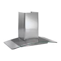
| Product Type | Range Hood |
| Brand | Frigidaire |
| Model | PLHV42P8CC |
| Width | 42 inches (106.7 cm) |
| Depth | 27 inches (68.6 cm) |
| Height (adjustable) | From 33 13/16 to 49 1/16 inches (85.9 to 124.6 cm) |
| Weight | 86 lbs (39 kg) |
| Power Supply | 120 V AC, 60 Hz, 15 or 20 A |
| Duct Diameter | 8 inches |
| Filter Type | Anodized aluminum anti-grease metal filters, washable |
| Lighting | 12 V halogen lamp, 20 W max, G-4 base |
| Suction Speeds | 3 speeds + intensive mode (10 minutes) |
| Panel Functions | Power LED, filter saturation indicator, reset |
| Filter Maintenance | Clean at least once a month, hand or dishwasher safe |
| Surface Cleaning | Soapy water or mild detergent, avoid abrasives |
| Safety | Disconnect power before maintenance, mandatory grounding |
| Warranty | 1 year full (parts and labor), limited for Alaska |
Frequently Asked Questions - PLHV42P8CC FRIGIDAIRE
User questions about PLHV42P8CC FRIGIDAIRE
0 question about this device. Answer the ones you know or ask your own.
Ask a new question about this device
Download the instructions for your Fan in PDF format for free! Find your manual PLHV42P8CC - FRIGIDAIRE and take your electronic device back in hand. On this page are published all the documents necessary for the use of your device. PLHV42P8CC by FRIGIDAIRE.
USER MANUAL PLHV42P8CC FRIGIDAIRE
natural_image
Isometric line drawing of a mechanical component with a hollow rectangular top and flange base (no text or symbols)READ AND SAVE THESE INSTRUCTIONS LISEZ ET CONSERVEZ CES INSTRUCTIONS LEER Y GUARDAR ESTAS INSTRUCCIONES
UK F E
Contents 2
Product Registration.... 2
Important Safety Instructions 3
Installation.... 4-8
Use and Care 9
Hood Cleaning 10
Lights Replacement 10
Warranty 11
Product Registration
Register your Product
The self-addressed PRODUCT REGISTRATION CARD should be filled in completely, signed and returned to the Frigidaire Canada.

This Owner's Guide contains general operating instructions for your range hood and feature information for several models. Your range hood may not have all the described features.
Note: The instructions appearing in this Owner's Guide are not meant to cover every possible condition and situation that may occur. Common sense and caution must be practiced when installing, operating and maintaining any appliance.
Thank you for choosing this appliance. The information contained within this Owner's Guide will instruct you on how to properly operate and care for your range hood. Please read through the information contained in your literature pack to learn more about your new appliance.
Record Your Model and Serial Numbers
Record in the space provided below the model and serial numbers found on the serial plate located on the right hand side of the range hood.
Model Number: ____
Serial Number: ____
Date of Purchase: ____
Important Safety Instructions
READ AND SAVE THESE INSTRUCTIONS
Take care when using cleaning agents or detergents.
Suitable for use in household cooking area
CAUTION - To reduce risk of fire and to properly exhaust air, be sure to duct air outside – Do not vent exhaust air into spaces within walls or ceilings or into attics, crawl spaces, or garages.
CAUTION - For General Ventilating Use Only. Do Not Use To Exhaust Hazardous Or Explosive Materials And Vapors.
WARNING – TO REDUCE THE RISK OF FIRE, ELECTRIC SHOCK, OR INJURY TO PERSONS, OBSERVE THE FOLLOWING:
a. Use this unit only in the manner intended by the manufacturer. If you have questions, contact the manufacturer.
b. Before servicing or cleaning unit, switch power off at service panel and lock the service disconnecting means to prevent power from being switched on accidentally. When the service disconnecting means cannot be locked, securely fasten a prominent warning device, such as a tag, to the service panel.
WARNING – TO REDUCE THE RISK OF A RANGE TOP GREASE FIRE:
a. Never leave surface units unattended at high settings. Boilovers cause smoking and greasy spillovers that may ignite Heat oils slowly on low or medium settings.
b. Always turn hood ON when cooking at high heat or when flambeing food (i.e. Crepes Suzette, Cherries Jubilee, Peppercorn Beef Flambee').
c. Clean ventilating fans frequently. Grease should not be allowed to accumulate on fan or filter.
d. Use proper pan size. Always use cookware appropriate for the size of the surface element.
WARNING – TO REDUCE THE RISK OF INJURY TO PERSONS IN THE EVENT OF A RANGE TOP GREASE FIRE, OBSERVE THE FOLLOWING:
a. SMOTHER FLAMES with a close-fitting lid, cookie sheet, or metal tray, then turn off the burner. BE CAREFUL TO PREVENT BURNS. If the flames do not go out immediately, EVACUATE AND CALL THE FIRE DEPARTMENT.
b. NEVER PICK UP A FLAMING PAN – You may be burned.
c. DO NOT USE WATER, including wet dishcloths or towels – a violent steam explosion will result.
d. Use an extinguisher ONLY if:
- You know you have a Class ABC extinguisher, and you already know how to operate it.
- The fire is small and contained in the area where it started.
- The fire department is being called.
- You can fight the fire with your back to an exit.
WARNING – TO REDUCE THE RISK OF FIRE, ELECTRIC SHOCK, OR INJURY TO PERSONS, OBSERVE THE FOLLOWING:
a) Installation work and electrical wiring must be done by qualified person(s) in accordance with all applicable codes and standards, including fire-rated construction.
b) Sufficient air is needed for proper combustion and exhausting of gases through the flue (chimney) of fuel burning equipment to prevent back drafting. Follow the heating equipment manufacturer's guideline and safety standards such as those published by the National Fire Protection Association (NFPA), and the American Society for Heating, Refrigeration and Air Conditioning Engineers (ASHRAE), and the local code authorities.
c) When cutting or drilling into wall or ceiling, do not damage electrical wiring and other hidden utilities.
d) Ducted fans must always be vented to the outdoors.
WARNING - TO REDUCE THE RISK OF FIRE, USE ONLY METAL DUCTWORK.
WARNING - TO REDUCE THE RISK OF FIRE OR ELECTRIC SHOCK, DO NOT USE THIS FAN WITH ANY SOLID-STATE SPEED CONTROL DEVICE.


WARNING
Electrical Shock Hazard - Can result in serious injury or death.
Disconnect appliance from electric power before servicing.
If equipped, the fluorescent light bulb contains small amounts of mercury which must be recycled or disposed of according to Local, State, and Federal Codes.
Installation
IMPORTANT: Save these Instructions for the Local Electrical Inspector's use.
INSTALLER: Please leave these Instructions with this unit for the owner.
OWNER: Please retain these instructions for future reference.
Safety Warning: Turn off power circuit at the service entrance and lock out panel, before wiring this appliance.
Requirement: 120 V AC, 60 Hz. 15 or 20 A
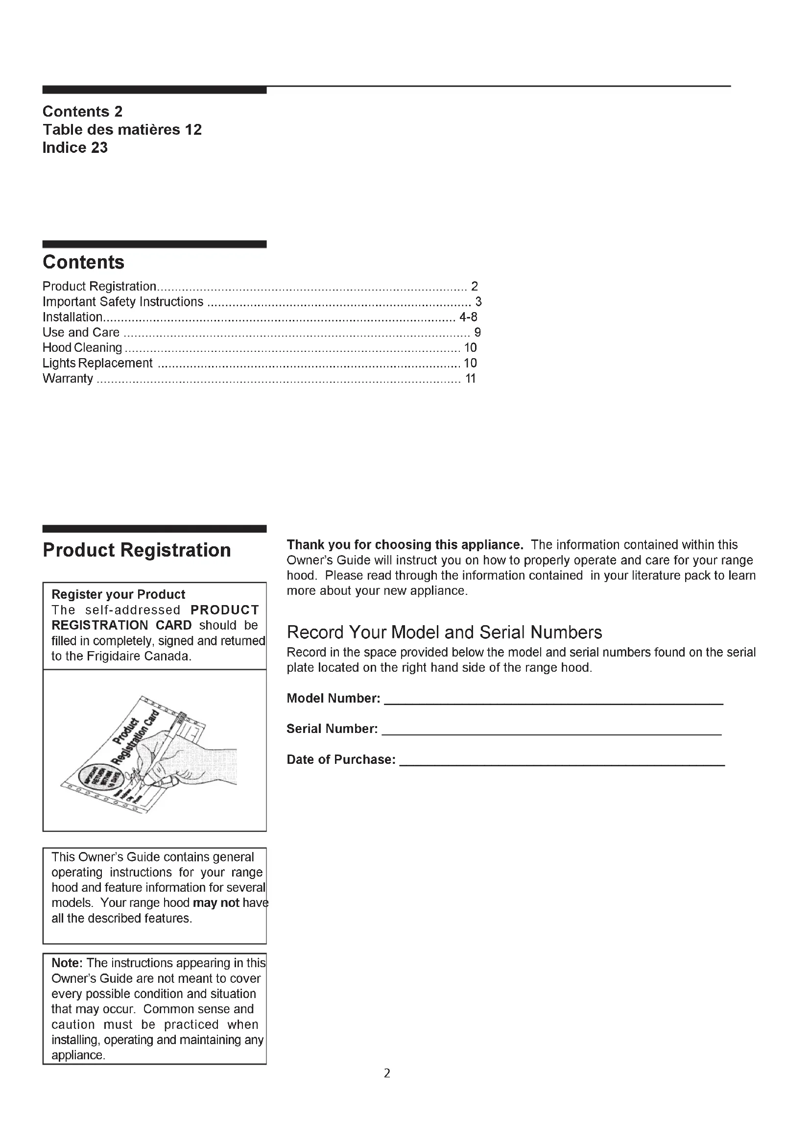
Dimensions - Table 1
Figure 1*
Weight: 86 pounds
Diameter of Transition 8"
Diameter of exhaust Duct required 8"
Note: All dimensions are shown in inches.
* Dimensions are given from base of hood to ceiling, and include clearance required for installation.
Considerations before installing Hood
- For the most efficient air flow exhaust, use a straight run or as few elbows as possible.
CAUTION: Vent unit to outside of building, only.
-
If allowed in your area, use metallic flex ducting only to connect rigid duct directly to transitions.
-
COLD WEATHER installations should have an additional backdraft damper installed to minimize backward cold air flow and a nonmetallic thermal break to minimize conduction of outside temperatures as part of the ductwork. The damper should be on the cold air side of the thermal break. The break should be as close as possible to where the ducting enters the heated portion of the house.
-
Hood installation height above cooktop is specified in Figure 2. Be sure that your hood model fits your installation.
Installation
Tools required for installation Screw driver (pozidrive n°2, torx 10 and 20) Allen spanner 4mm Shifting spanner 10mm pipe wrench 38 Electric drill with twist bit ∅ 10 mm
K = Kitchen Height
C = Counter Height (36" standard)
P = Height of Hood Bottom above counter not less than 30"
A = Canopy Height
H = Hood height your installation
H = K - C - P
S = Chimney Structure Height, your installation.
S = H - A
Figure 2
natural_image
Technical line drawing of a mechanical device with labeled components and no readable text or symbols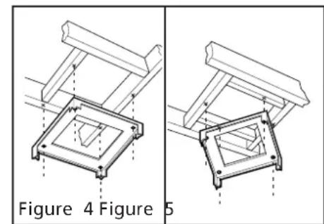
natural_image
Technical line drawing of a mechanical bracket assembly, showing two views labeled Figure 4 and Figure 5 (no text or symbols on the diagram itself)Pre-Installations Calculations (see Figure 2)
- a) Select a hood preference height P (see Figure 2) that is comfortable for the user not less than 30".
b) Calculate Hood height your installation H (see Figure 2). H = K-C-P.
c) Confirm that H is within the range of min to max H found for your hood. If not adjust your installation.
d) Calculate Chimney structure height S (use formulas in Figure 2, and check dimensions of your hood). Save this calculation for use later in the installation.
Preparation of Mounting Surface - Installing supports above ceiling drywall.
Note: Take into consideration the hood depth; your hood could be much deeper than the cooktop.
- Mark center lines of cooktop or range on ceiling above. Use centerlines marked on ceiling to position the mounting template. Note location of hood front, side, and mounting holes indicated on template.
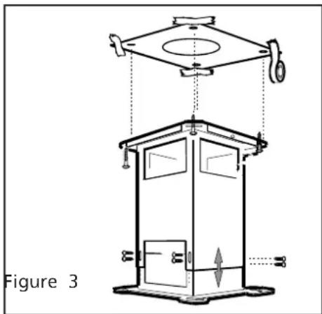
- Remove and save template. Cut and remove ceiling drywall. Install suitable length 2" x 4" lumber between joists to provide chimney mounting points as shown in Fig. 4 and 5. Use template for dimensions and required clearance. Make sure to affix the added lumber firmly and level. Consult a professional if yo have difficulties or your installation is unique. Consult template and Figures 3. 4. 5.
Note the weight of the appliance. (see Table1).
- Install an 8" exhaust duct. Female end shall be 4-1/2" below finished ceiling and securely fastened to joists. Do not use duct smaller than the transition.
- Install 1/2" electrical conduit in location marked on template and extend length S from ceiling.
- Install drywall around duct and conduit; then refinish ceiling.
Installation
natural_image
Line drawing of a hand holding a pen over a folded paper or cloth (no text or symbols)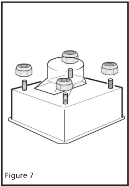
natural_image
Technical line drawing of a mechanical assembly with four bolts and a central housing (no text or symbols)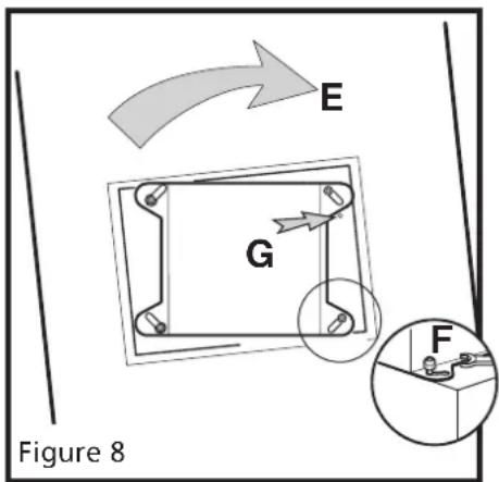
Appliance Installation
(Note: two people may be required for proper installation).
-
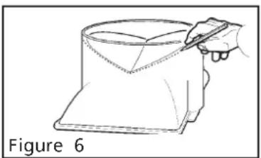
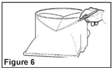
Install transition to top of hood (if removed for shipping). Snap damper into transition, foam tape up, with firm pressure at either end. Mark onto exterior of transition the 'V' location of the damper within. See Figure 6. Note: Duct screws can ONLY go below this line.
-
Adjust chimney mounting structure to S dimension as determined in Step 1, page 5. Use 2 screws per attachment leg. Do not fasten to ceiling now.
-
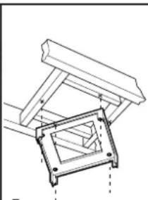
Set chimney mounting structure on top of hood canopy. Attach nuts loosely. See Figure 7 and 8.
-
Fit duct piece on transition so that top end is 5-1/2" below top of chimney structure, male end up.
-
Remove chimney structure from hood canopy.
-
Install Ducting. Fasten duct to transition with screws and tape per code. Loosely fasten starter collar (included) flush to top of duct. Note: screws must not hamper the damper (see 8. above for screw location). Loosely fasten starter collar (included) flush to bottom of duct.
-
To install Chimney Structure to ceiling, use a 10mm or adjustable wrench or flat head screwdriver. Drill pilot holes into ceiling. Attach mounting structure to joists with the 4 lag screws provided. (Keep 1/2" conduit inside structure.) See Figure 3.
-
To fasten the canopy use a 10mm or adjustable wrench. Affix nuts to top of canopy.
Do not tighten. Raise canopy up to chimney structure and twist in place. See Figure 8. Tighten nuts securely.
- Ducting for all units: There should be no more than 1" gap between canopy ducting and house ducting. Adjust starting collar over both ducts. Tighten collar. Fasten duct with screws and tape per code. Make final angular adjustment to unit at ceiling if necessary, then securely tighten 4 ceiling lag screws if not already tightened.
Installation

natural_image
Technical diagram of a mechanical assembly with labeled parts, showing internal components and housing (no text or symbols)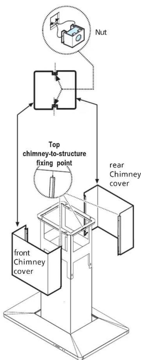
flowchart
graph TD
    A["front Chimney cover"] --> B["Top chimney-to-structure fixing point"]
    B --> C["rear Chimney cover"]
    D["Nut"] --> E["Top structure with nut connection"]
    style A fill:#f9f,stroke:#333
    style B fill:#ccf,stroke:#333
    style C fill:#cfc,stroke:#333
    style D fill:#fcc,stroke:#333
    style E fill:#cff,stroke:#333
Figure 11
Wiring to Power Supply
WARNING! ELECTRICAL GROUNDING INSTRUCTIONS
THIS APPLIANCE IS FITTED WITH AN ELECTRICAL JUNCTION BOX WITH 3 WIRES, ONE OF WHICH (GREEN/YELLOW) SERVES TO GROUND THE APPLIANCE. TO PROTECT YOU AGAINST ELECTRIC SHOCK, THE GREEN AND YELLOW WIRE MUST BE CONNECTED TO THE GROUNDING WIRE IN YOUR HOME ELECTRICAL SYSTEM, AND IT MUST UNDER NO CIRCUMSTANCES BE CUT OR REMOVED.
Warning: Turn off power circuit at the service panel before wiring this unit. 120 VAC, 15 or 20 Amp circuit required.
- Remove j-box cover as shown in Figure 10.
- Remove the knockout and install the strain relief (conduit) connector (1/2") in junction box.
- Run 3 wires; black, white and green (#16 AWG) in 1/2" conduit from service panel to junction box.
- Connect black wire from service panel to black or red in junction box, white to white and green to green-yellow. See Figure 10.
- Close junction box cover, check all light bulbs to make sure they are secure in their sockets, then turn power on in service panel and check lights and blower operation per Care & Use section of this manual and install filters.
Final assembly
For final Chimney Cover installation, DO NOT USE ELECTRIC SCREW DRIVER.
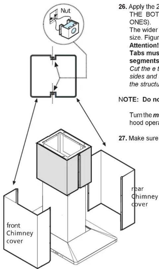
- Fit the nuts with fixing hooks supplied inside the top and bottom sections of the chimney covers at all the rectangular slots. Figure 11-12.
- Join the two top sections of the chimeny covers to cover the chimney structure. Screw the two sections together with 4 screws (2 each side- see the plan diagram for joining the two sections). Figure 11.
- Fix the covers to the structure, near the ceiling, with two screws (one each side) Figure 11.
Installation
flowchart
graph TD
    A["Front Chimney cover"] --> B["Chiptop"]
    B --> C["Nut"]
    C --> D["Chiptop"]
    D --> E["Chiptop"]
    E --> F["Chiptop"]
    F --> G["Chiptop"]
    G --> H["Chiptop"]
    H --> I["Chiptop"]
    I --> J["Chiptop"]
    J --> K["Chiptop"]
    K --> L["Chiptop"]
    L --> M["Chiptop"]
    M --> N["Chiptop"]
    N --> O["Chiptop"]
    O --> P["Chiptop"]
    P --> Q["Chiptop"]
    Q --> R["Chiptop"]
    R --> S["Chiptop"]
    S --> T["Chiptop"]
    T --> U["Chiptop"]
    U --> V["Chiptop"]
    V --> W["Chiptop"]
    W --> X["Chiptop"]
    X --> Y["Chiptop"]
    Y --> Z["Chiptop"]
    Z --> AA["Chiptop"]
    AA --> AB["Chiptop"]
    AB --> AC["Chiptop"]
    AC --> AD["Chiptop"]
    AD --> AE["Chiptop"]
    AE --> AF["Chiptop"]
    AF --> AG["Chiptop"]
    AG --> AH["Chiptop"]
    AH --> AI["Chiptop"]
    AI --> AJ["Chiptop"]
    AJ --> AK["Chiptop"]
    AK --> AL["Chiptop"]
Figure 12
-
Join the two bottom sections of the chimney covers to cover the chimney structure using 6 screws (3 each side, see the plan diagram for joining the two sections). Figure 12.
-
Slide down the bottom section of the covers in its seat so that it completely covers the motor compartment and electrical connection box. Figure 12.
-
Apply the 2 tabs (supplied) to cover the fixing points of the bottom flue (CAUTION! THE BOTTOM FLUE TABS ARE THE NARROWER AND SHALLOWER ONES).
The wider and deeper tabs are those used for the top flue, and must be cut to size. Figure 13.
Attention!
Tabs must be fixed using the double sided adhesive tape supplied (two segments each tab should be used!):
Cut the e tape into 8 segments, then remove the protection covering from both sides and apply the segments close to the screws that fix the chimney flues to the structure.
NOTE: Do not overtighten and deform metal.
Turn the main power on again at the central electrical panel and check for correct hood operation.
- Make sure to leave this manual for the home owner.
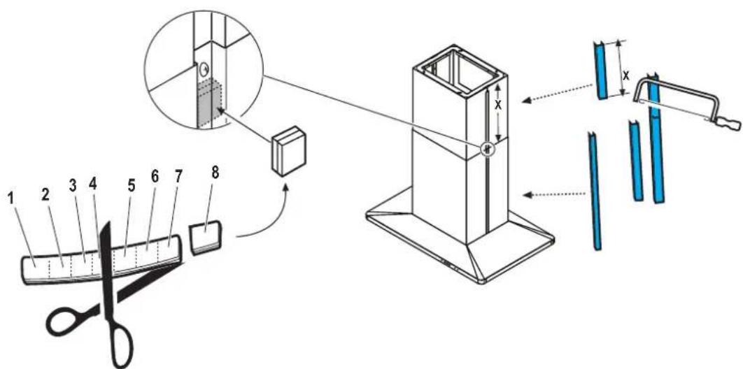
Figure 13
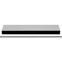
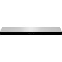
Use and Care Control Pad Functions
READ THE INSTRUCTIONS CAREFULLY BEFORE USING THE HOOD. For satisfactory use of your hood, become familiar with the various functions of the hood as described below
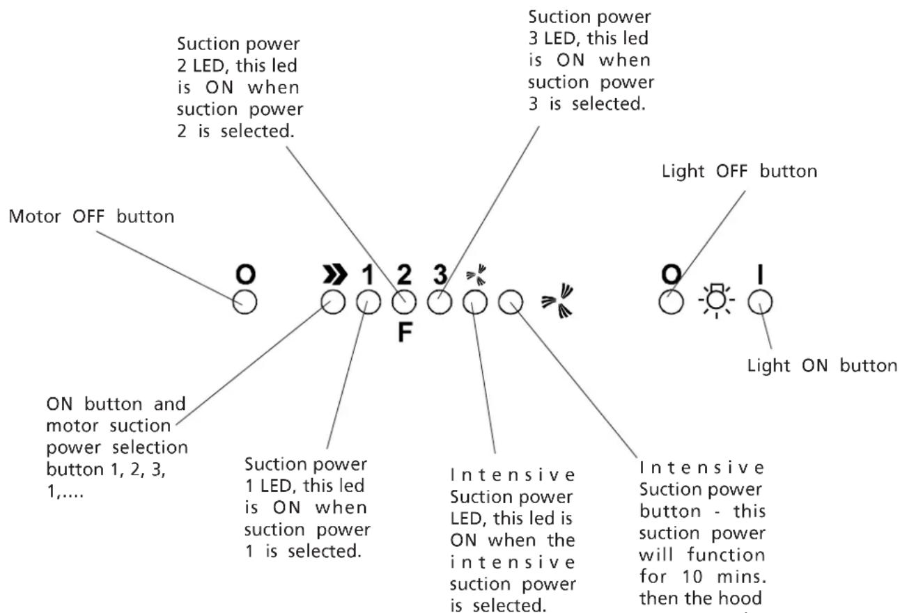
Figure 14
Grease Filter Saturation LED
The Suction power 2 LED in Figure 12 is marked with an F. This LED will flash to remind you when the grease filter needs to be cleaned after 40 hours use. Follow the instructions for cleaning filters in this booklet. Once the grease filters have been cleaned, reset the reminder by pressing Motor OFF button for about 3 seconds until you hear the signal (beep).
Operating Instructions
The blower should be turned on for about 5 minutes before cooking in order to establish air currents upward through the hood. Use the low speeds for normal use and the higher speeds for strong odors or fumes. Minimize cross drafts which will reduce the effectiveness of the hood.
Hood Cleaning
natural_image
Technical diagram showing a mechanical assembly with a magnified inset of a component detail (no text or symbols)Figure 15
Be sure lights are cool before cleaning the hood.
To Clean Filters
• The metal grease filters will last forever. They are made of anodized aluminum
- It is recommended that the filters be washed at least once a month; they can be washed by hand or in the dishwasher.
- Drain water through edge holes and let each filter dry thoroughly before replacing it.
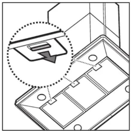
To Remove The Metal Grease Filters
- Disconnect the hood from electricity.
- Push clips towards the rear and pull the filters downward.
- Disengage each filter from a side and remove it
To Replace The Metal Grease Filters
- Reverse procedure.
To Clean Hood Surface
- For general care, wipe the outside of the stainless steel, white, black or glass hood with sudsy water or household cleaners such as Fantastic® or Formula 409®, rinse well and dry with clean soft cloth to avoid water marks.
- Wipe and dry brushed stainless steel in the same direction as the grain.
- Do not use abrasive products.
- To remove finger prints and give added shine use spray cleaners such as Stainless Steel Magic® and Shimmel®.
Lights replacement
Turn off electric power to hood before removing light cover.
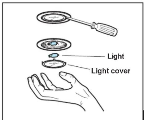
Figure 16
NOTE: Turn blower and lights off. Make sure the lights are cool. If new lights do not operate be sure lights are inserted correctly before calling service.
- Remove the light cover using a little flat screwdriver or similar tool as a lever.
- Remove the damaged light and replace with a new 12 Volt, 20 Watt (maximum) halogen light made for a G-4 base. Follow package directions and do not touch new light with bare hands.
- Reinstall the light cover (snap into position).
Contents 2
Figure 2
natural_image
Technical line drawing of a mechanical device with top and side views, labeled Figure 3 (no text or symbols on the diagram itself)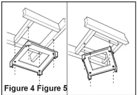
natural_image
Technical diagram showing two mechanical assembly views labeled Figure 4 and Figure 5, with no visible text or symbols on the components themselves.Installation
natural_image
Line drawing of a hand holding a pen over a cylindrical object, labeled 'Figure 6' (no text or symbols on the diagram itself)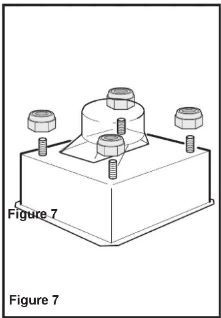
natural_image
Technical line drawing of a mechanical component with four bolts and a central housing, labeled Figure 7 (no text or symbols on the diagram itself)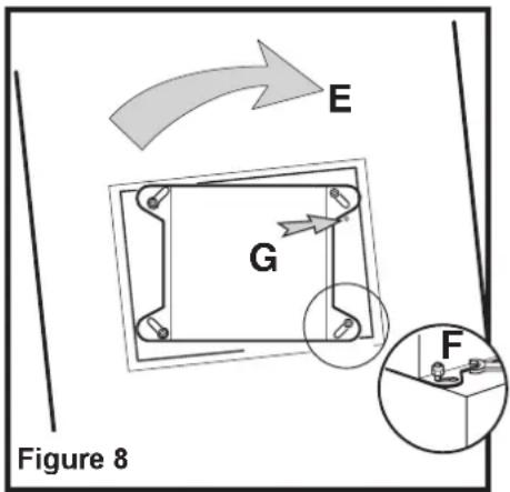
natural_image
Technical line drawing of a mechanical assembly with components and parts, labeled Figure 10 (no text or symbols on the diagram itself)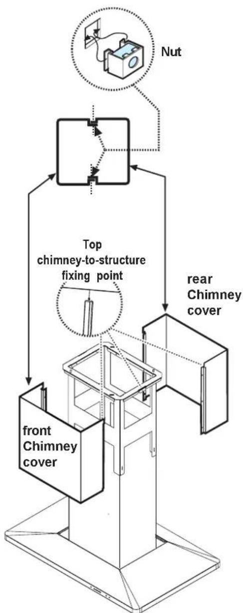
flowchart
graph TD
    A["front Chimney cover"] --> B["Top chimney-to-structure fixing point"]
    B --> C["rear Chimney cover"]
    D["Nut"] --> E["Top structure with dot connection"]
    style A fill:#f9f,stroke:#333
    style B fill:#ccf,stroke:#333
    style C fill:#cfc,stroke:#333
    style D fill:#fcc,stroke:#333
    style E fill:#cff,stroke:#333
Figure 11
Figure 13
Emploi et Entretien
natural_image
Technical diagram showing a mechanical assembly with an inset close-up of a component (no text or symbols present)Figure 15
Electrolux Home Products North America
P.O. Box 212378
Augusta, GA 30917
Canada
Electrolux Home Products North America
6150 McLaughlin Road
Mississauga, Ontario, Canada
L5R 4C2
Contents 2 Table des matières 12 Indice 23
Indice
Registro del aparato ....23
natural_image
Technical line drawing of a mechanical device with labeled components and no readable text or symbols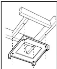
natural_image
Technical line drawing of a mechanical assembly with no visible text or symbolsFigura 4 Figura
natural_image
Technical line drawing of a mechanical assembly with no visible text or symbolsnatural_image
Line drawing of a hand holding a pen over a cylindrical object, labeled 'Figure 6' (no text or symbols on the diagram itself)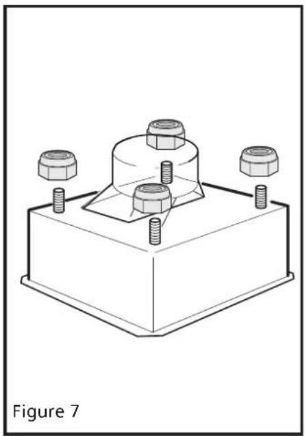
natural_image
Technical line drawing of a mechanical assembly with four bolts and a central housing (no text or symbols)
natural_image
Technical line drawing of a mechanical assembly with screws and a housing, labeled 'Figura 10' (no text or symbols on the diagram itself)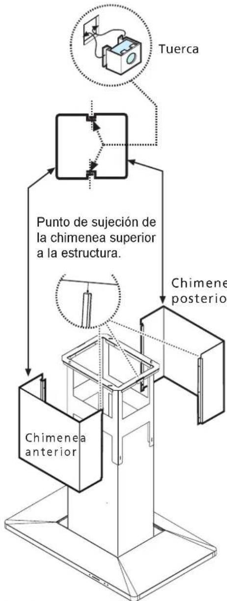
flowchart
graph TD
    A["Chimenea anterior"] --> B["Punto de sujeción de la chimenea superior a la estructura."]
    B --> C["Tuerca"]
    C --> D["Chimene posterior"]
Figura 11
Conexión eléctrica
Figura 13
natural_image
Technical line drawing of a mechanical assembly with a magnified inset showing a component detail (no text or symbols)Figure 15
Turn off electric power to hood before removing light cover.
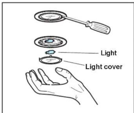
Figure 16
- Contents 2
- Product Registration
- Register your Product
- Record Your Model and Serial Numbers
- Important Safety Instructions
- READ AND SAVE THESE INSTRUCTIONS
- WARNING
- Installation
- Dimensions - Table 1
- Considerations before installing Hood
- Pre-Installations Calculations (see Figure 2)
- Preparation of Mounting Surface - Installing supports above ceiling drywall.
- Appliance Installation
- Wiring to Power Supply
- WARNING! ELECTRICAL GROUNDING INSTRUCTIONS
- Final assembly
- Attention!
- Use and Care Control Pad Functions
- Grease Filter Saturation LED
- Operating Instructions
- Hood Cleaning
- To Clean Filters
- To Remove The Metal Grease Filters
- To Replace The Metal Grease Filters
- To Clean Hood Surface
- Lights replacement
- Emploi et Entretien
- Canada
- Contents 2 Table des matières 12 Indice 23
- Indice
- Conexión eléctrica
Brand : FRIGIDAIRE
Model : PLHV42P8CC
Category : Fan