
PL36WC40EC - Fan FRIGIDAIRE - Free user manual and instructions
Find the device manual for free PL36WC40EC FRIGIDAIRE in PDF.
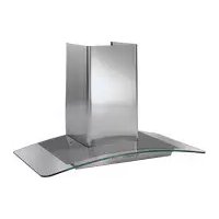
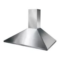
| Product Type | Range Hood |
| Brand | Frigidaire |
| Model | PL36WC40EC |
| Width | 36 inches (91.4 cm) |
| Recommended Mounting Height | 24 to 30 inches (61 to 76 cm) above cooking surface |
| Electrical Supply | 125 V, 15 A, 3-prong grounded outlet |
| Number of Speeds | 4 speeds + timer |
| Lighting | 2 halogen bulbs (JC, 12 V, 20 W max, G-4 base) |
| Filters | Grease filter (dishwasher safe) and charcoal filter (replace every 6 months) |
| Venting | 6-inch (15 cm) round metal duct to outside |
| Special Features | 10 min timer on speed 2, filter cleaning reminder with blinking LED |
| Material | Stainless steel |
| Maintenance | Clean with warm water and mild soap; avoid abrasive products |
| Safety | Motor protection thermostat, automatic shut-off in case of overheating |
| Warranty | 1 year parts and labor |
| Included Accessories | Mounting bracket, vent collar, support bracket, screws, wall anchors |
| Approximate Weight | 30 to 40 kg |
Frequently Asked Questions - PL36WC40EC FRIGIDAIRE
User questions about PL36WC40EC FRIGIDAIRE
0 question about this device. Answer the ones you know or ask your own.
Ask a new question about this device
Download the instructions for your Fan in PDF format for free! Find your manual PL36WC40EC - FRIGIDAIRE and take your electronic device back in hand. On this page are published all the documents necessary for the use of your device. PL36WC40EC by FRIGIDAIRE.
USER MANUAL PL36WC40EC FRIGIDAIRE
natural_image
Simple line drawing of a pedestal with a rectangular base and curved base, no text or symbols present.Model PL36WC40EC
ENGLISH....2
FRANÇAIS....10
READ AND SAVE THESE INSTRUCTIONS
- Use this unit only in the manner intended by the manufacturer. If you have questions, contact the manufacturer at the address or telephone number listed in the warranty.
- Before servicing or cleaning unit, switch power off at service panel and lock service panel to prevent power from being switched on accidentally. When the service disconnecting means cannot be locked, securely fasten a prominent warning device, such as a tag, to the service panel.
- Installation work and electrical wiring must be done by a qualified person(s) in accordance with all applicable codes and standards, including fire-rated construction codes and standards.
- Sufficient air is needed for proper combustion and exhausting of gases through the flue (chimney) of fuel burning equipment to prevent backdrafting. Follow the heating equipment manufacturer's guidelines and safety standards such as those published by the National Fire Protection Association (NFPA), and the American Society for Heating, Refrigeration and Air Conditioning Engineers (ASHRAE), and the local code authorities.
- When cutting or drilling into wall or ceiling, do not damage electrical wiring and other hidden utilities.
- Ducted fans must always be vented to the outdoors.
- Do not use this unit with any separate solid-state speed control device.
- To reduce the risk of fire, use only metal ductwork.
- This unit must be grounded.
TO REDUCE THE RISK OF A RANGE TOP GREASE FIRE:
A. Never leave surface units unattended at high settings. Boilovers cause smoking and greasy spillovers that may ignite. Heat oils slowly on low or medium settings.
B. Always turn hood ON when cooking at high heat or when flambeing food (i.e. Crepes Suzette, Cherries Jubilee, Peppercorn Beef Flambe').
C. Clean ventilating fans frequently. Grease should not be allowed to accumulate on fan or filter.
D. Use proper pan size. Always use cookware appropriate for the size of the surface element.
WARNING
TO REDUCE THE RISK OF INJURY TO PERSONS IN THE EVENT OF A RANGE TOP GREASE FIRE, OBSERVE THE FOLLOWING:*
- SMOTHER FLAMES with a close-fitting lid, cookie sheet, or metal tray, then turn off the burner. BE CAREFUL TO PREVENT BURNS. If the flames do not go out immediately, EVACUATE AND CALL THE FIRE DEPARTMENT.
- NEVER PICK UP A FLAMING PAN - You may be burned.
- DO NOT USE WATER, including wet dishcloths or towels - violent steam explosion will result.
- Use an extinguisher ONLY if:
A. You know you have a Class ABC extinguisher and you already know how to operate it.
B. The fire is small and contained in the area where it started.
C. The fire department is being called.
D. You can fight the fire with your back to an exit.
* Based on "Kitchen Fire Safety Tips" published by NFPA.
CAUTION
- To reduce risk of fire and to properly exhaust air, be sure to duct air outside. Do not vent exhaust air into spaces within walls or ceilings or into attics, crawl spaces, or garages.
- Take care when using cleaning agents or detergents.
- Avoid using food products that produce flames under the Range Hood.
- For general ventilating use only. Do not use to exhaust hazardous or explosive materials and vapors.
- To avoid motor bearing damage and noisy and/or unbalanced impellers, keep drywall spray, construction dust, etc. off power unit.
- Your hood motor has a thermal overload which will automatically shut off the motor if it becomes overheated. The motor will restart when it cools down. If the motor continues to shut off and restart, have the hood serviced.
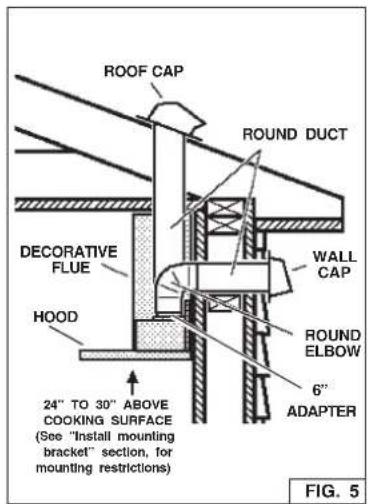
- For best capture of cooking impurities, the bottom of the hood should be a minimum of 24" and a maximum of 30" above the cooking surface. See "Install Mounting Bracket" section for mounting restrictions.
- Two installers are recommended because of the large size and weight of this hood.
- This product is equipped with a thermostat which may start blower automatically. To reduce the risk of injury and to prevent power from being switched on accidentally, switch power off at service panel and lock or tag service panel.
- Please read specification label on product for further information and requirements.
OPERATION
Controls
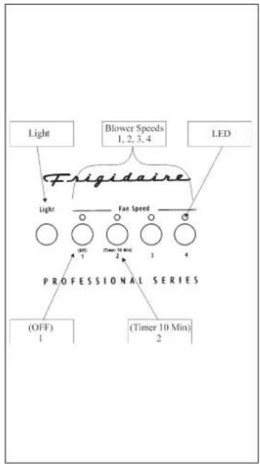
The hood is operated using the (5) push-buttons located at eye-level, on the front edge of the hood.
The light switch turns the halogen lights on and off. Push the light switch once to turn the lights ON - push a second time to turn the lights ON to a brighter level - push a third time to turn the lights OFF.
The blower on-off / speed 1 switch turns the blower on to its lowest running speed. To turn OFF the blower, push in and hold this blower switch for approximately 2 seconds.
The blower speed 2 switch turns the blower on to medium-low running speed. Pressing this switch a second time sets a timer which keeps the blower operating at this speed for 10 minutes. The LED will blink during this time and the blower will shut off automatically.
The blower speed 3 and blower speed 4 switches operate the same as blower speed 2 switch except: Blower speed 3 is medium-high and blower speed 4 is high.
After every 30 hours of operation, the LED above the "blower speed 1 switch" will be illuminated (RED) and blink for 30 seconds after turning off the blower. This is a reminder to clean the grease filters. Once the grease filters are cleaned and installed, press in and hold the "light switch" button for approximately 2 seconds during the blink of the LED.
flowchart
graph TD
    A["Light"] --> B["Prigidaire"]
    C["Blower Speeds 1, 2, 3, 4"] --> B
    D["LED"] --> B
    B --> E["Fan Speed"]
    E --> F["(OFF) 1"]
    E --> G["(Timer 10 Min) 2"]
    E --> H["(Timer 10 Min) 3"]
    E --> I["(Timer 10 Min) 4"]
    J["PROFESSIONAL SERIES"] --> K["(OFF) 1"]
    J --> L["(Timer 10 Min) 2"]
HALOGEN BULBS
This range hood requires two halogen bulbs (Type JC, 12Volt, 20Watt Max, G-4 Base).
⚠ WARNING: Always switch off the electrical supply before carrying out any operation on the appliance.
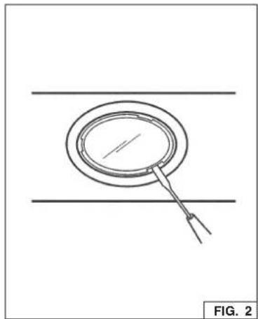
To change bulbs:
- Open the cover by prying from the proper slots.
- Remove the bulb by pulling sideways. (DO NOT ROTATE).

CAUTION: Bulb may be hot.
- Replace with Type JC, 12Volt, 20 Watt Max, G-4 Base halogen bulb. Do not touch replacement bulb with bare hands!

CAUTION: Use of bulbs greater than 20 watts will cause the fuse to en.
natural_image
Simple line drawing of a circular object with a connecting rod, placed on two parallel horizontal lines (no text or symbols)FUSE REPLACEMENT
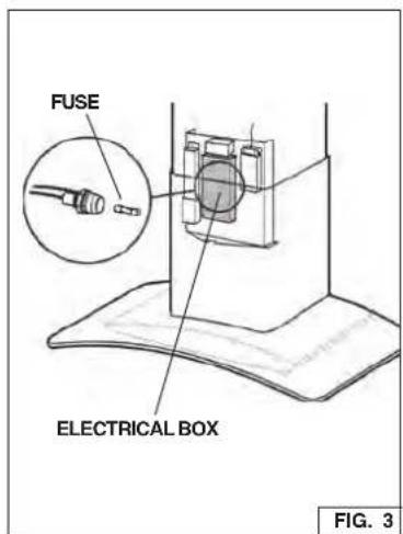
IF LIGHTS FAIL TO OPERATE, DISCONNECT POWER AT THE SERVICE ENTRANCE. CHECK THE FUSE AND REPLACE IF NECESSARY.
- Raise or remove the lower decorative flue. See Figure 3.
- Remove the cover from the electrical box.
- Unscrew the cap from the fuse holder and remove the fuse.
- Replace the fuse with the same size and amperage (5 x 20mm, 4 amp, 125 volt).

CAUTION: Use of a fuse greater than 4 amps may damage the transformer.
- Reinstall the fuse holder cap, electrical box cover and flue.
- Reconnect power at the service entrance.
Proper maintenance of the Range Hood will assure proper performance of the unit.
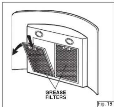
Grease Filters
The grease filters should be cleaned frequently. Use a warm detergent solution. Grease filters are dishwasher safe.
See "INSTALL FILTERS" section for removal and installation instructions.
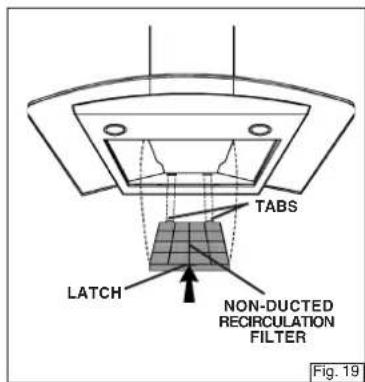
Non-Ducted Recirculation Filter
The non-ducted recirculation filter should be changed every 6 months.
See "INSTALL FILTERS" section for removal and installation instructions.
Hood Cleaning
Stainless steel is one of the easiest materials to keep clean. Occasional care will help preserve its fine appearance. Cleaning tips:
Hot water with soap or detergent is all that is usually needed.
Follow all cleaning by rinsing with clear water. Wipe dry with a clean, soft cloth to avoid water marks.
For discolorations or deposits that persist, use a non-scratching household cleanser or stainless steel polishing powder with a little water and a soft cloth.
For stubborn cases, use a plastic scouring pad or soft bristle brush together with cleanser and water. Rub lightly in direction of polishing lines or "grain" of the stainless finish. Avoid using too much pressure which may mar the surface.
DO NOT allow deposits to remain for long periods of time.
DO NOT use ordinary steel wool or steel brushes. Small bits of steel may adhere to the surface causing rust.
DO NOT allow salt solutions, disinfectants, bleaches, or cleaning compounds to remain in contact with stainless steel for extended periods. Many of these compounds contain chemicals which may be harmful. Rinse with water after exposure and wipe dry with a clean cloth.
Painted surfaces should be cleaned with warm water and mild detergent only.
PREPARE THE HOOD
Unpack hood and check contents.
You should receive:
1 - Hood
1 - Decorative Flue Assembly
1 - Parts Bag (B080810604) containing:
1 - Mounting Bracket
1 - Discharge Collar
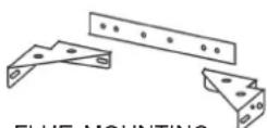
1 - Flue Mounting Bracket
6 - Mounting Screws (4,8 x 38mm Pan Head)
7 - Mounting Screws (3,9 x 9,5mm Pan Head)
2 - Mounting Screws (3.9 x 6mm Flat Head)
6 - Drywall Anchors
1 - Installation Instructions
1 - Warranty Card
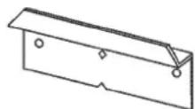
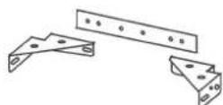
MOUNTING BRACKET
DISCHARGE
COLLAR
7 MOUNTING
SCREWS (3.9 x
9.5mm Pan Head)
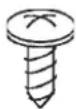
natural_image
Simple line drawing of a 3D rectangular box or container (no text or symbols)DECORATIVE FLUE

2 MOUNTING BRACKET
SCREWS
(3.9 x 6mm Flat Head)
FLUE MOUNTING
BRACKET
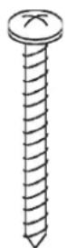
6 MOUNTING SCREWS (4.8 x 38mm Pan Head)
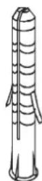
6 DRYWALL ANCHORS
FIG. 4
INSTALL THE DUCTWORK

CAUTION: To reduce the risk of fire, use only metal ductwork.
- Decide where the ductwork will run between the hood and the outside.
- A straight, short duct run will allow the hood to perform most efficiently.
- Long duct runs, elbows, and transitions will reduce the performance of the hood. Use as few of them as possible. Larger ducting may be required for best performance with longer duct runs.
- Install a roof or wall cap. Connect round metal ductwork to cap and work back towards hood location. Use duct tape to seal the joints between ductwork sections.
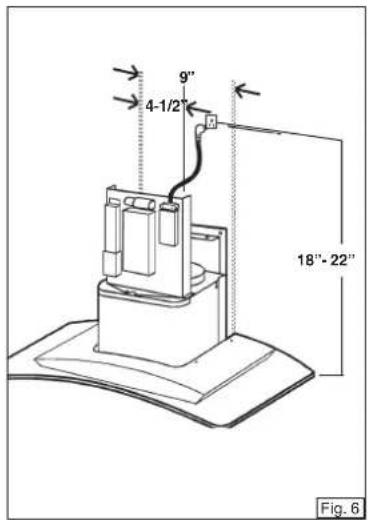
INSTALL ELECTRICAL

WARNING: Electrical wiring must be done by a qualified person(s) in accordance with all applicable codes and standards. This range hood must be properly grounded. Turn off electrical power at service entrance before wiring.
- Plan where the hood will be located above the cook top. Refer to the "INSTALL MOUNTING BRACKET" section for hood mounting height options.
- Install a standard 2" x 4" wall outlet box and 3-blade 125 volt, 15Amp grounded receptacle.
- Mount the receptacle 18" to 22" above the bottom of the hood.
- Locate the receptacle within boundary shown and off center of the ductwork (to allow for power cord plug and flue clearance).
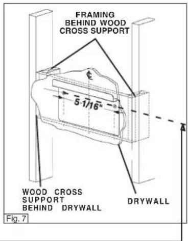
INSTALL MOUNTING BRACKET
(DUCTED AND NON-DUCTED HOODS)
- Construct wood wall framing that is flush with interior surface of wall studs.
Make sure:
a) the framing is centered over installation location.
b) the height of the framing will allow the mounting bracket to be secured to the framing within the dimensions shown.
- After wall surface is installed, secure the mounting bracket to framing with (2)
4.8x38mm mounting screws. See chart below for mounting bracket location.
| CEILING HEIGHT | DUCT METHOD | HOOD DISTANCE ABOVE 36" HIGH COOKTOP (SEE NOTE BELOW) | ||||||
| 24" 25" | 26" 27" | 28" 29" | 30" | |||||
| MOUNTING BRACKET LOCATION ABOVE 36" HIGH COOKTOP | ||||||||
| 8-FEET | DUCTED | 37" 38" | 39" 40" | 41" | ||||
| NON-DUCTED | 37" 38" | 39" 40" | ||||||
| 9-FEET | DUCTED ORNON-DUCTED | 37" | 38" 39" | 40" 41" | 42" | 43" | ||
| 10-FEET | DUCTED WITH5304447637 | 39" 40" | 41" 42" | 43" | ||||
NOTE : Minimum hood distance above cook top must not be less than 24". A maximum of 30" above cook top is highly recommended for best capture of cooking impurities. Distances over 30" are at the installer and user's discretion; and if ceiling height and flue lenght permit.
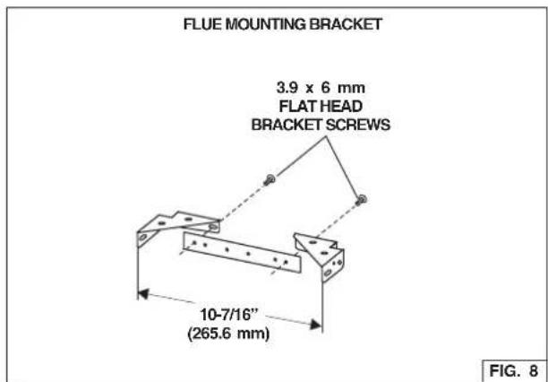
(DUCTED AND NON-DUCTED HOODS)
- Assemble the flue mounting bracket, adjusting outside width as shown. See Figure 8.
- Carefully center the mounting bracket directly over the range hood location.
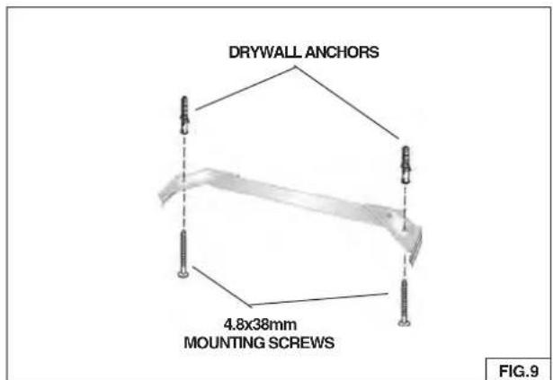
- Secure the bracket assembly to the ceiling using (2) 4.8x38mm mounting screws and drywall anchors (Fig. 9). Make sure the bracket is pushed into the corner, tight against the wall and centered over the hood.
PREPARE THE HOOD
Note: On stainless steel hoods, carefully remove the plastic protective film from all exterior surfaces of the hood and decorative flues, prior to final installation.
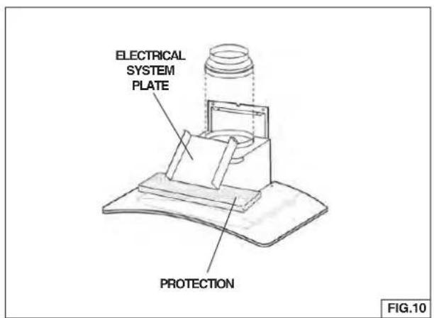
DUCTED HOODS ONLY
- Remove the tape on the electrical system plate; place the electrical system plate on the hood (use a protection). Fig. 10.
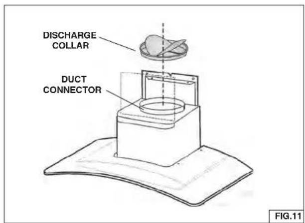
- Install the discharge collar into the duct connector of the range hood. Fig. 11.
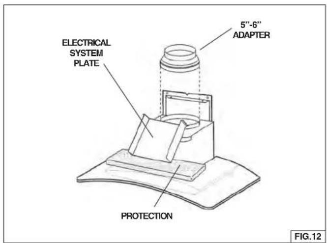
(NON - DUCTED HOODS ONLY)
Note: The following materials must be purchased separately for non-ducted recirculation installations.
Non - Ducted Recirculation Kit, Model 5304447635.
5" diameter duct.
- Remove the tape on the electrical system plate; place the electrical system plate on the hood (use a protection). Fig. 12
- Discard discharge collar/damper supplied with the hood. Install the 5" to 6" adapter supplied with the Non-Ducted Recirculation Kit.
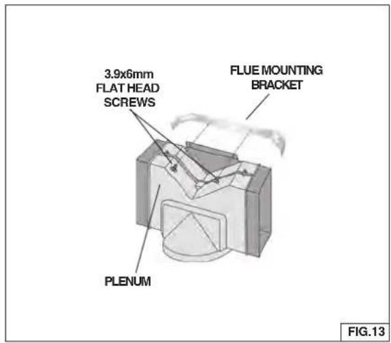
- Secure the plenum to the flue mounting bracket with (2) 3.9x6mm flat head screws (the screws are supplied with the Non-Ducted Recirculation Kit "5304447635"). Fig. 13.
INSTALL THE HOOD
Note: at least two people will be required to mount the hood.
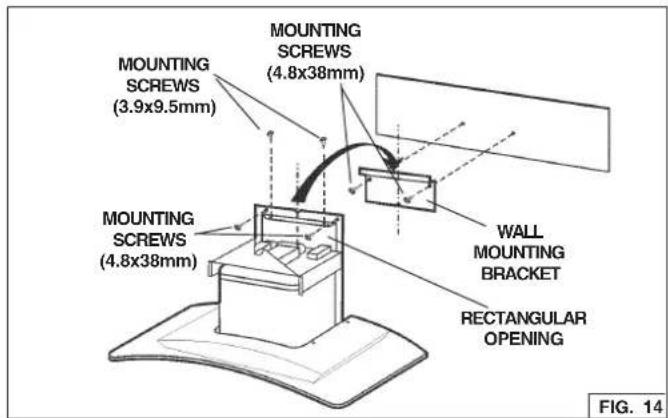
- Raise the hood into its mounting position.
- Align the rectangular opening on the back of the hood with the wall-mounting bracket. Gently lower the hood until it securely engages the bracket. Fig. 14.
- Level the hood with (2) 3.9x9.5mm mounting screws and secure with (2) 4.8x38mm mounting screws. Use drywall anchors provided if wall studs or framing are not available. Fig. 14.
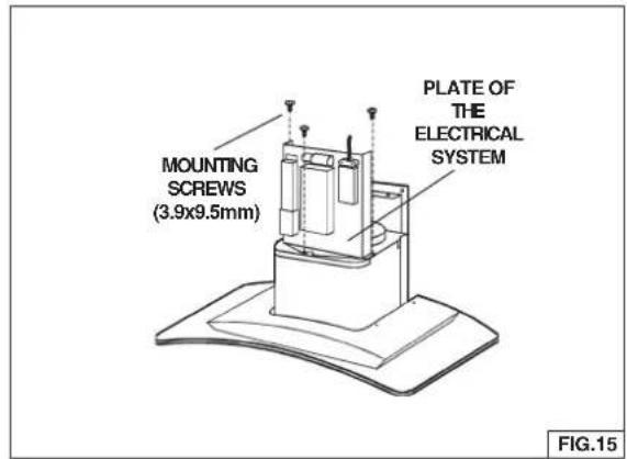
- Mount the electrical system plate attaching it with (3) 3.9x9.5mm mounting screws. Fig. 15.
- On ducted hoods, attach 6" round metal duct between the hood's blower collar and duct that leads to the outside location.
- On non-ducted hoods, attach 5" round metal expandable duct between the 5"-6" adapter on the hood the connector on the plenum.
- Tape all duct joints to make them secure and air tight.
- Plug the power cord into the electric wall receptacle. Tuck excess cord behind the flue.
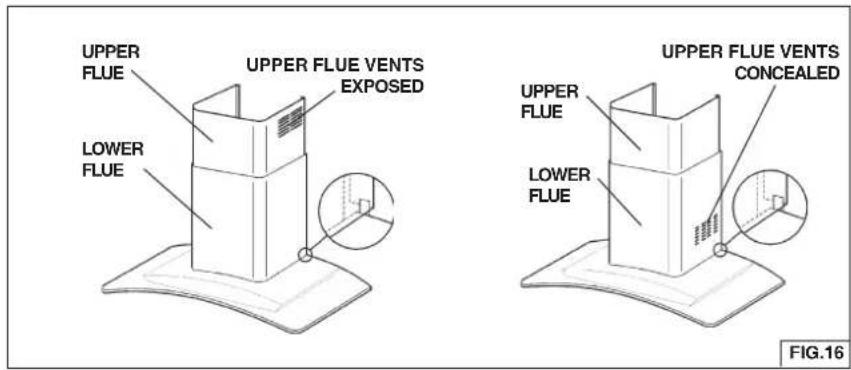
- Carefully place the decorative flue on the hood. Fig. 16.
- On ducted installation in rooms with 8-foot ceilings, the air vents are concealed. Install the flue with the air vents down.
- On non-ducted installations in rooms with 8-foot ceilings, the air vents are exposed. Install the flue with the air vents up.
- On ducted and non-ducted installations in rooms with 9-foot ceilings, the vents are exposed. Install the flue with air vents up.
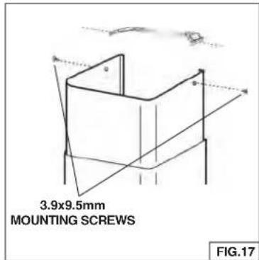
ROOMS WITH 10-FOOT CEILINGS
Rooms with 10-foot ceilings require flue extension model 5304447637, available from your local dealer.
-
Discard the upper flue supplied with the product. Replace it with the flue extension 5304447637.
-
Raise the upper flue until its holes align with holes in the flue mounting bracket (located on ceiling). Fig. 17.
- Secure the flue with (2) 3.9x9.5mm mounting screws. Fig. 17.
INSTALL FILTERS
(DUCTED AND NON-DUCTED HOODS)
- To remove the GREASE filter, push in on the metal latch tab and tilt filter downward to remove.
- To install the GREASE filter, align rear filter tabs with slots in the hood. Depress the metal latch tab, push filter into position and release. Make sure filter is securely engaged after installation.
NOTE: Prior to use, remove protective film from the filter frame.
(NON-DUCTED HOODS ONLY)
- To remove the CHARCOAL filter, push in on the front filter latch. Pull the filter down to disengage the rear filter tabs.
- To install the CHARCOAL filter, align the rear filter tabs with slots in the hood. Push the filter up into place until the front latch snaps securely into the slot. Make sure the filter is securely engaged after assembly.
- Install GREASE filter after charcoal filter is installed.
LIMITED WARRANTY
Your range hood is protected by this warranty
| WARRANTY PERIOD | THROUGH OUR AUTHORIZED SERVICERS WE WILL: | THE CONSUMER WILL BE RESPONSIBLE FOR: | |
| FULL ONE-YEAR WARRANTY | One year from original purchase date. | Pay all costs for repairing or replacing any parts of this appliance which prove to be defective in materials or workmanship. | Costs of service calls that are listed under NORMAL RESPONSIBILITIES OF THE CONSUMER.* |
| LIMITED WARRANTY (Applicable to the State of Alaska) | Time periods listed above. | All of the provisions of the full and limited warranties above and the exclusions listed below apply. | Costs of the technician's travel to the home and any costs for pick up and delivery of the appliance required because of service. |
In the U.S.A., your appliance is warranted by Electrolux Home Products, Inc. In Canada, your appliance is warranted by Electrolux Canada Corp. We authorize no person to change or to add to any of our obligations under this warranty. Our obligations for service and parts under this warranty must be performed by us or an authorized servicer.
\* NORMAL RESPONSIBILITIES OF THE CONSUMER
This warranty applies only to products in ordinary household use, and the consumer is responsible for the items listed below:
- Proper use of the appliance in accordance with instructions provided with the product.
- Proper installation by an authorized servicer in accordance with instructions provided with the appliance and in accordance with all local plumbing, electrical and/or gas codes.
- Proper connection to a grounded power supply of sufficient voltage, replacement of blown fuses, repair of loose connections or defects in house wiring.
- Expenses for making the appliance accessible for servicing, such as removal of trim, cupboards, shelves, etc., which are not a part of the appliance when it was shipped from the factory.
- Damages to finish after installation.
- Replacement of light bulbs and/or fluorescent tubes (on models with these features).
EXCLUSIONS
This warranty does not cover the following:
-
CONSEQUENTIAL OR INCIDENTAL DAMAGES SUCH AS PROPERTY DAMAGE AND INCIDENTAL EXPENSES RESULTING FROM ANY BREACH OF THIS WRITTEN OR ANY IMPLIED WARRANTY. Note: Some states do not allow the exclusion or limitation of incidental or consequential damages, so this limitation or exclusion may not apply to you.
-
Service calls which do not involve malfunction or defects in workmanship or material, or for appliances not in ordinary household use. The consumer shall pay for such service calls.
-
Damages caused by services performed by servicers other than Electrolux Home Products, Inc., Electrolux Canada Corp., or their authorized servicers; use of parts other than genuine Electrolux parts; obtained from persons other than such servicers; or external causes such as abuse, misuse, inadequate power supply or acts of God.
-
Products with original serial numbers that have been removed or altered and cannot be readily determined.
IF YOU NEED SERVICE
Keep your bill of sale, delivery slip, or some other appropriate payment record. The date on the bill establishes the warranty period should service be required. If service is performed, it is in your best interest to obtain and keep all receipts. This written warranty gives you specific legal rights. You may also have other rights that vary from state to state. Service under this warranty must be obtained by contacting Electrolux Home Products, Inc. or Electrolux Canada Corp.
This warranty only applies in the 50 states of the U.S.A., Puerto Rico, and Canada. Product features or specifications as described or illustrated are subject to change without notice. All warranties are made by Electrolux Home Products, Inc. or Electrolux Canada Corp. 2005 04
USA
1·800·944·9044
Electrolux Home Products, Inc.
P.O. Box 212378
Augusta, GA 30917
Canada
1•800•265•8352 (English or French)
Electrolux Canada Corp.
5855 Terry Fox Way
Mississauga, Ontario, Canada
L5V 3E4
LISEZ ET CONSERVEZ CES INSTRUCTIONS
SEULEMENT POUR UTILISATION DOMESTIQUE

AVERTISSEMENTS
POUR REDUIRE LES RISQUES D'INCENDIE, DE DECHARGES ELECTRIQUES OU DE DOMMAGES AUX PERSONNES, OBSERVEZ LES INSTRUCTIONS SUIVANTES:
natural_image
Simple line drawing of a magnifying glass over two parallel lines, no text or symbols present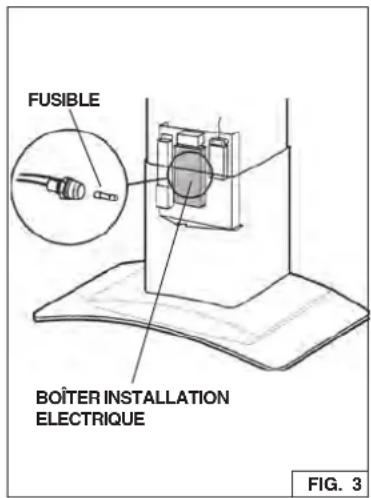
ENTRETIEN
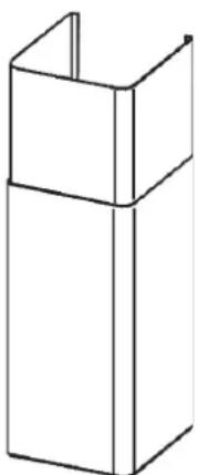
natural_image
Simple line drawing of a stacked rectangular box (no text or symbols)CARNEAU DECORATIVE

2 VIS D'ASSEMBLAGE (3.9 x 6mm Tête Plate)
ETRIER DE SUPPORT
6 VIS D'ASSEMBLAGE
(4.8 x 38mm Tête ronde)

6 CHEVILLES
FIG. 4
INSTALLATION DU SYSTEME D'EVACUATION

INSTALLATION SUPPORT DE FIXATION
(HOTTES CARÉNÉES OU NON CARÉNÉES)
(HOTTES CARÉNÉES OU NON CARÉNÉES)
FIG.9
PRÉPARATION DE LA HOTTE
(CONFIGURATIONS CARÉNÉES ET NON CARÉNÉES)
(CONFIGURATIONS NON CARÉNÉES)
Electrolux Home Products, Inc.
P.O. Box 212378
Augusta, GA 30917
Canada
1·800·265·8352 (English or French)
Electrolux Canada Corp.
5855 Terry Fox Way
Mississauga, Ontario, Canada
L5V 3E4
| KEY NO. | PART NO. | DESCRIPTION |
| 9 B08 | 087294 Grease Filter | |
| 14 B02 | 300233 Motor Capacitor | |
| 16 BE | 348100 Electrical System Plate | |
| 19 B03 | 295005 Terminal Box | |
| 26 B02 | 300891 Halogen Lamp Bulb | |
| 38 B03 | 292357 Control Board Box | |
| 38 BW | 0000027 Control Boards + Trimming | |
| 39 B03 | 294033 Control Board Cover | |
| 45 BW | 0000019 Blower | |
| 48 B02 | 310203 Motor | |
| 49 B03 | 295076 Blower Wheel | |
| 53 B03 | 202007 Rubber Washer | |
| 60 B02 | 300249 Feeder Cable | |
| 62 B08 | 091397 Blower Mounting Cover | |
| 76 B02 | 005036 Glass | |
| 86 B08 | 088378 Discharge Collar | |
| 92 BE | 348181 Switch Mounting Bracket | |
| 110 B03 | 202430 Flue Gasket | |
| 110 B02 | 000509 Glass Gasket | |
| 118 BE | 343563 Lower Flue | |
| 119 BE | 343560 Upper Flue | |
| 120 B08 | 091367 Flue Mounting Bracket | |
| 144 B03 | 292287 Wire Clamp | |
| 145 B03 | 2920170 Feeder cable connection Box | |
| 146 B03 | 2920180 Feeder Cable Connection Box Cover | |
| 147 BR | 2300132 Junction Clamp | |
| 151 B03 | 2920200 Electrical Box Wires Stop | |
| 165 B03 | 295008 Control Board Box | |
| 166 B08 | 086662 Control Board | |
| 208 B02 | 300783 Transformer | |
| 223 B03 | 292296 Switch Button | |
| 230 B03 | 292477 Switch Board Box Cover | |
| 234 B03 | 292476 Control Board Box | |
| 332 B03 | 295009 Cover | |
| 407 BE | 344985 Blower Support Bracket | |
| 472 BE | 343673 Bracket | |
| 474 B02 | 300798 Halogen Lamp Housing | |
| 477 B03 | 294776 Terminal Cover | |
| 998 B08 | 0810604 Hardware Package | |
| * B06 | 002013 Blower Assembly (Includes Key Nos. 45, 48, 49, 53) | |
| * B06 | 108543 Switch Assembly (Includes Key Nos. 234, 38, 223, 230) | |
| - B03 | 300488 Non-ducted recirculation filter | |
| - B08 | 999029 Non-ducted recirculation KIT | |
| - B02 | 300782 Fuse | |
| - B02 | 300674 Fuse holder |
* Not shown assembled.
99043735A
04307455/1
- READ AND SAVE THESE INSTRUCTIONS
- TO REDUCE THE RISK OF A RANGE TOP GREASE FIRE:
- WARNING
- CAUTION
- OPERATION
- Controls
- HALOGEN BULBS
- FUSE REPLACEMENT
- Grease Filters
- Non-Ducted Recirculation Filter
- Hood Cleaning
- PREPARE THE HOOD
- INSTALL THE DUCTWORK
- CAUTION: To reduce the risk of fire, use only metal ductwork.
- INSTALL ELECTRICAL
- INSTALL MOUNTING BRACKET
- (DUCTED AND NON-DUCTED HOODS)
- DUCTED HOODS ONLY
- (NON - DUCTED HOODS ONLY)
- INSTALL THE HOOD
- ROOMS WITH 10-FOOT CEILINGS
- INSTALL FILTERS
- (NON-DUCTED HOODS ONLY)
- LIMITED WARRANTY
- Your range hood is protected by this warranty
- \* NORMAL RESPONSIBILITIES OF THE CONSUMER
- EXCLUSIONS
- IF YOU NEED SERVICE
- USA
- Canada
- LISEZ ET CONSERVEZ CES INSTRUCTIONS
- SEULEMENT POUR UTILISATION DOMESTIQUE
- AVERTISSEMENTS
- POUR REDUIRE LES RISQUES D'INCENDIE, DE DECHARGES ELECTRIQUES OU DE DOMMAGES AUX PERSONNES, OBSERVEZ LES INSTRUCTIONS SUIVANTES:
- ENTRETIEN
- INSTALLATION DU SYSTEME D'EVACUATION
- INSTALLATION SUPPORT DE FIXATION
- (HOTTES CARÉNÉES OU NON CARÉNÉES)
- PRÉPARATION DE LA HOTTE
- (CONFIGURATIONS CARÉNÉES ET NON CARÉNÉES)
- (CONFIGURATIONS NON CARÉNÉES)
Brand : FRIGIDAIRE
Model : PL36WC40EC
Category : Fan