
M32000001 - Scale ADE - Free user manual and instructions
Find the device manual for free M32000001 ADE in PDF.

| Product type | Medical electronic personal scale |
| Brand | ADE |
| Model | M32000001 |
| Dimensions (with long column) | 450 x 355 x 960 mm |
| Dimensions (with short column) | 450 x 355 x 200 mm |
| Weight (with long column) | 8.4 kg |
| Weight (with short column) | 6.1 kg |
| Housing material | ABS |
| Mains power | Mains adapter 100-240 V AC, 50/60 Hz, output 6 V DC |
| Battery power | 4 AA alkaline batteries 1.5 V |
| Maximum capacity | 250 kg |
| Accuracy (single range) | ±100 g (0-50 kg), ±200 g (50.1-200 kg), ±300 g (200.1-250 kg) |
| Accuracy (dual range) | ±50 g (0-25 kg), ±100 g (25.1-50 kg), ±200 g (50.1-200 kg), ±300 g (200.1-250 kg) |
| Functions | Weighing, mother/baby function, Hold function, Tare function, BMI calculation, display rotation (Turning), optional Bluetooth |
| Display | Backlit LCD screen |
| Operating temperature | +10 °C to +40 °C |
| Operating humidity | 10% - 95% RH |
| Protection class | IP20 |
| Cleaning | Damp cloth or suitable disinfectant; do not use abrasive products. The PMMA screen is sensitive to alcohol. |
| Maintenance | Regular calibration, recommended revision every 3 to 5 years |
| Warranty | 2 years (parts and labor) |
| Included accessories | Mains adapter, 4 AA batteries, user manual, declaration of conformity |
| Optional accessories | Carrying case (ref. MZ10062) |
Frequently Asked Questions - M32000001 ADE
User questions about M32000001 ADE
0 question about this device. Answer the ones you know or ask your own.
Ask a new question about this device
Download the instructions for your Scale in PDF format for free! Find your manual M32000001 - ADE and take your electronic device back in hand. On this page are published all the documents necessary for the use of your device. M32000001 by ADE.
USER MANUAL M32000001 ADE
natural_image
Two digital balance meters displayed side by side, one tall and one square with a digital display (no visible text or symbols)EN Instruction Manual – Electronic personal scale 24
2.1 General safety instructions.... 25
2.2 Safety symbols.... 27
-
Scope of delivery 28
-
Overview.... 28
4.1 Key names and functions.... 29
4.2 Display symbols 29
- Getting started with the scale 30
-
How it works 31
-
Using the scale 31
7.1 Starting the scale 31
7.2 Switching off the scale 32
7.3 Correct weighing 32
7.4 Turning function 32
7.5 Mother/child function 32
7.6 Hold function 32
7.7 Tare function 32
7.8 BMI function 33
7.9 Beep 33
7.10 Bluetooth 33
- Care and maintenance 34
8.1 Cleaning 34
8.2 Disinfection.... 34
8.3 Sterilisation.... 34
8.4 Faults and error messages 34
8.5 Maintenance.... 35
8.6 Recalibration 35
8.7 Storage and Transport Conditions 35
8.8 Accessories 35
8.9 Disposal 36
8.10 Warranty 36
-
Technical Data.... 37
-
Symbol description.... 38
- Electromagnetic compatibility.... 39
- CE marking and declaration of conformity 42
- Contact information of the manufacturer 42
1. Intended use
Your ADE electronic personal scale is a prime quality product designed for weighing of people who can step on the scale by themselves. In addition, the person must be able to stand firm and unaided on the scale throughout the weighing process. The integrated mother/child function allows the weighing of toddlers held by the mother or any other person.
The scale may be used in all professional health care institutions, for medical, diagnostic and recovery purposes that require mandatory calibration.
The maximum capacity of the scale is 250 kg. To achieve precise results, please read the user guide carefully and follow the instructions contained therein. The scale may only be operated and maintained by trained personnel.
The device may only be used as intended. All applications of the device not mentioned in the chapter "Intended use" are considered as improper use. It is the user of the device, but not the manufacturer, who assumes liability for any resulting damage to property or personal injury resulting from misuse.
The use of accessories other than the original accessories supplied by the manufacturer may void this warranty.
Warning:

This device may not be modified without the manufacturer's permission.
Do not touch the mains adapter outlet connector/battery and the person on the scale at the same time during weighing.
Do not use the device in an oxygen-rich environment.
2. Safety information
2.1 General safety instructions
Be sure to read, understand and follow all instructions in this User Guide and others that come with the system and its components, as well as country-specific installation standards, applicable safety regulations and accident prevention regulations.
- Handle the scale with care and always keep in mind that it is a precision measuring instrument.
- Make sure, that patient is positioned in center of scale.
- Do not use the scale if one or more security marks are damaged.
- Do not use the scale if the calibration counter reading displayed when the scale is switched on does not match the number marked on the valid calibration counter mark.
- The scale may only be operated and maintained by trained and authorised skilled personnel.
- Before first use, make sure that the mains voltage and current type stated on the name plate match the mains voltage and current type at the place of use.
- Only authorised ADE power adapters may be used. Otherwise, there is a risk that other electrical devices will be affected.
- Only Bluetooth devices authorised by the manufacturer ADE may be connected. Otherwise, there is a risk that the specified performance level will be compromised.
- Anyone connecting additional equipment or power supply (other than specified in section 9) to the equipment is responsible that the system complies with the requirements of the standard IEC 60601-1.
- The plug/adapter plug insulates the device from the main supply. Do not position the device in a position where it is difficult to disconnect from the supply mains to safely terminate operation of me equipment.
-
Make sure to lay the power cord between the scale and mains connection so as to preclude a tripping hazard.
-
Make sure to lay the power cord between the scale and mains connection so as to preclude a strangulation hazard.
- Never move the scale back and forth at the place of use as this may cause damage to the load cells.
- Operate the device only within the permissible ambient conditions.
- After starting up the scale (connect it to the power supply and turn on the main switch), the scale must warm up for 15 minutes. Accuracy is only guaranteed after this time.
- Do not expose the scale to high temperatures, whether from neighbouring devices or direct sunlight. The liquid crystal display may suffer damage.
- Use the scale at constant ambient temperatures and avoid using in draughts, otherwise the measurement results could be falsified.
- After Storage under extreme conditions at least 60 min required until the scale has acclimated and is ready for intended use.
- If possible, place the scale away from other devices or sources that generate electromagnetic or other disturbances as these can falsify the measurement results.
- Use only approved accessories and peripherals. The use of unauthorised accessories or cables will invalidate the classification of the scale as a medical device.
- Before cleaning the device, disconnect the mains adapter from the mains.
- Do not immerse the device in water or other liquids.
- If the scale will not be used for a long time, it should be cleaned and stored in a protective film. The addition of a drying agent is desirable.
- Remove the batteries if you are not going to use the scale for a long time.
- If you have any problems with this device, such as setting up, maintaining or using, please contact authorised customer support. Do not open or repair the device by yourself.
- Please report authorised customer support if any unexpected operation or events occur.
DO NOT use the scale:
- If the mains adapter is damaged;
- If the mains adapter is not working;
- If the battery compartment has an unnatural bulge;
- After long storage in a humid environment.
In such cases, please contact authorised customer support.
Symbol Meaning Symbol Meaning

Keep away from babies and toddlers! Do not pull over your head! There is a choking hazard!
Pay attention to correct polarity. There is an explosion hazard!

Do not damage batteries/rechargeable batteries. There is an explosion hazard!
Batteries/rechargeable batteries are not a toy. There is a choking hazard!
Do not throw batteries/rechargeable batteries into fire. There is an explosion hazard!
Do not damage batteries/rechargeable batteries. There is an explosion hazard!
Keep the device out of the reach of children/pets to avoid inhalation or swallowing of small parts. If you are allergic to plastic/rubber, please don't use this device.
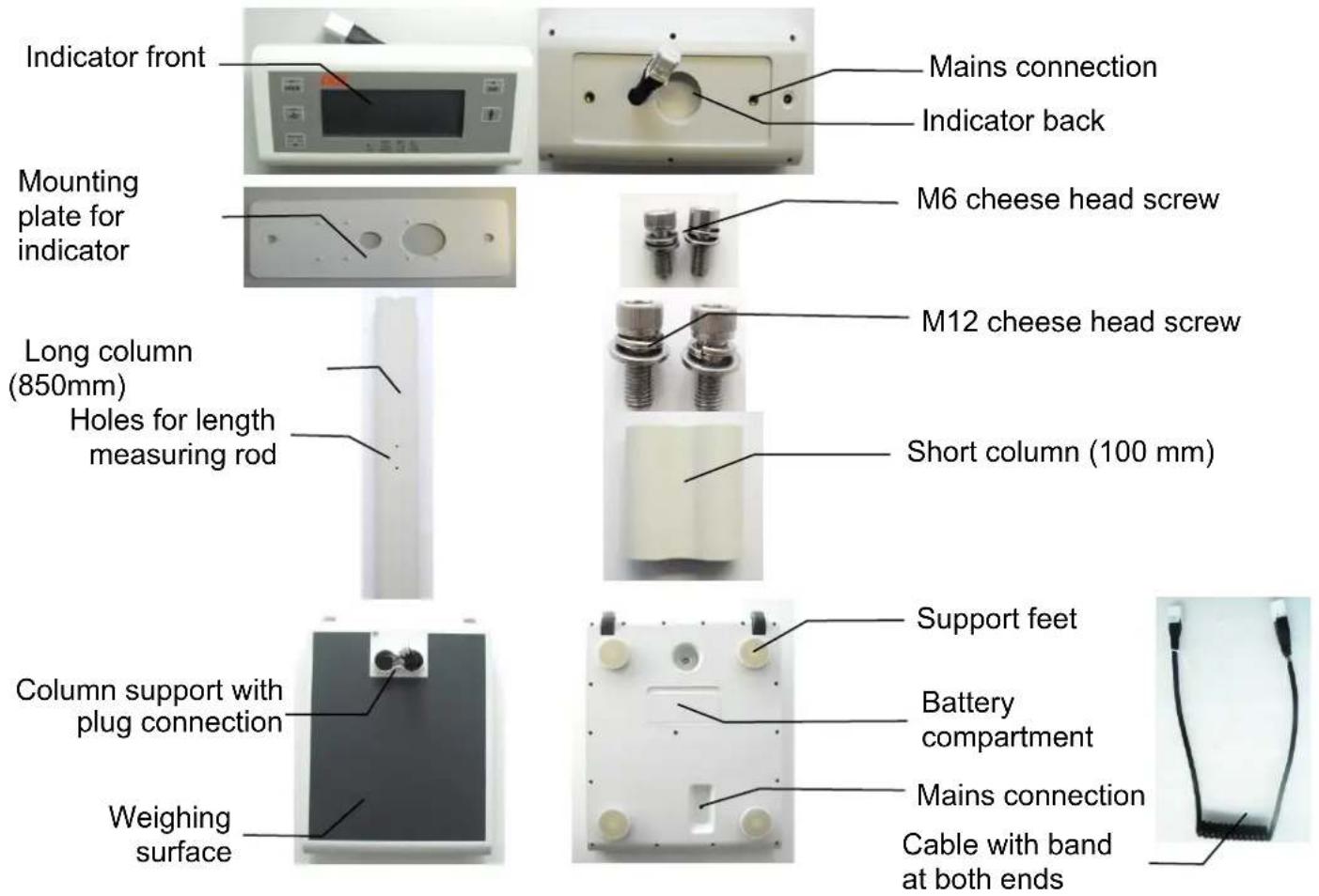
3. Scope of delivery
Check the scope of delivery for completeness immediately upon receipt of the scale:
- Indicator - Spiral cable (at 850mm column) - 4x1.5 V AA batteries
- Mounting plate - 2x M12 screw - AC Power adapter
- 2x M6 screw - Scale platform - User Guide
-
Column - 4 support feet - Declaration of Conformity
-
Overview


Illustration: dual-range scale
4.1 Key names and functions
| Symbol | Description | Function |
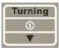 | ON/OFF | Multi-function key: ⏻: The second function of this key is switching on the scale. Turning: While in operation, this key is used to turn the displayed values. ▼: Use this key to decrease the body height of the BMI function. |
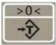 | TARE | Tare key: Enables the tare function. |
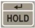 | HOLD | Multi-function key: ENTER: Use this key to confirm the body height of the BMI function. HOLD: Enables the automatic hold function. |
 | BMI | Multi-function key: BMI: Before stepping on the scale, press the key to enter the BMI calculation ▲: Use this key to increase the body height of the BMI function. |
 | M/C | Mother/child key: Enables the mother/child function. |
4.2 Display symbols
| Symbol Meaning | |
| [20770] | Mother/child function: The sign appears when the mother/child function is enabled. |
| "BMI" BMI function: The sign appears when the BMI function is enabled. | |
| "Hold" Hold function The sign appears when the hold function is enabled. | |
| "Net" | Tare function: The sign appears when the tare function is enabled. The display shows the net weight.Mother/child function: The sign appears when the child's net weight is displayed. |
| >0< The scale is in zero position. | |
| ~ | The weighing result is stable. |
| "kg" Calculated weight in kilograms (kg). | |
| "cm" Body height of the patient in cm, with BMI function | |
5. Getting started with the scale
- Carefully unpack the scale and accessories and remove all packaging materials.
- Remove both M12 cheese head screws from the column.
- The cable has a band at both ends.
- Insert the cable end and the smaller plug of the band in the opposite direction of the arrow through the column.
- Connect the small plug to the scale platform.
- Do not pull the scale platform by the plug. Insert it as far as possible in the inside of the scale platform.
- Place the column on the support of the scale platform.
- Place the scale on its side.
- Screw the scale platform and the column using the M12 cheese head screw provided for this purpose.
- Set up the scale.
- Mount the mounting plate to the end of the column marked by the arrow (indicator side). Make sure that the positioning aids point to the column.
- Screw the mounting plate and the column using the M12 cheese head screw provided for this purpose.
- Connect the free end of the cable to the indicator. Use the band to pull the cable end through the mounting plate, if necessary.
- Place the indicator on the mounting plate. Screw the mounting plate and the indicator using the two M6 cheese head screws provided for this purpose.
- Insert the 4 supplied 1.5V AA batteries in the battery compartment. When inserting the batteries, pay attention to the correct polarity (as shown in the battery compartment) and that the insulation of the batteries is undamaged.
- For mains operation, connect the supplied mains adapter to the mains connection.
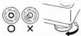
- Place the scale on a level, stable surface.
- Align the scale using the support feet. Make sure that the air bubble of the spirit level is centred in the black frame.
- Use the main switch to switch on the scale. After the warm-up time (15 minutes), the scale is ready for use.

Check the horizontal position of the scale after every change of location!
6. How it works
The mechanical forces acting on the scales are transformed into measurable and evaluable electrical signals by load cells. The weighing result is displayed continuously.
7. Using the scale
7.1 Starting the scale
7.1.1 Per key
To switch on the scale, briefly press the ON/OFF key.
After a brief functional test, the scale will show "0.00 kg" and the symbol >0<.
The scale is now ready for use.
The scale will start automatically with the last function used. When used for the first time, the scale will start automatically with the hold function.
7.1.2 Tap to start
Briefly load the weighing surface of the scale by briefly "tapping" it with your foot. If done correctly, a short functional test will follow, at the end of which the scale will show "0.00 kg" and the symbol >0<. The scale is ready for use.
7.2.1 Automatic switch off
The scale will switch off automatically after 90 seconds in battery mode and after 7 minutes in mains operation.
7.2.2 Per key
To switch off the scale, press and hold down the ON/OFF key for about 2 seconds.
The scale will automatically save the last setting used.
7.3 Correct weighing
Begin weighing only when "0.00 kg" and the symbol >0< appear on the display. Do not load the scale beforehand. Stand as firm as possible on the weighing surface. The weight can be read off directly after standstill.
7.4 Turning function
To turn the display indication, briefly press the ON/OFF key (<1 second).
7.5 Mother/child function
Switch on the scale with no load. Wait for "0.00 kg" and the symbol >0< to appear on the scale display.
Press the M/C key. The M/C symbol will appear on the display. Stand as firm as possible on the scale. The scale will save the weight reading and display "0.00 kg". In addition, the symbol Net will appear.
Unload the scale. “----” is shown on the display.
Now take a child by the hand and have them step on the weighing surface again.
The weight will be automatically stabilised and the child's weight will be displayed. When unloading the scale, the blinking weight reading with the symbol Hold will still be displayed.
7.6 Hold function
When the weighing surface is no longer loaded, the weight reading will still be displayed with the hold function (automatic hold function). When used for the first time, the scale will start automatically in the hold function.
Switch on the scale with no load. Wait for "0.00 kg" and the symbol >0< to appear on the scale display. Begin the weighing process.
Briefly press the HOLD key to have the measured weight displayed permanently. The symbol Hold will appear on the display. The saved weight reading will be displayed blinking. As soon as the scale has been unloaded, the weight reading will remain on the display for 90 seconds. Press the HOLD key again to exit the hold function.
7.7 Tare function
The tare function does not take into account any additional weight placed on the scale.
Switch on the scale with no load. Wait for "0.00 kg" and the symbol >0< to appear on the scale display. Place the additional weight on the scale and briefly press the TARE key. The display will blink temporarily and then "0.00 kg" will appear on it. The symbol Net will light up on the display. Now remove the additional weight from the scale. “----” is shown on the display. Step on the scale with the additional weight (for example, clothing). The scale will measure the weight of the person
on it without taking the additional weight into account. You can now use the scale as often as you wish; the saved value will always be deducted as long as the scale is not switched off.
Press the Tare key again to exit the tare function.
7.8 BMI function
The body mass index is the ratio between the body mass and height. The BMI is a globally accepted index - also by WHO (World Health Organization) - and helps assess both the nutritional and health status of a person. The result is a tolerance value.
Calculation of the BMI value:
$$ B M I = \frac {\text { body mass in kg }}{(\text { body height in m }) ^ {2}} $$
Compare the specific value with those used by WHO.
To determine the body mass index, you need the body height of the person to be weighed.
Switch on the scale with no load. Wait for "0.00 kg" and the symbol >0< to appear on the scale display. Briefly press the BMI key. Set the body height of the person to be weighed in cm. The indication will appear blinking at the upper right-hand corner of the display. Briefly press the BMI key to increase the value. Briefly press the ON/OFF key to decrease the value. Briefly press the HOLD key to enter. Now begin the weighing process. The display will start to blink at standstill. You can now unload the balance. The BMI value can be read off at the upper left-hand corner of the display. Press the Tare key to exit the BMI mode.
7.9 Beep
NOTE: The beep tone is deactivated by default. If desired, you can activate the function. Please ask for the extended instructions.
If activated, a beep sounds when ...
... the scale is overloaded.
... the scale is underloaded.
... a key is pressed.
7.10 Bluetooth
NOTE: The (optional) Bluetooth module is disabled at the factory.
Information on activating and setting up the Bluetooth interface as well as pairing with other devices will only be announced once Bluetooth devices approved by ADE are available.
8. Care and maintenance
8.1 Cleaning
Clean the device if required.
Disconnect the mains plug before cleaning the scale. Use only a damp cloth or an ordinary disinfectant for cleaning. Do not use aggressive liquid cleaning agents, abrasive or acidic detergents.
Make sure that no liquid cleaning agent or water penetrates the scale and always follow the manufacturer's instructions for use.
8.2 Disinfection

The display is made of polymethyl methacrylate (PMMA). PMMA is sensitive to alcohol and can become cloudy if unsuitable disinfectants are used on it.
Only use disinfectants suitable for sensitive surfaces. Suitable disinfectants are available from specialist dealers.
Ensure that the disinfectant is suitable for sensitive surfaces and polymethyl methacrylate (PMMA).
Follow the instructions on the disinfectant.
Disinfect the device at regular intervals using a soft cloth dampened with a suitable disinfectant.
| Component Intervall | |
| Tray, Housing, controls and display If required |
8.3 Sterilisation
This device may not be sterilised.
8.4 Faults and error messages
8.4.1 Faults
| Fault | Cause | Measure |
| The display shows nothing. | The scale has switched off automatically. | "Tap" or switch on the scale. |
| The display shows nothing. | The main switch is not switched on. | Switch on the main switch. |
| The display shows nothing. | Not connected to the mains. | Use the supplied mains adapter to connect the scale to the mains. |
| The display shows nothing. | The battery is empty. Insert new batteries. | |
| The display shows nothing. | No battery is inserted. Insert batteries. | |
| The display indication shows cryptic characters. | The display is in "Turning mode". | Press the Turning key. |
| The scale wobbles. The scale is not levelled properly. | Adjust the support feet. Use the spirit level to check the horizontal position. | |
8.4.2 Error messages
| Error message Description | Troubleshooting | |
| [ Lo ] Empty battery. Insert new batteries. | Use the scale in mains operation. | |
| [uLoad] Underload (-20d) Switch the scale off and on again. | ||
| [oLoad] Overload (-9d) Unload the scale. Zero range or weighing capacity exceeded | ||
| [no 0.00] No zero point available. Zero the scale. | ||
8.5 Maintenance

To ensure correct measurement, maintenance and repair should only be carried out by authorised personnel.
To prevent the intended level of accuracy the product must be set up carefully and services regularly. We recommend having it serviced every 3 to 5 years depending on how often the scales are used.
8.6 Recalibration
According to the national regulations of the legislature, only authorized companies or authorized personnel can perform recalibration. On the CE mark, you can find the year of initial calibration next to the notified body (0122).
Recalibration must be carried out when:
- the calibration counter reading displayed when the scale is switched on does not match the number marked on the valid calibration counter mark,
- one or more security marks were damaged,
- after repair of a calibrated scale,
- after expiry of the period, set by the national regulations for recalibration.
8.7 Storage and Transport Conditions
Keep all original packaging materials and components for eventual return of the scale to avoid damage during transport; these are not covered by the warranty.
Disconnect all cables before transport and use the mains switch on the back of the scale to switch it off to avoid damage.
8.8 Accessories
| Item Item description Item number | |||
| Power adapter UES06WO | CP-060100SPA | H2870-006 | |
| Carrying bag MZ10062 | MZ10062 | ||

Waste electrical equipment do not belong in household waste. Devices with this marking may not be disposed of as residual waste, but must be recycled.
Remove (if possible) all batteries and rechargeable batteries from the devices and send them to the battery disposal.
Make sure that only depleted batteries or batteries with insulated poles are disposed of so that there is no short circuit!
8.10 Warranty
You have a two-year warranty from the date of purchase against defects in materials and workmanship, the scale will be either repaired or replaced (please keep proof of purchase). All removable parts such as batteries, cables, mains adapter, rechargeable batteries etc. are not covered by the warranty. The warranty does not cover normal wear or damage caused by accident or misuse. Any warranty or liability claims are valid only if original ADE accessories and spare parts are used. Products that have been opened by unauthorised persons are not covered by the warranty.
Foreign customers should contact the local dealer for warranty.
9. Technical Data
Power supply
| Mains operation: | Use only with Mains Adapter UES06WOCP-060100SPA |
| Mains voltage: | 100 – 240 V AC, 0.2A |
| Frequency: | 50/60 Hz |
| Adaptor voltage output: | 6 V DC |
| Adaptor current output: | 1.0 A (max.) |
| Battery operation: 4 x 1.5 V AA alkaline batteries(>5000 measurements / >100 h operating time) | |
Measuring range Single-Range Dual-Range
| Max. load capacity: | 250 kg | 250 kg | ||
| Division: | 100 g | 50 g < 50 kg > 100 g | ||
| Accuracy: 0≤50,0kg: | ±100g | 0≤25,0kg: | ±50g | |
| 50,1kg≤200,0kg: | ±200g | 25,1≤50,0kg: | ±100g | |
| 200,1≤250,0kg: | ±300g | 50,1kg≤200,0kg: | ±200g | |
| 200,1≤250,0kg: | ±300g |
Ambient conditions
| Operating temperature: | +10°C to +40°C |
| Storage and transport temperature: | -20°C to +60°C |
| Humidity: | 10% - 95% RH |
| Air pressure: | 700 hPa - 1060 hPa |
Device classification The combination of adapter and main unit are specified as an ME EQUIPMENT. Adapter is considered as part of ME equipment.
| Mode of operation: | Continuous operation |
| Degree of protection: | Type BF applied part (scale top surface) |
| Battery mode: | Internally powered ME equipment |
| AC adapter mode: | Class II ME equipment |
Software The software version is displayed when the scale is switched on.
Wireless
| Frequency: | 2402 MHz to 2483.5 MHz |
| Transmission power: | +4 dbm |
| Range: | 10 metres |
Housing
| Dimensions: | 450 x 355 x 960 mm / 450 x 355 x 200 mm |
| Net weight: | 8.4 kg / 6.1 kg |
| Material: | ABS plastic |
| Protection class: | IP20; the device is protected against solid foreign objects with a diameter of ≥ 12.5 mm. It is not protected against water drops. |
| Service Lifetime: | The design provides you with a service lifetime of 8 years. |
10. Symbol description
Symbol Meaning

Instruction manual

Refer to Instruction Manual

Manufacturer

Date of manufacture

CE mark, complies with MDD 93/42/EEC requirements

Serial Number

Marking according NAWI Directive 2014/31/EC with year of calibration
0122 Number of notified body registered according calibration requirements
0044 Number of notified body registered as medical device

Class of calibration

Type BF applied part

Alternating current

Direct current

Warning indication
11. Electromagnetic compatibility
Medical electrical equipment is subject to special precautions regarding EMC and must be installed and commissioned in accordance with the guidance below.
Portable and mobile HF devices (e.g. mobile phones) may affect medical electrical equipment.
The use of third-party accessories may increase the emission or reduce the immunity of the device. Do not use mobile phones or similar devices that emit electromagnetic fields near the product. This could adversely affect the functionality of the product.
Guidance and manufacturer's declaration - electromagnetic emissions
This PRODUCT is intended for use in the electromagnetic environment specified below. The customer or the user of the PRODUCT should make sure that it is used in such an environment.
| Emission tests Compliance Electromagnetic environment – guidelines | ||
| HF emissions as per CISPR 11/EN55011 | Group 2 | The device must emit electromagnetic energy to perform its intended function. Electronic devices in the area can be affected. |
| HF emissions as per CISPR 11/EN55011 | Class B | The PRODUCT is suitable for use in all establishments, including domestic establishments and those directly connected to the public low-voltage network that supplies buildings used for domestic purposes. |
| Harmonic emissions as per IEC 61000-3-2 | Class A | |
| Voltage fluctuations/flicker emissions as per IEC 61000-3-3 | Complies | |
Guidance and manufacturer's declaration - electromagnetic immunity
NOTE: UT is the alternating mains voltage prior to the application of the testing level.
This PRODUCT is intended for use in the electromagnetic environment specified below. The customer or the user of the PRODUCT should make sure that it is used in such an environment.
| Immunity tests IEC 606 | 01 Test Level Compliance | level | Electromagnetic environment – guidelines |
| Electrostatic discharge (ESD) according to IEC 61000-4-2 | ± 8 kV contact discharge ± 15 kV air discharge | ± 8 kV contact discharge ± 15 kV air discharge | Floors should be made of wood or concrete, or covered with ceramic tiles. If the floor is covered with synthetic material, the relative air humidity must be at least 30%. |
| Electrical fast transient/ burst as per IEC 61000-4-4 | ± 2 kV power lines ± 1 kV for input and output lines | ± 2 kV power lines ± 1 kV for input and output lines | The quality of the supply voltage should correspond to that of a typical business or hospital environment. |
| Surges according to IEC 61000-4-5 | ± 1 kV conductor-conductor ± 2 kV conductor-earth | ± 1 kV conductor-conductor ± 2 kV conductor-earth | The quality of the supply voltage should correspond to that of a typical business or hospital environment. |
| Voltage drops, short-term interruptions, and fluctuations of the supply voltage according to IEC 61000-4-11 | 0% UT for 1/2 period (100% break-in)0% UT for 1 period (100% break-in)40% UT for 5 periods (60% break-in)70% UT for 25 periods (30% break-in)80% UT for 250 periods (20% break-in)0% UT for 250 periods (short interruption) | 0% UT for 1/2 period (100% break-in)0% UT for 1 period (100% break-in)40% UT for 5 periods (60% break-in)70% UT for 25 periods (30% break-in)80% UT for 250 periods (20% break-in)0% UT for 250 periods (short interruption) | The quality of the supply voltage should correspond to that of a typical business or hospital environment.If the user of the PRODUCT requires continued operation even during power interruptions, it is recommended that the PRODUCT be supplied by an uninterruptible power source or a battery. |
| Magnetic field at the supply frequency (50/60 Hz) according to IEC 61000-4-8 | 30 A/m 30 A/m | The line-frequency magnetic fields should correspond to the characteristics of a typical installation site in a commercial or clinical environment. |
| Guidance and manufacturer's declaration - electromagnetic immunity | |||
| This PRODUCT is intended for use in the electromagnetic environment specified below. The customer or the user of the PRODUCT should make sure that it is used in such an environment. | |||
| Immunity Tests IEC | 60601 Test Level | Compliance level | Electromagnetic environment – guidelines |
| HF conducted disturbances as per IEC 61000-4-6 | 3 Vrms150 kHz to 80 MHz 3 Vrms | Portable and mobile RF communications equipment should be used no closer to any part of the PRODUCT, including cables, than the recommended separation distance calculated from the equation applicable to the transmitter frequency.Recommended protective distance: d = 1.2 | |
| HF radiated disturbances as per IEC 61000-4-3 | 10 V/m80 MHz to 2.7 GHz | 10 V/m | d = 1.2 80 Mhz to 800 Mhz d = 2.3 800 MHz to 2.7 GHzWhere (P) is the maximum output power of the transmitter in watts (W) according to the transmitter manufacturer's specifications and d is the recommended separation distance in metres (m).The field strength of fixed RF transmitters, as determining by an electromagnetic site survey a should be less than the compliance level in each frequency range.bIn the vicinity of devices that bear the following pictorial symbol, interference is possible:[IMAGE] |
COMMENT 1 At 80 MHz and 800 MHz, the higher value shall apply.
COMMENT 2 This guidance may not apply in all situations. Electromagnetic propagation is affected by absorption and reflection from structures, objects and people.
a The field strength of fixed transmitters such as base stations for wireless telephones and mobile land radio services, amateur radio stations, AM and FM radio and television tran smitters cannot be predicted theoretically with accuracy. To assess the electromagnetic environment due to fixed HF transmitters, an electromagnetic site survey should be considered. If the field strength measured at the location of the PRODUCT exceeds the compliance level indicated above, the PRODUCT should be monitored for its normal operation at each place of use. If abnormal performance characteristics are observed, additional measures may be necessary such as reorienting or relocating the PRODUCT.
b In excess of the frequency range 150 kHz to 80 MHz, the field strength should be less than 3 V/m.
Recommended separation distances between portable and mobile HF communications equipment and the PRODUCT
The PRODUCT is intended for operation in an electromagnetic environment in which HF radiated disturbances are monitored. The customer or user of the PRODUCT can help prevent electromagnetic interferences by maintaining minimum distances between portable and mobile HF communications equipment (transmitters) and the PRODUCT as recommended below, according to the maximum output power of the communications equipment.
| Nominal power of the transmitter (W) | Separation distance according to transmitter frequency (m) | ||
| 150 KHz to 80 MHz d = 1.2 | 80 MHz to 800 MHz d = 1.2 | 800 MHz to 2.7 GHz d = 2.3 | |
| 0.01 0.12 0.12 0.23 | |||
| 0.1 0.38 0.38 0.73 | |||
| 1 1.2 1.2 2.3 | |||
| 10 3.8 3.8 7.3 | |||
| 100 12 12 23 | |||
For transmitters whose maximum output power is not listed in the table above, the distance can be determined using the equation specified in the respective column, where P is the maximum output power of the transmitter in watts (W) according to the transmitter manufacturer's specification.
COMMENT 1 An additional factor of 10/3 has been used to determine the recommended separation distance of transmitters in the frequency range of 80 MHz to 2.7 GHz in order to reduce the likelihood that a mobile/portable communication device placed inadvertently in the patient area will result in interference.
COMMENT 2 This guidance may not apply in all situations. Electromagnetic propagation is affected by absorption and reflection from structures, objects and people.
12. CE marking and declaration of conformity
ADE products are manufactured to the latest technical standards and with a long service life according to European standards and directives for worldwide products.
CE
Declaration of conformity by the manufacturer
ADE hereby declares under its sole responsibility that the electronic personal scale M320000-01(S) /-02(S) complies with the directives 93/42/EEC, 2014/30/EU, 2014/31/EU, 2014/35/EU, 2014/53/EU, and 2011/65/EU, respectively. The full text of the EU declaration of conformity is available at the following Internet address:
The declaration loses its validity if modifications have been made to the device without our approval.
Hamburg, April 2021
ADE Germany GmbH
13. Contact information of the manufacturer
Manufacturer: ADE Germany GmbH
Symbole Signification Symbole Signification

Apparaatclassificatie The combination of adapter and main unit are specified as an ME EQUIPMENT. Adapter is considered as part of ME equipment.
Medical electrical equipment is subject to special precautions regarding EMC and must be installed and commissioned in accordance with the guidance below.
Portable and mobile HF devices (e.g. mobile phones) may affect medical electrical equipment.
The use of third-party accessories may increase the emission or reduce the immunity of the device. Do not use mobile phones or similar devices that emit electromagnetic fields near the product. This could adversely affect the functionality of the product.
NOTE: UT is the alternating mains voltage prior to the application of the testing level.
| Guidance and manufacturer's declaration - electromagnetic emissions | |||
| This PRODUCT is intended for use in the electromagnetic environment specified below. The customer or the user of the PRODUCT should make sure that it is used in such an environment. | |||
| Emission tests Compliance Electromagnetic environment – guidelines | |||
| HF emissions as per CISPR 11/EN55011 | Group 2 | The device must emit electromagnetic energy to perform its intended function. Electronic devices in the area can be affected. | |
| HF emissions as per CISPR 11/EN55011 | Class B | The PRODUCT is suitable for use in all establishments, including domestic establishments and those directly connected to the public low-voltage network that supplies buildings used for domestic purposes. | |
| Harmonic emissions as per IEC 61000-3-2 | Class A | ||
| Voltage fluctuations/flicker emissions as per IEC 61000-3-3 | Complies | ||
| Guidance and manufacturer's declaration - electromagnetic immunity | |||
| This PRODUCT is intended for use in the electromagnetic environment specified below. The customer or the user of the PRODUCT should make sure that it is used in such an environment. | |||
| Immunity tests IEC 60601 Test Level Compliance | level | Electromagnetic environment – guidelines | |
| Electrostatic discharge (ESD) according to IEC 61000-4-2 | ±8 kV contact discharge ±15 kV air discharge | ±8 kV contact discharge ±15 kV air discharge | Floors should be made of wood or concrete, or covered with ceramic tiles. If the floor is covered with synthetic material, the relative air humidity must be at least 30%. |
| Electrical fast transient/burst as per IEC 61000-4-4 | ±2 kV power lines ±1 kV for input and output lines | ±2 kV power lines ±1 kV for input and output lines | The quality of the supply voltage should correspond to that of a typical business or hospital environment. |
| Surges according to IEC 61000-4-5 | ±1 kV conductor-conductor ±2 kV conductor-earth | ±1 kV conductor-conductor ±2 kV conductor-earth | The quality of the supply voltage should correspond to that of a typical business or hospital environment. |
| Voltage drops, short-term interruptions, and fluctuations of the supply voltage according to IEC 61000-4-11 | 0% UT for 1/2 period (100% break-in)0% UT for 1 period (100% break-in)40% UT for 5 periods (60% break-in)70% UT for 25 periods (30% break-in)80% UT for 250 periods (20% break-in)0% UT for 250 periods (short interruption) | 0% UT for 1/2 period (100% break-in)0% UT for 1 period (100% break-in)40% UT for 5 periods (60% break-in)70% UT for 25 periods (30% break-in)80% UT for 250 periods (20% break-in)0% UT for 250 periods (short interruption) | The quality of the supply voltage should correspond to that of a typical business or hospital environment. If the user of the PRODUCT requires continued operation even during power interruptions, it is recommended that the PRODUCT be supplied by an uninterruptible power source or a battery. |
| Magnetic field at the supply frequency (50/60 Hz) according to IEC 61000-4-8 | 30 A/m 30 A/m | The line-frequency magnetic fields should correspond to the characteristics of a typical installation site in a commercial or clinical environment. | |
Guidance and manufacturer's declaration - electromagnetic immunity
This PRODUCT is intended for use in the electromagnetic environment specified below. The customer or the user of the PRODUCT should make sure that it is used in such an environment.
| Immunity Tests IEC | 60601 Test Level | Compliance level | Electromagnetic environment – guidelines |
| HF conducted disturbances as per IEC 61000-4-6 | 3 Vrms150 kHz to 80 MHz 3 Vrms | Portable and mobile RF communications equipment should be used no closer to any part of the PRODUCT, including cables, than the recommended separation distance calculated from the equation applicable to the transmitter frequency.Recommended protective distance: d = 1.2 | |
| HF radiated disturbances as per IEC 61000-4-3 | 10 V/m80 MHz to 2.7 GHz | 10 V/m | d = 6E d = 1. 80 Mhz to 800 Mhz d = 2. 800 MHz to 2.7 GHzWhere (P) is the maximum output power of the transmitter in watts (W) according to the transmitter manufacturer's specifications and d is the recommended separation distance in metres (m).The field strength of fixed RF transmitters, as determine by an electromagnetic site survey a should be less than the compliance level in each frequency range.bIn the vicinity of devices that bear the following pictorial symbol, interference is possible:[IMAGE] |
COMMENT 1 At 80 MHz and 800 MHz, the higher value shall apply.
COMMENT 2 This guidance may not apply in all situations. Electromagnetic propagation is affected by absorption and reflection from structures, objects and people.
a The field strength of fixed transmitters such as base stations for wireless telephones and mobile land radio services, amateur radio stations, AM and FM radio and television transmitters cannot be predicted theoretically with accuracy. To assess the electromagnetic environment due to fixed HF transmitters, an electromagnetic site survey should be considered. If the field strength measured at the location of the PRODUCT exceeds the compliance level indicated above, the PRODUCT should be monitored for its normal operation at each place of use. If abnormal performance characteristics are observed, additional measures may be necessary such as reorienting or relocating the PRODUCT.
b In excess of the frequency range 150 kHz to 80 MHz, the field strength should be less than 3 V/m.
| Recommended separation distances between portable and mobile HF communications equipment and the PRODUCT | |||
| The PRODUCT is intended for operation in an electromagnetic environment in which HF radiated disturbances are monitored. The customer or user of the PRODUCT can help prevent electromagnetic interferences by maintaining minimum distances between portable and mobile HF communications equipment (transmitters) and the PRODUCT as recommended below, according to the maximum output power of the communications equipment. | |||
| Nominal power of the transmitter (W) | Separation distance according to transmitter frequency (m) | ||
| 150 KHz to 80 MHz d = 1.2 | 80 MHz to 800 MHz d = 1.2 | 800 MHz to 2.7 GHz d = 2.3 | |
| 0.01 0.12 0.12 0.23 | |||
| 0.1 0.38 0.38 0.73 | |||
| 1 1.2 1.2 2.3 | |||
| 10 3.8 3.8 7.3 | |||
| 100 12 12 23 | |||
| For transmitters whose maximum output power is not listed in the table above, the distance can be determined using the equation specified in the respective column, where P is the maximum output power of the transmitter in watts (W) according to the transmitter manufacturer's specification.COMMENT 1 An additional factor of 10/3 has been used to determine the recommended separation distance of transmitters in the frequency range of 80 MHz to 2.7 GHz in order to reduce the likelihood that a mobile/portable communication device placed inadvertently in the patient area will result in interference.COMMENT 2 This guidance may not apply in all situations. Electromagnetic propagation is affected by absorption and reflection from structures, objects and people. | |||
12. CE-markering en Conformiteitverklaring
- Intended use
- Warning:
- Safety information
- General safety instructions
- DO NOT use the scale:
- Symbol Meaning Symbol Meaning
- Scope of delivery
- Key names and functions
- Display symbols
- Getting started with the scale
- How it works
- Using the scale
- Starting the scale
- Per key
- Tap to start
- Automatic switch off
- Per key
- Correct weighing
- Turning function
- Mother/child function
- Hold function
- Tare function
- BMI function
- Beep
- Bluetooth
- Care and maintenance
- Cleaning
- Disinfection
- Sterilisation
- Faults and error messages
- Error messages
- Maintenance
- Recalibration
- Storage and Transport Conditions
- Accessories
- Warranty
- Technical Data
- Symbol description
- Symbol Meaning
- Electromagnetic compatibility
- CE marking and declaration of conformity
- CE
- Declaration of conformity by the manufacturer
- Contact information of the manufacturer
- Symbole Signification Symbole Signification
- CE-markering en Conformiteitverklaring
Brand : ADE
Model : M32000001
Category : Scale