USER MANUAL HCUA525JA BLACK & DECKER
2 in 1 Cordless Lithium Ion Vacuum
Please read before returning this product for any reason.
If you have a question or experience a problem with your BLACK+DECKER purchase, go to: http://www.blackanddecker.com/instantanswers
If you can't find the answer or do not have access to the Internet, call 1-800-544-6986 from 8 a.m. to 5 p.m. EST Mon. - Fri. to speak with an agent. Please have the CATALOG NUMBER available when you call.
To register your new product, visit
www.BlackandDecker.com/NewOwner
This instruction manual uses the following safety alert symbols and words to alert you to hazardous situations and your risk of personal injury or property damage.
ANGER: Indicates an imminently hazardous situation which, if not avoided, will result in death or serious injury.
WARNING: Indicates a potentially hazardous situation which, if not avoided, could result in death or serious injury.
AUTION: Indicates a potentially hazardous situation which, if not avoided, may result in minor or moderate injury.
(Used without word) Indicates a safety related message.
NOTICE: Indicates a practice not related to personal injury which, if not avoided, may result in property damage.
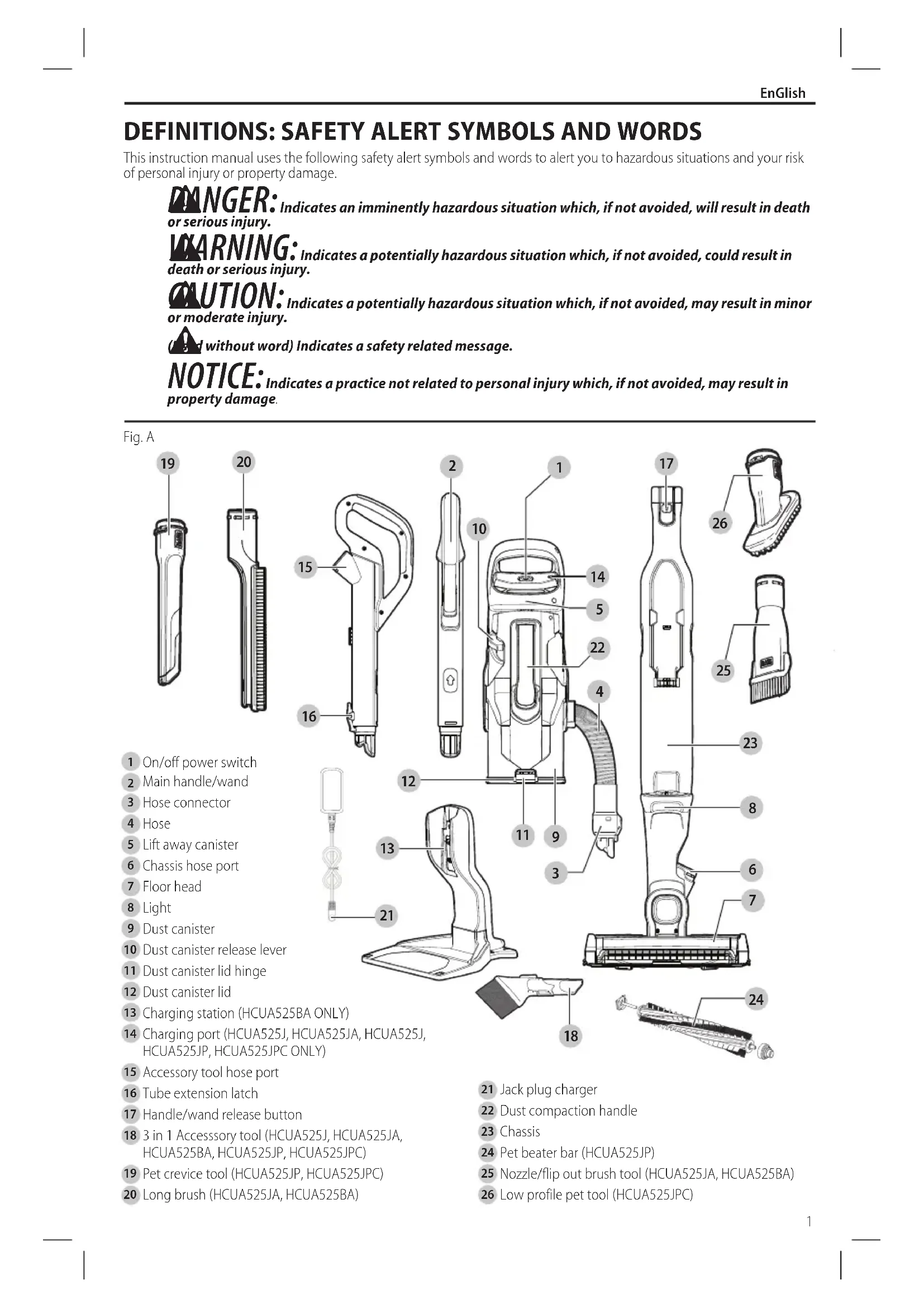
Fig. A
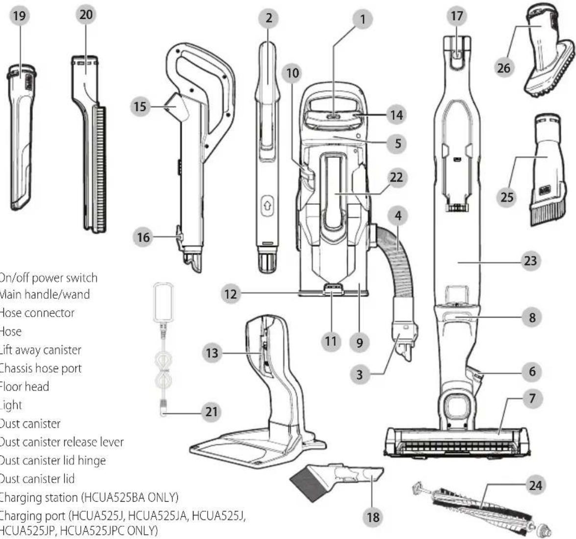
1 On/off power switch
2 Main handle/wand
3 Hose connector
4 Hose
5 Lift away canister
6 Chassis hose port
7 Floor head
8 Light
9 Dust canister
10 Dust canister release lever
11 Dust canister lid hinge
12 Dust canister lid
13 Charging station (HCUA525BA ONLY)
14 Charging port (HCUA525J, HCUA525JA, HCUA525J, HCUA525JP, HCUA525JPC ONLY)
15 Accessory tool hose port
16 Tube extension latch
17 Handle/wand release button
18 3 in 1 Accessory tool (HCUA525J, HCUA525JA, HCUA525BA, HCUA525JP, HCUA525JPC)
19 Pet crevice tool (HCUA525JP, HCUA525JPC)
20 Long brush (HCUA525JA, HCUA525BA)
21 Jack plug charger
22 Dust compaction handle
23 Chassis
24 Pet beater bar (HCUA525JP)
25 Nozzle/flip out brush tool (HCUA525JA, HCUA525BA)
26 Low profile pet tool (HCUA525JPC)
EnGlish
WARNING! Read all safety warnings
and all instructions. Failure to follow the warnings and instructions may result in electric shock, fire and/or serious injury.

WARNING: To reduce the risk of injury, read the instruction manual.
IMPORTANT SAFETY INSTRUCTIONS
When using an electrical appliances, basic precautions should always be followed, including the following:
READ ALL INSTRUCTIONS BEFORE USING THIS APPLIANCE.
WARNING: Read all safety warnings
and all instructions. Failure to follow the warnings and instructions listed below may result in electric shock, fire and/or serious injury.
WARNING: Some household dust contains chemicals known to the State of California to cause cancer, birth defects or other reproductive harm such as asbestos and lead in lead based paint.
WARNING: Do not attempt to modify or repair the appliance.
WARNING: Do not charge the battery at ambient temperatures below 39 °F (4 °C) or above 104 °F (40 °C). Follow all charging instructions and do not charge the appliance outside of the temperature range specified in the instructions. Charging improperly or at temperatures outside of the specified range may damage the battery and increase risk of fire.
WARNING: To reduce the risk of fire, electrical shock or injury:
- Shock Hazard. To protect against risk of electrical shock, do not put charging base in water or other liquid.
- Do not allow to be used as a toy. Close attention is necessary when used by or near children.
- Use only as described in this manual. Use only manufacturer's recommended attachments.
-
Do not use with damaged cord or plug. If appliance is not working as it should, has been dropped, damaged, left outdoors, or dropped into water, return it to a service center.
-
Do not pull or carry by cord, use cord as a handle, close a door on cord, or pull cord around sharp edges or corners. Do not run appliance over cord. Keep cord away from heated surfaces.
- Do not unplug by pulling on cord. To unplug, grasp the plug, not the cord.
- Do not handle charger, including charger plug, and charger terminals with wet hands.
- Do not put any object into openings. Do not use with any opening blocked; keep free of dust, lint, hair, and anything that may reduce air flow.
- Keep hair, loose clothing, fingers, and all parts of body away from openings and moving parts.
- Use extra care when cleaning on stairs.
- Do not use to pick up flammable or combustible liquids, such as gasoline, or use in areas where they may be present.
- Do not pick up anything that is burning or smoking, such as cigarettes, matches, or hot ashes.
- Do not use without dust bag and/or filters in place.
- Do not charge the unit outdoors.
- Use only the charger supplied by the manufacturer to recharge.
- Do not incinerate the appliance even if it is severely damaged. The batteries can explode in a fire.
- This appliance is intended for household use only and not for commercial or industrial use.
- Do not allow the cord to hang over the edge of a table or counter or touch hot surfaces. The unit should be placed or mounted away from sinks and hot surfaces.
- Plug the charger directly into an electrical outlet.
- Use the charger only in a standard electrical outlet (120V/60Hz).
- Unplug the charger from outlet before any routine cleaning or maintenance.
- Do not look into the air vents when the unit is switched on, as sometimes there is a possibility of small debris being discharged from the air vents, especially after cleaning / replacement of the filters as debris inside the unit can be disturbed.
- Leaks from battery cells can occur under extreme conditions. If the liquid, which is a 20 - 35% solution of potassium hydroxide, gets on the skin (1) wash quickly with soap and water or (2) neutralize with a mild acid such as lemon juice or vinegar. If the liquid gets into the eyes, flush them immediately with clean water for a minimum of 10 minutes. Seek medical attention.
ADDITIONAL SAFETY WARNINGS
a) Prevent unintentional starting. Ensure the switch is in the off-position before picking up or carrying the appliance. Carrying the appliance with your finger on the switch or energizing appliance that have the switch on invites accidents.
b) Recharge only with the charger specified by the manufacturer. A charger that is suitable for one type of battery pack may create a risk of fire when used with another battery pack.
c) Do not use a battery pack or appliance that is damaged or modified. Damaged or modified
batteries may exhibit unpredictable behavior resulting in fire, explosion or risk of injury.
d) Do not expose a battery pack or appliance to fire or excessive temperature. Exposure to fire or temperature above 266 °F (130 °C) may cause explosion.
e) Have servicing performed by a qualified repair person using only identical replacement parts. This will ensure that the safety of the product is maintained.
f) Only for use with S010QU2300040 and SSC-230040US chargers.
EMC requirements for all digital devices
This device complies with Part 15 of the FCC Rules and Industry Canada License-exempt RSS standard(s). Operation is subject to the following two conditions:
- This device may not cause harmful interference, and
- This device must accept any interference received, including interference that may cause undesired operation.
Changes or modifications not expressly approved by the party responsible for compliance could void the user's authority to operate the equipment.
This equipment has been tested and found to comply with the limits for a Class B digital device, pursuant to Part 15 of the FCC Rules. These limits are designed to provide reasonable protection against harmful interference in a residential installation. This equipment generates, uses, and can radiate radio frequency energy and, if not installed and used in accordance with the instructions, may cause harmful interference to radio communications. However, there is no guarantee that interference will not occur in a particular installation. If this equipment does cause harmful interference to radio or television reception, which can be determined by turning the equipment off and on, the user is encouraged to try to correct the interference by one of the following measures:
- Reorient or relocate the receiving antenna.
- Increase the separation between the equipment and receiver.
- Connect the equipment into an outlet on a circuit different from that to which the receiver is connected.
- Consult the dealer or an experienced radio/TV technician for help.
CAN ICES-3(B)/NMB-3(B)
SAVE THESE INSTRUCTIONS
SYMBOLS
The label on your tool may include the following symbols. The symbols and their definitions are as follows:
V....volts
A.....amperes
Hz......hertz
W.....watts
min......minutes
\~ or AC......alternating current
= -- = or DC......direct current
n_0 no load speed
Class I Construction (grounded)
earthing terminal
A safety alert symbol
☐ Class II Construction (double insulated)
.../min or rpm. revolutions or reciprocation per minute
Wh.....Watt Hours
ASSEMBLY
WARNING:
Do not attempt to modify or
repair the appliance.
Intended use
Your BLACK+DECKER lithium ion cordless 2 in 1 canister stick vacuum cleaner has been designed for light dry vacuum cleaning purposes. This appliance is intended for household use only.
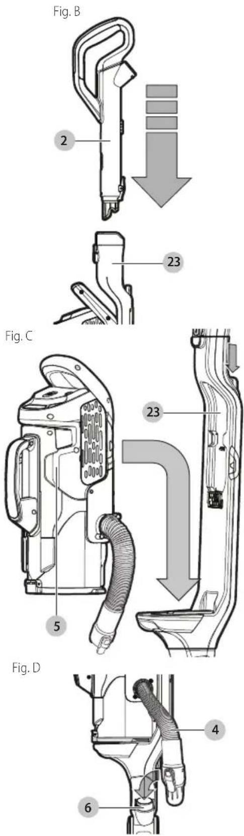
Assembly (Fig. A, B–D)
- Align the main handle/wand 2 to the chassis 23 as shown in Figure B.
- Push the main handle/wand 2 into the chassis 23 as shown in Figure B.
- Fit the lift away canister 5 to the chassis 23 so it locks into place as shown in Figure C.
- Fit the hose 4 to the chassis hose port 6 as shown in Figure. D.
- To stand the unit upright, angle the chassis forward so that it is standing straight up. The floor head 7 will hold the chassis in place.
WARNING:
When not in use position the
upright unit with the rear of the chassis facing a wall so that any inadvertent fall of the unit would contact a wall and not people or pets.
EnGlish
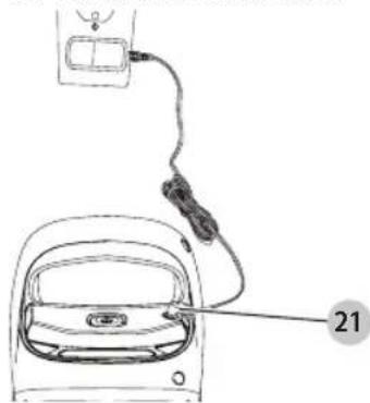
Charging the battery (HCUA525J, HCUA525JA, HCUA525J, HCUA525JP)

RNING:
For use only with the
supplied charger.
From new, the rechargeable cells of the product need a minimum charge time of 6 hours to ensure full power.
- The unit must be turned off in order to charge.
• Figure E - Plug the jack plug 21 of the charger into the charging port 14 of the tool. Plug the charger into any standard 120 Volt 60 Hz electrical outlet.
Fig. E
natural_image
Line drawing of a car interior with a cable and connector, labeled with number 21 (no text or symbols on the diagram itself)
- While charging, the charger may get warm, this is perfectly normal and safe. It is safe to leave the appliance connected to the charger indefinitely. The charger automatically reduces power consumption when charging is complete.
| Battery Sensor LED Patterns |
| Battery Fault (All LEDs) |
| Charger Fault (All LEDs) |
| Battery Hot (All LEDs) |
WARNING:
Do not charge the battery is below 39 °F (4 °C) or above charging instructions and do outside of the temperature instructions. Charging features outside of the specified battery and increase risk
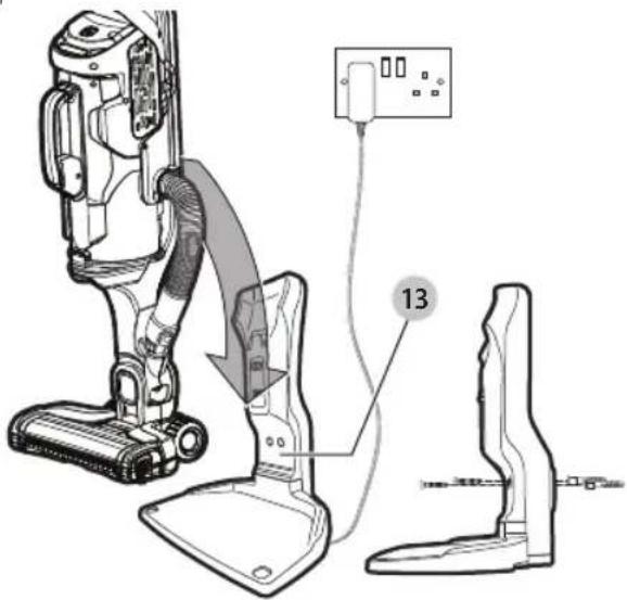
Charging the battery (HCUA525BA)
WARNING:
For use only with the
supplied charger.
- Before first use, the battery must be charged for at least 6 hours.
- Place the appliance on the charging station 13 whenever it is not in use as shown in Figure F.
Plug the charger into any standard 120 Volt 60 Hz electrical outlet. The LED charging indicator will flash and increase in sections. LEDs go out when fully charged.
NOTE: The charging base is supplied with 2 screws and wall plugs for securing it to a wall, providing extra stability, as shown in Figure F.
| Battery Sensor LED Patterns |
| Battery Fault (All LEDs) |
| Charger Fault (All LEDs) |
| Battery Hot (All LEDs) |
WARNING:
Before charging, be sure to
empty all contents and dry thoroughly if needed to avoid damage to your appliance.
• The unit must be turned off in order to charge.
NOTE: While charging, the charger may become warm. This is normal and does not indicate a problem. The appliance can be left connected to the charger indefinitely.
Fig. F
WARNING:
Do not charge the battery
at ambient temperatures below 39 °F (4 °C) or above 104 °F (40 °C). Follow all charging instructions and do not charge the appliance outside of the temperature range specified in the instructions. Charging improperly or at temperatures outside of the specified range may damage the battery and increase risk of fire.
USE
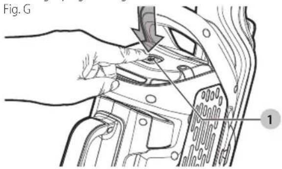
Switching on and off (Fig. G)
- To switch ON, press the on/off switch 1. The state of charge indicator LEDs will illuminate and vacuum will begin in AUTOSENSE mode.
nOTE: Unit starts in mid performance setting.
• To switch OFF, press the on/off switch 1.
- Return the product to the charger immediately after use so that it will be ready and fully charged for the next use. Ensure that the product is fully engaged with the charger plug or charger base.
State of charge indicator
This appliance include a state of charge indicator which consists of three white LED lights that indicate the level of charge remaining in the battery. This feature is only activated when the vacuum is powered on.
The state of charge indicator is an indication of approximate levels of charge remaining in the battery pack according to the following indicators:

75–100% charged

51–74% charged

< 50% charged
The LED battery indicator displays the remaining charge and warns you when the battery is low. The final LED will flash continuously when there is only 1 minute of runtime remaining. All LEDs will flash when the unit is discharged.
NOTE: The state of charge indicator is only an indication of the charge left on the battery. It does not indicate tool functionality and is subject to variation based on product components, temperature and end-user application.
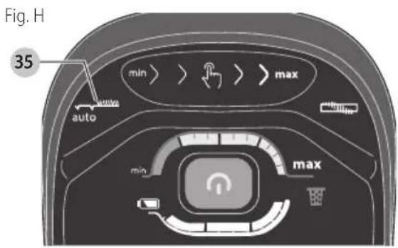
AUTOSENSE (Fig. H)
The appliance is fitted with a unique floor sense feature. It will automatically switch between low and high suction modes as it detects the surface that is being vacuumed.
- The appliance will default to using AUTOSENSE when you turn the unit ON.
• To turn off AUTOSENSE, first turn the unit ON then press the AUTOSENSE button 35 to deactivate the feature.
The features incorporated are:

Intelligent floor sensor technology increases suction on carpets and switches to Economy Mode for lighter tasks, such as hard floor cleaning, thus optimising the battery run time this feature is active when the LED is lit. In order to maximise runtime on all surfaces, switch this feature off by touching area.

Power control Touch Slider
Touch button panel allows you to control the level of power to the unit from minimum to maximum by sliding finger along this area.

Allows you to turn on and off the beater bar function by touching this area.
ENGLISH

State of charge indicator
Allows you to monitor the level of power being used.

BATTERYSENSOR Indicator
The LED battery indicator displays the remaining charge and warns you when the battery is low. The final LED will flash continuously when there is only 1 minute of runtime remaining. All LEDs will flash when the unit is discharged.

FILTERSENSOR
Smart sensor technology automatically detects (the symbol will light red) when the filter becomes clogged and needs to be cleaned.
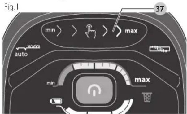
Adjustable suction force (Fig. I)
The appliance has an adjustable suction slider 37. The vacuum can be adjusted to operate at a lower suction level to extend run time or higher suction level to pick up debris that requires more power.
- To increase suction slide your finger on the adjustable suction slider 37 to the right as shown in Figure I. Corresponding LEDs on the min/max indicator will display the selected suction force.
- To decrease suction slide your finger on the adjustable suction slider 37 to the left.
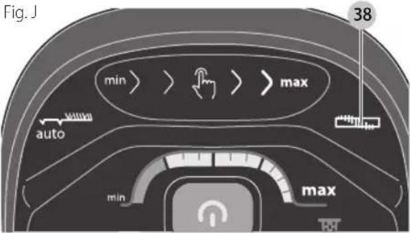
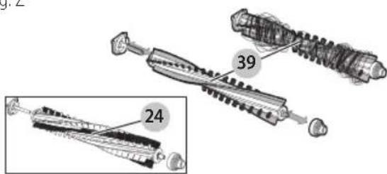
Powered rotary brush and LED (Fig. J, Z)
• To engage the rotary brush 39 (Fig. Z) inside the floor head 7, depress the rotary brush ON/OFF button 38 as shown in Figure J. When the rotary brush is ON the LED work light will illuminate to better see debris as you vacuum.
• To disengage the rotary brush 39, depress the rotary brush ON/OFF button 38 a second time.
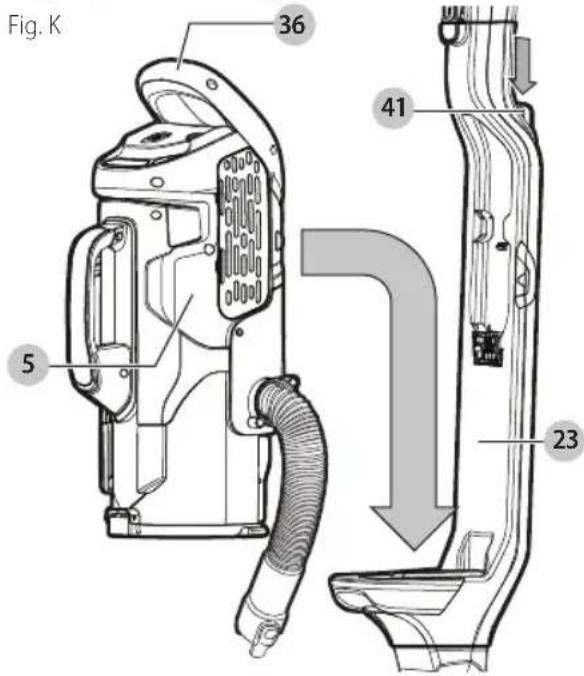
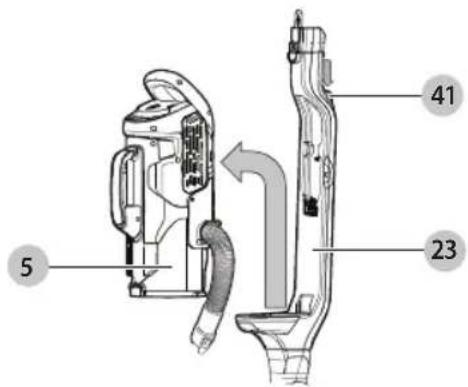
Removing and attaching the lift away canister (Fig. K, L)
• To remove the lift away canister from the chassis, press the lift away canister release button 41 to release the lift away canister 5 from the chassis 23 hold the lift away handle 36 and lift out the lift away canister 5 as shown in Figure K.
- Release the hose connector 3 from the chassis hose port 6 as shown in Figure L.
- To attach the lift away canister to the chassis, hold the main lift off handle 36 and place the lift away canister 5 onto the chassis and slide downward so the canister locks into position as shown in Figure K.
- Connect the hose connector 3 to the chassis hose port 6 as shown in Figure L.
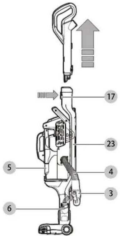
EnGlish
- Press the main handle/wand release button 17 to free the main handle/wand from the chassis 23.
- Free the hose connector 3 from the main body hose port 6 as shown in Figure L.
Fig. L
- Press the lift away canister release button 41 to release and remove the lift away canister 5 from the chassis 23 as shown in Figure M.
Fig. M
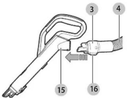
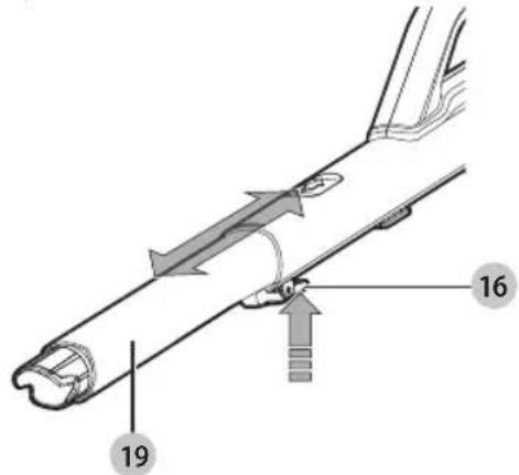
- Connect the hOSE CONNECTOR 3 TO THE ACCESSORY TOOL HOSE PORT 15 ENSURING THAT THE LATCH 16 CLICKS SECURELY INTO PLACE AS SHOwn in Figure N.
Fig. N
- Extend the crevice tool 19 as shown in Figure O, until it clicks in place.
- To retract the crevice tool 19 press the crevice tool release button 16 allowing it to return to its normal position.
Fig. O
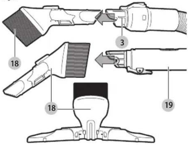
• The 3-in-1 accessory tool 18 has three configurations.
- Brush mode.
- Small crevice mode.
- Upholstery mode.
- The 3-in-1 accessory tool can be fitted either directly to the hose connector 3 or to the pet crevice tool 19 as shown in Figure P.
Fig. P
Cleaning and emptying the vacuum
WARNING: Projectile/Respiratory Hazard:
Never use the vac without its filter.
NOTE: The filter is re-usable, do not confuse it with a disposable dust bag, and do not throw it away when the product is emptied. We recommend that you replace the filter every 6–9 months depending on frequency of use. There are two methods of cleaning the canister, a quick empty method and a thorough clean method.
To empty the dust canister (Fig. L, M, Q, R)
- Press the life away canister release button 41 to release and remove the lift away canister 5 from the chassis 23 as shown in Figure M.
EnGlish
- Release the hose connector 3 from the main body hose port 6 as shown in Figure L.
Fig. Q
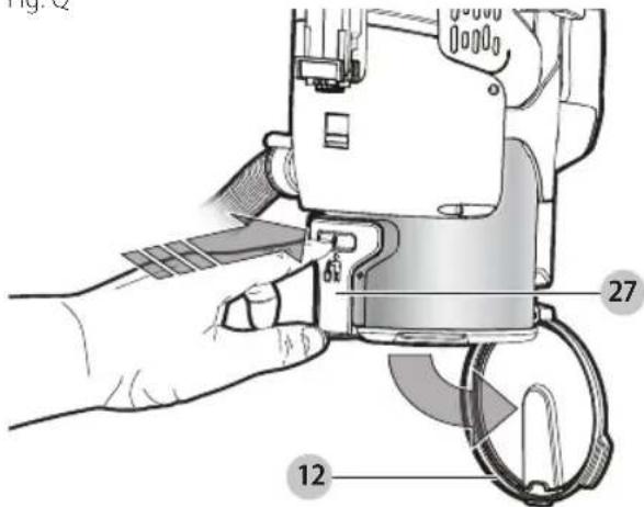
- Place the dust canister over a trash bin and press the dust canister lid release button 27 to empty the canister as shown in Figure Q.
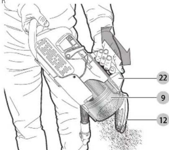
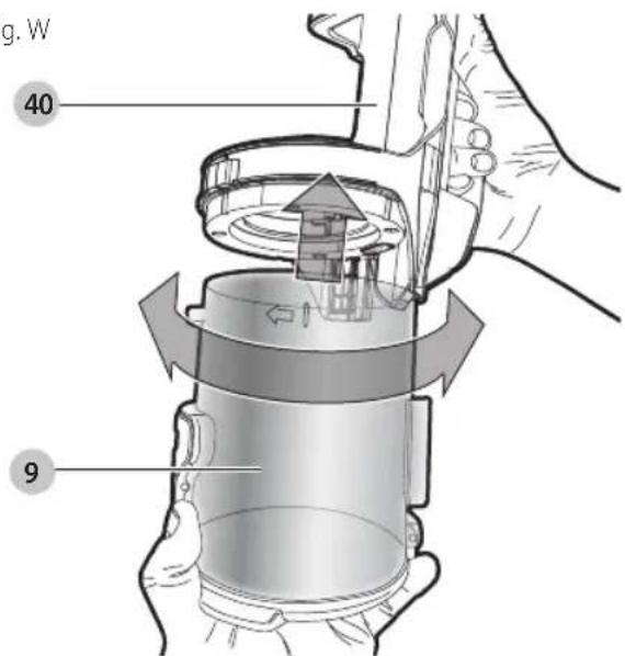
- Push the compaction handle 22 down to empty the contents of the dust canister 9 as shown in Figure R.
NOTE: The dust compaction handle 22 can also be used to compact the contents of the dust canister 9, doubling the capacity of the dust canister.
- Close the dust canister lid 12, until it "clicks" firmly into position.
Compacting the contents of the dust canister (Fig. R)
With the dust canister lid 12 closed, push the compacting handle 22 down to compact the contents of the dust canister 9 thus increasing its capacity as shown in Figure R.
Fig. R
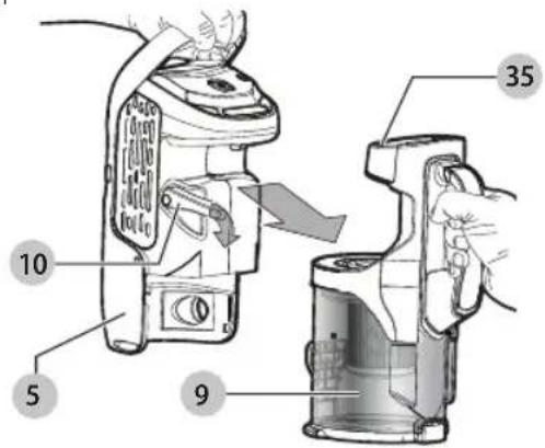
Releasing the dust canister (Fig. R-T)
NOTE: The dust canister can be released either from the unit while it is in chassis mode, as shown in Figure S, or when being used in the lift away canister vac mode, as shown in Figure T.
- Press the dust canister release lever 10 down to release the dust bowl.
- Free the dust canister 9 from the lift away canister vac 5.
NOTE: The catch 34 ensures that the unit will be unable to start when the dust canister 9 is not connected to the lift away canister vac 5 or when the compaction handle 22 is in operation.
- Using the dust canister handle 35 and holding the unit over a suitable waste receptacle, press the dust canister release button 27 to release the dust canister lid 12 and push the compacting handle 22 down to empty the contents of the dust canister 9 as shown in Figure R.
Fig. S
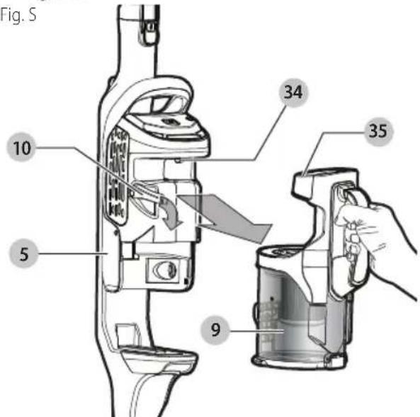
Fig. T
Cleaning the filters (Fig. S-X)
- Press the dust canister release lever 10 down to release the dust canister as shown in Figure S.
- While holding the compaction handle 22, lift the filter assembly 28 from the dust canister 9 by rotating counter-clockwise as shown in Figure U.
NOTE: A scented disc will be provided in foil packaging. This is to be opened and the disc is to be placed in the bottom of the pre-filter allowing for a pleasing odor to be released when the appliance is in use.
Fig. U
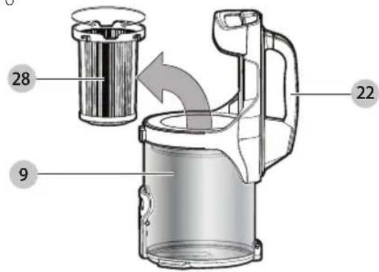
Fig. V
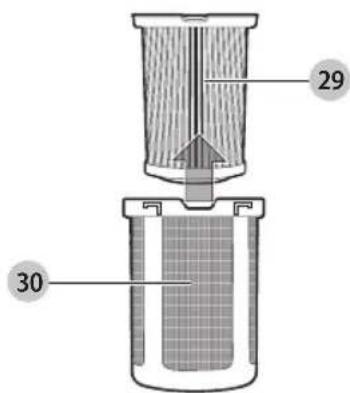
Fig. W
- The dust canister 9 and filter can be washed in warm soapy water. Allow to dry before placing back into the vac.
Fig. X
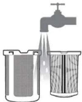
natural_image
Illustration of a water tap spraying water into a container with a mesh filter (no text or symbols)
- Refit the filters into the appliance and ensure that they are correctly seated.
- To replace dust canister, place it back onto the handle until it "clicks" firmly into position.
iIMPORTAnT: Maximum dust collection will only be obtained with a clean filter and an empty dust canister. If dust begins to fall back out of the product after it is switched off, this indicates that the canister is full and requires emptying.
- Wash the filters regularly using warm, soapy water and ensure that it is completely dry before using again. The cleaner the filter is, the better the product will perform.
- It is very important that the filter is correctly in position before use.
Removing and clearing the rotary brushes (Fig. Y, Z)
AUTION:
AUTION: To reduce the risk of injury from moving parts, disconnect lift away canister before cleaning or servicing.
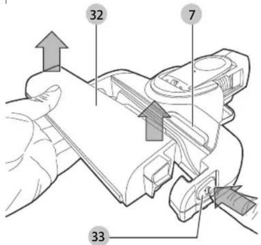
- To remove the rotary brush unit 32 from the floor head 7 Depress the release button 33 as shown in Figure Y. The rotary brush unit will pop up from its locked position.
- The rotary brush 39 can now be removed. The end pieces are also removable allowing you to clear the brushes from any hair or other debris that may have accumulated as shown in Figure Z.
Fig. Y
ENGLISH
Fig. Z
Replacing the filters
The filters should be replaced every 6 to 9 months and whenever worn or damaged. Replacement filters are available from your BLACK+DECKER dealer.
Visit www.blackanddecker.com to locate dealers.
- Remove the old filters as described in Cleaning the Filters.
- Fit the new filters as described in Cleaning the Filters. (cat. no: VSPF10LC)
These fit all units. When these filters reach the end of their lifespan they must be disposed of at a local recycling center. Filters are supplied in foil packaging which needs to be removed prior to use.
Scented filter
BEFORE FIRST USE - remove bag from the scented prefilter. Reassemble per instructions above.
When the vacuum is turned on, the plastic scented filter will emit an aroma to freshen the air.
WARNING:
• Causes mild skin irritation
- Toxic to aquatic life
• Harmful to aquatic life with long lasting effects.
- Dispose of contents/ containers to an approved waste disposal plant.
NOTE: When the plastic scented filter no longer lets off the aroma, it can be an indication that the filter needs to be replaced.
MAINTENANCE
Use only mild soap and damp cloth to clean the vac. Never let any liquid get inside the vac; never immerse any part of the vac into a liquid.
WARNING: Make sure the vacuum is completely dry before using it.
IMPORTANT: To assure product SAFETY and RELIABILITY, repairs, maintenance and adjustment (other than those listed in this manual) should be performed by authorized service centers or other qualified service organizations, always using identical replacement parts.
TROUBLESHOOTING
If the product does not work, check the following:
- The charger was correctly plugged in for recharge. (It feels slightly warm to the touch.)
- The charger cord is not damaged and is correctly attached.
• The charger is plugged into a working electrical outlet.
- The switch is in the "OFF" position when charging. For assistance with your product, visit our website www.blackanddecker.com for the location of the service center nearest you or call the BLACK+DECKER help line at 1-800-544-6986.
ACCESSORIES
Recommended accessories for use with your appliance are available from your local dealer or authorized service center. If you need assistance regarding accessories, please call:
1-800-544-6986.
WARNING: The use of any accessory not recommended for use with this appliance could be hazardous.
All BLACK+DECKER Service Centers are staffed with trained personnel to provide customers with efficient and reliable power tool service. Whether you need technical advice, repair, or genuine factory replacement parts, contact the BLACK+DECKER location nearest you. To find your local service location, call: 1-800-544-6986 or visit
www.blackanddecker.com
TWO-YEAR LIMITED WARRANTY
Black & Decker (U.S.) Inc. warranties this product to be free from defects in material or workmanship for a period of two (2) years following the date of purchase, provided that the product is used in a home environment. This limited warranty does not cover failures due to abuse, accidental damage or when repairs have been made or attempted by anyone other than BLACK+DECKER and its Authorized Service Centers. A defective product meeting the warranty conditions set forth herein will be replaced or repaired at no charge in either of two ways: The first, which will result in exchanges only, is to return the product to the retailer from whom it was purchased (provided that the store is a participating retailer). Returns should be made within the time period of the retailer's policy for exchanges. Proof of purchase may be required. Please check with the retailer for its specific return policy regarding time limits for returns or exchanges. The second option is to take or send the product (prepaid) to a BLACK+DECKER owned or authorized Service Center for repair or replacement at BLACK+DECKER's option. Proof of purchase may be required. BLACK+DECKER owned and authorized service centers are listed online at www.blackanddecker.com. This warranty does not apply to accessories. This warranty gives you specific legal rights and you may have other rights which vary from state to state. Should you have any questions, contact the manager of your nearest BLACK+DECKER Service Center. This product is not intended for commercial use, and accordingly, such commercial use of this product will void this warranty. All other guarantees, express or implied, are hereby disclaimed.
LATIN AMERICA: This warranty does not apply to products sold in Latin America. For products sold in Latin America, check country specific warranty information contained in the packaging, call the local company or see the website for such information.
Imported by Black & Decker (U.S.) Inc.,
701 E. Joppa Rd.
Towson, MD 21286

Charge de la batterie (HCUA525J, HCUA525JA, HCUA525J, HCUA525JP)
natural_image
Line drawing of a device with a cable and labeled component '21' (no text or symbols beyond label)
natural_image
Illustration of a faucet spraying water into two containers (no text or symbols)
natural_image
Line drawing of a car interior with a cable and labeled component (no text or symbols)
EsPAÑOI
natural_image
Illustration of a water tap spraying into two containers with visible flow (no text or symbols)
natural_image
Technical illustration of a mechanical assembly with two components, one showing internal gear-like structure and the other showing external gears (no text or symbols present)
Date of purchase · Fecha de compra Invoice No. · No. de factura
natural_image
Pure geometric lines forming a symmetrical shape with no text, numbers, or symbols

natural_image
Pure horizontal and vertical lines without any text, numbers, or symbols

natural_image
Pure geometric lines forming a symmetrical shape with no text, numbers, or symbols

natural_image
Pure horizontal and vertical lines without any text, numbers, or symbols

natural_image
Pure geometric lines forming a symmetrical shape with no text, numbers, or symbols
SOLAMENTE PARA PROPOSITOS DE MEXICO
Col. Fracc. Universidad
Chihuahua, Chihuahua
Tel. 01 614 413 64 04
Fernando González Armenta
Bolivia No. 605
Col. Felipe Carrillo Puerto
Cd. Madero, Tamaulipas
Tel. 01 833 221 34 50
Black & Decker (U.S.) Inc.
701 East Joppa Road, Towson, MD 21286
Part No. N493459rev02
HCUA525J, HCUA525JA, HCUA525JP, HCUA525BA, HCUA525JPC
JULY 2017