Tread - Gps GARMIN - Free user manual and instructions
Find the device manual for free Tread GARMIN in PDF.
User questions about Tread GARMIN
0 question about this device. Answer the ones you know or ask your own.
Ask a new question about this device
Download the instructions for your Gps in PDF format for free! Find your manual Tread - GARMIN and take your electronic device back in hand. On this page are published all the documents necessary for the use of your device. Tread by GARMIN.
USER MANUAL Tread GARMIN
Arrivee a destination. 48
Considerations relatives au montage. 74
Tread Audio Box Mounting Considerations. 80
Mounting the Tread Audio Box Black Box Device 80
Connections. 80
Identification de port.. 81
Speaker and LED Wiring Harness
Wire and Connector
Identification. 82
RCA Wiring Harness Wire and Connector Identification. 84
Raccordement de l'appareil à l'alimentation du vehicule. 85
Using the Heat-Shrink Crimp Connectors. 86
Complete System Wiring. 86
Zones de haut-parleurs. 88
Single-Zone System Wiring Example. 88
Tread 6.5" XS-LED Tower Speakers -
Bracket Side Dimensions. 98
Bracket Top Dimensions. 98
Cameras sans fil. 98
Considerations relatives au montage
Application Tread Audio
Arrivee a destination
Considerations relatives au montage
You can use a connected Tread Audio system to control audio and LED lights from your Tread device.
Tread Audio Box Mounting Considerations
ATTENTION
In high ambient temperatures and after extended use, the device enclosure may reach temperatures deemed dangerous to touch. Therefore, you must install the device in a location where it is not touched during operation.
AVIS
The storage and operating temperature ranges for this device are listed in the product specifications. Extended exposure to temperatures exceeding the specified temperature range, in storage or operating conditions, may cause device failure. Device damage and related consequences caused by extended exposure to these conditions are not covered by the warranty.
- You must mount the device in a location with adequate ventilation where it is not exposed to extreme temperatures.
- You should mount the device so that the cables can be connected easily.
To achieve IP67 water ingress protection and optimal heat sink cooling, you must mount the device on a vertical surface with the connectors pointing downward. - You can mount the device on a horizontal surface, but such positioning might not achieve IPX67 water ingress protection.
- To avoid interference with a magnetic compass, you should install the device at least 203mm (8 in.) away from a compass.
Mounting the Tread Audio Box Black Box Device
Before you mount the device, you must select a mounting location, and determine what screws and other mounting hardware are needed for the surface.
1 Place the black box device in the mounting location, and mark the location of the pilot holes.
2 Drill a pilot hole for one corner of the device.
3 Loosely fasten the device to the mounting surface with one corner, and examine the other three pilot-hole marks.
4 Mark new pilot-hole locations if necessary, and remove the device from the mounting surface.
5 Drill the remaining pilot holes.
6 Secure the device to the mounting location.
Connections
The stereo must be connected to power, to speakers, and to media input sources to function correctly. You should carefully plan the layout of the stereo, speakers, and your input sources before making any connections.
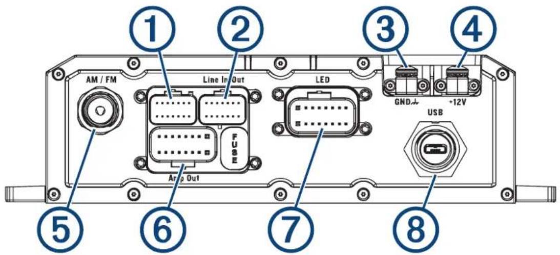
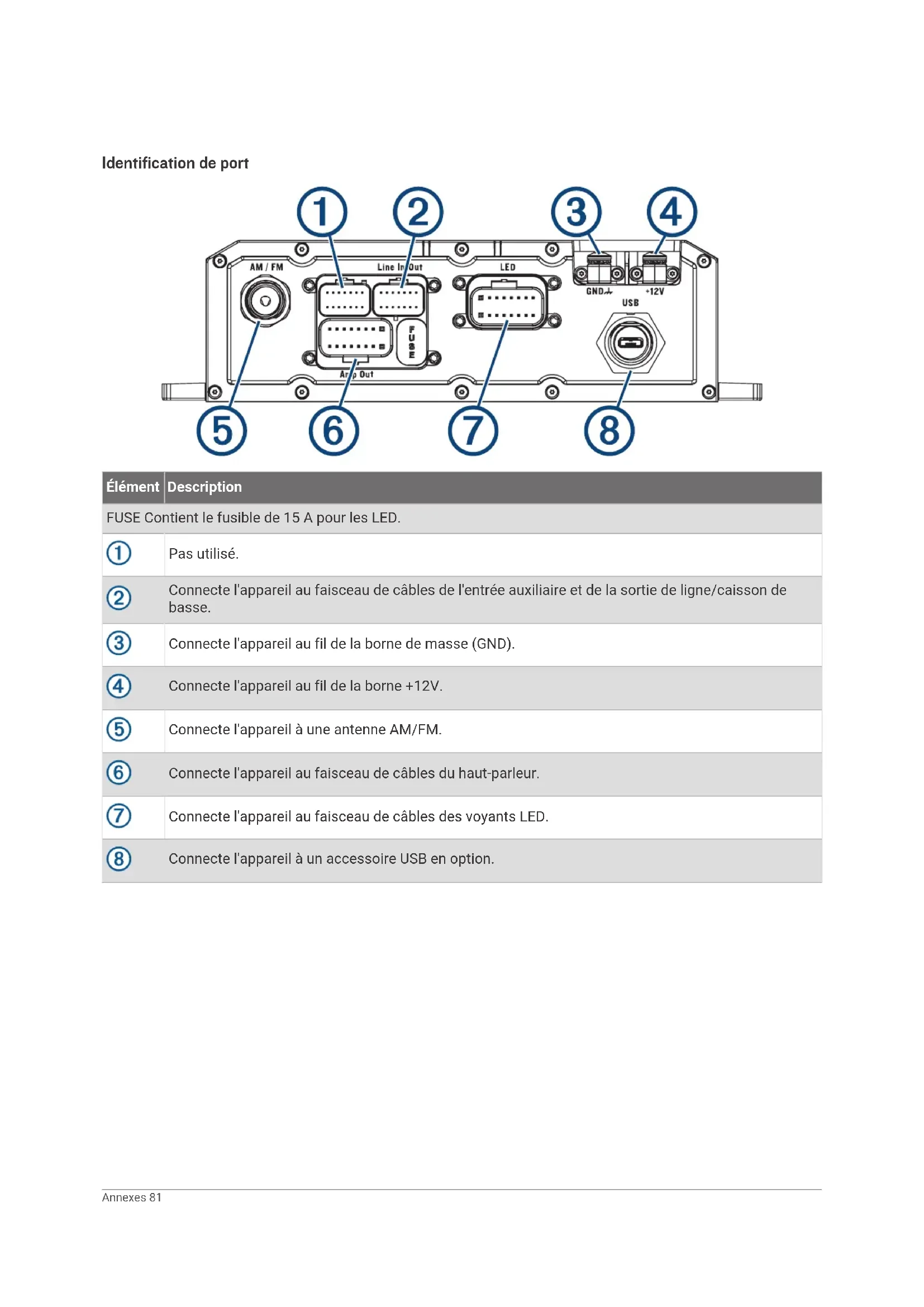
Identification de port
Element
Description
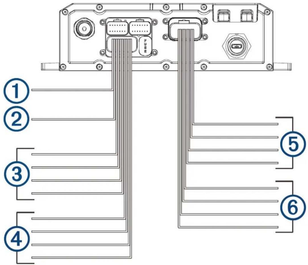
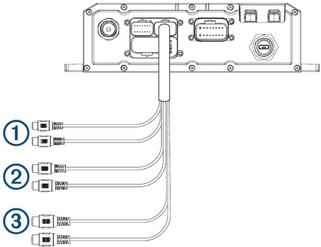
Speaker and LED Wiring Harness Wire and Connector Identification
| Wire Group Wire Color and Description | |
| ① Ignition | Red: Connects to the vehicle accessory line. If the ignition wire is unused, ground the ignition wire or leave it disconnected. |
| ② Amplifier on | Blue: Connects to an optional external amplifier to turn it on when the stereo turns on. |
| ③ Speaker zone 1 | White: Left (+), Connects to the included speaker. White with a black stripe: Left (-), Connects to the included speaker. Gray: Right (+), Connects to the included speaker. Gray with a black stripe: Right (-), Connects to the included speaker. |
| ④ Speaker zone 2 | Green: Left (+), Connects to an additional speaker. Green with a black stripe: Left (-), Connects to an additional speaker. Purple: Right (+), Connects to an additional speaker. Purple with a black stripe: Right (-), Connects to an additional speaker. |
| ⑤ LED RGB1 | Black: Power Red: Red LED Green: Green LED Blue: Blue LED |
| ⑥ LED RGB2 | Black: Power Red: Red LED |
Wire Group Wire Color and Description
Green: Green LED
Blue: Blue LED
Addressable LED Wiring Considerations
You can wire addressable LED lights to your Tread Audio Box. For more information, see the manual for your addressable LED lights.
Compatible addressable LED types:
·WS2812B
·WS2813
Addressable LED LED Wire Color and Function
Addressable LED 1
Red: +5V Power
White: Ground
Green with a black stripe: Data
Addressable LED 2
Red: +5V Power
White: Ground
Green with a black stripe: Data
RCA Wiring Harness Wire and Connector Identification
| Wire Number | Wire Function |
| ① | Auxiliary in left: Provides a red and white RCA stereo line input for audio sources, such as a CD or MP3 player. Auxiliary in right: Provides a red and white RCA stereo line input for audio sources, such as a CD or MP3 player. |
| ② | Line out left: Provides a full-range output to an external amplifier, and is associated with the volume control. Line out right: Provides a full-range output to an external amplifier, and is associated with the volume control. REMARQUE: if you are connecting to an external amplifier, you should use a ground loop isolator to ensure a clear signal. |
| ③ | Subwoofer out: Provides a single mono output to a powered subwoofer or subwoofer amplifier. REMARQUE: if you are connecting to an external amplifier, you should use a ground loop isolator to ensure a clear signal. |
Using the Heat-Shrink Crimp Connectors
You should use the included heat-shrink crimp connectors to make a water-tight connection between the bare wires.
AVERTISSEMENT
Only use the heat gun to apply heat to the heat-shrink crimp connectors in a well-ventilated area. Do not use the heat gun near clothing or bare skin. Doing so can result in property damage or serious injury.
1 Using wire strippers, strip 6 mm ( 1 / 4 in.) off the end of each bare wire.
2 If necessary, twist the strands of each wire clockwise to bundle them together.

3 Insert one bare wire into one end of the heat-shrink crimp connector. ②
The bare wires are not secure until they are crimped and sealed.
4 Insert the corresponding bare wire into the other end of the heat-shrink crimp connector.
5 Using pliers, crimp both sides of the center of the connector ⑧ secure the connection.
6 Using a heat gun, apply heat to the heat-shrink crimp connector until the connector is sealed to the wires.
Do not apply heat to the wires directly.
Complete System Wiring
This diagram illustrates a system installation with an external amplifier and subwoofer connected to the stereo using a line out.
REMARQUE: you can also connect speakers to the speaker wires for the internal stereo amplifier while using an external amplifier connected to the line out. Adjusting the volume affects speakers connected to the internal amplifier and speakers connected to the line out. This may result in uneven volume levels.
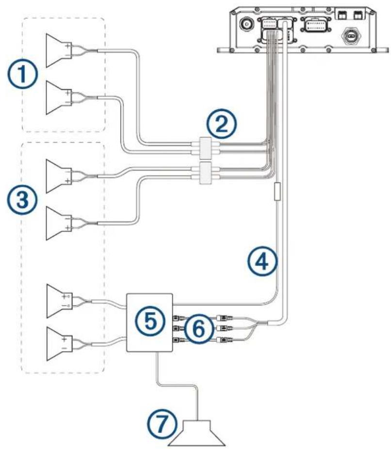
| Item Description | |
| ① | Zone 2 speakers |
| ② | Water-tight connection |
| ③ | Zone 1 speakers |
| ④ | Amplifier-on signal wire |
| ⑤ | Powered amplifier |
| ⑥ | Line out and subwoofer out |
| ⑦ | Subwoofer |
Water-tight connection
When connecting the speakers and LED lights to your stereo or amplifier, observe these considerations.
- You should use the included wire to connect the speakers to the stereo or amplifier. If necessary, you can use a larger gauge of wire (Wire Gauge Guide, page 92).
- You should make all of the wiring connections using the included heat-shrink crimp connectors. You should plan and select the best connection type for your installation needs.
- You can use this table to identify the polarity of the leads on the speaker.
| Lead color Polarity Use | |
| White Positive (+) Speaker | |
| White with a black stripe Negative (-) Speaker | |
| Red Red LED | |
| Green Green LED | |
| Blue Blue LED | |
| Black +12V Power | |
Wire Gauge Guide
If necessary, you can use longer cables for your installation.
REMARQUE: if you are using aluminum or tinned wire, you should use a wire two gauges larger than the gauge listed below to compensate for a potential voltage drop due to the wire material.
- Use 16 AWG (1.31 mm²) for speaker wires.
- Use 20 AWG (0.52 mm²) for LED wires.
Bracket Side Dimensions
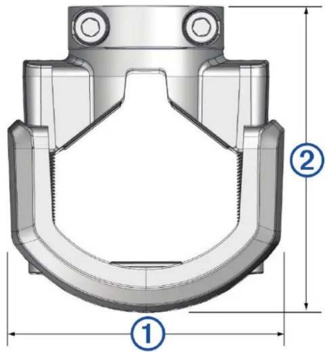
(1)
85 mm (3^3 / 8 in.)
(2)
From 74mm (2^7 / 8 in.) to 94mm (3^11 / _16 in.)
Bracket Top Dimensions
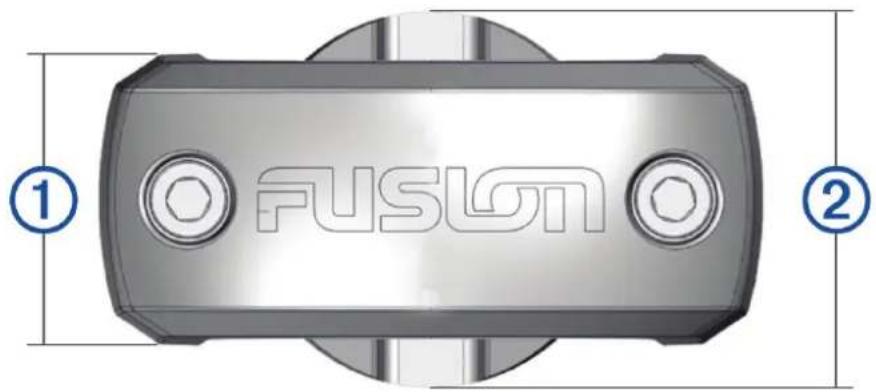
(1)
37 mm (1^7 / _16 in.)
(2)
48 mm (2 in.)