DLARS60U3D - Projector JVC - Free user manual and instructions
Find the device manual for free DLARS60U3D JVC in PDF.
| Product type | D-ILA home cinema projector |
| Model | DLA-RS60 (DLARS60U3D) |
| Brand | JVC |
| Display technology | 3 D-ILA 0.7" panels (1920 x 1080 pixels each) |
| Lens | Motorized zoom 2.0x (1.4:1 to 2.8:1), motorized focus, motorized lens shift |
| Light source | 220 W high-pressure mercury lamp (PK-L2210U) |
| Lamp life | Approximately 3000 hours (normal mode) |
| Screen size | 60" to 200" (16:9) |
| Projection distance | 1.78 m to 12.30 m |
| Native resolution | 1920 x 1080 (Full HD) |
| Video inputs | HDMI (x2), Component (RCA x3), PC (D-Sub 15) |
| Other connections | RS-232C, LAN (RJ-45), 3D Sync, Trigger (12 V DC) |
| 3D functions | THX 3D certified, compatible with PK-AG1-B active glasses and PK-EM1 emitter |
| Image modes | Film, Cinema, Animation, Natural, Scene, THX, User 1/2/3 |
| Power supply | AC 110-240 V, 50/60 Hz |
| Power consumption | 350 W (standby: 0.9 W) |
| Dimensions (W x H x D) | 455 x 179 x 472 mm (without feet or lens) |
| Weight | 15.1 kg |
| Operating temperature | 5 °C to 35 °C |
| Operating humidity | 20% to 80% (non-condensing) |
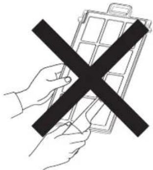
| Cleaning | Cabinet: soft damp cloth; lens: blower or optical tissue; filter: vacuum or wash |
| Spare parts | Replacement lamp (PK-L2210U), replacement filter (PC010661199) |
| Ceiling mounting | Possible, use M5 screws (max depth 23 mm) |
| Safety | Mandatory grounding, do not block ventilation, do not look into lens |
| Certifications | THX 3D, ISFccc, HDMI 1.4a compatible |
Frequently Asked Questions - DLARS60U3D JVC
User questions about DLARS60U3D JVC
0 question about this device. Answer the ones you know or ask your own.
Ask a new question about this device
Download the instructions for your Projector in PDF format for free! Find your manual DLARS60U3D - JVC and take your electronic device back in hand. On this page are published all the documents necessary for the use of your device. DLARS60U3D by JVC.
USER MANUAL DLARS60U3D JVC
© 2010 Victor Company of Japan. Limited
0710TTH-AO-AO
DLA-RS40 DLA-RS50 DLA-RS60
D-ILA PROJECTOR PROJECTEUR D-ILA PROYECTOR D-ILA
natural_image
Line drawing of a projector with front panel and control buttons (no text or symbols)


DISPLAY

For Customer use :
Enter below the serial No. which is located on the side of the cabinet. Retain this information for future reference.
DLA-RS40 Model No. DLA-RS50 DLA-RS60
Serial No.
This product has a High Intensity Discharge (HID) lamp that contains mercury.
Disposal of these materials may be regulated in your community due to environmental considerations. For disposal or recycling information, please contact your local authorities or for USA, the Electronic Industries Alliance: http://www.eiae.org.
WARNING:
TO PREVENT FIRE OR SHOCK HAZARDS, DO NOT EXPOSE THIS APPLIANCE TO RAIN OR MOISTURE.
WARNING:
THIS APPARATUS MUST BE EARTHED.
CAUTION:
To reduce the risk of electric shock, do not remove cover. Refer servicing to qualified service personnel.
This projector is equipped with a 3-blade grounding type plug to satisfy FCC rule. If you are unable to insert the plug into the outlet, contact your electrician.
MACHINE NOISE INFORMATION (Germany only)
Changes Machine Noise Information Ordinance 3. GSGV, January 18, 1991: The sound pressure level at the operator position is equal or less than 20 dB (A) according to ISO 7779.
FCC INFORMATION (U.S.A. only)
CAUTION:
Changes or modification not approved by JVC could void the user's authority to operate the equipment.
NOTE:
This equipment has been tested and found to comply with the limits for Class B digital devices, pursuant to Part 15 of the FCC Rules. These limits are designed to provide reasonable protection against harmful interference in a residential installation. This equipment generates, uses, and can radiate radio frequency energy and, if not installed and used in accordance with the instructions, may cause harmful interference to radio communications. However, there is no guarantee that interference will not occur in a particular installation. If this equipment does cause harmful interference to radio or television reception, which can be determined by turning the equipment off and on, the user is encourage to try to correct the interference by one or more of the following measures:
and receiver.
circuit different from that to which the receiver is connected.
TV technician for help.
About the installation place
Do not install the projector in a place that cannot support its weight securely.
If the installation place is not sturdy enough, the projector could fall or overturn, possibly causing personal injury.
IMPORTANT SAFEGUARDS
Electrical energy can perform many useful functions. This unit has been engineered and manufactured to assure your personal safety. But IMPROPER USE CAN RESULT IN POTENTIAL ELECTRICAL SHOCK OR FIRE HAZ ARD.
In order not to defeat the safeguards incorporated into this product, observe the following basic rules for its installation, use and service. Please read these Important Safeguards carefully before use.
- All the safety and operating instructions should be read before the product is operated.
-
The safety and operating instructions should be retained for future reference.
-
All warnings on the product and in the operating instructions should be adhered to.
- All operating instructions should be followed.
- Place the projector near a wall outlet where the plug can be easily unplugged.
- Unplug this product from the wall outlet before cleaning. Do not use liquid cleaners or aerosol cleaners. Use a damp cloth for cleaning.
- Do not use attachments not recommended by the product manufacturer as they may be hazardous.
- Do not use this product near water. Do not use immediately after moving from a low temperature to high temperature, as this causes condensation, which may result in fire, electric shock, or other hazards.
- Do not place this product on an unstable cart, stand, or table. The product may fall, causing serious injury to a child or adult, and serious damage to the product. The product should be mounted according to the manufacturer's instructions, and should use a mount recommended by the manufacturer.
- When the product is used on a cart, care should be taken to avoid quick stops, excessive force, and uneven surfaces which may cause the product and cart to overturn, damaging equipment or causing possible injury to the operator.
- Slots and openings in the cabinet are provided for ventilation. These ensure reliable operation of the product and protect it from overheating. These openings must not be blocked or covered. (The openings should never be blocked by placing the product on bed, sofa, rug, or similar surface. It should not be placed in a built-in installation such as a bookcase or rack unless proper ventilation is provided and the manufacturer's instructions have been adhered to.)
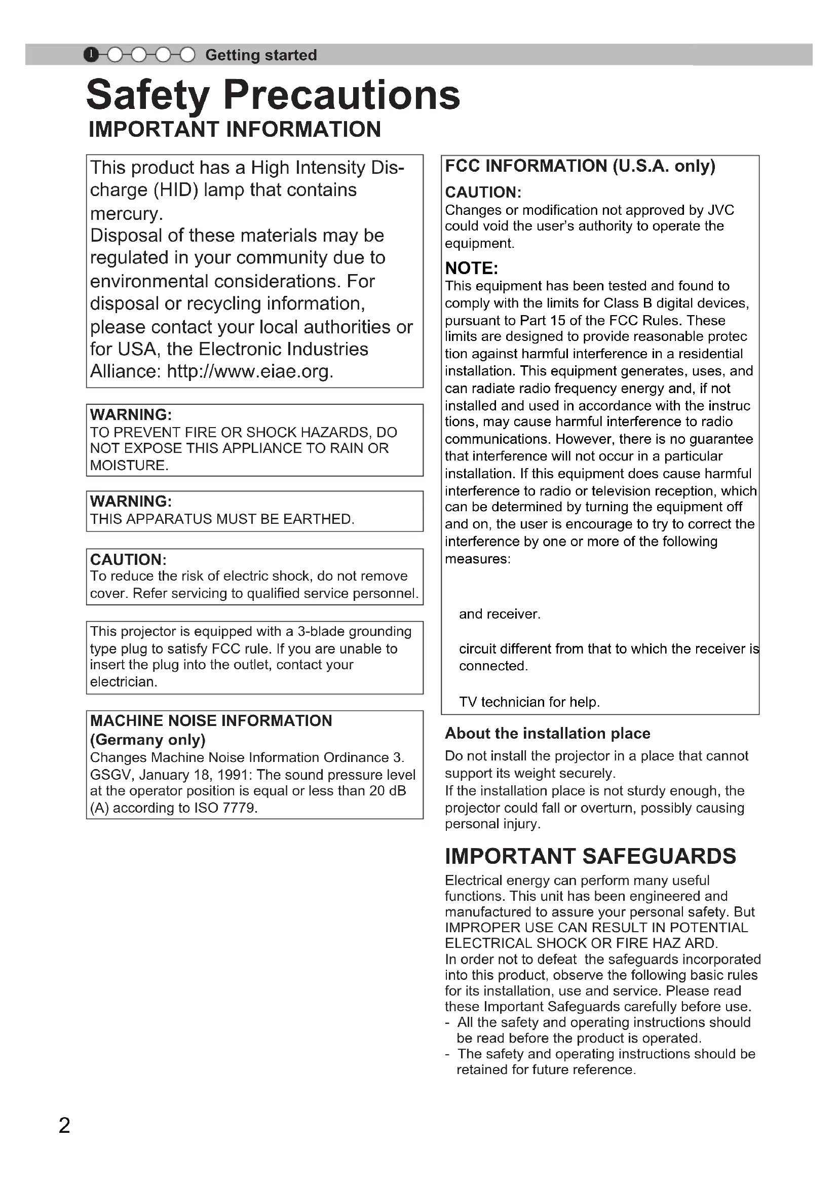
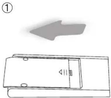
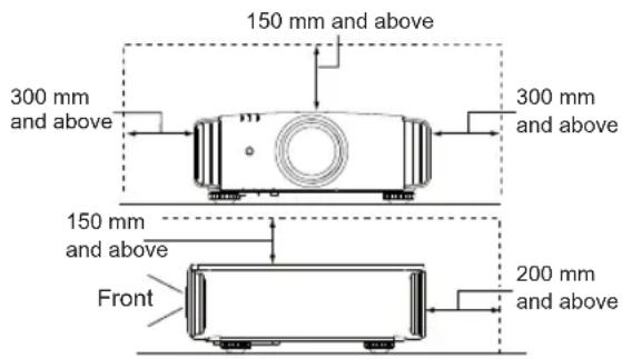
- To allow better heat dissipation, keep a clearance between this unit and its surrounding as shown below. When this unit is enclosed in a space of dimensions as shown below, use an air-conditioner so that the internal and external temperatures are the same. Overheating can cause damage.
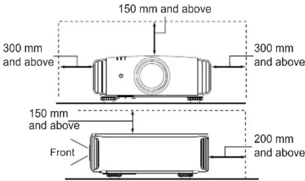
PORTABLE CART WARNING (symbol provided by RETAC)
- power source indicated on the label. If you are not sure of the type of power supply to your home, consult your product dealer or local power company.
- This product is equipped with a three-wire plug. This plug will fit only into a grounded power outlet. If you are unable to insert the plug into the outlet, contact your electrician to install the proper outlet. Do not defeat the safety purpose of the grounded plug.
- Power-supply cords should be routed so that they are not likely to be walked on or pinched by items placed upon or against them. Pay particular attention to cords at doors, plugs, receptacles, and the point where they exit from the product.
- For added protection of this product during a lightning storm, or when it is left unattended and unused for long periods of time, unplug it from the wall outlet and disconnect the cable system. This will prevent damage to the product due to lightning and power line surges.
- Do not overload wall outlets, extension cords, or convenience receptacles on other equipment as this can result in a risk of fire or electric shock.
- Never push objects of any kind into this product through openings as they may touch dangerous voltage points or short out parts that could result in a fire or electric shock. Never spill liquid of any kind on the product.
- Do not attempt to service this product yourself as opening or removing covers may expose you to dangerous voltages and other hazards. Refer all service to qualified service personnel.
- Unplug this product from the wall outlet and refer service to qualified service personnel under the following conditions:
a) When the power supply cord or plug is damaged.
b) If liquid has been spilled, or objects have fallen on the product.
c) If the product has been exposed to rain or water.
d) If the product does not operate normally by following the operating instructions. Adjust only those controls that are covered by the Operation Manual, as an improper adjustment of controls may result in damage and will often require extensive work by a qualified technician to restore the product to normal operation.
e) If the product has been dropped or damaged in any way.
f) When the product exhibits a distinct change in performance, this indicates a need for service.
- When replacement parts are required, be sure the service technician has used replacement parts specified by the manufacturer or with same characteristics as the original part. Unauthorized substitutions may result in fire, electric shock, or other hazards.
- Upon completion of any service or repairs to this product, ask the service technician to perform safety checks to determine that the product is in proper operating condition.
- The product should be placed more than one foot away from heat sources such as radiators, heat registers, stoves, and other products (including amplifiers) that produce heat.
- When connecting other products such as VCR's, and DVD players, you should turn off the power of this product for protection against electric shock.
- Do not place combustibles behind the cooling fan. For example, cloth, paper, matches, aerosol cans or gas lighters that present special hazards when over heated.
- Do not look into the projection lens while the illumination lamp is turned on. Exposure of your eyes to the strong light can result in impaired eyesight.
- Do not look into the inside of this unit through vents (ventilation holes), etc. Do not look at the illumination lamp directly by opening the cabinet while the illumination lamp is turned on. The illumination lamp also contains ultraviolet rays and the light is so powerful that your eyesight can be impaired.
- Do not drop, hit, or damage the light-source lamp (lamp unit) in any way. It may cause the light-source lamp to break and lead to injuries. Do not use a damaged light source lamp. If the light-source lamp is broken, ask your dealer to repair it. Fragments from a broken light-source lamp may cause injuries.
- The light-source lamp used in this projector is a high pressure mercury lamp. Be careful when disposing of the light-source lamp. If anything is unclear, please consult your dealer.
- Do not ceiling-mount the projector to a place which tends to vibrate; otherwise, the attaching fixture of the projector could be broken by the vibration, possibly causing it to fall or overturn, which could lead to personal injury.
- Use only the accessory cord designed for this product to prevent shock.
- For health reasons, please take a break of about 5-15 minutes every 30-60 minutes and let your eyes rest. Please refrain from watching any 3D-images when you feel tired, unwell or if you feel any other discomfort. Moreover, in case you see a double image, please adjust the equipment and software for proper display. Please stop using the unit if the double image is still visible after adjustment.
- Once every three years, please perform an internal test. This unit is provided with replacement parts needed to maintain its function (such as cooling fans). Estimated replacement time of parts can vary greatly depending on frequency of use and the respective environment. For replacement, please consult your dealer, or the nearest authorized JVC service center.
- When fixing the unit to the ceiling, Please note that we do not take any responsibility, even during the warranty period, if the product is damaged due to use of metal fixtures used for fixation to the ceiling other than our own or if the installation
environment of said metal fixtures is not appropriate. If the unit is suspended from the ceiling during use, please be careful in regard to the ambient temperature of the unit. If you use a central heating, the temperature close to the ceiling will be higher than normally expected.
- Video images can burn into the electronic component parts. Please do not display screens with still images of high brightness or high contrast, such as found in video games and computer programs. Over a long period of time it might stick to the picture element. There is no problem with the playback of moving images, e.g. normal video footage.
- Not using the unit for a long time can lead to malfunction. Please power it on and let it run occasionally. Please avoid using the unit in a room where cigarettes are smoked. It is impossible to clean optical component parts if they are contaminated by nicotine or tar. This might lead to performance degradation.
- Please watch from a distance three times the height of the projected image size. Persons with photosensitivity, any kind of heart disease, or weak health should not use 3D glasses.
- Watching 3D-images might be cause of illness. If you feel any change in your physical condition, please stop watching immediately and consult a physician if necessary.
- When watching 3D images, it is recommended to take regular breaks. As the length and frequency of the required breaks differ for every person, please judge according to your own condition.
- If your child watches while wearing 3D glasses, it should be accompanied by its parents or an adult guardian. The adult guardian should be careful to avoid situations where the child's eyes might become tired, as responses to tiredness and discomfort, etc., are hard to detect, and it is possible for the physical condition to deteriorate very quickly. As the visual sense is not yet fully developed in children under the age of 6, please consult a physician in regard to any problem concerning 3D-images if necessary.
- Note that when using the 3D feature, the video output may appear different from the original video image due to image conversion on the device.
\*DO NOT allow any unqualified person to install the unit.
Be sure to ask your dealer to install the unit (e.g. attaching it to the ceiling) since special technical knowledge and skills are required for installation. If installation is performed by an unqualified person, it may cause personal injury or electrical shock.
Safety Precautions (Continued)
POWER CONNECTION
For USA and Canada only
Use only the following power cord.
Power cord
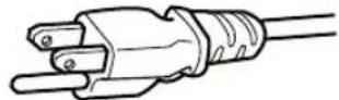
The power supply voltage rating of this product is AC110V – AC240V. Use only the power cord designated by our dealer to ensure Safety and EMC. Ensure that the power cable used for the projector is the correct type for the AC outlet in your country. Consult your product dealer.
Power cord
natural_image
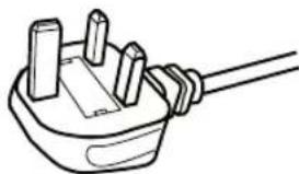
Line drawing of a plug with three pins and a wire (no text or symbols)For United Kingdom

natural_image
Line drawing of a plug with a screw and handle (no text or symbols)For European continent countries
WARNING:
Do not cut off the main plug from this equipment.
If the plug fitted is not suitable for the power points in your home or the cable is too short to reach a power point, then obtain an appropriate safety approved extension lead or adapter or consult your dealer. If nonetheless the mains plug is cut off, dispose of the plug immediately, to avoid a possible shock hazard by inadvertent connection to the main supply. If a new main plug has to be fitted, then follow the instruction given below.
WARNING:
THIS APPARATUS MUST BE EARTHED.
IMPORTANT (Europe only):
The wires in the mains lead on this product are colored Vert et jaune in accordance with the following cord:
Green-and-yellow :Earth
Blue :Neutral
Brown :Live
As these colors may not correspond with the colored making identifying the terminals in your plug, proceed as follows:
The wire which is colored green-and-yellow must be connected to the terminal which is marked M with the letter E or the safety earth or colored green or green-and-yellow. The wire which is colored blue must be connected to the terminal which is marked with the letter N or colored black. The wire which is colored brown must be connected to the terminal which is marked with the letter L or colored red.
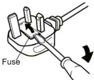
POWER CONNECTION (United Kingdom only)
HOW TO REPLACE THE FUSE:
When replacing the fuse, be sure to use only a correctly rated approved type, re-fit the fuse cover.
IF IN DOUBT — CONSULT A COMPETENT ELECTRICIAN.
Open the fuse compartment with the blade screwdriver, and replace the fuse.
(* An example is shown in the illustration below.)
Dear Customer,
This apparatus is in conformance with the valid European directives and standards regarding electromagnetic compatibility and electrical safety.
European representative of Victor Company of Japan, Limited is:
JVC Technical Services Europe GmbH
Postfach 10 05 04
61145 Friedberg
Germany
ENGLISH
Information for Users on Disposal of Old Equipment and Batteries


Products

Battery
[European Union only]
These symbols indicate that equipment with these symbols should not be disposed of as general household waste. If you want to dispose of the product or battery, please consider the collection systems or facilities for appropriate recycling.
Notice: The sign Pb below the symbol for batteries indicates that this battery contains lead.
DEUTSCH
Established by film producer George Lucas, THX aims to enhance the reproduction of audio sound and video images intended by filmmakers by setting quality standards for cinema viewing environments as well as home entertainment systems.
Based on the know-how that we have cultivated over the past 25 years in areas including film production, cinema viewing environment design, and audio/video editing, we have established a partnership with JVC to develop an unprecedented home theater projector system.
The emphases of THX Certification lie in the video quality and signal processing capability of projector products. JVC projectors, DLA-RS50 and DLA-RS60, are equipped with the THX mode, which is able to bring out the full potential of the projector when playing movies on a large screen.
Also, JVC front projectors are the first in the world (*1) to have gained the "THX 3D Display Certification" (*2) by THX Ltd.
In addition, the certification standards were established with the aim to “faithfully reproduce images at home according to the intentions of the film director” during playback of 2D or 3D images, and they are “a proof of high definition and high image quality”, indicating that a certified product has cleared more than 400 rigorous image quality tests including accuracy of color reproduction, cross-talk, viewing angles, and video processing performance.

CAUTION
In order for you to enjoy 3D movies:
- Please get ready "3D glasses" and a "3D Sync Emitter" (both sold separately).
- Please read through “Safety Precautions” (Reference page: 4), and the precautions in “Explanatory Notes on the 3D System” in “Operation Guide (Glossary)” (Reference page: 57).
*1: "First" here refers to the first among front projectors as at November 1, 2010 based on research by JVC.
*2: The recommended screen size is 90" (16:9), and this is limited to front projection only.
THX®3D
DISPLAY
RECOMMENDED USE
All Home Theaters or Living Rooms
THX CERTIFICATION FEATURES
THX Movie Mode:
■ Correct Gamma and Color Temperature
■ No Overscan or Scaling
■ Correct High Def Color Gamut
THX PERFORMANCE
Best in Class Parameters include:
■ ANSI and Sequential Contrast
■ Luminance and Color Uniformity
■ Color Tracking with Gray Scale
■ Optimum Brightness
■ Deinterlacing Performance
■ Jaggies and Contouring
Visit www.thx.com for further technical details.

For detail information about ISF, please refer web site http://www.imagingscience.com/
Contents
Getting started
Safety Precautions ......2
THX Certification RS50 RS60 ....10
Contents 12
Accessories/Optional
Accessories ......13
Check the Accessories 13
Optional Accessories 13
Controls and features ......14
Main body - Front 14
Main body - Bottom 14
Main body - Rear 15
Main body - About the indicator display .....16
Main body - Warning display and confirmation/response ....17
Main body - Input terminal 18
How to insert batteries into the remote control ....19
Preparation
About installation 20
Important points concerning the installation ....20
Installing the Projector and Screen .....21
Set Angle 21
Shift 21
Fixation of the projector 22
Screen Size and Projection Distance .....23
Effective Range of Remote Control Unit....23
About the connection .....24
Types of possible input signals (PC compatible)....24
Connection to the unit 25
Connection of the power cord (provided) ..31
Operation
Basic Operation ....32
Basic operation procedures ....32
Frequently used useful functions .....34
Setting the Screen Size ....34
Masking the Surrounding Area of
an Image 35
Temporary turning-off of the video .....36
Adjustment of the keystone correction ... 36
Adjustments and settings
in the menu 37
Structure of the menu hierarchy (summary) ....37
Menu operation button 43
Menu operation procedure ....44
Menu item description 45
Operation guide (glossary) .....56
Maintenance
Replacing the Lamp 60
Lamp replacement procedure ....60
Resetting lamp Time 62
Method for cleaning and
replacing filters 64
Others
Troubleshooting 66
In case this message is
displayed 68
RS-232C Interface 69
RS-232C Specifications 69
TCP/IP-connection 69
Command Format ....70
RS-232C Communication Examples ..... 72
Copyright and Caution .....73
About Trademarks and Copyright .....73
Caution 73
Specifications ....74
Dimensions 76
Index 77

CAUTION
About the marks used in this book
RS40 Compatible only with DLA-RS40
RS50 Compatible only with DLA-RS50
RS60 Compatible only with DLA-RS60
Accessories/Optional Accessories
Check the Accessories
Remote Control ....1 piece
AAA size Batteries (for operation confirm)....2 pieces
Power Cord For the US market (2 m) ....1 piece
Power Cord For the EU market (2 m) ....1 piece
Power Cord For the UK market (2 m) ....1 piece
Instruction manual, warranty card and other printed material are also included.
Optional Accessories
Please check with your authorized dealer for details.
Replacement Lamp: PK-L2210U
Replacement Filter: PC010661199
3D-Glasses: PK-AG1-B
3D Synchro Emitter: PK-EM1
Controls and features
Main body - Front
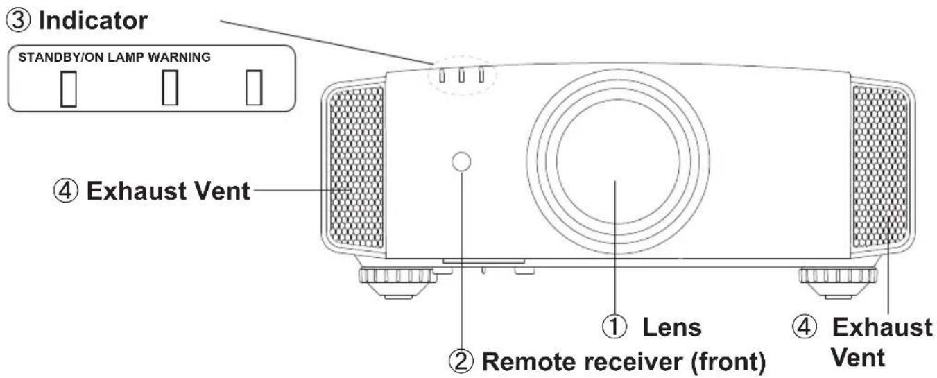
① Lens
This is a projection lens. Please do not look inside during projection.
② Remote receiver (front)
Please aim the remote control at this area when using it.
* There is also a remote receiver at the rear.
③ Indicator
Please see "About the indicator display" for details. (Reference page: 16)
④ Exhaust Vent
Warm air flows out in order to cool the interior of the set. Please do not block the vents.
Main body - Bottom
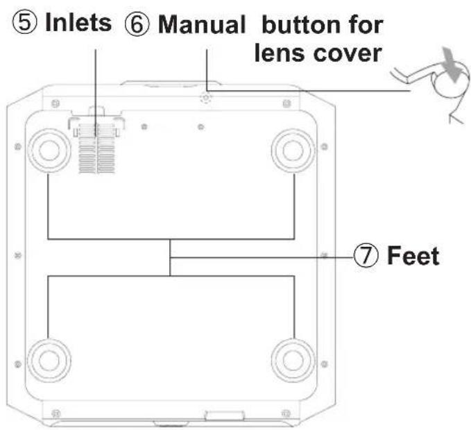
⑤ Inlets (at 3 points on the rear/bottom)
In order to cool the inside of the unit, air is let inside. Do not block or prevent the outflow of hot air. Doing so could lead to failure of the unit.
* There are inlets at two points on the right and left sides of the rear side. (Reference page: 15)
⑥ Manual operation button of the lens cover
The lens cover can be opened when pressed down. It is used for maintenance and not used during normal use.
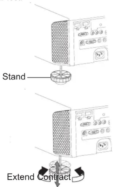
⑦ Feet
The height (0 to 5 mm) can be adjusted by turning the foot.
Controls and features (continued)
Main body - Rear

⑧ Input terminal
There is also a terminal other than the input terminal for video images, such as those used for controlling or optional equipment. This illustration is RS50 RS60. Please see "About input terminals" for detailed information RS40 about terminals. (Reference page: 18)
⑨ Lamp Cover
When replacing the light source lamp, remove this cover. (Reference page: 60)
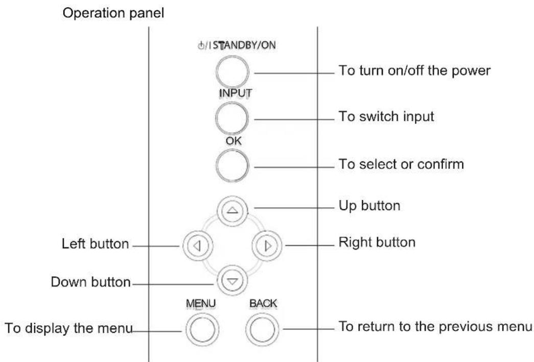
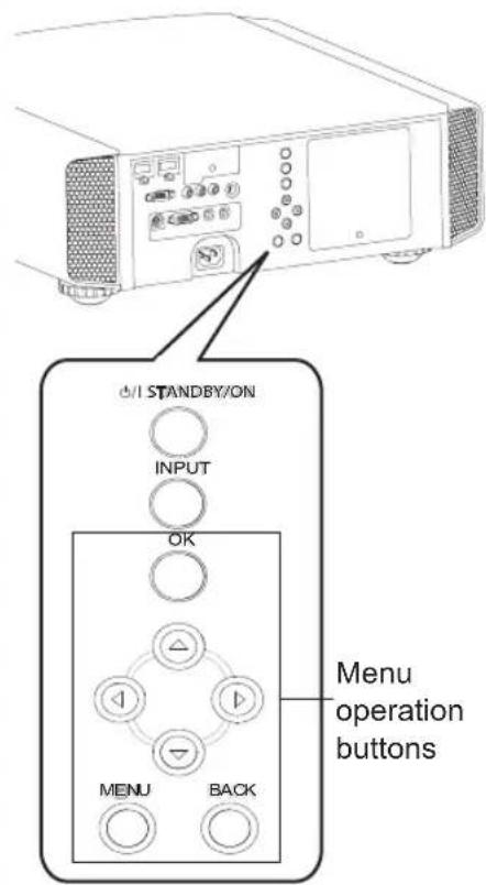
⑩ Operation panel
See the following illustration "Control panel" for more details.
⑪ Light receiving section of the remote control (rear)
Please aim the remote control at this section when using.
* There is also a light receiving section at the rear.
⑫ Power input terminal
This is the power input terminal. It is connected via the supplied power cord. (Reference page: 31)
Controls and features (continued)
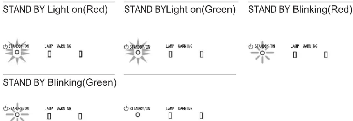
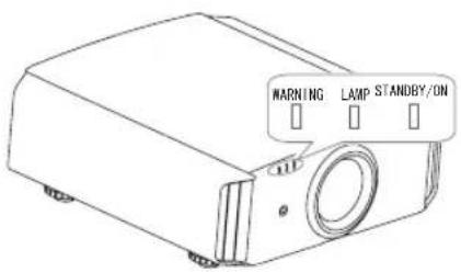
Main body - About the indicator display
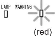
Warnings and indications used during normal operation mode of this unit are displayed with the indicators for [STAND BY / ON], [LAMP], [WARNING] at the front of this unit.
Meaning of the lighting figures:

The display the indicator lights.

They display flashing of the indicator.
Operation mode display
Displays the color and lighting/flashing of the [STAND BY / ON] indicator.
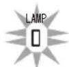
Criterion indication of the lamp replacement
Displays lighting/flashing of the [LAMP] indicator. Moreover, the [STAND BY / ON] indicator, which shows the operation mode of this unit, is displayed as described above. (Reference page: 74)
LAMP Light on(orange)
Lamp replacement is near(When accumulated lamp time has exceeded 2900 hours)


Controls and features (continued)
Main body - Warning display and confirmation/response
Warning display
You are informed of the contents of warning notices by the (repeated) displays of the [WARNING] and [LAMP] indicators. Moreover, the [STAND BY / ON] indicator, which shows the operating mode of the unit, is displayed simultaneously as described above.
Upon activation of the warning mode, the projection is interrupted at the same time for about 60 seconds and the cooling fan is turned on. Please disconnect the power plug from the electric socket after the cooling fan has stopped. Subsequently, please perform the following checks and take appropriate countermeasures.
| Lighting/flushing lights status diagram | Blinking Frequency | Content | Confirmation and countermeasures |
  Mode display Mode display | 1 time | Abnormalities in the power supply | Check that nothing is blocking the air inlets.Check that the external temperature is normal.ActionLeave the unit until it cools down.After that, turn on the power again. |
| 2 times Cooling fan stops | |||
| 3 times | Internal temperature is too high | ||
| 4 times | External temperature is too high | ||
  (orange) (red)Mode Simultaneous display flashing (orange) (red)Mode Simultaneous display flashing | 1 time | Abnormal electrical circuit | |
| 2 times | |||
| 3 times | |||
| 4 times | If something is wrong with the automatic lens cover | Check that an impact shock has not occurred during operation.Check that the lamp unit and lamp cover are correctly installed.Check that nothing is blocking the auto lens cover.ActionTurn on the power again. | |
  Mode (orange) (red) display Mode (orange) (red) display | 1 time | Lamp does not light up and unit is unable to project | |
| 2 times | Lamp is turned off during projection | ||
| 3 times | Lamp cover is removed |
If the warning indication is displayed again, please wait for the cooling fan stopped, then pull out the power plug from the power outlet. Then call your authorized dealer for repair.
(*)If the scheduled time for the replacement of the lamp is exceeded, the light might light up.
Controls and features (continued)
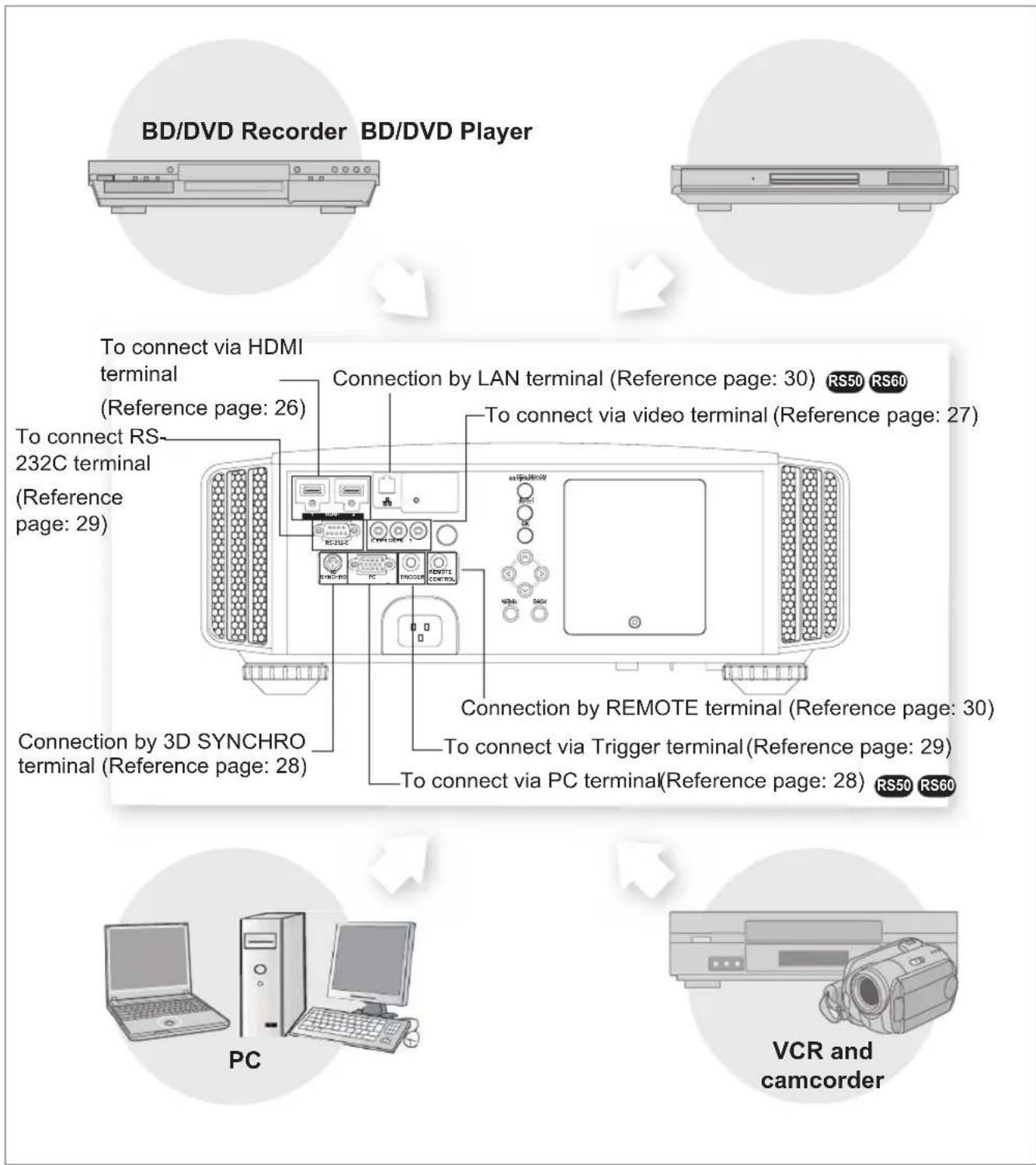
Main body - Input terminal
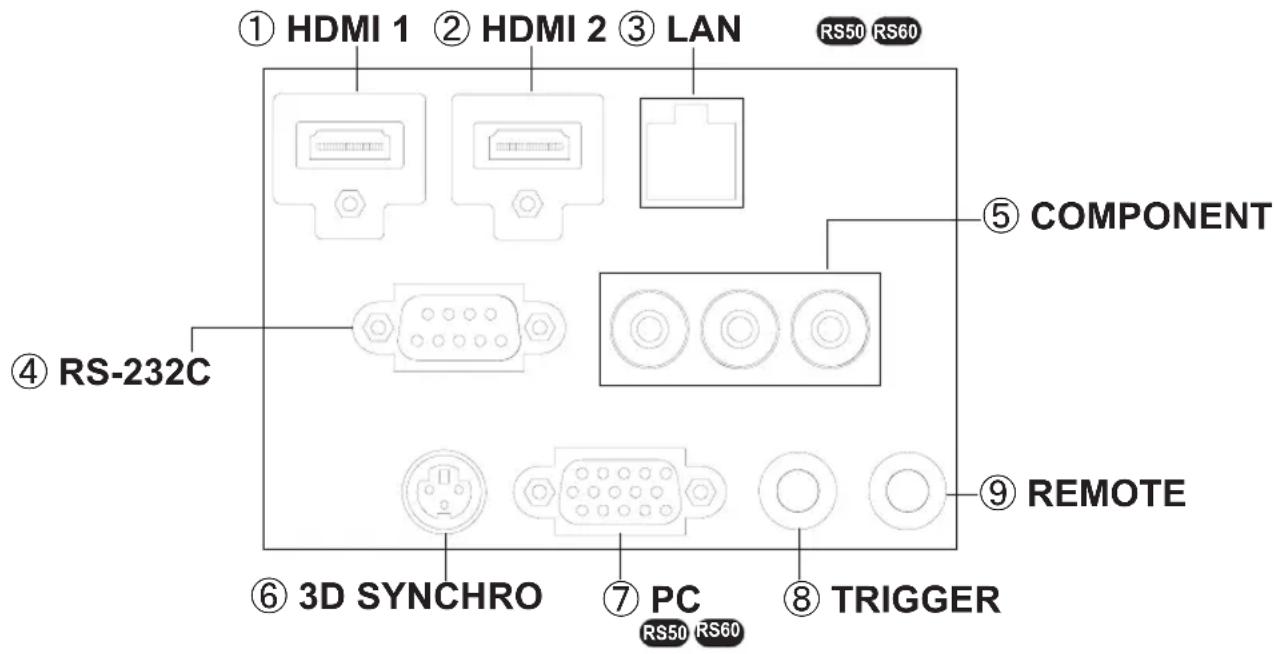
① HDMI 1 Terminal
You can connect a device equipped with HDMI output, etc. It is fitted to the M3 lock hole. Screw hole depth 3mm. (Reference page: 26)
② HDMI 2 Terminal
You can connect a device equipped with HDMI output, etc. It is fitted to the M3 lock hole. Screw hole depth 3mm. (Reference page: 26)
③ LAN terminal“RJ-45” RS50 RS60
This is a LAN-terminal. If one connects an external PC, it is possible to control this unit by sending control commands. (Reference page: 30)
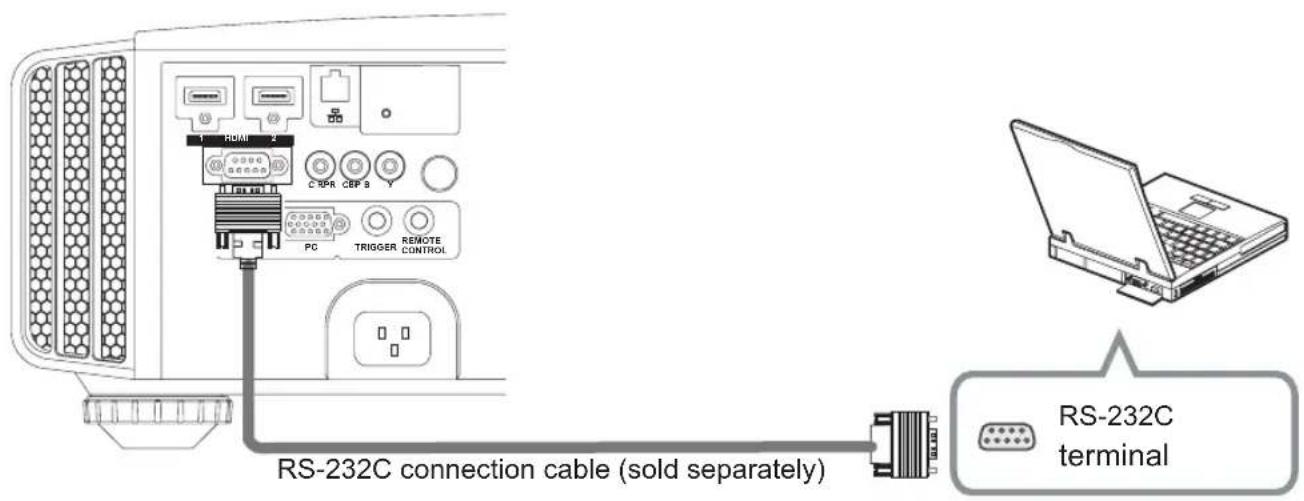
④ RS-232C terminal (male D-Sub 9 pin)
This is a RS-232C interface standard terminal. If one connects an external PC, it is possible to control this unit. (Reference page: 29)
⑤ COMPONENT terminal“RCAx3”
It is also used as input terminal for analog RGB (G on Sync) signals, component (Y, Cb, Cr) signals, DTV format (Y, Pb, Pr) signals. It can also be connected with devices, which are equipped with signal output, etc. (Reference page: 27)
⑥ 3D SYNCHRO terminal
3D synchro emitter: it is connected to the PK-EM1 (sold separately) when enjoying 3D video contents. (Reference page: 28)
⑦ PC terminal“D-Sub 15 pin” RS50 RS60
This is an input term used for Personal Computer (PC) signals only (RGB video signals and sync signals). Use to connect a computer display output terminal, etc. (Reference page: 28)
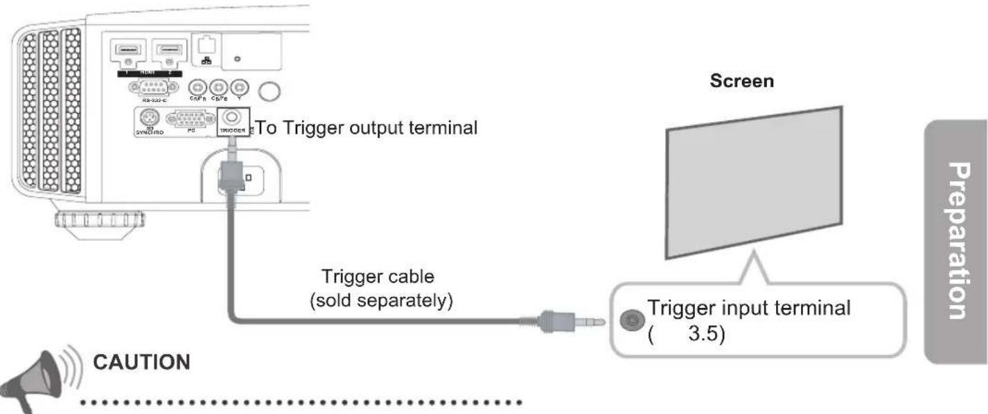
⑧ TRIGGER terminal(⊖-⊖-⊕)
DC power supply output terminal with DC12V, 100mA. It is used for output signals which control the vacillating screen responding to the SCREEN TRIGGER. Please note it can cause damage to your equipment if the connection is done incorrectly. (Tip = DC +12 V, Sleeve = GND) (Reference Page: 29, 54)
⑨ REMOTE terminal to "Stereo mini jack"
In case it is impossible to use the remote control due to the installation of this unit's dedicated BOX or rear projection, one can set up an external light receiving section. It is used to connect this external receiver and this unit. There is no such product as an external light receptor. Therefore, please consult your authorized JVC service center. (Reference page: 30)
Controls and features (continued)
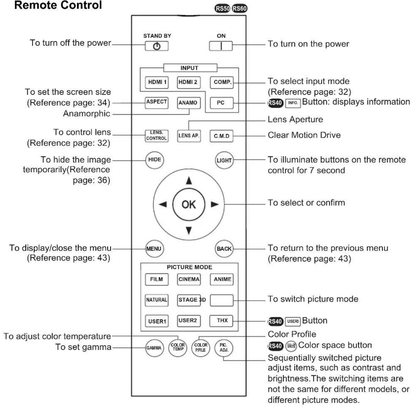
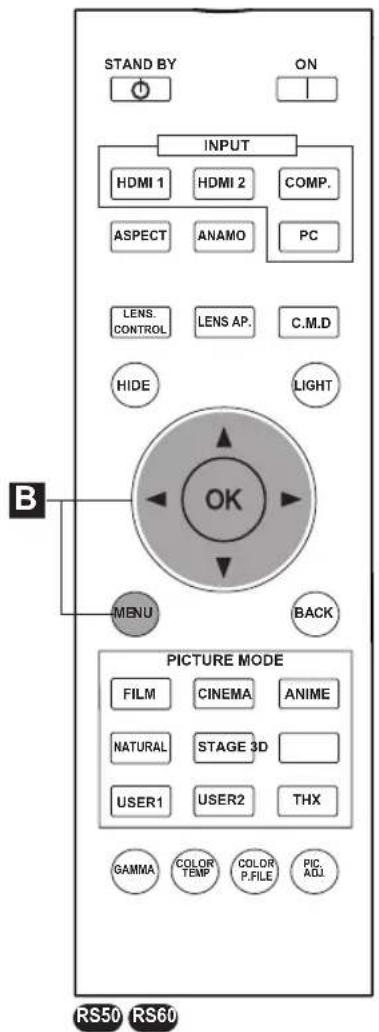
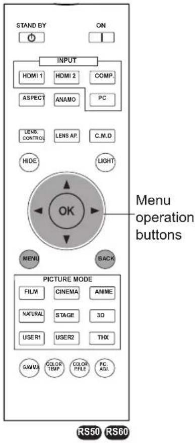
Remote Control
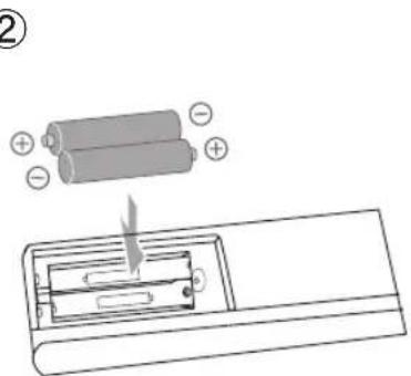
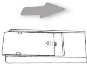
How to insert batteries into the remote control
natural_image
Diagram of a door with a speaker inside, showing an arrow pointing to the top portion (no text or symbols)②
③
natural_image
Simple line drawing of a door with an arrow pointing upward (no text or symbols)If the remote control has to be brought closer to the projector to operate, it means that the batteries are wearing out.
When this happens, replace the batteries. Insert the batteries according to the ⭕ marks.
Be sure to insert the Ⓗ end first.
If an error occurs when using the remote control, remove the batteries and wait for 5 minutes. Load the batteries again and operate the remote control.
About installation
Important points concerning the installation
Please read the following carefully before the installation of this unit.

CAUTION
Installation environment
This unit is a precision device. Therefore, please refrain from installation or use in the following locations.
Otherwise, it may cause fire or malfunction.
• Dust, wet and humid locations.
- Sooty or cigarette smoke filled locations.
- On top of a carpet or bedding, or other soft surfaces.
- Locations with high temperatures - as located in direct sunlight.
- Locations with high or low temperatures.
Permissible operating temperature range: +5° to +35°.
Relative humidity range permissible for operating: 20% \~ 80% (non-condensing).
Storage temperature tolerance: -10^ to +60^ .
- If the installation of the unit is done in a room with soot and/or smoke over a longer period, even small amounts of these substances will affect the device. This unit cools its optical components, which produce a great amount of heat, by sucking in air. If the optical circuits get dirty, this might lead to malfunctions, like the video images becoming darker or a deterioration of the color development. Dirt sticking to the optical components cannot be removed.

CAUTION
Please be careful to perform the installation at a certain distance from walls and other devices
For better heat dissipation, please keep a minimum distance between this unit and its surroundings as shown in the following illustration.
Moreover, please open the front of the unit. If there are any objects in front of the exhaust port, the hot air will flow back to the unit and heat it. The hot air flowing out of the unit might cause shadows on the screen (heat haze phenomenon).
Moreover, when it is enclosed in a space as shown in the following illustration, please make sure that the enclosed interior has the same temperature as the outside. High temperatures might lead to failure of the unit.

CAUTION
Please be careful when using
This unit uses a projection lamp, which will get hot when in use. Please refrain from projecting in the following circumstances.
Otherwise, it might cause fire or malfunction.
• Projection while lying on its side.
Please avoid projection if the installation of the unit is done at an excessive angle of more than 30. It may cause harm to the life of the lamp and color shading.
- Please avoid projection at a location where the air vents or exhaust ports might get blocked.
Please choose a non-uniform cloth material for the screen. If you choose something uniform, like something with a checkered pattern, there might be interference with the pixel array of the D-ILA components. One way to reduce the interference pattern is to change the size of the screen, so that it will not be so noticeable.
Inclination adjustment for this unit
How to adjust the vertical angle
Height and inclination of the unit (0 \~ 5mm) can be adjusted by rotating its feet. Lift the unit and adjust the four feet.
About installation (Continued)
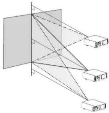
Installing the Projector and Screen
While installing, please place this unit and the screen perpendicular to each other. Failing to do so may increase trapezoidal distortion. (Reference page: 36, 52)
Set Angle
The angle range which can be set for this unit is ±30^ .
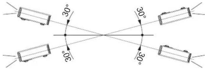
Malfunctions may occur if the angle is not set within the above-mentioned range.
Shift
Left/Right position
* 0% up/down position (center)
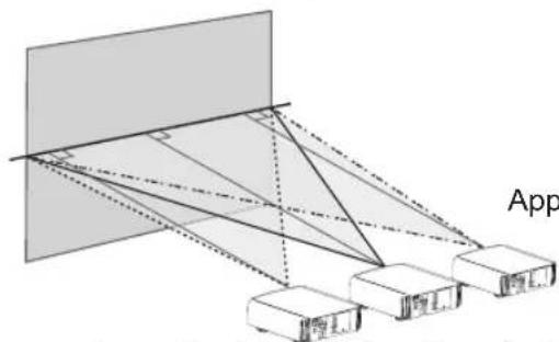
Approximately 34% (maximum) of the projected image
Approximately 34% (maximum) of the projected image
Up/Down position
* 0% left/right position (center)
natural_image
Diagram of optical or signal processing setup with lenses and detectors (no text or labels)Approximately 80% (maximum) of the projected image
Approximately 80% (maximum) of the projected image
Lens shift correlation chart:
| Left-Right Shift(%) | 0% 10% 20% | 30% 34% | |
| Up-Down Shift(%) | 80% 66% 47% | 18% 0% |
Maximum Up-Down shift varies with the amount of Left-Right shift. Likewise, maximum Left-Right shift varies with the amount of Up-Down shift.
The values on the chart are intended to act as a guide. Use them for reference during installation.
Lens shift movement range
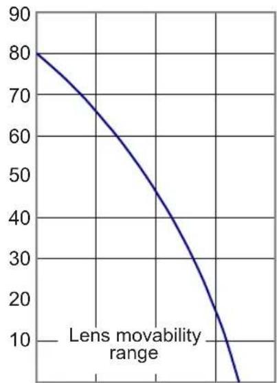
line
| Lens movability range | Value | | --------------------- | ----- | | 0 | 80 | | 10 | 60 | | 20 | 40 | | 30 | 20 | | 40 | 10 | | 50 | 5 |Horizontal lens shift
About installation (Continued)
Fixation of the projector
Measures to prevent the unit from toppling or dropping should be taken for safety reasons and accident prevention during emergencies including earthquakes.
When mounting this unit on a pedestal or ceiling, remove the 4 feet on the bottom surface and use all the 4 screw holes (M5 screws) to mount.

Precautions for Mounting
Special expertise and techniques are required for mounting this unit. Be sure to ask your dealer or a specialist to perform mounting.
Depth of the screw holes (screw length) is 23 mm. Use screws shorter than 23 mm but longer than 13 mm.
Using other screws will result in malfunctioning or cause the unit to drop.
When mounting to a pedestal, ensure sufficient space (foot height of 10 mm or higher) around the unit so that the air inlets are not blocked.
Do not tilt this unit more than ±5 degrees from side to side when using.
Regardless whether the unit is still under guarantee, JVC is not liable for any product damage caused by mounting the unit with non-JVC ceiling fittings or when the environment is not suitable for ceiling-mount.
When using the unit hanging from a ceiling, pay attention to the surrounding temperature.
When a heater is in use, temperature around the ceiling is higher than expected.
About installation (Continued)
Screen Size and Projection Distance
Determine the distance from the lens to the screen to achieve your desired screen size.
This unit uses a 2.0x power zoom lens for projection.
Relationship Between Projection Screen Size and Projection Distance
| Projection Screen Size (Height, Width) Aspect Ratio 16:9 | Approximate Projection Distance W(Wide) to T(Tele) | Projection Screen Size (Height, Width) Aspect Ratio 16:9 | Approximate Projection Distance W(Wide) to T(Tele) |
| 60" (Approx. 0.7, 1.3m) | Approx.1.78m to Approx.3.66m | 140" (Approx.1.7, 3.1m) | Approx.4.23 m to Approx.8.60m |
| 150" (Approx.1.9, 3.3m) | Approx.4.53m to Approx.9.22m | ||
| 70" (Approx.0.9, 1.5m) | Approx.2.09m to Approx.4.28m | 160" (Approx.2.0, 3.5m) | Approx.4.84m to Approx.9.84m |
| 80" (Approx.1.0, 1.8m) | Approx.2.40m to Approx.4.89m | 170" (Approx.2.1, 3.8m) | Approx.5.14m to Approx.10.45m |
| 90" (Approx.1.1, 2.0m) | Approx.2.70m to Approx.5.51m | 180" (Approx.2.2, 4.0m) | Approx.5.45m to Approx.11.07m |
| 100" (Approx.1.2, 2.2m) | Approx.3.01m to Approx.6.13m | 190" (Approx.2.4, 4.2m) | Approx.5.75m to Approx.11.68m |
| 110" (Approx.1.4, 2.4m) | Approx.3.31m to Approx.6.75m | 200" (Approx.2.5, 4.4m) | Approx.6.06m to Approx.12.30m |
| 120" (Approx.1.5, 2.7m) | Approx.3.62m to Approx.7.36m | ||
| 130" (Approx.1.6, 2.9m) | Approx.3.92m to Approx.7.98m |
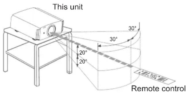
Effective Range of Remote Control Unit
When directing the remote control toward this unit.
When aiming the remote control towards the remote sensor on this unit, ensure that the distance to the sensor in front or at the rear of this unit is within 7 m.
If the remote control fails to work properly, move closer to this unit.
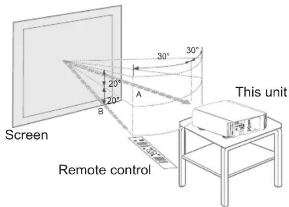
When reflecting off a screen
Ensure that the total of distance A between this unit and screen and distance B between remote control and screen is within 7 m.
As the efficiency of signals reflected from the remote control unit differ with the type of screen used, operable distance may decrease.
About the connection
Types of possible input signals (PC compatible)
HDMI
| No. | Designation | Resolution | fh [kHz] | fv [Hz] | dot CLK [MHz] | Total No. of dots [dot] | Total No. of lines [line] | No. of effective dots [dot] | No. of effective lines [line] |
| 1 | VGA 60 640 | X 480 31.500 | 60.000 | 25.200 80 | 0 525 640 | 480 | |||
| 2 | VGA 59.94 640 | X 480 31.4 | 69 59.940 | 25.175 | 800 525 640 | 480 | |||
| 3 | SVGA 60 800 | X 600 37.87 | 9 60.317 | 40.000 1 | 056 628 8 | 00 600 | |||
| 4 | XGA 60 102 | 4 X 768 48.3 | 63 60.004 | 65.000 | 1,344 806 | 1,024 | 768 | ||
| 5 | WXGA 60 12 | 80 X 768 | 47.760 60.000 | 79.99 | 8 1,675 796 | 1,280 | 768 | ||
| 6 | WXGA +60 | 1440 X 900 | 55.919 | 59.999 | 106.470 | 1,904 | 932 | 1,440 | 900 |
| 7 | SXGA 60 | 1280X 1024 | 63.981 | 60.020 | 108.000 | 1,688 | 1,066 | 1,280 | 1,024 |
| 8 | WSXGA +60 | 1680 X 1050 | 65.222 | 60.002 | 147.140 | 2,256 | 1,087 | 1,680 | 1,050 |
| 9 | WUXGA 60 | 1920 X 1200 | 74.038 | 59.95 | 154.000 | 2,080 | 1,235 | 1,920 | 1,200 |
PC (D-sub 3-lines 15 pins)
| No. | Designation | Resolution | fh [kHz] | fv [Hz] | dot CLK [MHz] | Total No. of dots [dot] | Total No. of lines [line] | No. of effective dots [dot] | No. of effective lines [line] |
| 1 | VGA60 640 | X 480 31.500 | 60.000 | 25.175 | 800 525 640 | 40 | 480 | ||
| 2 | VGA72 640 | X 480 37.900 | 72.000 | 31.500 | 832 520 640 | 40 | 480 | ||
| 3 | VGA75 640 | X 480 37.500 | 75.000 | 31.500 | 840 500 640 | 40 | 480 | ||
| 4 | VGA85 | 640 X 480 | 43.300 | 85.000 | 36.000 | 832 | 509 | 640 | 480 |
| 5 | SVGA 56 | 800 X 600 | 35.200 | 56.000 | 36.000 | 1024 | 625 | 800 | 600 |
| 6 | SVGA 60 | 800 X 600 | 37.900 | 60.000 | 40.000 | 1056 | 628 | 800 | 600 |
| 7 | SVGA 72 | 800 X 600 | 48.100 | 72.000 | 50.000 | 1040 | 666 | 800 | 600 |
| 8 | SVGA 75 | 800 X 600 | 46.900 | 75.000 | 49.500 | 1056 | 625 | 800 | 600 |
| 9 | SVGA 85 | 800 X 600 | 53.700 | 85.000 | 56.250 | 1048 | 631 | 800 | 600 |
| 10 | XGA60 | 1024 X 768 | 48.400 | 60.000 | 65.000 | 1344 | 806 | 1024 | 768 |
| 11 | XGA70 | 1024 X 768 | 56.500 | 70.000 | 75.000 | 1328 | 806 | 1024 | 768 |
| 12 | XGA75 | 1024 X 768 | 60.000 | 75.000 | 75.750 | 1312 | 800 | 1024 | 768 |
| 13 | XGA85 | 1024 X 768 | 68.700 | 85.000 | 94.500 | 1376 | 808 | 1024 | 768 |
| 14 | WXGA60 | 1280 X 768 | 47.760 | 60.000 | 79.998 | 1675 | 796 | 1280 | 768 |
| 15 | WXGA+ 60 | 1440 X 900 | 55.919 | 59.999 | 106.470 | 1904 | 932 | 1440 | 900 |
| 16 | SXGA 60 | 1280 X 1024 | 64.000 | 60.000 | 108.000 | 1688 | 1066 | 1280 | 1024 |
| 17 | SXGA+ 60 | 1400 X 1050 | 63.981 | 60.020 | 108.000 | 1688 | 1066 | 1400 | 1050 |
| 18 | WSXGA+ 60 | 1680 X 1050 | 65.222 | 60.002 | 147.140 | 2256 | 1087 | 1680 | 1050 |
| 19 | 1920x1080 60 | 1920 X 1080 | 67.500 | 60.00 | 148.500 | 2200 | 1125 | 1920 | 1080 |
| 20 | MAC13" | 640 X 480 | 35.000 | 66.667 | 30.240 | 864 | 525 | 640 | 480 |
| 21 | MAC16" | 832 X 624 | 49.107 | 75.087 | 55.000 | 1120 | 654 | 832 | 624 |
| 22 | MAC19" | 1024 X 768 | 60.241 | 74.927 | 80.000 | 1328 | 804 | 1024 | 768 |
About the connection (Continued)
Connection to the unit
Do not turn on the power until connection is complete.
The connection procedures differ according to the device used. For details, refer to the instruction manual of the device to be connected.
This device is used for image projection. Connect to an audio output device such as amplifier and speaker for audio output from the connected device.
The images may not be displayed depending on the devices and cables to be connected.
For HDMI cable (sold separately), only use one that is HDMI-approved.
It may not be possible to connect to this unit depending on the dimension of the connector cover of the cables to be connected.
About the connection (Continued)
Connecting via HDMI Cable
This unit
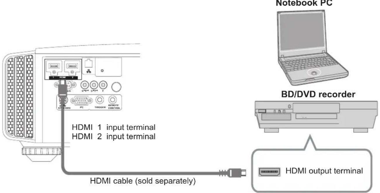
If noise is produced, take PCs (Notebook PC) away from this unit.
For a transmission bandwidth in compliance with the HDMI standard, a 340MHz cable is recommended. In case a cable is used for transmission bandwidth of 75MHz, it is recommended to choose 1080i or less for the transmitting equipment.
If the video is not displayed, try to reduce the length of the cable or lowering the resolution of the video transmitting equipment.
Connecting via HDMI-DVI Conversion Cable
This unit
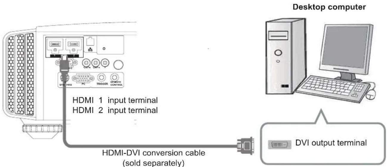
If noise is produced, take PCs (desktop computer) away from this unit.
If the video is not displayed, try to reduce the length of the cable or lowering the resolution of the video transmitting equipment.
About the connection (Continued)
Connecting via Component Video Cable
This unit
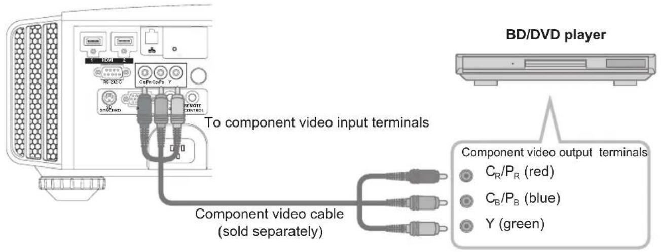
Set "COMP." in the setting menu to "Y Pb/Cb Pr/Cr". (Reference page: 52)
Connecting via RGB Video Cable
This unit
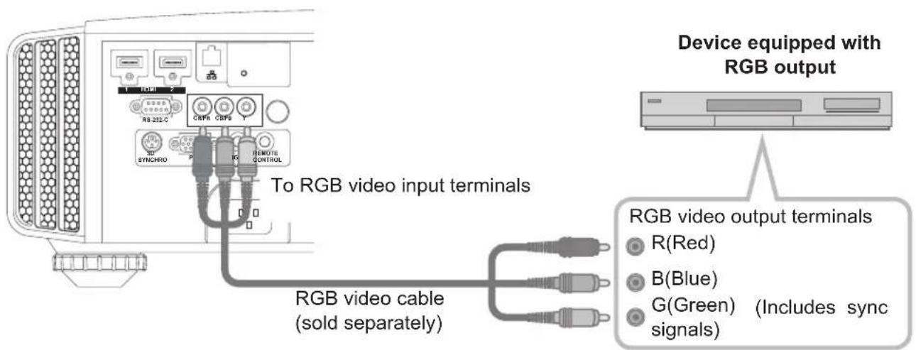
Set "COMP." in the setting menu to "RGB". (Reference page: 52)
For information on compatible input signals, see "Specifications".(Reference page: 74)
About the connection (Continued)
Connecting via PC Cable RS50 RS60
This unit
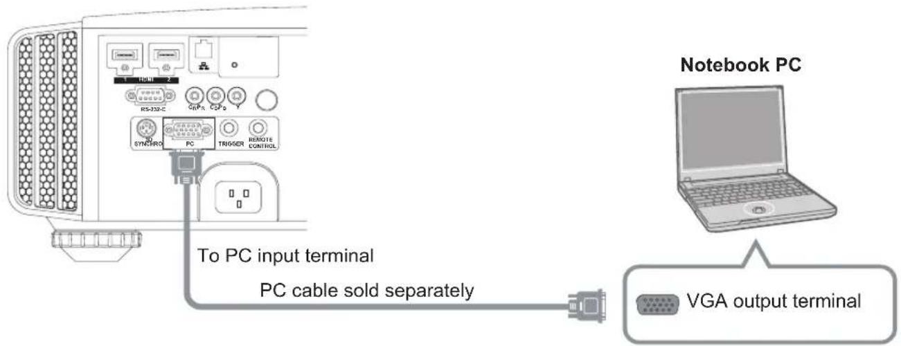
For information on supported input signals, please refer to Specifications (Reference page: 74)
Connected by a 3D SYNCHRO terminal
This unit
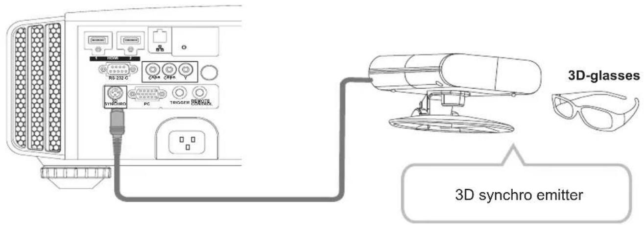
3D synchro emitter: This is a dedicated terminal for PK-EM1 (sold separately).
3D glasses (PK-AG1-B) is an optional device, and is not included in the 3D synchro emitter.

CAUTION
Note that converting 2D images to 3D ones using the 3D feature of this product, and playing them for commercial purposes or for broadcasting in public places may infringe the rights of authors protected under the copyright laws.
3D images may appear different depending on the ambient temperature and lamp usage. Stop using the projector if images cannot be projected correctly.
Before you watch 3D video images, make sure to read "3D description of the system" (Reference page 57 to 59).
About the connection (Continued)
Connecting via Trigger Cable
This unit
flowchart
graph TD
    A["Device with 3.5 timer"] --> B["Trigger input terminal (3.5)"]
    B --> C["Screen"]
    D["To Trigger output terminal"] --> E["Trigger cable (sold separately)"]
    E --> F["Preparation"]
Do not supply the power to the other devices.
Do not connect audio terminals of the other devices such as headphones etc. Otherwise, this may cause a malfunction of the other devices or injury.
Using beyond the rated value will cause malfunction.
The default is set to "No output". Please set it under the item "Trigger" of menu [5] "Function" (Reference page: 54).
Connected by RS-232C connection cable
This unit
About the connection (Continued)
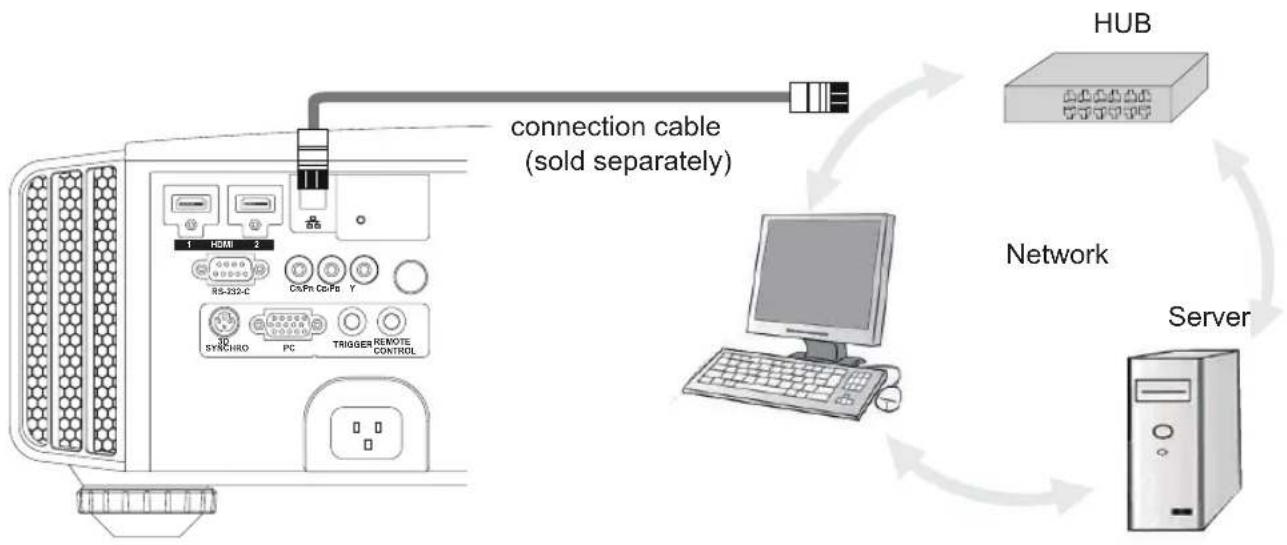
Connected by LAN terminal RS50 RS60
This unit
flowchart
graph TD
    Server["Server"] -->|Connection| HUB["HUB"]
    HUB -->|connection cable (sold separately)| RSR232C["RS-232-C"]
    RSR232C -->|1| HDMI["1 HDMI"]
    RSR232C -->|2| RS-232C
    RS-232C -->|30| SYNCHRO["30 SYNCHRO"]
    RS-232C -->|PC| TRIGGER["TRIGGER"]
    RS-232C -->|Y| CSPR["CSPR"]
    RS-232C -->|Y| CSPR
    RS-232C -->|Y| TRIGGER
    RS-232C -->|Y| TRIGGER
    RS-232C -->|Y| TRIGGER
    HUB -->|Network| HUB
    HUB --> Server
The network is used to control the unit. It is not used for transmission of the video signal.
Please contact your network administrator for questions concerning the network connection.
Connected by a REMOTE terminal
This unit
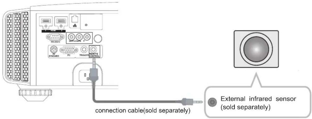
For an external infrared sensor and connecting cable, please contact your dealer or a JVC service center.
About the connection (Continued)
Connection of the power cord (provided)
Once you have connected the equipment, connect the projector power cord.
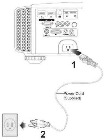
1 Connect the power cord supplied with the unit power input terminal
2 Connect to the power outlet
Be carful to avoid fire and electric shocks

the wall outlet.
damaged if you place it under heavy objects, heat or pull it.
Basic Operation
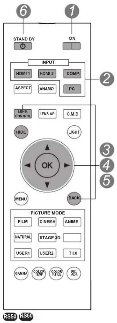
Basic operation procedures
Once you have finished the basic setup, the unit can normally be used just with the following operations.
1 Turn on power source
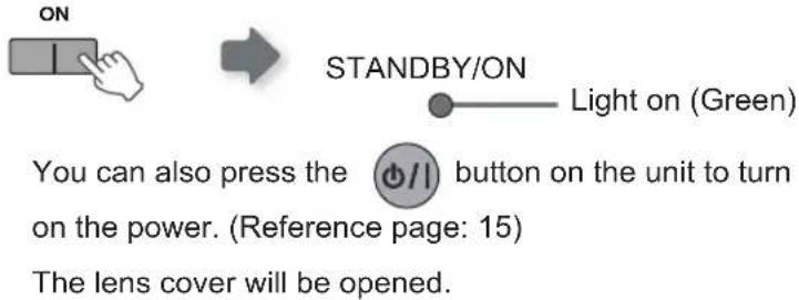
2 Choose the projected image
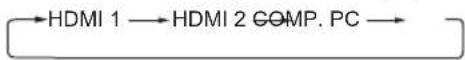
1 Select input mode
You can also select the input mode by pressing the button on the unit. (Reference page: 15)
2 Play back the selected device
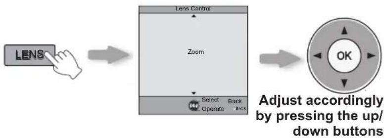
3 Adjust the zoom (screen size)
flowchart
graph LR
    A["LENS"] --> B["Zoom"]
    B --> C["Select Back"]
    B --> D["Operate Back"]
    C --> E["OK"]
    D --> E
    style A fill:#f9f,stroke:#333
    style B fill:#ccf,stroke:#333
    style C fill:#cfc,stroke:#333
    style D fill:#fcc,stroke:#333
    style E fill:#ffc,stroke:#333
4 Adjust the focus (focal point)
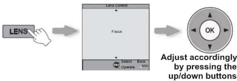
flowchart
graph LR
    A["LENS"] --> B["Focus"]
    B --> C["Select Back"]
    B --> D["Operate Back"]
    C --> E["OK"]
    D --> E
    style A fill:#f9f,stroke:#333
    style B fill:#ccf,stroke:#333
    style C fill:#cfc,stroke:#333
    style D fill:#fcc,stroke:#333
    style E fill:#ffc,stroke:#333
5 Adjust the shift (image position)
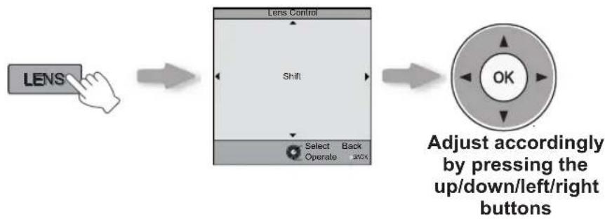
flowchart
graph LR
    A["LENS"] --> B["Lens Control"]
    B --> C["Select Back Operate switch"]
    C --> D["Adjust accordingly by pressing the up/down/left/right buttons"]
After adjusting the image position, it may be necessary to select "Pixel Adjust" from the Settings menu "Installation". (Reference page:53)
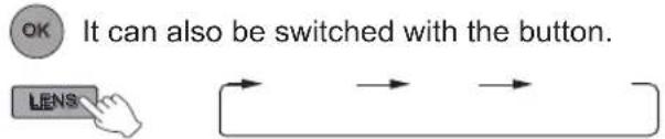
Every time the LENS button is pressed, the adjustment item will be switched among "Focus", "Zoom" and "Shift".
6 Turn off power source
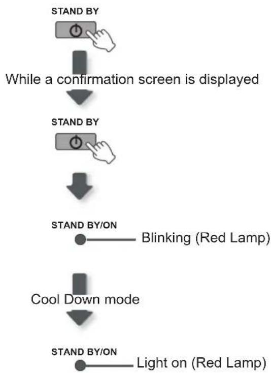
flowchart
graph TD
    A["STAND BY"] --> B["While a confirmation screen is displayed"]
    B --> C["STAND BY"]
    C --> D["STAND BY/ON"]
    D --> E["Blinking (Red Lamp)"]
    C --> F["Cool Down mode"]
    F --> G["STAND BY/ON"]
    G --> H["Light on (Red Lamp)"]
When power off, the lens cover will be closed.
The power cannot be turned off within approximately 90 seconds after it has been turned on. Start operation only after 90 seconds time.
You can also press the ⏻/1 button on the unit to turn off
the power. (Reference page: 15)
Pull out the power plug when the unit will not be used for a prolonged time.
MEMO
About Cool Down mode
The Cool Down mode is a function to cool down the lamp for approximately 60 seconds after projection is complete. This function prevents the internal parts of the unit from deformation or damage due to overheating of the lamp. It also prevents lamp blowout and premature shortening of lamp life.
During Cool Down mode, the [STANDBY/ON] indicator blinks in red.
After the Cool Down mode is complete, the unit automatically returns to standby mode.
Do not pull out the power plug during Cool Down mode. This may shorten the lamp life and cause a malfunction.
Basic Operation (continued)
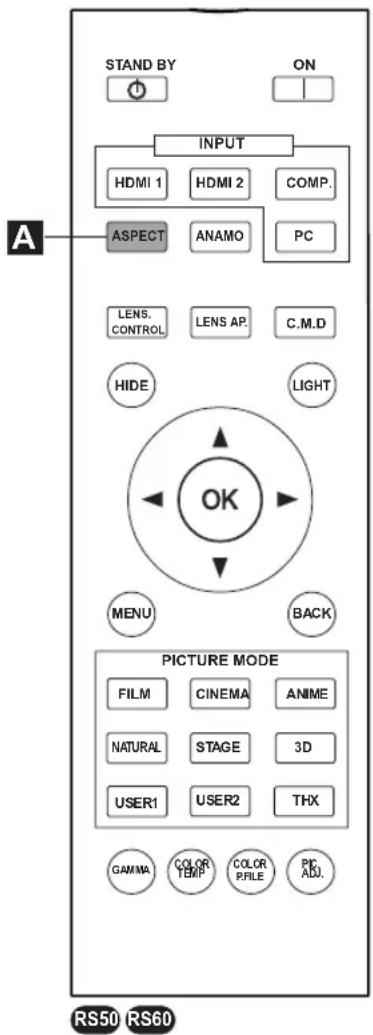
Frequently used useful functions
You can change the screen size of the projected image or hide the surrounding area of an image for which quality at the outer area has deteriorated.
A Setting the Screen Size
B Masking the Surrounding Area of an Image
c Temporary turning-off of the video
D Adjustment of the keystone correction
A Setting the Screen Size
The projected image can be set to a most appropriate screen size (aspect ratio).
flowchart
graph LR
    A["ASPECT"] --> B["4:3"]
    B --> C["16:9"]
    C --> D["Zoom"]
"Aspect(Video)" of the
setting menu. (Reference page: 50)
"Aspect(Computer)" setting will be
available instead. (Reference page: 50)
Input Image and Projected Image by Different Screen Size
| Input Image | Screen Size | ||
| 4:3 | 16:9 | Zoom | |
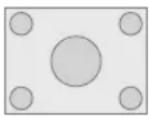 SDTV(4:3) SDTV(4:3) | 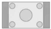 Aspect Ratio:Same Most appropriate screen size Aspect Ratio:Same Most appropriate screen size |  Aspect Ratio: Landscape Image is stretched horizontally Aspect Ratio: Landscape Image is stretched horizontally |  Aspect Ratio:Same Top and bottom of the image are missing Aspect Ratio:Same Top and bottom of the image are missing |
 SDTV(4:3)Image recorded in landscape (black bands on top and bottom) of DVD software SDTV(4:3)Image recorded in landscape (black bands on top and bottom) of DVD software |  Aspect Ratio:Same Small image is projected Aspect Ratio:Same Small image is projected |  Aspect Ratio: Landscape Image is stretched horizontally Aspect Ratio: Landscape Image is stretched horizontally |  Aspect Ratio:Same Most appropriate screen size Aspect Ratio:Same Most appropriate screen size |
“4:3” may result in a vertically stretched image, while selecting “16:9” provides you with the most appropriate screen size.
"16:9".
MEMO
Masking is available only when high definition images are input.
B Masking the Surrounding Area of an Image
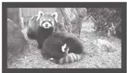
Images for which quality at the outer area has deteriorated can be projected by masking (hiding) the surrounding area of the projected image.
1 Project the image
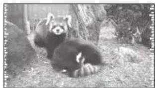
natural_image
Red panda resting on grassy ground with tree branches in background (no text or symbols visible)
Image for which quality at the outer area has deteriorated.
2 Mask the image
1 Display the setting menu


2 Select "Input Signal" → "Mask"
①
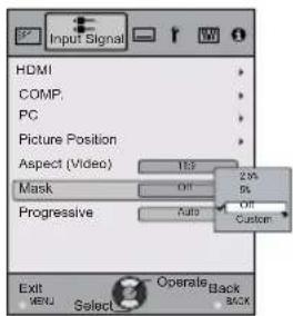
3 Set a mask value
①
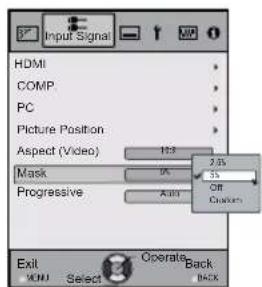
Example:
When the "Mask" value is changed from "Off" → "5%"
natural_image
Black-and-white photo of two red pandas resting on straw bedding in a natural setting (no text or symbols visible)
To end

Basic Operation (continued)
When there is a 3D input signal, adjustment is not possible. Moreover, even if the keystone correction is adjusted, keystone correction is removed when there is a 3D input signal.
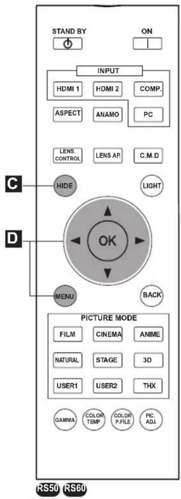
c Temporary turning-off of the video
You can hide the image temporarily.

Press the HIDE button again to display image.
The power cannot be turned off when the image is temporarily hidden.
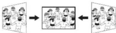
D Adjustment of the keystone correction
In regards to the projection plane, any occurring keystone distortion is adjusted in case the installation location is inclined.
1 Display the setting menu
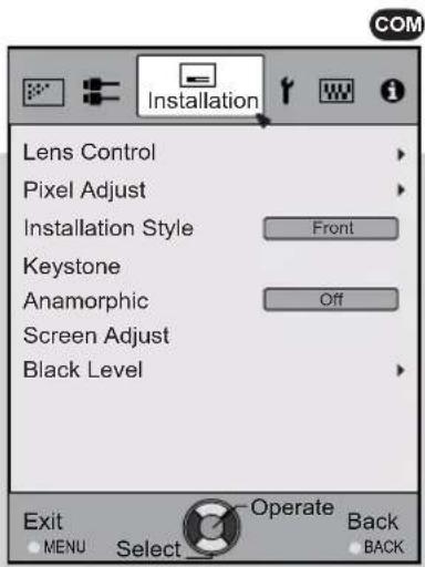
2 Select "Installation" → "Keystone"
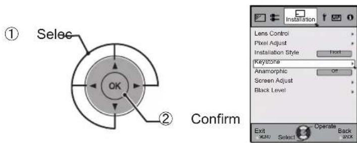
3 Adjusts keystone correction
If one presses the cursor (vertical and horizontal arrows) in the keystone correction mode, the keystone distortion can be adjusted.
Adjust horizontal distortion with the cursors for left and right.
flowchart
graph LR
    A["Top: Group of people"] --> B["Right: Group of people"]
    B --> C["Left: Group of people"]
Adjust vertical distortion with the cursors for up and down.
4 Exit

Adjustments and settings in the men
Structure of the menu hierarchy (summary)
The Menu of this unit is organized as follows. As this is only a brief guideline, items, which might not be displayed due to certain settings, are still displayed in the illustration. Moreover, in regard to COM, it shows countermeasures for all kinds of devices, but there the values for setting and adjustment might be different. See “Description of menu items” (Reference: Since 45 and following) for details. It can be moved to subscreens used for adjustment, even for items that do not feature submenus.
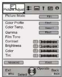
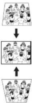
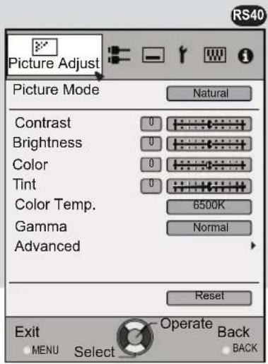
[1] Picture Adjust
(*) Apart from "Film", "Brightness/darkness correction" is displayed in the "Picture Mode".
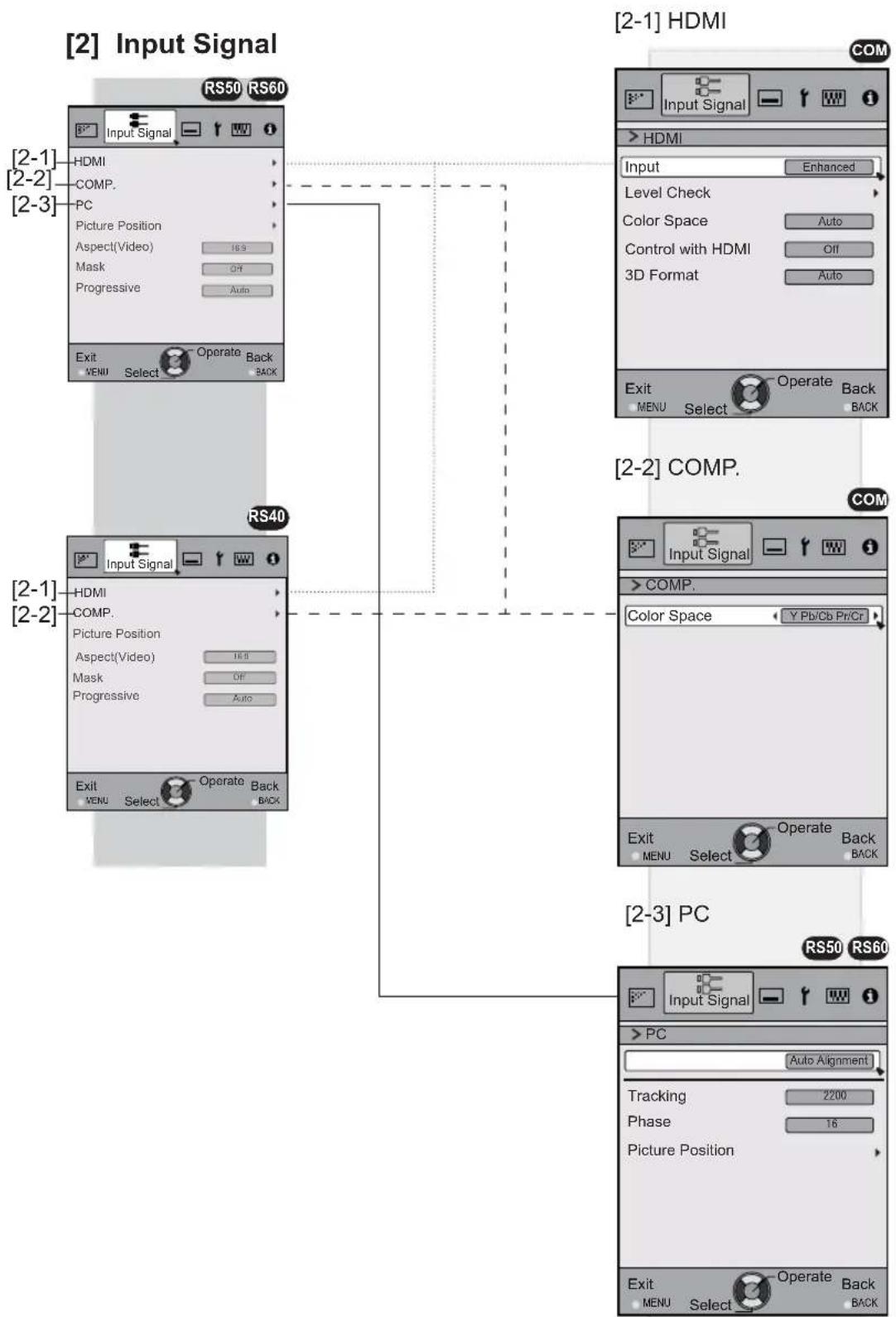
[2] Input Signal
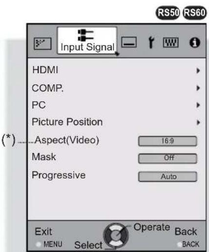
(*) When there is a PC signal input, "Aspect (PC)" is displayed.
Continue to the next

To “[1] Layers and organization of the picture quality submenu”
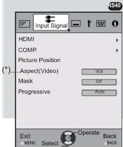
(*) When there is a PC signal input, "Aspect (PC)" is displayed.
To “[2] Layers and organization of the input signal submenu”
Adjustments and settings in the menu (continued)
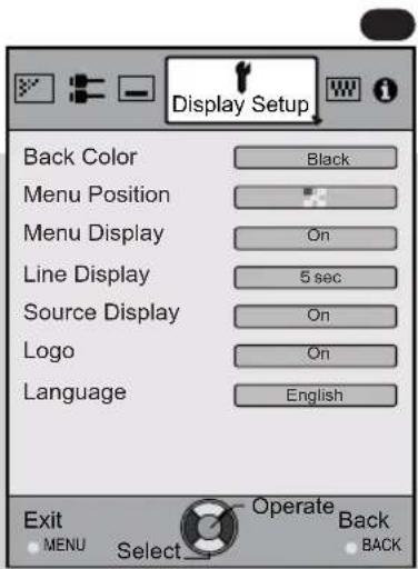
[4] Display Setup[3] Installation
Continued from the previous page
Continue to the next

To “[3] Layers and organization of the installation submenu”
Adjustments and settings in the menu (continued)
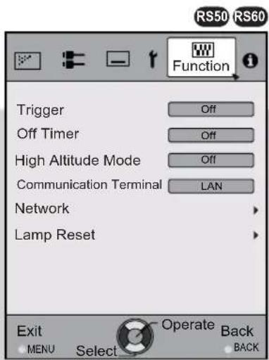
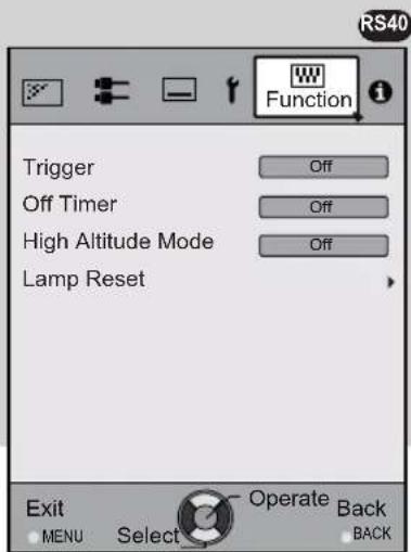
[5] Function
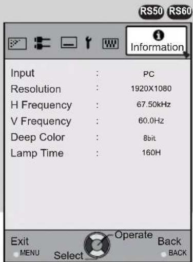
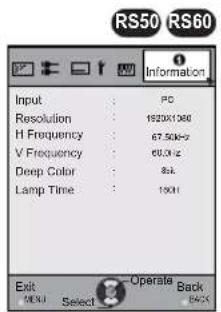
[6] Information

Continued from the previous page
For PC signal input

To “[5] Layers and organization of the function submenu”
Adjustments and settings in the menu (continued)
[1] Layers and organization of the picture adjust submenu
![JVC DLARS60U3D - [1] Layers and organization of the picture adjust submenu - 1](/content/2026/03/516020/images/6e127d08be2d9746d078b5f3a56c4628d959cfdf62bd62cb152d48280e75edfe.jpg)
flowchart
graph TD
    A["[1"] Picture Adjust] --> B["[1-1"] Color temp.]
    B --> C["[1-2-1"] Sharpness]
    C --> D["[1-2-3"] Color Management]

    subgraph["1-1"] Color Temp.
        E["RS50 RS60"] --> F["RS40"]
        F --> G["RS50 RS60"]
    end

    subgraph["1-2"] Advanced
        H["RS50 RS60"] --> I["RS40"]
        I --> J["RS50 RS60"]
    end

    subgraph["1-2-1"] Sharpness
        K["RS50 RS60"] --> L["RS40"]
        L --> M["RS50 RS60"]
    end

    subgraph["1-2-3"] Color Management
        N["RS50 RS60"] --> O["RS40"]
        O --> P["RS50 RS60"]
    end
Adjustments and settings in the menu (continued)
[2] Layers and organization of the input signal submenu
flowchart
graph TD
    A["Input Signal"] --> B["Input: HDMI"]
    B --> C["Comp: Color Space"]
    C --> D["Back: 3D Format"]
    D --> E["Output: Edit/Finish"]
    F["Input Signal"] --> G["Input: HDMI"]
    G --> H["Comp: Color Space"]
    H --> I["Back: Edit/Finish"]
    J["Input Signal"] --> K["Color: 16.3, 16.8, Off, Active Back"]
    K --> L["Output: Edit/Finish"]
    M["Input Signal"] --> N["Color: 16.8, 16.8, Off, Active Back"]
    N --> O["Output: Edit/Finish"]
    P["Input Signal"] --> Q["Color: 16.8, 16.8, Off, Active Back"]
    Q --> R["Output: Edit/Finish"]
    S["Input Signal"] --> T["Color: 16.8, 16.8, Off, Active Back"]
    T --> U["Output: Edit/Finish"]
    V["Input Signal"] --> W["Color: 16.8, 16.8, Off, Active Back"]
    W --> X["Output: Edit/Finish"]
    Y["Input Signal"] --> Z["Color: 16.8, 16.8, Off, Active Back"]
    Z --> AA["Output: Edit/Finish"]
Adjustments and settings in the menu (continued)
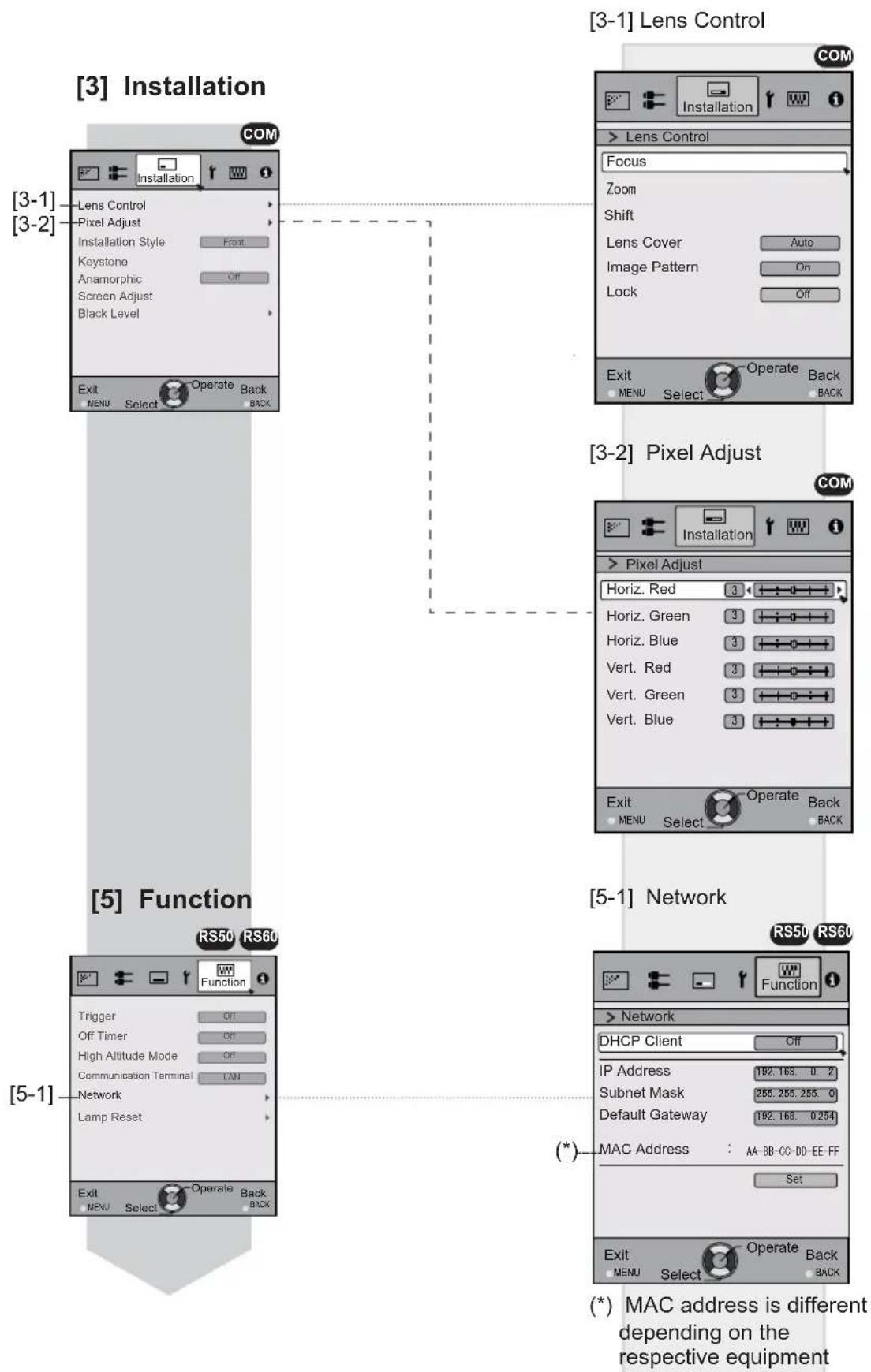
Layers and organization of the submenus [3] installation and [5] function
flowchart
graph TD
    A[" [3-1"] Lens Control ] --> B[" [3-2"] Pixel Adjust ]
    B --> C[" [5-1"] Network ]
    C --> D[" (*) MAC address is different depending on the respective equipment "]

    subgraph Installation
        E[" [3-1"] Lens Control ]
        F[" [3-2"] Pixel Adjust ]
    end

    subgraph Function
        G[" [5-1"] Network ]
        H[" (*) MAC address is different depending on the respective equipment "]
    end

    I[" [5-1"] Function ]
    J[" [3-1"] Installation]
    K[" [3-2"] Installation ]
    L[" [5-1"] Function ]
    M[" [3-1"] Lens Control ]
    N[" [3-2"] Pixel Adjust ]
    O[" [5-1"] Network ]
    P[" (*) MAC address is different depending on the respective equipment "]
Adjustments and settings in the menu (continued)
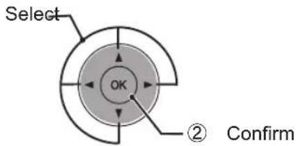
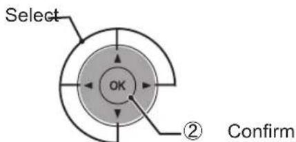
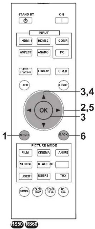
Menu operation button
Operate the menu by use of the buttons on the main body or the remote control.
| Button | Function | |
MENU  | MENU  | Menu is displayed.● While the menu is displayed, the menu screen is turned off. |
OK OK |  | While showing "Main menu" (Layer 1) selected items are confirmed, and "Submenu" (Layer 2) will be displayed. When the submenu is displayed, press OK, and the displayed items in the selection are moved to the "Setting screen" (Layer 3). |
BACK  | BACK  | Return to the previous menu screen. The menu screen is turned off when the main menu screen is shown. |
 This unit This unit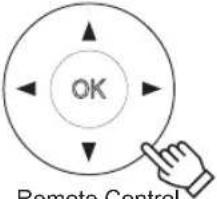 Remote Control Remote Control | Displaying the main menu and the submenu◄►: Select an adjustment item in the menu. Set the setting value of the selected adjustment item. The adjusted setting value is immediately reflected in the image.▼/▲: Selection of a displayed sub-menu item. Selection of an item in the menu. | |
Adjustments and settings in the menu (continued)
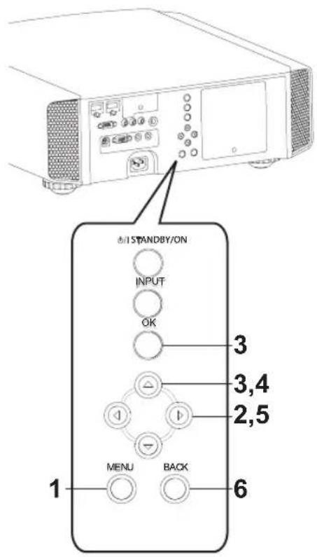
Menu operation procedure
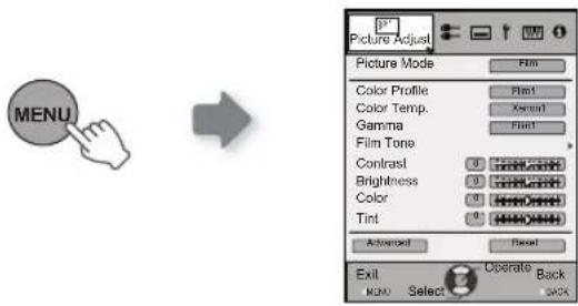
1 Press MENU.
The main menu is displayed on the screen.
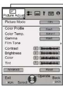
- The submenu items, which are currently selected, are shown. Currently selected menu items are highlighted and the icon is colored in orange.
—The submenu items, which are currently selected, are displayed.
Example: Picture Adjust RS50 RS60
2 Press cursor (◀/▶) to select a submenu.
setup, function, information) is selected:
selected video input and PC input are displayed at the bottom of the menu.
3 Press OK or cursor (▼)▼
picture mode. See "Content menu" on the next page for more details.

Example: Input of signals other than PC signals
Example: When inputting PC signals
4 Press the cursor (▲/▼) to select the items to adjust.
If the name of a submenu item is displayed in a dimmed manner, it cannot be selected.
5 Press cursor (◀ / ▶) to change settings.
6 After adjusting, press BACK.
Every time it is pressed, you will return to the respective previous menu screen.
7 Repeat steps 6-2 to adjust other items.
After all adjustments are done, press MENU, and the menu disappears from the screen.
Adjustments and settings in the menu (continued)
Menu item description
All numbers for the items within [ ] are default settings.
down, left, right arrows).
any signal.
[1] Picture Adjust
| Picture Mode | Please refer to the description of each mode, and then use the mode to best suited for you. Moreover, it is possible to adjust the image quality by using a user 1, 2, and 3. Settings: Film, Cinema, Animation, Natural, Stage, 3D, THX, User 1, User 2, User 3. [Natural] |
| Film | This quality setting is similar to the texture of the film setting. It is suitable for watching movies in general. |
| Cinema | This image setting is based on the DCI standard and brings to life brightly colored pictures. Suitable for viewing action movies and brightly colored images.DCI: Shorthand for Digital Cinema Initiatives. |
| Animation | An image quality setting for watching animation movies and the like. |
| Natural | It is an image quality setting with natural color/tone. Suitable for viewing video material, such as dramas/serials. |
| Stage | This image quality setting is suitable for watching of live events, e.g. on a stage. |
| 3D | This is an image quality setting for watching 3D movies. |
| User 1 | The users 1, 2, and 3 should adjust the image quality as desired in each case. Data of the last adjustment is saved. |
| User 2 | |
| User 3 RS40 | |
| THX RS50 RS60 | It is an image setting certified by the company THX. |
| Color ProfileRS50 RS60 | It selects a color profile to suit the input source. Depending on the settings, the items that can be set in the "Picture Mode" vary. (See Table 1)The color profile is selected based on the video production. We recommend to match the color profile of the video you want to watch.(*) If you select "Off", it is impossible to perform any picture adjust for other color temp. other than "Lamp power" and "Lens aperture" under "Advance", and also not gamma or sharpness.Setting: Film 1, Film 2, Cinema 1, Cinema 2, Standard, Anime 1, Anime 2, Video, Vivid, Adobe, Stage, 3D, Off.Depending on the picture mode, the default values will change. [See table 1] |
| Film 1 This is a profile that comes close to a color space that resembles using a Xenon lamp to transmit a film used for movies by the Eastman Kodak Company. | |
| Film 2 This is a profile that comes close to a color space that resembles using a Xenon lamp to transmit a film used for movies by the FUJIFILM Corporation. | |
| Cinema 1 | This is a profile that resembles the color space of the DCI standard. |
| Cinema 2 | This is a profile that resembles the color space of HDTV. |
| Standard | It is a profile with an especially rich representation of the film-specific colors.HDTV: Shorthand for High Definition Television. |
| Anime 1 | This is a profile suitable for CG-animations, which can be often found in Hollywood-produced animated series.It is intended for animations with multiple bright colors. |
| Anime 2 | This is a profile suitable for animation cel-style animation series, which are common in Japan.It is intended for animations with many dim colors. |
| Video | This profile is suitable e.g. for TV / drama / sports. |
| Vivid | This is a profile with rich sense of color, which makes it suitable for games. |
| Adobe | This is the color profile for Adobe RGB.(*) Adobe, and the Adobe logo are registered trademarks or trademarks of Adobe Systems Incorporated in the United States and/or other countries. |
| Stage | This profile is suitable for live music, orchestra and opera concerts, theater, etc. |
| 3D | This is the most suitable profile when using 3D-glasses. |
| Off | It is a mode that does not adjust the color management. |
Adjustments and settings in the menu (continued)
[Table 1] The setting contents and default values RS50 RS60 of the color profiles for the picture mode
| Picture Mode | ||||||||
| Film C | inema Anime Natural Stage 3D | THX User 1, 2 | ||||||
| Color Profile | Film 1 Cinema 1 Anime 1 | Video Stage 3D THX | Everything is displayed except for Film 1 and Film2. | |||||
| Film 2 Cinema 2 Anime 2 Vivid Standard Standard | ||||||||
| Standard Standard Adobe | Vivid | |||||||
| Standard | ||||||||
This is the default value according to the picture mode.
| Color Temp. | It is possible to set the color temp.To "[1-1] Color Temp." of the submenu |
| Gamma | It is possible to set the gamma curve. Please set to your preference.Settings: Normal, A (3D), B (3D), Film 1, Film 2, Film 3 Film 4, A, B, C, D, Custom 1,Custom 2, Custom 3 [Normal] |
| Normal | Typically we recommend this setting.(*) It is not possible to set it when the "Picture Mode" is set to "3D".(*) It is not possible to set it when the "Picture Mode" is set to "Film". RS50 RS60 |
| A (3D)B (3D) | A (3D), B (3D) can only be set, if the "Picture Mode" is "3D".This is the normal gamma curve for 3D.A (3D) will be brighter. |
| Film 1 | Film 1, 2, 3, 4 can only be set if the "Picture Mode" is set to "Film". RS50 RS60This is a gamma curve that approximates the characteristics of an Eastman Kodak Company film for movies. |
| Film 2 | This is a gamma curve that approximate the gamma curve characteristics of a cinematographic film made by the FUJIFILM Corporation. |
| Film 3 | This is a gamma curve that is even more focused on tone for the gamma of Film 1. |
| Film 4 | This is a gamma curve that emphasizes more contrast for the gamma of Film 2. |
| A | A, B, C, D cannot be set if the "Picture Mode" is "3D".(*) It is not possible to set it when the "Picture Mode" is set to "Film". RS50 RS60 |
| A | In regard to normal gamma, this is a gamma curve focused on tone. |
| B | This is a gamma curve for the film's unique S curve. |
| C | This is a gamma curve that – in regard to the gamma of B – emphasized even more the feeling of contrast. |
| D | For normal, this is a gamma curve where the intermediate gradations look very bright. |
| Custom 1 | Custom 1, 2, 3 cannot be set if the "Picture Mode" is "3D". |
| Custom 2 | Under submenu "[1-2-2] Custom Gamma", it is possible to change the gamma curve and save it. |
| Custom 3 | The initial value of Custom 1, 2, and 3 is the same as for "Normal". |
| Film ToneRS50 RS60 | You can reproduce the intensity of the exposure image.(*) This function can be set if the "Picture Mode" is set to "Film". |
| White | Settings: (The more under-exposure, the darker) -16 to 16 (the more over-exposure, the brighter) [0] |
| Red | Setting: (under-exposure to for red), -16 to 16 (over-exposure for red) [0] |
| Green | Settings: (under-exposure for green) -16 to 16 (over-exposure for green) [0] |
| Blue | Settings: (under-exposure for blue) -16 to 16 (over-exposure for blue) [0] |
| Dark/Bright LevelRS50 RS60 | Compensating darkness / brightness of an area.(*) It is possible to set it unless the "Picture Mode" is set to "Film". |
| Dark Level | Values: (makes dark areas darker) -7 to 7 (brightens dark areas) [0] |
| Bright Level | Settings: (darkens bright areas) -7 to 7 (makes bright areas brighter) [0] |
Adjustments and settings in the menu (continued)
| Contrast | Adjusts the contrast of the video images.Settings: (blackish) -50 50 (whitish) |
| Brightness | You can adjust the brightness of the video image.Settings: (dark) -50 to 50 (bright) |
| Color | Adjust the color intensity of the video images.Settings: (dim), -50 to 50 (saturated) |
| Tint | Adjusts the image tint of the video images.Settings: (reddish) -50 to 50 (greenish) |
| Advanced | Functions such as contour correction, custom gamma and color management can be set to sub-menu "[1-2] Advanced". |
| Reset | Sets settings to default factory settings. |
[1-1] Color Temp.
| Set the color temp. of the video images.Please adjust to your preference.(*) For this setting, the setting items can differ in accordance with the "Picture Mode".Adjustment is not possible when set to "THX".Settings: (Preset value), Xenon1, Xenon2, Xenon3, High Bright, Custom 1, Custom 2,Custom 3 [Preset value] | |
| (Preset value) | The color temp. can be adjusted within the range of 5500K to 9500K in steps of 500K.It is said that a value of 6500K produces a well balanced video image.Settings: Between (reddish) 5500-9500 (bluish) in steps of 500K [6500] |
| Xenon1Xenon2Xenon3 | This reproduces the color temp. characteristics of a xenon lamp being used in cinemas.RS50RS60A light source color that is emitted by a film projector.A light source color emitted by a projector used for digital cinema.A light source color that looks cooler than that of the Xenon2. |
| Offset | Xenon 1, Xenon 2, Xenon 3 can each be adjusted based on the dark color of the video images. |
| Red | Settings: (Weak red) -50 to 50 (strong red) [0] |
| Green | Setting: (Weak green), -50 to 50 (strong green) [0] |
| Blue | Setting: (Weak blue) -50 to 50 (strong blue) [0] |
| High BrightRS40 | Select this to get the brightest image. |
| Custom 1Custom 2Custom 3 | You can adjust the color temp. and save each Custom 1, 2, and 3.Please save your preferred adjustment values and enjoy it. |
| Gain | It is possible to adjust the bright part of the video images for each color. |
| Red | Settings: (Weak red) -255 to 0 (strong red) [0] |
| Green | Setting: (Weak green) -255 to 0 (strong green) [0] |
| Blue | Setting: (Weak blue) -255 to 0 (strong blue) [0] |
| Offset | For each color, the dark areas of the video images can be adjusted. |
| Red | Settings: (Weak red) -50 to 50 (strong red) [0] |
| Green | Setting: (Weak green) -50 to 50 (strong green) [0] |
| Blue | Setting: (Weak blue) -50 to 50 (strong blue) [0] |
Adjustments and settings in the menu (continued)
[1-2] Advanced
| Sharpness | You can set the sharpness and detail enhance to "[1-2-1] Sharpness" of the submenu |
| NR | Reduces the noise of the video images. Please adjust to your preference. |
| RNR | Adjusts the intensity of random noise elimination of the image.Values: (Low) 0 to16 (strong) [0] |
| MNR | Adjusts the intensity of mosquito noise elimination of the video images.(*) It is not possible to set it when the "Picture Mode" is set to "3D".Moreover, it is not possible to set it when there is an input of HD input signals.Values: (Low) 0 to16 (strong) [0] |
| BNR | Reduces the block noise of the video images.(*) ) It is not possible to set it when the "Picture Mode" is set to "3D"Moreover, it is not possible to set it when there is an input of HD input signals.Settings: On, Off [Off] |
| Color Space RS40 | You can switch the color space display of the projector output.Settings: Standard, Wide 1, Wide 2 |
| StandardWide 1Wide 2 | Equivalent to the HDTV color spaceEquivalent to the color space of the DCI standardA color space that is broader than Wide1 |
| Custom Gamma | It is possible to set the gamma curve and save it. Please adjust to your preference.To "[1-2-2] Custom Gamma" of the submenu |
| Color ManagementRS50 RS60 | It is possible to set the color of the screen to the preferred color and save it.To "[1-2-3] Color Management" of the submenu. |
| Clear Motion Drive | It improves video images with fast movements to produce clear video images with little residual image retention.For PC and 3D signals, the "Clear motion Drive" cannot be set.Moreover, it may happen that the image is distorted in some scenes, or light and dark flashes occur. In this case, please choose "Off", etc., and then a setting of your choice.Settings: Off, Mode 1, Mode 2, Mode 3, Mode 4, Inverse Telecine [Off] |
| Off | Off |
| Mode 1 | Black insertion weak |
| Mode 2 | Black interpolation strong |
| Mode 3 | Interpolation weak |
| Mode 4 | Interpolation strong |
| Inverse Telecine | With 60i/60p signals, e.g of TV-broadcast and DVDs, original 24 frame video image footage is changed to a 24 frame display.(*) 24p will not function. |
| CMD Demo | It is possible to confirm the effect of the setting of Mode 3 and Mode 4 of the Clear motion drive. Upon pressing the button "OK", it will be displayed on all sides of a screen in the center split into two parts. Finally, it will turn to "Off". It cannot be set for PC and 3D signals.Settings: Left -> right -> top -> Bottom -> Off (changed with "OK" button) [Off] |
| Left The left screen displays a demonstration of the Clear motion drive.Right The right screen displays a demonstration of the Clear motion drive.Top The upper screen displays a demo of the Clear motion drive.Bottom The screen below displays a demo of the Clear motion drive.Off The Demo of the Clear motion drive is turned off. | |
| Lens Aperture | Adjusts the amount with which the optical iris is squeezed. A setting of 0 means fully opened.Settings: (Dark) -15 to 0 (bright) [0] |
Adjustments and settings in the menu (continued)
| Lamp Power | It is possible to change the brightness of the lamp. (*) If continually used with "High", the lamp will become dark earlier. (*) The more one lets the interior temperature of the device rise due to generation of heat, the less the level of tolerance against high temperatures. (*) For about 60 seconds after the lamp is lit, the lamp cannot be switched off. Settings: Normal, High [Normal] |
| Normal Normally this setting is chosen.(160W drive) | |
| High In a bright room, when the video is hard to see, this setting is chosen.(220W drive) | |
[1-2-1] Sharpness
| Sharpness | Emphasizes the outlines of video images. Please adjust to your preference.Values: 0 to 50 (clear) |
| Detail Enhance | It makes minute details of the video images stand out. Please adjust to your preference.Values: 0 to 50 (strong) |
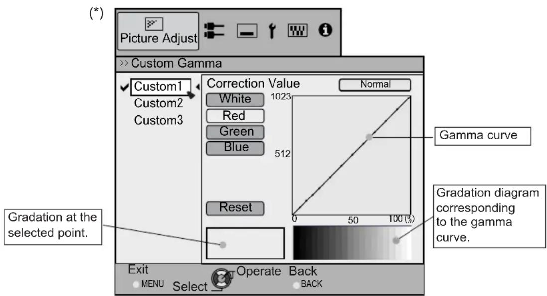
[1-2-2] Custom Gamma
| Custom 1~3 | [1] It is possible to select a gamma curve adjustment for Custom 1, 2, and 3 under the "Gamma" of the picture adjust and then save it.Please adjust to your preference.(*) Initial values of Custom 1, 2, and 3 are the same as for "Normal".(*) Please refer to the figure at the bottom of the menu in two frames for adjustment.(*) It is recommended that you read "Gamma Curve" (page reference: 56) for hints about adjustment. |
| Correction Value | You can choose to add the underlying gamma curve adjustment.(*) Can choose any setting, as the default gamma curve will always appear linear.Settings: Normal, A, B, C, D(brightens in particular dark to intermediate parts) 1.8 to 2.6 (darkens in particular dark to intermediate parts) in the range of values with increments of 0.1 [Normal] |
| Gamma Adjustment | The gamma curve for "green" is being displayed as being representative. If "white", "red," "green" or "blue" are selected, the corresponding color curves are displayed.Place the cursor on a gamma curve with 12 points with the buttons for left and right, and then use the buttons for up and down buttons to move those points up or down. |
| White | Red, green and blue can be adjusted at the same time. |
| Red | It is possible to adjust the gamma curve of red. |
| Green | It is possible to adjust the gamma curve for green. |
| Blue | It is possible to adjust the gamma curve for blue. |
| Reset | The same data as for the "Normal" mode are used.(*) When you exit the adjustment menu of Custom Gamma, please save the adjustment values.You can return to the original data, which should be saved. |
Adjustments and settings in the menu (continued)
[1-2-3] Color Management RS50 RS60
| Custom 1~3 | Set the 7 color axis (red / orange / yellow / green / cyan / blue / magenta) color as you like and save it then. For example you may want to change only the red color of roses. Please adjust to your preference. According to your adjustments, the input image in the background changes. It is possible to confirm the video image before adjustment by pressing the "HIDE" button of the remote control. |
| Pause | It is possible to display the input video image of the background being adjusted as a still picture. Settings: On, Off [Off] |
| On | Freezes the input video image. |
| Off | Unfreezes the input video image. |
| Color Selection | It is possible with the 7 colors of red, orange, yellow, green, cyan, blue and magenta to precisely adjust the hue, color saturation and brightness, and then save it. Please adjust to your preference. |
| Axis Position | Fine-tune the position of the central axis of the selected color further. Settings: -30 to 30 [0] |
| Hue | Adjust the hue. Settings: -30 to 30 [0] |
| Saturation Adjust the color saturation. Settings: (dim color), -30 to 30 (vivid colors) [0] | |
| Brightness Adjust the brightness. Settings: (dark) -30 to 30 (bright colors) [0] | |
[2] Input Signal
| HDMI | It is possible to set this if one selects the HDMI terminal to the submenu "[2-1] HDMI". |
| COMP. | This can be set if one selects the COMP. terminal to the submenu "[2-2] COMP." |
| PC RS50 RS60 be set if one selects the PC terminal to the submenu "[2-3] PC". | |
| Picture Position | Please adjust if the edges of the picture are partially missing due to the timing of horizontal and vertical synchronization signals. The value of the picture position depends on the input signal.(*) Depending on the input signal, it may be the case that not everything of the video image is displayed.(*) When there is a 3D input signal, adjustment is not possible. |
| Horiz. | This aligns the horizontal direction of the image position. |
| Vert. | This aligns the vertical positions of the image. |
| Aspect (Video) | (*) It is displayed when there is a video signal input.(*) If set to3D, ratio is fixed to 16:9.Settings: 4:3, 16:9, Zoom [16:9] |
| 4:3 | Sets the screen size of the image to 4:3. For HD signals, left and right sides are reduced. |
| 16:9 | Sets the screen size of the video image screen to 16:9. For SD signals left and right sides are expanded. |
| Zoom | Zooms the video images. (*) For HD signals, this cannot be selected. |
| Aspect (PC) | Sets the video image screen size when there is a PC video signal input.(*) Is displayed when there is a PC signal input.Settings: Auto, 1:1, Full [Auto] |
| Auto Positions the video image screen in the center of the display range, to fill the screen. | |
| Just | Depending on the size of the video screen, left and right black borders will be drawn.The video image screen size is displayed with the size of the input image.Depending on the input video image, the screen will become smaller or part of the input image off the screen is cut off. |
| Full It does not keep the aspect ratio of the video image screen and fills the entire screen. | |
Adjustments and settings in the menu (continued)
| Mask | It hides the upper, lower, left and right borders of the screen with a black mask. Can be individually adjusted vertically and horizontally. Please adjust to your preference. Setting: Off, 2.5%, 5%, Custom [Off] |
| Off Not masked. | |
| 2.5% | Compared to the original video images, around 2.5% around the video images are masked. |
| 5% | Compared to the original video images, around 5% around the video images are masked. |
| Custom | |
| Left | Compared to the original video images, around 5% of the video images are masked on the left side. Settings: 0 ~ 5% [0] |
| Right | Compared to the original video images, around 5% of the video images is masked on the right side. Settings: 0 ~ 5% [0] |
| Top | Compared to the original video images, around 5% of the video images are masked at the upper side. Settings: 0 ~ 5% [0] |
| Bottom | Compared to the original video images, around 5% of the video images are masked at the bottom side. Settings: 0 ~ 5% [0] |
| Progressive | Interlaced signals (480i/576i/1080i) are converted to progressive signals. Interpolates interlaced signal video images with video images from the surrounding. Please set to your preference. Settings: Auto, Off [Auto] |
| Auto | It is automatically detected if the 24p video images, which can be seen in the film screens, interlaced signals from the original video material or if they are the product of signal conversion and are interpolated accordingly. |
| Off The interpolation of video images as interlaced video signals, e.g. video material is done. | |
[2-1] HDMI
| Input | (*) It can be set when the HDMI terminal is selected. |
| Sets the dynamic range of the input video images (scale). Dark and bright areas, which are not matched to the range, might get brighter or darker. If you are unsure of the input signal dynamic range, please check under "Level Check".Settings: Standard, Enhance, Super White [Standard] | |
| Standard | It gets set if the dynamic image range of the gradation level of the input image is set to 16-235. In case of a video signal, please set it up here. |
| Enhanced | It is set if the dynamic range of the input video scale level is 0-255.If these are PC signals, please set them here. |
| Super White | It is set if the dynamic range of the input video scale level is 16-255.Please set the output to video equipment compatible with Super White for Super White-enabled DVD / BD etc. |
| Level Check | You can confirm the dynamic range of the input signal.A pattern as shown in the illustration is displayed in the four corners and center of the screen. Please compare the dynamic range of input signal with this pattern illustration and confirm. (*) The number in the illustration is the scale level. This number is not displayed. The illustration of the gradation in the figure is accentuated for explanatory purposes It is different from the actual scale level. |
| Color Space | It sets the color space of the input signal.Settings: Auto, YCbCr(4:4:4), YCbCr(4:2:2), RGB [Auto] |
| Auto YCbCr(4:4:4), YCbCr(4:2:2), RGB signals are automatically detected and configured.YCbCr (4:4:4) | Sets it if the input of the YCbCr(4:4:4) input video image signal is performed. |
| YCbCr (4:2:2) | Sets it if the input of the YCbCr(4:2:2) input video image signal is performed. |
| RGB | It is set when the RGB video signals input is performed. |
| Control with HDMI | Configured communication of the HDMI equipment controlSettings: On, Off [Off] |
Adjustments and settings in the menu (continued)
| 3D Format | Sets the format of the 3D input signal.Some signals may not be appended with 3D information themselves, and projection may fail if they are recognized as normal 2D signals.When this occurs, configure the settings manually.(*) It is recommended to read "On 3D" (reference page: 53) before watching 3D video images.Settings: Auto, Frame Packing, Side by Side, Top & Bottom, 2D [Auto] |
| Auto Is set automatically. | |
| Frame Packing | Select this if the 3D input signal is the frame pack method. |
| Side by Side | Select this if the 3D input signal is the side by side method. |
| Top and Bottom | Select this if the 3D input signal is the top and down method. |
| 2D | Projected as a 2D signal. |
[2-2] COMP.
| (*) It can be set when the COMP. terminal is selected. | |
| Color Space | It configures the input signal method of the component input terminal.Settings: Y Pb/Cb Pr/Cr, RGB [Y Pb/Cb Pr/Cr] |
| Y Pb/Cb Pr/Cr | It is set for the component video image input signal. |
| RGB | It is set for the RGB video image input signal. |
[2-3] PC RS50 RS60
| (*) Setting can be done when selecting a PC terminal. | |
| Auto Alignment | The picture position of Tracking and Phase are automatically adjusted. |
| Tracking | Adjusts the size and display of the horizontal direction and display area of the video images.(Depending on the signal, there is normally no need to be adjusted.) |
| Phase | Adjusts the flickering and blur of the video images.(Depending on the signal, there is normally no need to adjustment.) |
| Picture Position | Adjust the display of the picture position. |
| Horiz. Adjusts the horiz. of the video image. | |
| Vert. Adjusts the vertical position of the image. | |
[3] Installation
| Lens Control To Sub-menu "[3-1] Lens Control" | |
| Pixel Adjust To submenu "[3-2] Pixel Adjust" | |
| Installation Style | Matching the state of the projector's projection, one can switch horizontal and vertical flip / forward switch.Settings: Front, Ceiling Mount (Front), Rear, Ceiling Mount (RE) [Front] |
| Front | Front upright projection mode. |
| Ceiling Mount (F) | Ceiling/front projection mode. |
| Rear | Rear upright projection mode. |
| Ceiling Mount (R) | Ceiling/ rear projection mode. |
| Keystone | In regards to the projection plane, any occurring keystone distortion is adjusted in case the installation location is inclined.(*) There may be instances, when the video image - after having corrected keystone distortion - will not match the screen. The position with a shift correction of 0% position is an exception.(*) When there is a 3D input signal, adjustment is not possible. |
| Horizontal Adjusts the horizontal keystone.Settings: -40 to 40 [0] | |
| Vertical Adjusts the ve | rtical keystone.Settings: -30 to 30 [0] |
Adjustments and settings in the menu (continued)
| Anamorphic | The video images are projected after being enlarged in the vertical direction of the panel resolution. This setting is used when one uses the anamorphic lens to enlarge them in the horizontal direction. (*) Anamorphic mode cannot be set when there is a 3D signal input. If a 3D signal is fed in when Anamorphic mode is set to A or B, Anamorphic mode is automatically turned Off. Settings: A, B, Off [Off] |
| A | Video with an aspect ratio of 2.35:1 is enlarged in the vertical direction of the panel resolution and then projected. |
| B | Video with an aspect ratio of 16:9 are displayed by reducing them in the horizontal direction, without changing their size in the vertical direction. |
| Off | Used when watching video images other than those with a 2.35:1 aspect ratio while using an anamorphic lens. 2.35:1 video images are projected without any changes. (Black bands appear on all sides) |
| Screen Adjust | It corrects the white balance fault according to the reflective properties of the projection screen. Please adjust to your preference. |
| Black Level | Sets the black level when used indoors. Settings: 0 to 10 [0] |
[3-1] Lens Control
| It controls each motorized functions of the lens during the projector-installation. | |
| Focus | This function is used to adjust the focus. |
| Zoom | This function is used to adjust the zoom. |
| Shift | This function is used to adjust the shift. |
| Lens Cover | This function is used to set if the lens cover should be linked with a power supply for opening/closing, or if it should be left open.Settings: Auto, Open [Auto] |
| Auto This opens/closes the lens cover when it is linked to on/off of a power supply.Open Regardless if the power supply is on/off, the lens cover is always open. | |
| Image Pattern | It is possible to adjust the projection screen during adjustment of the focus zoom shift.Settings: On, Off [On] |
| On During the adjustment, the image pattern is displayed.The image pattern is displayed in conjunction with the above setting items.Off The external input signal is displayed without displaying the image pattern. | |
| Lock | This sets the lens control to on/off.Settings: On, Off [Off] |
| On It is not possible to adjust the above setting items. If the remote control button "LENS"button is pressed, a warning message is issued.Off This functions as lens control function. | |
[3-2] Pixel Adjust
| This fine tunes each slight color errors in the horizontal/vertical directions of the video images in units of 1 pixel. (*) It is impossible to match all image pixels on the screen. Due to the equipment, there will always be some gaps. (*) In case the image is reversed, or upside-down, the horizontal and vertical directions are reversed. (*) Please perform adjustments on a clear still picture. (*) For fine tuning, the effects of adjustments may be difficult to understand for some video images. |
Adjustments and settings in the menu (continued)
| Horiz. Red | (Move red to the left) 1 to 5 (move red to the right) [3] |
| Horiz. Green | (Move green to the left), 1 to 5 (move red to the right) [3] |
| Horiz. Blue | (Move blue to the left) 1 to 5 (move red to the right) [3] |
| Vert. Red | (move red down) 1 to 5 (move red up) [3] |
| Vert. Green | (Move green down) 1 to 5 (move green up) [3] |
| Vert. Blue | (move blue down) 1 to 5 (move blue up) [3] |
[4] Display Setup
| Back Color | Sets the color of the background, which is displayed without an input signal. Settings: Blue, Black [Blue] |
| Blue | Sets the background color to blue. |
| Black | Sets the background color to black. |
| Menu Position | Sets the picture position of the menu. Please set to your preferred position Navigate the menu by pressing the left or right keys when you have selected an item. Moreover, if one presses the button [OK], an image illustration appears at the position of the menu. The highlighted position in the illustration moves by use of the left and right keys. If one presses [OK], the menu moves to the highlighted position. If you press the key to the right, the menu will move starting from the top left -> top right -> central -> bottom right -> bottom left and then back to the upper left. By pressing of the left key, the menu moves in the opposite direction. [Upper left] |
| Menu Display | Sets the time for the menu to be displayed. Settings: 15 sec, On [On] |
| 15 sec | If there is no menu operation for 15 seconds, the menu display vanishes. |
| On | Display always. |
| Line Display | Configures if input is displayed or not when input is switched. value: 5 sec, on [5 sec] |
| 5 sec | Displays for 5 seconds. |
| Off | Not displayed. |
| Source Display | Configures whether or not to display the signal, when the input is switched. Settings: On, Off [On] |
| On | Display. |
| Off | Not displayed. |
| Logo | Configures whether or not to display the "D-ILA" logo upon activation. Settings: On, Off [On] |
| On | Displayed for 5 seconds. |
| Off | Not displayed. |
[5] Function
| Trigger | Configures 12V output to an external screen equipped with a trigger function. Settings: Off, On(Power), On(Anamo) [Off] |
| Off | No output. |
| On (Power) When turned on, control signals (12V) from the trigger terminal are emitted. | |
| On (Anamo) | Control signals (12V) are emitted when the Anamorphic mode is set from "Off" to "A" or "B". If the Anamorphic mode is set to "A" or "B", the operation in this state equals "On (Power)". |
| Off Timer | Sets Off Timer function and its time.* If there are no operations, the unit powers off automatically.* It powers off automatically even while projecting an image. Settings: Off, 1 hour, 2 hours, 3 hours, 4 hours [Off] |
Adjustments and settings in the menu (continued)
| Off | Power is not turned off. |
| 1 Hour | Power is turned off automatically after 1 hour. |
| 2 Hours | Power is turned off automatically after 2 hours. |
| 3 Hours | Power is turned off automatically after 3 hours. |
| 4 Hours | Power is turned off automatically after 4 hours. |
| High Altitude Mode | Set to use at low pressure locations (900m above sea level).Settings: On, Off [Off] |
| On | Set. |
| Off | Do not set. |
| CommunicationTerminal RS50 RS60 | Sets the used control terminal. It is not possible to use it at the same time.Settings: RS-232C, LAN [RS-232C] |
| RS-232C Sets the RS-232C terminal.LAN Sets the LAN terminal. | |
| Network RS50 RS60 | It is displayed, if the setting of the "Communication terminal" to the submenu "[5-1]Network" is set to "LAN". |
| Lamp Reset Reset of the lamp use time to "0". | |
[5-1] Network RS50 RS60
| DHCP Client | Sets the DHCP client. Settings: On, Off [Off] |
| On | Obtains automatically an IP address from within the connected network's DHCP server.* The automatic retrieval starts with the "Set" within the menu. |
| Off | The network settings are being done manually. |
| IP Address | Sets the IP address. [192.168.0.2] |
| Subnet Mask | Sets the subnet mask. [255.255.255.0] |
| Default Gateway | Sets the default gateway. [192.168.0.254] |
| MAC Address | Displays the MAC address of the unit. |
| Set | [5-1] Reflects the network setting. |
[6] Information
| Displays upon HDMI/COMP. input | |
| Input | Displays video image input terminal. |
| Source | Displays the name of the input source. |
| Deep Color | Displays the color bit depth concerning an input video image signal.* When you input YCbCr (4:2:2), it is not displayed.* When there is information about DeepColor from the source device, it is displayed. |
| Lamp Time | Displays the lamp use time. |
| Displays upon PC input | |
| Input | Displays video image input terminal. |
| Resolution | Displays image resolution. |
| H Frequency | Displays the H Frequency. |
| V Frequency | Displays V Frequency. |
| Deep Color | Displays the color bit depth concerning an input video image signal.* When you input YCbCr (4:2:2), it is not displayed.* When there is information about DeepColor from the source device, it is displayed. |
| Lamp Time | Displays the lamp use time. |
Operation guide (glossary)
Gamma Curve
The description of the gamma curve that assumes a gamma curve unit. Please read the relevant detailed description and professional books.
The gamma curve of the projector to the input video signal determines for each color the relative value of its light output.
The value of the input video image signal is displayed as a percentage - with both being displayed in % as units - of the maximum light input signal for brightness and the brightness output value as a percentage of the maximum output value of each color or the projector. In relation to the signal value of 50% of the input, it projects with brightness output value of 50%. However, a light output value of 0% is not completely black and neither no projection. As the possibility of the projector to reproduce blackness is limited, it will be actually slightly brighter.
The input video image signal value becomes a continuous curve of 0% to 100% for the gamma curve, which can be set with the projector. Moreover, it is impossible to get only one light output value for the input video image signal value.
The gamma curve can be set for each color, i.e. red, green and blue. By selecting the white color, the 3 colors can be adjusted at the same time.
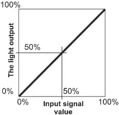
line
| Input signal value | The light output | | ------------------ | ---------------- | | 0% | 0% | | 50% | 50% | | 100% | 100% |A larger angle of inclination of the gamma curve leads to a greater gap of the
light output value of that area and makes it easier to distinguish the video images. A low angle of inclination leads, on the contrary, to the difference in that area becoming smaller, so that the video images are harder to distinguish. If it is impossible to get an inclination angle, so that it is chosen to become horizontal, the gap in that area vanished and it might be impossible to distinguish the video images.
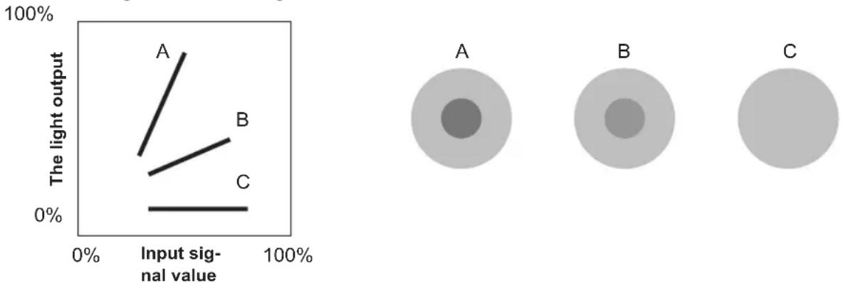
Suppose you knew the inclination of the input video image signal values of the watched video images, and would increase the slope of the portion of this area and attenuate the slope of other areas. It would then be easier to determine the video images. Also, if you did not know the inclination of the input video image signal value of the watched video images, adjustment would be difficult. However, there are some trends of the distribution of the input video image signal value depending on the type of video content. As some typical examples are prepared in the [Gamma] (Reference Page: 46), it is recommended to perform similar settings before watching.
Some methods about how to adjust the gamma curve are presented here, but in reality one can think of various adjustment methods, for example where red, green and blue are individually adjusted. In your own image creation, please enjoy the process of trial and error.
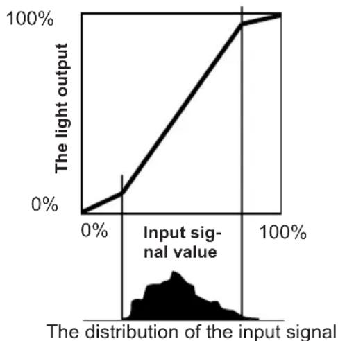
line
| Input signal value | The light output | | ------------------ | ---------------- | | 0% | 0% | | 100% | 100% |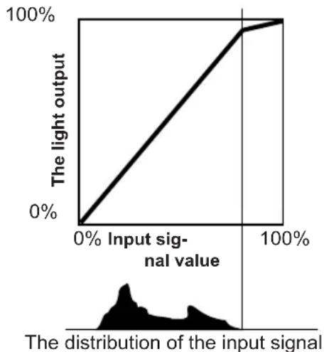
line
| Input signal value | The light output | | ------------------ | ---------------- | | 0% | 0% | | 100% | 100% |Description of the 3D method
This is a description for the 3D-method using this unit, 3D-glasses (sold separately: PK-AG1-B) and an 3D synchro emitter (sold separately: PK-EM1). Set the 3D TV and 3D compatibility software to an appropriate
viewing standard. For viewing, a separate unit compatible with 3D playback is needed. For detailed description of other 3D methods, please read specialized books on this topic. (For the sake of explanation, a simplified and exaggerated picture is used.)
The 3D scheme of this unit utilizes the principle of binocular parallax. It projects with the frame sequential method, where separately alternating images are produced for the left and right eye. Opening and closing of 3D glasses fitted with liquid crystal shutters are controlled in such a way, that video images corresponding to the right/left eye and are only visible for the respective eye. As a result, one can watch three-dimensional images.
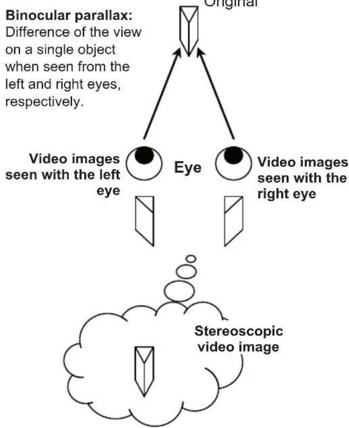
flowchart
graph TD
    A["Original"] --> B["Eye"]
    A --> C["Video images seen with the left eye"]
    B --> D["Stereoscopic video image"]
    C --> D
    style A fill:#f9f,stroke:#333
    style B fill:#ccf,stroke:#333
    style C fill:#cfc,stroke:#333
Due to the difference of the video images both eyes see, the brain perceives them in a stereoscopic way. The video images that can be seen by the respective eyes are artificially produced. Due to the exposure of the eyes to the respective video images, the brain is induced to create a stereoscopic image, which is not present as a real object. In other words, it is a use of virtual images.

CAUTION
- Please stop watching at once if you do not feel well and consult a physician if necessary.
• People who already have a kind of photosensitivity, sufferers from heart disease, and people in poor physical condition should not watch 3D video images of this device, which makes use of 3D glasses. - It is recommended that you take a break periodically. Length and frequency of the required break differ due to individual differences. Please judge for yourself.

CAUTION
- The comprehensive brain function to judge stereoscopic vision and which include a feeling for real distances, develops while growing up by touching and seeing real objects, but in early childhood, it is still in an underdeveloped state. Even though there are individual differences, children under 5 are still developing. Letting them frequently watch virtual 3D video images can be an obstacle for the development of a comprehensive three-dimensional feel.
- For younger children may suddenly become sick, because they continue watching without realizing symptoms like 3D sickness or deterioration of health until after watching 3D images. Please accompany your while it watches. And please be careful when it comes to your child's bodily condition and state.
Separate images which can be seen by the right eye and left eye, respectively, are taken and produced separately. Therefore, the image for the left eye is only visible to the left eye, and the images for the right eye only or the right eye. The Human brain perceives stereoscopic images based on image information on both sides.
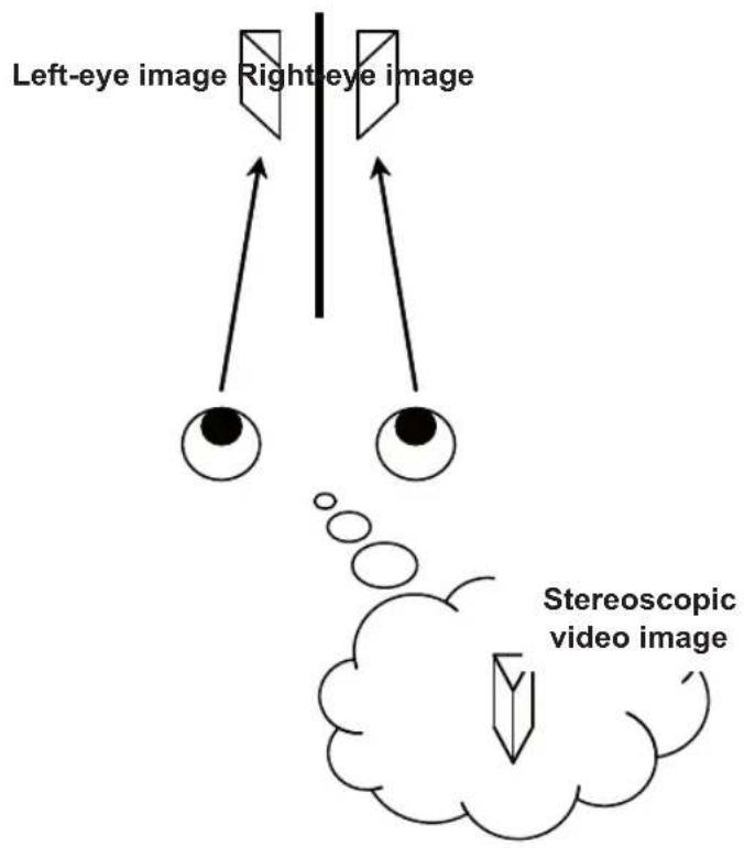

CAUTION
In most cases, 3D images taken or produced are horizontally arranged respectively. If these images were not horizontally arranged for left and right eye movement when watching, the brain could not perceive a stereoscopic image, but would still recognize a double image. As such video images can cause 3D sickness, please do not hold the 3D glasses slanted relative to the video images.
The closer one looks at stereoscopic images, the greater the binocular disparity, which means greater perception of outward projection. At the same time, the focus has to fit the screen, but the projecting image and the focus cause a great contradiction. This causes visual fatigue and discomfort.

CAUTION
Please watch from a distance three times the height of the screen. For example, for a projection size of 120, it should be approximately 4.5m, and for an 80-type, it should be around of 3 m. Please refer to page 19, where one can find a table with the screen seizes and at the same height. Choosing a distance closer than recommended may cause eyestrain.
The frame sequential method is a way of displaying video images left and right sequentially. The projector projects the video images used for the left- and right eyes onto the screen. The video images for the left and right side are only visible with the respective eye, as the left and right side of the 3D glasses are opened and shut by a liquid crystal shutter. As a result, the left and right images are seen by the eye and show a 3D image.
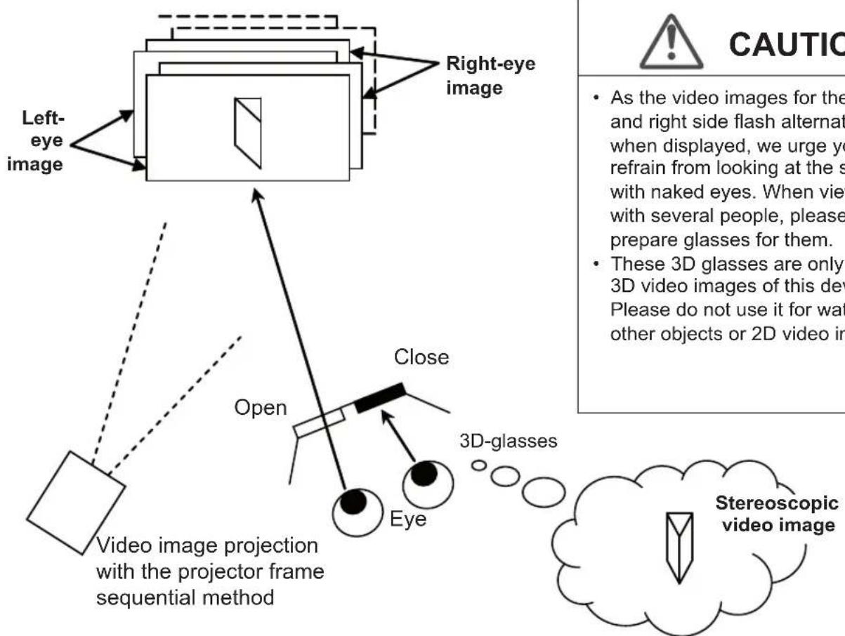
flowchart
graph TD
    A["Left-eye image"] --> B["Image with projection"]
    B --> C["Open"]
    C --> D["Close"]
    D --> E["Eye"]
    E --> F["3D-glasses"]
    F --> G["Stereoscopic video image"]
    style A fill:#f9f,stroke:#333
    style B fill:#ccf,stroke:#333
    style C fill:#cfc,stroke:#333
    style D fill:#fcc,stroke:#333
    style E fill:#cff,stroke:#333
    style F fill:#ffc,stroke:#333
    style G fill:#fcf,stroke:#333
In order to match the timing of the display of video images and the timing of the opening/closing of the 3D glasses liquid crystal shutters and it is necessary to show to the eyes only those video images, for the left or right eye, respectively, the projector of this unit sends these timing data from the 3D synchro emitter to the 3D glasses with infrared rays.

CAUTION
- In regard to the 3D emitter, please direct the 3D glasses in such a way towards it, that the infrared rays can directly reach the 3D glasses.
• In the following cases, it may not work correctly.
- If you are near infrared communication equipment or lighting equipment.
- If the 3D-glasses do not face to the 3D synchro emitter.
- Depending on the use of 3D emitters, it may be possible that its operation might influence the operation of other devices with infrared communication.
Replacing the Lamp
The lamp is a consumable item. If the image is dark or the lamp is turned off, replace the lamp unit.
When the lamp replacement time approaches, a message is displayed on the screen and the condition is indicated by the indicator. (Reference page: 16 to 17, 68)

CAUTION
Do not insert your hands into the opening of the lamp!
This could cause obvious deterioration of the equipment's function, wounds and electric shocks.
Do not replace the lamp immediately after the unit has been used, and allow a cooling period of 1 hour or more before replacement. The temperature of the lamp is still high and this may cause a burn.
Do not apply shock to the lamp unit. It may cause lamp blowout.
Do not use flammable air duster to clean the internal parts of the unit. This may cause fire.
MEMO
Usable Lamp Life
When using the "Lamp Power" set at "Normal", the lifetime of the lamp will be approximately 3000 hours.
This is an average lifetime and cannot be guaranteed.
The lamp life may not reach 3000 hours depending on the operating conditions.
When the lamp has reached the end of its usable life, deterioration progresses rapidly.
If the picture becomes dark, the tint becomes strange, or the image flickers, promptly the lamp unit for a new one.
Purchasing the Lamp Unit
Please consult your authorized dealer.
Lamp Unit
Part No.: PK-L2210U
Lamp replacement procedure
1 Remove the power plug from the outlet
2 Remove the lamp cover
Remove the screws with a ⊕ screwdriver.
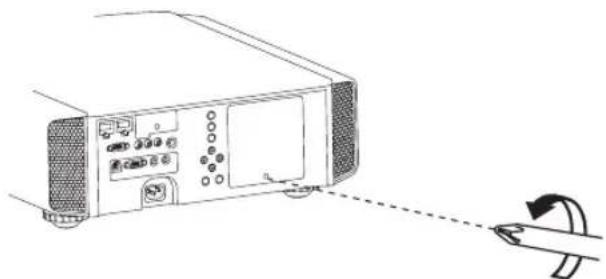
natural_image
Diagram of a computer monitor with ports and an arrow indicating rotation (no text or symbols)3 Loosen the screws on the lamp unit
Loosen the screws with a ⊕ screwdriver.
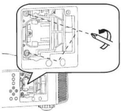
natural_image
Diagram of a computer monitor internal structure with an airplane icon pointing to its screen (no text or symbols present)4 Pull out the lamp unit
Grasp the handle and pull out the lamp unit.
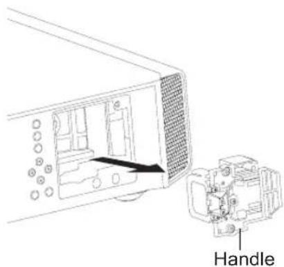
5 Install the new lamp unit
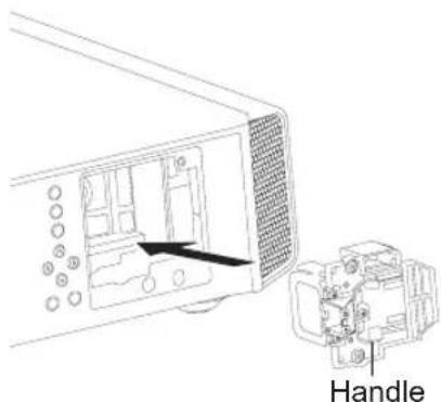
6 Tighten the screws of the new lamp unit
Tighten the screws with a ⊕ screwdriver.
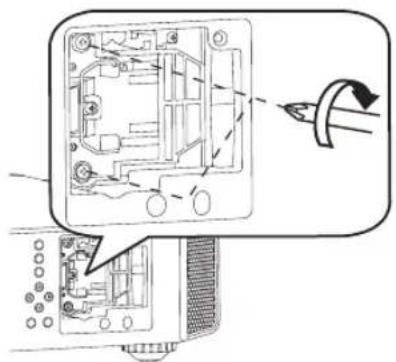
natural_image
Diagram of a device interior showing internal components and a directional arrow indicating rotation (no text or symbols present)7 Attach the lamp cover
Insert the top part (with 2 claws) of the lamp cover into the unit.
Fasten the screws with a +screwdriver.
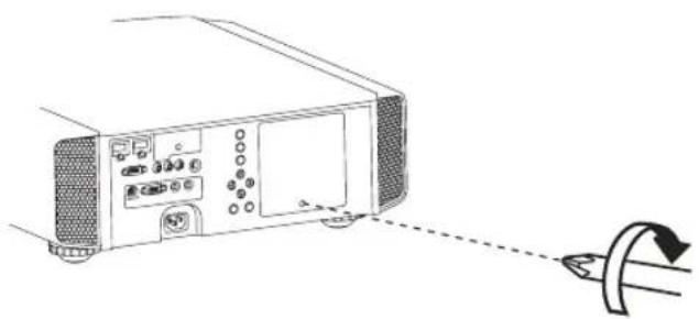
natural_image
Diagram of a projector unit with a curved arrow indicating light direction (no text or symbols present)
CAUTION
Use only genuine replacement parts for the lamp unit. Also, never attempt to reuse an old lamp unit. This may cause a malfunction.
Do not touch the surface of a new lamp. This may shorten the lamp life and cause lamp blowout.
MEMO
After Replacing the Lamp
Do not place the removed lamp unit at locations that is reachable by children or near combustible items
Dispose used lamp units in the same way as fluorescent lamps Follow your local community rules for disposal.
Replacing the Lamp (Continued)
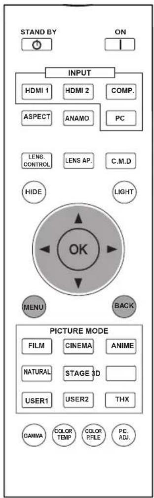
RS50 RS60
Resetting lamp Time
After replacing a new lamp unit, please reset the lamp time. Description of two methods.
Reset the lamp time from the menu screen.
1 Display the setting menu
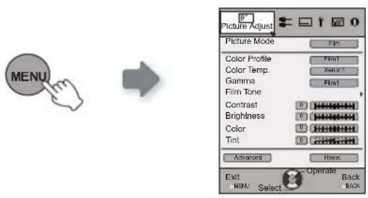
2 Select“Function” → “Lamp Reset”
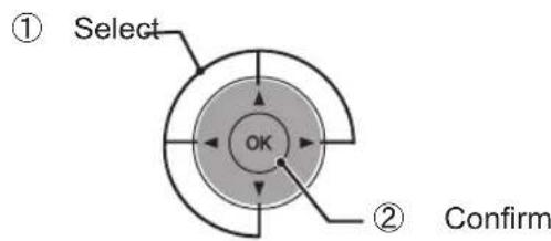
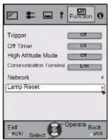
3 Re-confirm
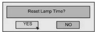
"Yes" and the lamp time is set to zero. Moreover, one returns to the previous menu.
Reset the lamp time by remote control.
1 Insert the power plug to the power outlet

2 Must operate with the remote control in the standby mode (the projector is powered, but is not turned on).
Press in the order as shown.
Press each button within 2-second intervals and press the last button for 2 seconds or more.

flowchart
graph LR
    A["BACK"] --> B["OK"]
    B --> C["HIDE"]
    C --> D["Press for 2 seconds or more"]
[STANDBY/ON] indicator and [LAMP] indicator blink alternately for 3 seconds. After that, the unit switches to standby mode.
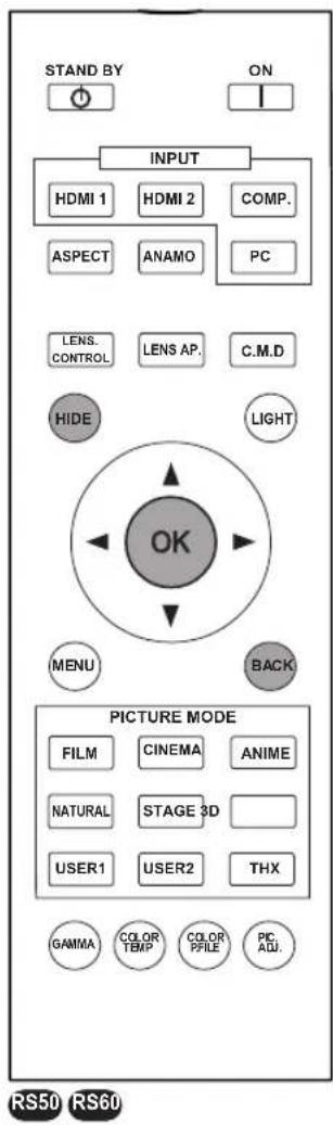


CAUTION
Reset the lamp time only when you have replaced the lamp. Never reset the service time when the lamp is still in use. Otherwise, the approximate standard for gauging replacement time may be inaccurate and lamp blowout may occur.
Method for cleaning and replacing filters
Clean the filter regularly or air intake efficiency may deteriorate and malfunction may occur.
1 Remove the inner filter.
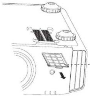
natural_image
Diagram of a mechanical component with labeled parts and an arrow indicating direction (no text or symbols present)Lift up while pushing the claw
2 Clean the filter.
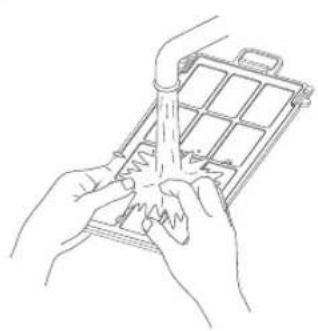
natural_image
Line drawing of hands using a tool to spread or spread material inside a grid-like device (no text or symbols)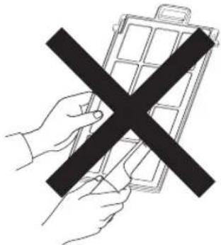
natural_image
Illustration of a hand holding a device with a black X symbol (no text or symbols present)Wash the filter with water and dry it in a shaded area. In extremely soiled cases, using a neutral detergent is recommended. Put on rubber gloves when using a neutral detergent.
After washing the filter with water, make sure that it is completely dry before reinstalling. Otherwise electric shock or malfunctions may occur.
Do not clean the filter with a vacuum cleaner or air duster. The filter is soft and may be damaged.
③ Reinstall the inner filter.
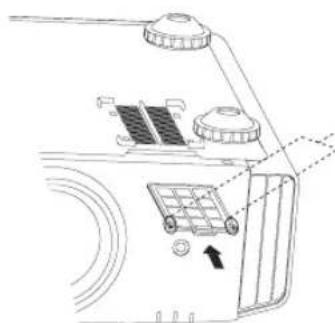
natural_image
Diagram of a mechanical device with labeled components and directional arrows (no readable text or symbols)Check that the left and right claws are locked onto the unit

CAUTION
Pull the power plug from the power outlet.
Please turn this unit and if you put in on a bed or a table, first place something soft like a piece of cloth below.
Then you can put it on top of it. Otherwise, it may cause scratches on this unit.
MEMO
If the filter is damaged or too dirty to be cleaned.
Replace with a new filter. A dirty filter will dirty the internal parts of the unit and cause shadows on the video image. To purchase a new filter or when it is dirty in the internal parts, consult your authorized dealer.
Inner Filter
Part No.:
Replacement Filter:
PC010661199
MEMO
Troubleshooting
Before sending the unit to your authorized dealer for repair, please check the following points.
The following situations are not malfunctions.
You do not need to worry about the following situations if there is no abnormality on the screen.
Part of the top surface or front of the unit is hot.
A creaking sound is heard from the unit.
An operating sound is heard from the inside of the unit.
Color smear occurs on some screens.
Perform the following operations when the unit is unable to operate normally due to external static or noise.
① When the unit is in standby mode, please pull out the power plug, then insert again.
② Press the power button on the unit to turn on the power again.
A sound may be heard when the lamp is off but there is no danger.
D-ILA device is manufactured using high-precision technology but there may be some missing pixels or pixels that remain permanently lit up.
| Power is not supplied | ||
| Is the power cord disconnected? | Insert the power cord (plug) firmly. | Reference page: 31 |
| Is the lamp cover properly shut? | Remove the power plug when the unit is in standby mode and close the lamp cover properly. After that, insert the plug again. | Reference page: 61 |
| Is the lamp in Cool Down mode? | After the Cool Down mode is complete, turn on the power again. | Reference page: 33 |
| Video image does not appear | ||
| Is the correct external input selected? | Select the correct external input. | Reference page: 32 |
| Is the AV device properly connected? | Connect the AV device properly. | Reference page: 25 to 30 |
| Is the power of the AV device turned on? | Turn on the power of the AV device and play the video. | Reference page: 32 |
| Are the correct signals being output from the AV device? | Set the AV device properly. | Reference page: 25 to 30 |
| Is the setting of the input terminal correct? | Set “COMP.” and “HDMI” in the setting menu according to the input signal. | Reference page: 51 to 52 |
| Is the video image temporarily hidden? | Press the [HIDE] button to display the video image again. | Reference page: 36 |
| Remote control does not work | ||
| Are batteries installed correctly? | Match the polarities (⊕ or⊖) correctly when inserting the batteries. | Reference page: 19 |
| Are batteries exhausted? Replace with new batteries. | Reference page: 19 | |
| Is there an obstructive object between the remote control and remote sensor? | Remove any obstructive objects. | Reference page: 23 |
| Is the remote control held too far away from the unit? | Hold the remote control closer to the sensor when using. | Reference page: 23 |
| The picture cannot be projected | ||
| Will the picture flicker and become invisible with HDMI input? | Please use a short HDMI cable. | Reference page: 26 |
| The image cannot output by HDMI terminal | ||
| Is the setup of “Control with HDMI function “Off”? | Set up the “Control with HDMI function to Off . | Reference page: 51 |
normally.
| Color does not appear or looks strange | ||
| Is the image correctly adjusted? | Adjust Color and Tint in the setting menu. | Reference page: 47 |
| Video image is fuzzy | ||
| Is the focus correctly adjusted? Adjust the focus. | Reference page: 32 | |
| Is the unit placed too near or too far away from the screen? | Set the unit at a correct distance from the screen. | Reference page: 21, 23 |
| Video images are missing | ||
| Has setting been performed for screen mask? | Set Mask in the setting menu to Off. | Reference page: 35Reference page: 51 |
| Is the display out of position? | Alter the Picture Position value in the setting menu to ensure that images are not missing. | Reference page: 50 |
| Projected image is dark | ||
| Is the lamp near exhaustion? | Check the lamp time on the information menu. Prepare a new lamp unit or replace as soon as possible when the lamp is near exhaustion. | Reference page: 60 to 63 |
| The unit works when power is turned on but stops abruptly after a few minutes | ||
| Are the air inlets and exhaust vent blocked? | Remove the power plug when the unit is in standby mode and remove any blocking object. After that, insert the plug again. | Reference page: 3, 14 |
| Is the filter dirty? Clean the filter. | Reference page: 64 | |
| Power is cut off suddenly | ||
| Has setting been performed for off timer? | Set Off Timer in the setting menu to Off . | Reference page: 54 to 55 |
In case this message is displayed
| Message Cause (Details) | |
 | No device is connected to the input terminal.The input terminal is connected but there is no signal.→ Input the video signals. |
 | A video signal that cannot be used in this unit has been input.→ Input video signals that can be used.* The names of input terminals such as COMP. will be displayed in yellow |
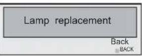 | This message is displayed when the accumulated lamp time has exceeded 2900 hours.To clear the message, press the [Back] button.→ Get ready a new lamp unit and replace as soon as possible. Reset the lamp time after replacing the lamp. (Reference page: 60 to 63) |
RS-232C Interface
It is possible to control this machine, if it is connected by an RS-232C cross cable (D-Sub9 pin) to a PC. Otherwise, this machine can be controlled via a computer network by connecting it with a LAN cable and sending of control commands. Please use it after you have understood this by reading professional books, or by discussing it with a system administrator.
RS-232C Specifications
This unit
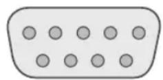
| Pin No. Signal Function Signal Direction | |||
| 2 RxD | Receive data PC→This unit | ||
| 3 TxD | Transmit data This unit→PC | ||
| 5 GND | Signal ground | - | |
| 1,4,6 - 9 N/C -- | |||
PC refers to the controller such as a personal computer.
| Mode | Non-synchronous |
| Character Length | 8 bit |
| Parity | None |
| Start Bit | 1 |
| Stop Bit | 1 |
| Data rate | 19200 bps |
| Data format | Binary |
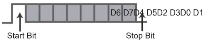
TCP/IP-connection
Before you can control it via LAN, you have to establish a TCP-connection via a "3-way-handshake". It is necessary for a connection authentication to send from the projector "PJ_OK" and - within 5 seconds after sending a "PJREQ" – to receive "PJACK". Please perform this operation – after confirming the operating status of the projector - again after establishment of a TCP connection, if you cannot send within 5 seconds "PJ_NG" or could not receive "PJNAK".
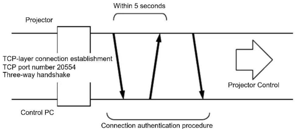
flowchart
graph TD
    A["Projector"] --> B["TCP-layer connection establishment<br>TCP port number 20554<br>Three-way handshake"]
    B --> C["Control PC"]
    C --> D["Connection authentication procedure"]
    D --> E["Within 5 seconds"]
    E --> F["Projector Control"]
RS-232C Interface (Continued)
Command Format
The command between this unit and the computer consists of "Header", "Unit ID", "Command", "Data" and "End".
Header (1 byte), Unit ID (2 bytes), Command (2 bytes), Data (n bytes), End (1 byte)
Header
This binary code indicates the start of communication.
| Binary code | Type Description | |
| 21 Operating | command PC | This unit |
| 3F Response | command PC | This unit |
| 40 Reference | command This unit | PC |
| 06 ACK | This unit PC(When the command is accepted without error, it returns to PC) |
Unit ID
This code specifies the unit. The binary code is fixed at 8901.
Command and data
Operating command and data (Binary code)
| Command Type | Description | |
| 0000 | Connection check | Check whether communication is available between this unit and the PC during standby. |
| 5057 | Power supply | During standby31: Turn on the power.During power on30: Turn off the power. (Standby mode) |
| 4950 | Input | During power on32: COMP.33: PC RS50 RS6036: HDMI 137: HDMI 2 |
| 5243 | Remote Control | Sends the same code as the supplied remote control.“Remote control code” (Reference page: 71) |
Reference command and data (Binary code)
| Command Type Data description | ||
| 5057 | Power supply | During standby or power on30: Standby mode31: Power-on mode32: During Cool Down mode34: Warning mode |
| 4950 | Input | During power on32: COMP.32: PC RS50 RS6036: HDMI 137: HDMI 2 |
End
This code indicates the end of communication. The binary code is fixed at
Remote control code
Binary code is sent during communication.
| Remote control button name | Binary code | Remote control button name | Binary code |
| ▲ | 37 33 30 31 NATURAL 37 33 36 41 | ||
| ▼ | 37 33 30 32 USER 1 37 33 36 43 | ||
| BACK 37 33 30 | 33 USER 2 37 33 36 44 | ||
| ON 37 33 30 | 35 USER 3 37 33 36 45 | RS40 | |
| STAND BY 37 33 | 30 36 THX 37 33 36 46 | RS50 RS60 | |
| HIDE 37 33 31 | 44 HDMI 1 37 33 37 30 | ||
| LENS.AP. | 37 33 32 30 HDMI 2 37 33 37 31 | ||
| MENU | 37 33 32 45 | PIC.ADJ. | 37 33 37 32 |
| OK 37 33 32 | 46 INFO. | 37 33 37 34 RS40 | |
| LENS CONTROL | 37 33 33 30 GAMMA | 37 33 37 | 35 |
| ▶ | 37 33 33 34 | C.TEMP | 37 33 37 36 |
| ◀ | 37 33 33 36 ASPECT | 37 33 37 | 37 |
| PC RS50 RS60 | 37 33 34 36 | 3D | 37 33 38 37 |
| COMP. 37 33 34 | 44 | COLOR PROFILERS50 RS60 | 37 33 38 38 |
| ANIME 37 33 36 | 36 C.M.D | 37 33 38 | 41 |
| STAGE | 37 33 36 37 ANAMO 37 33 43 35 | ||
| CINEMA | 37 33 36 38 COLOR SPACE | 37 33 | 43 44 |
| FILM | 37 33 36 39 |
RS-232C Interface (Continued)
RS-232C Communication Examples
This section shows the communication examples of RS-232C.
Operating command
| Type Command Description | ||
| Connection check | PC→This unit: 21 89 01 00 00 0AThis unit→PC: 06 89 01 00 00 0A | Connection check. |
| Power (On) | PC→This unit: 21 89 01 50 57 31 0AThis unit→PC: 06 89 01 50 57 0A | When power is turned on from standby mode. |
| Power (Off) | PC→This unit: 21 89 01 50 57 30 0AThis unit→PC: 06 89 01 50 57 0A | When power is turned off (standby mode) from power-on mode. |
| Input (COMP.) | PC→This unit: 21 89 01 49 50 32 0AThis unit→PC: 06 89 01 49 50 0A | When video input is set to component. |
| Remote Control (MENU) | PC→This unit: 21 89 01 52 43 37 33 32 45 0AThis unit→PC: 06 89 01 52 43 0A | When the same operation as pressing the [MENU] button on the remote control is made |
Reference command
| Type Command Description | ||
| Power (On) | PC→This unit: 3F 89 01 50 57 0AThis unit→PC: 06 89 01 50 57 0AThis unit→PC: 40 89 01 50 57 31 0A | When information of power-on mode is acquired. |
| Input (HDMI 1) | PC→This unit: 3F 89 01 49 50 0AThis unit→PC: 06 89 01 49 50 0AThis unit→PC: 40 89 01 49 50 36 0A | When information of HDMI 1 input is acquired. |
Copyright and Caution
HDMI ^TM
HIGH-DEFINITION MULTIMEDIA INTERFACE
About Trademarks and Copyright
HDMI, HDMI logo and high definition multimedia interface are trademarks or registered trademarks of HDMI Licensing LCC.
Caution
D-ILA Device Characteristics
Do not project still pictures or pictures that have still segments for a long period of time. The still parts of the picture may remain on the screen.
Take special notice of images on the screens of video games and computer programs. There is no problem when playing normal video images such as movies.
When Unit is Unused for a Long Time
Prolonged disuse of the unit may effect an error on the functions. Turn on the power occasionally and operate the unit.
Usage Environment
Avoid direct exposure of screen to direct sunlight and illumination. Block light using a curtain. Images can be well projected by darkening the brightness of the room.
Do not use this unit in rooms with cigarette smoke or oily smoke. This may cause the unit to malfunction.
Parts Replacement
This unit contains parts (optical part, cooling fan, etc.) that require replacement to maintain its functioning. The estimated time for parts replacement varies greatly depending on the usage and environment. Please consult your authorized dealer for replacement.
Maintenance Procedures
Dirt on the cabinet
Gently clean dirt on the cabinet with a soft cloth. In the case of heavy soiling, soak a cloth in water, wring dry and wipe, followed by wiping again with a dry cloth. Pay attention to the following as the cabinet may deteriorate in condition or paint may come off.
- Do not wipe with thinner or benzene.
- Do not spray with volatile chemicals like insecticide.
- Do not allow prolonged contact with rubber or plastic products.
Dirt in the air inlets
Use a vacuum cleaner to suck up the dirt. Otherwise, use a cloth to wipe off the dirt. If dirt is allowed to accumulate in the air inlets, the internal temperature cannot be adjusted and this may cause a malfunction.
Dirt on the lens
Clean the dirt using commercial blowers or lens cleaning papers for cleaning glasses and cameras. Do not use fluid-type cleaning agents. This may lead to peeling of the surface coating film. (Reference page: 14)
Specifications
| Product Name | D-ILA Projector | |
| Model Name | DLA-RS40-B, DLA-RS50-B, DLA-RS60-B *1 | |
| Display Panel/Size | D-ILA device *2 *30.7" (1920pixels x 1080pixels) x 3 (Total no. of pixels: Approx. 6.22million) | |
| Projection Lens | 2.0 x power zoom lens (1.4:1 to 2.8:1)(Zoom/Focus: Power) | |
| Light-source Lamp | 220 W Ultra-high pressure mercury lamp [Part No. :PK-L2210U]Average lifespan: 3000 hours (normal mode) | |
| Screen Size | Approx. 60" to 200" (Aspect ratio: 16:9) | |
| Projection Distance Approx. | 1.8m to 12m | |
| Analog Video Input Format | 480i, 480p, 576i, 576p, 720p/50 Hz, 720p/60 Hz, 1080i/50 Hz1080i/60 Hz | |
| Digital Video Input Format | 480i, 480p, 576i, 576p, 720p/50 Hz, 720p/60 Hz, 1080i/50 Hz1080i/60 Hz, 1080p/24 Hz, 1080p/50 Hz, 1080p/60 HzPC compatible signals (Reference page: P24) | |
| Resolution 1920 dots x 1080 dots | ||
| Input terminal | ||
| Video Input | 1 system, RCA pin jack 3Y:1.0Vp-p, 75ΩPb/Cb, Pr/Cr:0.7Vp-p, 75Ω* Also supports R / G / B Sync on G | |
| HDMI Input | 2 system, HDMI 19 pin 2(HDCP compliant) *4Compatible with the HDMIv1.4a standard *5 | |
| PC Input | 1 system, D-Sub 15 pin VGA | |
| Output terminal | ||
| Trigger terminal | 1 system, 3.5mmDC Power Jack (⊖⊖⊖⊕)DC OUT 12V, 0.1A | |
| 3D synchro | 3D synchro emitter dedicated terminal (1 system, mini DIN 3pin) | |
| Control terminal | ||
| RS-232C terminal 1 system , D-sub 9-pin (male) x1 (External control) | ||
| Remote terminal 1 system, stereo mini jack x1 (Remote Control) | ||
| LAN terminal 1 system, RJ-45 plug x1 | ||
| Power Requirements | AC 110V-240V 50/60Hz | |
| Power Consumption | 350W(3.4A) (Standby mode: 0.9W) | |
| Operation Environment | Temperature: 5°C to 35°CHumidity: 20% to 80%(No condensation)(Storage Temperature:-10°C to 60°C) | |
| Installation Height | Below 5000ft (1524 m) | |
| Dimensions(Width x Height x Depth) | About 455mmx179mmx472mm(Excluding foot, lens, and other protruding parts) | |
| Mass | 14.7kg RS40 / 15.1kg RS50 RS60 | |
| Accessories | (Please see page 13) | |
* 1 Regarding -W the color of the main body is some kind of white color. Regarding -B, the color of the main body is some kind of black.
* 2 D-ILA is the abbreviation for Direct drive Image Light Amplifier.
* 3 D-ILA devices are manufactured using extremely high-precision technology. Pixel effectiveness is 99.99%. Only 0.01% or less of the pixels are either missing or would remain permanently lit up.
* 4 HDCP is the abbreviation for High-bandwidth Digital Content Protection system.
The image of HDMI input terminal may not be displayed due to HDCP specification change.
* 5 Ethermet is not supported.
Design and specifications are subject to change without prior notice.
Please note that some of the pictures and illustrations may have been abridged, enlarged or contextualized in order to aid comprehension. Images may differ from the actual product.
Dimensions
(Unit: mm)
Top Surface
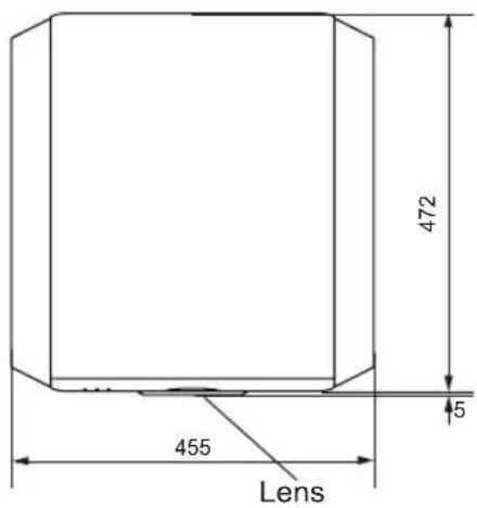
Bottom Surface
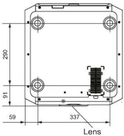
Front
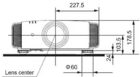
Back Surface
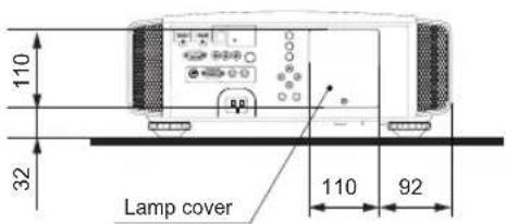
Connection terminal section of the illustration is RS50 RS60.
Index
3D
Shorthand for "Three-dimensional"
Operation Guide (Glossary) ...... Page 57
Connection by 3D SYNCHRO
terminal Page 28
3D format of [2-1] HDMI ...... Page 52
Picture Mode of [1] Picture Adjust ..... Page 45
Color Profile of [1] Picture Adjust ..... Page 45
Points of note ...... Page 4, 57
HDMI
Shorthand for "High-Definition Multimedia Interface"
Specifications ...... Page 74
Connection method ...... Page 26
[2-1] HDMI Page 51
(Note on length) Page 26
THX
THX Certification ...... Page 10
Picture Mode of [1] Picture Adjust ..... Page 45
Anamorphic Lens
Anamorphic of [3] Installation ...... Page 53
Color
Color Profile of [1] Picture Adjust ..... Page 45
Color temp. of [1] Picture Adjust..... Page 46
Color of [1] Picture Adjust ...... Page 46
Tint of [1] Picture Adjust ...... Page 46
[1-1] Color temp. Page 47
Color Space of [1-2] Advanced ...... Page 48
[1-2-2] Custom Gamma...... Page 49
[1-2-3] Color Management ...... Page 50
Screen Size
Distance Chart ...... Page 23
Aspect (Video) and aspect
(PC) of [2] Input Signal ...... Page 50
Zoom of [3-1] Lens Control ...... Page 53
Mask
Mask of [2] Input Signal ...... Page51
Screen Menu
Table Menu Structure ...... Page 37
[1] Picture Adjust ...... Page 37, 40
[2] Input Signal ...... Page 37, 41
[3] Installation ...... Page 38, 42
[4] Display Setup ...... Page 38
[5] Function ...... Page 39, 42
[6] Information ...... Page 39
Operating procedure ...... Page 44
Batteries
Types ...... Page 13
How to insert batteries ...... Page 19
Gamma
Glossary Page 56
Gamma of [1] Picture Adjust ...... Page 46
[1-2-2] Custom Gamma ...... Page 49
Spare parts
See "Filters" section
See "Lamp" section
Shift
Shift Amount ...... Page 21
Adjustment ...... Page 33
Zoom
Magnification ...... Page 74
Adjustment ...... Page 32
Installation
Angle ...... Page 21
Settings Page 50
Ceiling Mount Page 4,22
Caution Page 20
Settings Menu
Structure ...... Page 45
Menu operating method ...... Page 44
Projection Distance
Distance Chart ...... Page 23
Input Signal
PC signal support table ...... Page 24
[6] Information ...... Page 55
Noise
NR. of [1-2] Advanced Page 48
Filter
Inlet filter location ...... Page 14
Replacement Filter Number ...... Page 64
Cleaning and Replacement ...... Page 64
Message
Meaning ...... Page 68
Index (continued)
Lamp
Replacement Lamp Number ...... Page 60
Recommended use time ...... Page 60
Lamp time of [6] Information ...... Page 55
Replacement ...... Page 60
Lamp power of [1-2] Advanced ...... Page 49
Lamp reset of [5] Function ...... Page 55
How to reset the lamp time ...... Page 62, 63
Notes of Caution ...... Page 4
Remote control
Button placement ...... Page 19
Instructions ...... Page 23
See "Dry battery" section
Lens
[3-1] Lens Control ...... Page 53
Focus of [3-1] Lens Control ...... Page 53
Zoom of [3-1] Lens Control ...... Page 53
Shift of [3-1] Lens Control ...... Page 53
(Cleaning the lens) ...... Page 73
MANUEL D'INSTRUCTIONS
PROJECTEUR D-ILA
DLA-RS40
DLA-RS50
DLA-RS60
IMPORTANT INFORMATIONS
PORTABLE CART WARNING (symbol provided by RETAC)

S3126A
REPLACEMENT DU FUSIBLE:
Information for Users on Disposal of Old Equipment and Batteries


Products
Battery
[European Union only]
These symbols indicate that equipment with these symbols should not be disposed of as general household waste. If you want to dispose of the product or battery, please consider the collection systems or facilities for appropriate recycling.
Notice: The sign Pb below the symbol for batteries indicates that this battery contains lead.
DEUTSCH
La certification THX
Accessoires/Accessories
facultatifs....13
Vérifier les accessoires .... 13
Accessoires facultatifs.... 13
Types of possible input signals (PC compatible)....24
natural_image
Simple line drawing of a door with a speaker and directional arrow, no text or symbols present②
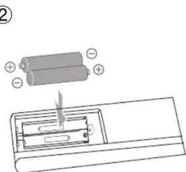
③
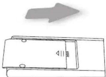
natural_image
Simple line drawing of a door with a speaker and directional arrow (no text or symbols)natural_image
Diagram of optical system with lenses and detectors, no text or symbols presentnatural_image
Technical line drawing of a mechanical assembly with three components (no text or symbols)Face inférieure
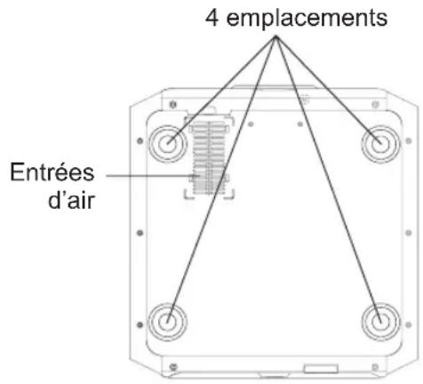
Types of possible input signals (PC compatible)
HDMI
| N°. | Désignation | Résolution | fh[kHz] | fv[Hz] | Fréquence CLK [MHz] | Nombre total de points [dot] | Nombre total de lignes [line] | Nombre de points effectifs [dot] | Nombre de lignes effectives [line] |
| 1 | VGA 60 640 | X 480 31,500 | 60,000 25, | 200 800 5 | 25 640 480 | ||||
| 2 | VGA 59,94 640 | X 480 31,469 | 59,940 25 | 175 800 | 525 640 480 | ||||
| 3 | SVGA 60 800 | X 600 37,879 | 60,317 40 | 000 1,056 | 628 800 600 | ||||
| 4 | XGA 60 1024 | X 768 48,363 | 60,004 65 | 000 1,344 | 806 | 1,024 | 768 | ||
| 5 | WXGA 60 | 1280 X 768 | 47,760 | 60,000 | 79,998 | 1,675 | 796 | 1,280 | 768 |
| 6 | WXGA +60 | 1440 X 900 | 55,919 | 59,999 | 106,470 | 1,904 | 932 | 1,440 | 900 |
| 7 | SXGA 60 | 1280 X 1024 | 63,981 | 60,020 | 108,000 | 1,688 | 1,066 | 1,280 | 1,024 |
| 8 | WSXGA +60 | 1680 X 1050 | 65,222 | 60,002 | 147,140 | 2,256 | 1,087 | 1,680 | 1,050 |
| 9 | WUXGA 60 | 1920 X 1200 | 74,038 | 59,95 | 154,000 | 2,080 | 1,235 | 1,920 | 1,200 |
PC (D-sub 3-lines 15 pins)
| N°. | Désignation | Résolution | fh [kHz] | fv [Hz] | Fréquence CLK [MHz] | Nombre total de points [dot] | Nombre total de lignes [line] | Nombre de points effectifs [dot] | Nombre de lignes effectives [line] |
| 1 | VGA 60 640 | X 480 31,500 | 60,000 | 25,175 | 800 525 640 | 480 | |||
| 2 | VGA 72 640 | X 480 37,900 | 72,000 | 31,500 | 832 520 640 | 480 | |||
| 3 | VGA 75 640 | X 480 37,500 | 75,000 | 31,500 | 840 500 640 | 480 | |||
| 4 | VGA 85 640 | X 480 43,300 | 85,000 | 36,000 | 832 509 640 | 480 | |||
| 5 | SVGA 56 | 800 X 600 | 35,200 | 56,000 | 36,000 | 1024 | 625 | 800 | 600 |
| 6 | SVGA 60 | 800 X 600 | 37,900 | 60,000 | 40,000 | 1056 | 628 | 800 | 600 |
| 7 | SVGA 72 | 800 X 600 | 48,100 | 72,000 | 50,000 | 1040 | 666 | 800 | 600 |
| 8 | SVGA 75 | 800 X 600 | 46,900 | 75,000 | 49,500 | 1056 | 625 | 800 | 600 |
| 9 | SVGA 85 | 800 X 600 | 53,700 | 85,000 | 56,250 | 1048 | 631 | 800 | 600 |
| 10 | XGA 60 | 1024 X 768 | 48,400 | 60,000 | 65,000 | 1344 | 806 | 1024 | 768 |
| 11 | XGA 70 | 1024 X 768 | 56,500 | 70,000 | 75,000 | 1328 | 806 | 1024 | 768 |
| 12 | XGA 75 | 1024 X 768 | 60,000 | 75,000 | 75,750 | 1312 | 800 | 1024 | 768 |
| 13 | XGA 85 | 1024 X 768 | 68,700 | 85,000 | 94,500 | 1376 | 808 | 1024 | 768 |
| 14 | WXGA 60 | 1280 X 768 | 47,760 | 60,000 | 79,998 | 1675 | 796 | 1280 | 768 |
| 15 | WXGA+ 60 | 1440 X 900 | 55,919 | 59,999 | 106,470 | 1904 | 932 | 1440 | 900 |
| 16 | SXGA 60 | 1280 X 1024 | 64,000 | 60,000 | 108,000 | 1688 | 1066 | 1280 | 1024 |
| 17 | SXGA+ 60 | 1400 X 1050 | 63,981 | 60,020 | 108,000 | 1688 | 1066 | 1400 | 1050 |
| 18 | WSXGA+ 60 | 1680 X 1050 | 65,222 | 60,002 | 147,140 | 2256 | 1087 | 1680 | 1050 |
| 19 | 1920x1080 60 | 1920 X 1080 | 67,500 | 60,00 | 148,500 | 2200 | 1125 | 1920 | 1080 |
| 20 | MAC13" | 640 X 480 | 35,000 | 66,667 | 30,240 | 864 | 525 | 640 | 480 |
| 21 | MAC16" | 832 X 624 | 49,107 | 75,087 | 55,000 | 1120 | 654 | 832 | 624 |
| 22 | MAC19" | 1024 X 768 | 60,241 | 74,927 | 80,000 | 1328 | 804 | 1024 | 768 |
natural_image
Illustration of three computer devices: desktop tower, laptop, and monitor (no text or symbols)PC
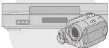
natural_image
Illustration of a video camera with an external screen (no text or symbols visible)natural_image
Red panda resting on ground near a tree (no text or symbols visible)
natural_image
Black-and-white photo of a red panda resting in a forest, no visible text or symbols3 Pour terminer

flowchart
graph LR
    A["Group Comparison"] --> B["Group Comparison"]
    B --> C["Group Comparison"]
    C --> D["Group Comparison"]
natural_image
Line drawing of a computer monitor with ports and a cable, showing an arrow indicating motion (no text or symbols present)natural_image
Diagram of a computer monitor internal structure with an airplane icon pointing to the screen (no text or symbols present)natural_image
Diagram of a computer tower with an open panel and internal components, showing a close-up view (no text or symbols)Poignée
natural_image
Diagram of a device interior showing internal components and a curved arrow indicating rotation (no text or symbols present)natural_image
Line drawing of a computer monitor with ports and a cable connector (no text or symbols)
AVERTISSEMENT
Do not place the removed lamp unit at locations that is reachable by children or near combustible items
Dispose used lamp units in the same way as fluorescent lamps Follow your local community rules for disposal.
Remplacement de la lampe (Suite)
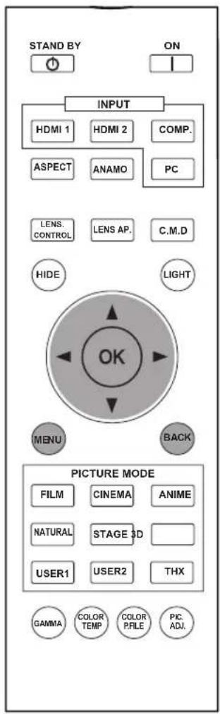
RS50 RS60

AVERTISSEMENT
natural_image
Technical diagram of a mechanical component with no visible text or symbolsnatural_image
Line drawing of hands handling a tray with liquid, no text or symbols present
natural_image
Illustration of a hand holding a device with a black X symbol (no text or symbols present)natural_image
Diagram of a mechanical device with labeled components and directional arrows (no readable text or symbols)Interface RS-232C (Suite)
Interface RS-232C (Suite)
Exemples de communication RS-232C
Sigle de "High-Definition Multimedia Interface":
Adjustment ...... Page 32
Installation
Angle......Page 21
Réglages...... Page 50
PORTABLE CART WARNING (symbol provided by RETAC)
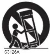
REMLACEMENT DU FUSIBLE:
Information for Users on Disposal of Old Equipment and Batteries


Products

Battery
[European Union only]
These symbols indicate that equipment with these symbols should not be disposed of as general household waste. If you want to dispose of the product or battery, please consider the collection systems or facilities for appropriate recycling.
Notice: The sign Pb below the symbol for batteries indicates that this battery contains lead.
DEUTSCH
natural_image
Simple line drawing of a door with a speaker and directional arrow (no text or symbols)②
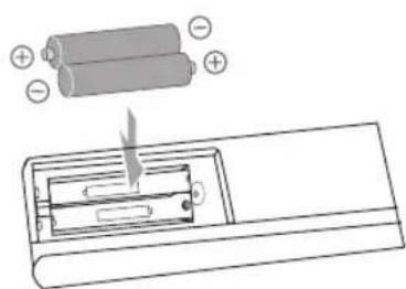
③
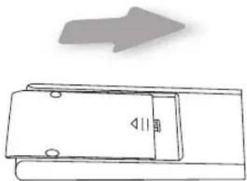
natural_image
Simple line drawing of a door with an arrow pointing upward (no text or symbols)natural_image
Diagram of light ray paths through a lens system with two rectangular objects (no text or symbols)natural_image
Technical line drawing of a mechanical assembly with three components (no text or symbols)Superficie inferior
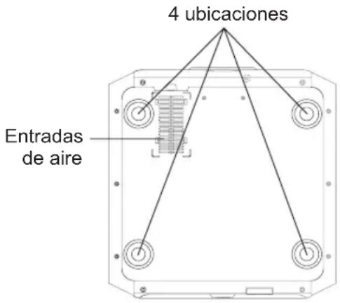
natural_image
Black-and-white photo of a red panda resting on grass near a tree (no text or symbols visible)natural_image
Black-and-white photo of two red pandas resting in a natural enclosure with trees and grass (no text or symbols visible)3 Para terminar

flowchart
graph LR
    A["Person with face"] --> B["Person with face"]
    B --> C["Person with face"]
[1-2-2] Personal Gamma
In most cases, 3D images taken or produced are horizontally arranged respectively. If these images were not horizontally arranged for left and right eye movement when watching, the brain could not perceive a stereoscopic image, but would still recognize a double image. As such video images can cause 3D sickness, please do not hold the 3D glasses slanted relative to the video images.
natural_image
Line drawing of a computer monitor with ports and a dashed arrow indicating motion (no text or symbols)natural_image
Diagram of a computer monitor internal structure with an airplane icon pointing to the screen (no text or symbols present)natural_image
Diagram of a device interior showing internal components and a directional arrow indicating rotation (no text or symbols present)natural_image
Diagram of a projector unit with a curved arrow indicating direction (no text or symbols present)
ADVERTENCIA

ADVERTENCIA
natural_image
Technical diagram of a mechanical device with labeled components and an arrow indicating direction (no text or symbols present)Levante mie ntras empuja la pinza
2 Limpie el filtro
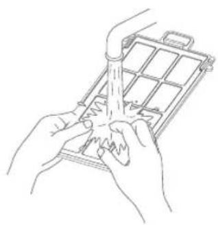
natural_image
Line drawing of hands holding a tray with a handle, no text or symbols present