
DLA-HD10KU - Projector JVC - Free user manual and instructions
Find the device manual for free DLA-HD10KU JVC in PDF.
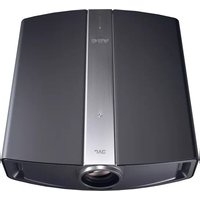


| Product Type | Video Projector |
| Brand | JVC |
| Model | DLA-HD10KU |
| Display Technology | D-ILA (Direct Drive Image Light Amplifier) |
| Native Resolution | 1920 x 1080 pixels (Full HD) |
| Brightness | 1000 ANSI Lumens |
| Contrast Ratio | 15000:1 |
| Lamp Type | 200W UHP (Ultra High Performance) |
| Lamp Life | 3000 hours (Normal Mode) |
| Projection Lens | 2x motorized zoom and focus |
| Input Terminals | HDMI, Component, S-Video, Composite, RGB |
| Video Compatibility | NTSC, PAL, SECAM |
| Horizontal Frequency | 15 - 90 kHz |
| Vertical Frequency | 50 - 120 Hz |
| Noise Level | 25 dB (Eco Mode) |
| Power Consumption | 300 W (Maximum), 1 W (Standby) |
| Dimensions (W x H x D) | 455 mm x 145 mm x 360 mm |
| Weight | 10.5 kg |
| Installation | Ceiling Mount, Table Top |
| Maintenance | Air filter cleaning, lamp replacement |
| Safety Features | Overheat protection, auto power off |
Frequently Asked Questions - DLA-HD10KU JVC
User questions about DLA-HD10KU JVC
0 question about this device. Answer the ones you know or ask your own.
Ask a new question about this device
Download the instructions for your Projector in PDF format for free! Find your manual DLA-HD10KU - JVC and take your electronic device back in hand. On this page are published all the documents necessary for the use of your device. DLA-HD10KU by JVC.
USER MANUAL DLA-HD10KU JVC
INSTRUCTIONS MANUEL D'INSTRUCTIONS

For Customer use :
Enter below the serial No. which is located on the side panel of the cabinet. Retain this information for future reference.
Model No. DLA-HD10KU/DLA-HD10KSU
Serial No.
Language for Manuals of Products using HID Lamps (that contains mercury)
This product has a High Intensity Discharge (HID) lamp that contains a small amount of mercury. It also contains lead in some components.
Disposal of these materials may be regulated in your community due to environmental considerations. For disposal or recycling information please contact your local authorities, or the Electronics Industries Alliance: http://www.eiae.org.
WARNING:
TO PREVENT FIRE OR SHOCK HAZARDS, DO NOT EXPOSE THIS APPLIANCE TO RAIN OR MOISTURE.
WARNING:
THIS APPARATUS MUST BE EARTHED.
CAUTION:
To reduce the risk of electric shock, do not remove cover. Refer servicing to qualified service personnel.
This projector is equipped with a 3-blade grounding type plug to satisfy FCC rule. If you are unable to insert the plug into the outlet, contact your electrician.
FCC INFORMATION (U.S.A. only)
CAUTION:
Changes or modification not approved by JVC could void the user's authority to operate the equipment.
NOTE:
This equipment has been tested and found to comply with the limits for Class B digital devices, pursuant to Part 15 of the FCC Rules. These limits are designed to provide reasonable protection against harmful interference in a residential installation. This equipment generates, uses, and can radiate radio frequency energy and, if not installed and used in accordance with the instructions, may cause harmful interference to radio communications. However, there is no guarantee that interference will not occur in a particular installation. If this equipment does cause harmful interference to radio or television reception, which can be determined by turning the equipment off and on, the user is encourage to try to correct the interference by one or more of the following measures:
●Reorient or relocate the receiving antenna.
- Increase the separation between the equipment and receiver.
- Connect the equipment into an outlet on a circuit different from that to which the receiver is connected.
- Consult the dealer or an experienced radio/TV technician for help.
MACHINE NOISE INFORMATION (Germany only)
Changes Machine Noise Information Ordinance 3. GSGV, January 18, 1991: The sound pressure level at the operator position is equal or less than 70 dB (A) according to ISO 7779.
About burning-in of the D-ILA device
Do not allow the same still picture to be projected for a long time or an abnormally bright video picture to be projected. Do not project video images with high-intensity or high contrast on a screen. The video image could be burnt into the D-ILA device.
Use special care when projecting video games or computer program images. There is no problem with ordinary video-cassette playback images.
About the installation place
Do not install the projector in a place that cannot support its weight securely.
If the installation place is not sturdy enough, the projector could fall or overturn, possibly causing personal injury.
IMPORTANT SAFEGUARDS
Electrical energy can perform many useful functions. This unit has been engineered and manufactured to assure your personal safety. But IMPROPER USE CAN RESULT IN POTENTIAL ELECTRICAL SHOCK OR FIRE HAZARD. In order not to defeat the safeguards incorporated into this product, observe the following basic rules for its installation, use and service. Please read these Important Safeguards carefully before use.
- All the safety and operating instructions should be read before the product is operated.
–The safety and operating instructions should be retained for future reference. - All warnings on the product and in the operating instructions should be adhered to.
-All operating instructions should be followed.
—Place the projector near a wall outlet where the plug can be easily unplugged.
—Unplug this product from the wall outlet before cleaning. Do not use liquid cleaners or aerosol cleaners. Use a damp cloth for cleaning. - Do not use attachments not recommended by the product manufacturer as they may be hazardous.
- Do not use this product near water. Do not use immediately after moving from a low temperature to high temperature, as this causes condensation, which may result in fire, electric shock, or other hazards.
- Do not place this product on an unstable cart, stand, or table. The product may fall, causing serious injury to a child or adult, and serious damage to the product. The product should be mounted according to the manufacturer's instructions, and should use a mount recommended by the manufacturer.
- When the product is used on a cart, care should be taken to avoid quick stops, excessive force, and uneven surfaces which may cause the product and cart to overturn, damaging equipment or causing possible injury to the operator.
PORTABLE CART WARNING
(symbol provided by RETAC)

S3126A
- Slots and openings in the cabinet are provided for ventilation. These ensure reliable operation of the product and protect it from overheating. These openings must not be blocked or covered. (The openings should never be blocked by placing the product on bed, sofa, rug, or similar surface. It should not be placed in a built-in installation such as a bookcase or rack unless proper ventilation is provided and the manufacturer's instructions have been adhered to.) For proper ventilation, separate the product from other equipment, which may prevent ventilation and keep a distance of more than 11-7/8" (30 cm).
- This product should be operated only with the type of power source indicated on the label. If you are not sure of the type of power supply to your home, consult your product dealer or local power company.
- This product is equipped with a three-wire plug. This plug will fit only into a grounded power outlet. If you are unable to insert the plug into the outlet, contact your electrician to install the proper outlet. Do not defeat the safety purpose of the grounded plug.
–Power-supply cords should be routed so that they are not likely to be walked on or pinched by items placed upon or against them. Pay particular attention to cords at doors, plugs, receptacles, and the point where they exit from the product.
-For added protection of this product during a lightning storm, or when it is left unattended and unused for long periods of time, unplug it from the wall outlet and disconnect the cable system. This will prevent damage to the product due to lightning and power line surges.
- Do not overload wall outlets, extension cords, or convenience receptacles on other equipment as this can result in a risk of fire or electric shock.
—Never push objects of any kind into this product through openings as they may touch dangerous voltage points or short out parts that could result in a fire or electric shock. Never spill liquid of any kind on the product.
- Do not attempt to service this product yourself as opening or removing covers may expose you to dangerous voltages and other hazards. Refer all service to qualified service personnel.
- Unplug this product from the wall outlet and refer service to qualified service personnel under the following conditions:
a) When the power supply cord or plug is damaged.
b) If liquid has been spilled, or objects have fallen on the product.
c) If the product has been exposed to rain or water.
d) If the product does not operate normally by following the operating instructions. Adjust only those controls that are covered by the Operation Manual, as an improper adjustment of controls may result in damage and will often require extensive work by a qualified technician to restore the product to normal operation.
e) If the product has been dropped or damaged in any way.
f) When the product exhibits a distinct change in performance - this indicates a need for service.
- When replacement parts are required, be sure the service technician has used replacement parts specified by the manufacturer or with same characteristics as the original part. Unauthorized substitutions may result in fire, electric shock, or other hazards.
Upon completion of any service or repairs to this product, ask the service technician to perform safety checks to determine that the product is in proper operating condition.
- The product should be placed more than one foot away from heat sources such as radiators, heat registers, stoves, and other products (including amplifiers) that produce heat.
- When connecting other products such as VCR's, and personal computers, you should turn off the power of this product for protection against electric shock.
-Do not place combustibles behind the cooling fan. For example, cloth, paper, matches, aerosol cans or gas lighters that present special hazards when over heated.
- Do not look into the projection lens while the illumination lamp is turned on. Exposure of your eyes to the strong light can result in impaired eyesight.
—Do not look into the inside of this unit through vents (ventilation holes), etc. Do not look at the illumination lamp directly by opening the cabinet while the illumination lamp is turned on. The illumination lamp also contains ultraviolet rays and the light is so powerful that your eyesight can be impaired.
- Do not drop, hit, or damage the light-source lamp (lamp unit) in any way. It may cause the light-source lamp to break and lead to injuries. Do not use a damaged light source lamp. If the light-source lamp is broken, ask your dealer to repair it. Fragments from a broken light-source lamp may cause injuries.
—The light-source lamp used in this projector is a high pressure mercury lamp. Be careful when disposing of the light-source lamp. If anything is unclear, please consult your dealer.
—Do not ceiling-mount the projector to a place which tends to vibrate; otherwise, the attaching fixture of the projector could be broken by the vibration, possibly causing it to fall or overturn, which could lead to personal injury.
Use only the accessory cord designed for this product to prevent shock.
The power supply voltage rating of this product is AC120 V, AC100 V – AC240 V, the power cord attached conforms to the following power supply voltage. Use only the power cord designated by our dealer to ensure Safety and EMC.
When it is used by other power supply voltage, power cable must be changed.
Ensure that the power cable used for the projector is the correct type for the AC outlet in your country. Consult your product dealer.
Power cord

For United Kingdom For European continent countries
Power cord

Power supply voltage: AC 120 V
*DO NOT allow any unqualified person to install the unit.
Be sure to ask your dealer to install the unit (e.g. attaching it to the ceiling) since special technical knowledge and skills are required for installation. If installation is performed by an unqualified person, it may cause personal injury or electrical shock.
POWER CONNECTION
WARNING:
Do not cut off the main plug from this equipment.
If the plug fitted is not suitable for the power points in your home or the cable is too short to reach a power point, then obtain an appropriate safety approved extension lead or adapter or consult your dealer.
If nonetheless the mains plug is cut off, remove the fuse and dispose of the plug immediately, to avoid a possible shock hazard by inadvertent connection to the main supply. If a new main plug has to be fitted, then follow the instruction given below:
WARNING:
THIS APPARATUS MUST BE EARTHED. IMPORTANT:
The wires in the mains lead on this product are colored in accordance with the following cord:
Green-and-yellow : Earth
Blue : Neutral
Brown : Live
As these colors may not correspond with the colored making identifying the terminals in your plug, proceed as follows:
The wire which is colored green-and-yellow must be connected to the terminal which is marked ⏻ with the letter E or the safety earth or colored green or green-and-yellow.
The wire which is colored blue must be connected to the terminal which is marked with the letter N or colored black.
The wire which is colored brown must be connected to the terminal which is marked with the letter L or colored red.
When replacing the fuse, be sure to use only a correctly rated approved type, re-fit the fuse cover.
IF IN DOUBT — CONSULT A COMPETENT ELECTRICIAN.
How To Replace The Fuse
Open the fuse compartment with the blade screwdriver, and replace the fuse.
(* An example is shown in the illustration below.)
POWER CONNECTION (United Kingdom only)
WARNING:
Do not cut off the main plug from this equipment.
If the plug fitted is not suitable for the power points in your home or the cable is too short to reach a power point, then obtain an appropriate safety approved extension lead or adapter or consult your dealer.
If nonetheless the mains plug is cut off, remove the fuse and dispose of the plug immediately, to avoid a possible shock hazard by inadvertent connection to the main supply.
If a new main plug has to be fitted, then follow the instruction given below:
WARNING:
THIS APPARATUS MUST BE EARTHED.
IMPORTANT:
The wires in the mains lead on this product are coloured in accordance with the following cord:
Green-and-yellow : Earth
As these colours may not correspond with the coloured making identifying the terminals in your plug, proceed as follows:
The wire which is coloured green-and-yellow must be connected to the terminal which is marked ⏻ with the letter E or the safety earth or coloured green or green-and-yellow.
The wire which is coloured blue must be connected to the terminal which is marked with the letter N or coloured black.
The wire which is coloured brown must be connected to the terminal which is marked with the letter L or coloured red.
When replacing the fuse, be sure to use only a correctly rated approved type, re-fit the fuse cover.
IF IN DOUBT — CONSULT A COMPETENT ELECTRICIAN.
How To Replace The Fuse
Open the fuse compartment with the blade screwdriver, and replace the fuse.
(* An example is shown in the illustration below.)

ENGLISH
Information for Users on Disposal of Old Equipment
Attention:
This symbol is only valid in the European Union.

[European Union]
This symbol indicates that the electrical and electronic equipment should not be disposed as general household waste at its end-of-life. Instead, the product should be handed over to the applicable collection point for the recycling of electrical and electronic equipment for proper treatment, recovery and recycling in accordance with your national legislation.
By disposing of this product correctly, you will help to conserve natural resources and will help prevent potential negative effects on the environment and human health which could otherwise be caused by inappropriate waste handling of this product. For more information about collection point and recycling of this product, please contact your local municipal office, your household waste disposal service or the shop where you purchased the product. Penalties may be applicable for incorrect disposal of this waste, in accordance with national legislation.
(Business users)
If you wish to dispose of this product, please visit our web page www.jvc-europe.com to obtain information about the take-back of the product.
[Other Countries outside the European Union]
If you wish to dispose of this product, please do so in accordance with applicable national legislation or other rules in your country for the treatment of old electrical and electronic equipment.
DEUTSCH
About Burning-in of D-ILA Device
■Do not allow the same still picture to be projected for a long time or an abnormally bright video image to be projected
Do not project still images, etc. with a high intensity or high contrast on the screen for a long time. This video image could be burnt into this D-ILA device.
Pay special attention when projecting video games and computer program images.
There is no problem with ordinary video cassette playback images.
Viewing Conditions (Brightness of Room)
■Brightness of the room
Avoid direct exposure of screen to direct sunlight and illumination. Block light using a curtain. Images can be well projected by darkening the brightness of the room.
■Do not view screen for prolonged hours
Looking at the screen continually for a prolonged time will cause your eyes to get tired. Allow your eyes to rest at intervals.
■Do not use this unit when image flickers
This may cause your eyesight to deteriorate.
Environment of Use
■Do not use this unit in rooms with cigarette smoke or oily smoke
Do not use this unit in rooms with cigarette smoke or oily smoke. This may cause the unit to malfunction.
■When mounting this unit to the ceiling
Check temperature around the unit.
When a heater is in use, the ceiling may reach a temperature higher than anticipated, hence leading to malfunction of the unit.
Maintenance Procedures
■Clean dirt on the cabinet
with a soft cloth. In case of heavy soiling, soak a cloth in neutral detergent diluted with water, wring dry and wipe, followed by wiping again using a dry cloth.
■Pay attention to the following as the cabinet may deteriorate in condition, get damaged or paint may come off.
- Do not wipe with a stiff cloth
- Do not wipe with force
- Do not wipe with thinner or benzene
- Do not spray volatile chemicals like insecticide
- Do not allow prolonged contact with rubber or plastic products
■Dirt on the lens
shall be cleaned using commercial blowers or lens cleaning papers (for cleaning glasses and cameras).
Do not use fluid-type cleaning agents. This may lead to peeling of the surface coating film.
Lens surface is fragile. Avoid rubbing it hard or knocking it.
Standard for gauging replacement time of components
There are replacement components required for maintenance of the functions of this product such as optical components, cooling fan and filters. Life span of components varies considerably with the frequency of use and environment in which they are used. For replacement of components (except filters), please consult your authorized dealer.
SAFETY PRECAUTIONS ....2
Caution 9
Accessories ....10
Accessories 10
Optional Accessories 10
Controls and Features ....11
Front Side/Top Surface/Bottom Surface 11
Rear Side/Right Side 12
Control Panel 13
Indicators 14
Indicator Display 15
Remote Control 16
Loading Batteries into the Remote Control ..... 17
Installing the Projector ....18
Precautions for Installation 18
Mounting this Unit 19
Projector and Screen Installation 20
Screen Size and Projection Distance 21
Lens Shift Setting 22
Effective Range of Remote Control Unit 23
Connecting to Various Devices ....24
Connecting to Devices 24
Connecting the Power Cord (Supplied) 25
Basic Operation Procedures 26
Adjustments and Settings Using Menus 28
Menu Structure ......28
Menu Operation Buttons ......29
Procedures for Menu Operation ....30
Menu Configuration ....31
Screen Masking 33
Picture Shift Setting 34
Replacing the Lamp 35
Light-source Lamp and Lamp Usage Time ....35
Procedure for Lamp Replacement ....36
Resetting Lamp Time 38
Cleaning and Replacing the Filter 39
What to do when these messages are displayed 40
Warning Indication 41
Troubleshooting 42
Terminal Description 44
Pin Arrangement ....44
RS-232C External Control 45
Specifications 47
Accessories
Accessories
The following accessories are packed together with this unit. Please confirm all items.
If any item is missing, please contact your dealer.
Instructions....x 1
Guarantee....x 1
Power Cord....x 1
Remote Control (RM-MH10KG)....x 1
AAA size Batteries (for operation confirmation) ......x 2
Optional Accessories
Please seek your authorized dealer for details.
■Replacement Lamp : BHL5008-S (Lamp Unit)
■Replacement Filter : LC32058-002A (Inner Filter)
Front Side/Top Surface/Bottom Surface


1 Indicator
Please refer to "Indicators" (Page 14) for details.
2 Air Inlets (2 in front and 1 at bottom surface)
The air inlets absorb air to cool the interior of the unit. Do not block or allow warm air to blow into them. This may cause the unit to malfunction.
3 Power Zoom Lens
DLA-HD10KU/E :1.9x power zoom lens
DLA-HD10KSU/E:1.4x power zoom lens
- Before projection, remove the lens cap. (Page 26)
4 Remote Sensor (Front)
When operating with the remote control, aim it towards the sensor. (Page 23)
- A remote sensor is also located on the rear of the unit.
5 Lens Cap
●Fit the cap on the lens when this unit is not in use to prevent the lens from becoming dirty. (Page 26)
6 Lens Shift Cover
Remove this cover when using the Lens Shift feature for shifting the projecting position in the vertical direction. (Page 22)
7 Foot
It is set at the lowest position when shipped from the factory. This unit does not come with a function to adjust the gradient.
8 Filter
Cleans air drawn in from the air inlet. Please clean this filter regularly. (Page 39)
Rear Side/Right Side

1 Control Panel Cover
Remove this cover when operating this unit or when replacing the lamp unit.
- Unlock the cover, followed by sliding it downwards to remove it.
- Please refer to page 13 for details on the control panel.
Handling the Control Panel Cover
●The gap between this unit and the control panel cover is narrow. Be careful not to stick your finger into the gap between this unit and the control panel cover.
- Be careful of the protrusions and corners of components to avoid injury.
●After attaching the control panel cover, check that the lock is fastened. The control panel cover may drop and cause injury.
2 Exhaust Vent
Warm air is expelled through this vent to keep the system cool. Do not block the exhaust vents. This may cause the unit to malfunction.
3 AC Power Input Terminal
This is the AC power input terminal. Connect the supplied cord to this terminal. (Page 25)
4 Remote Sensor (Rear)
When operating with the remote control, aim it towards the sensor. (Page 23)
●A remote sensor is also located at the front of the unit.
5 SCREEN TRIGGER Terminal
This terminal is used for controlling the SCREEN TRIGGER-compatible elevating screen. An output at DC +12 V/100 mA (max.) is produced when the power is on.
- Consult a qualified technician for a connection with the screen.
6 [SERVICE] Terminal
This terminal is intended for servicing purposes. Do not use it. Using it may give rise to error and malfunction of the unit.
7 [RS-232C] Terminal (D-sub 9 Pin)
This is the RS-232C interface-specific terminal. This unit can be controlled by a computer connected externally. (Pages 24, 45)
- For details, please check with your authorized dealer.
8[DVI] Terminal (DVI-D 24 Pin)
This is an input terminal for video signals. Video signals that can be input are 1080/50p and 1080/60p signals. (Page 24)
Control Panel

1[Rx/Tx] Indicator
This indicator lights up during communication with the computer using the RS-232C terminal. (Page 15)
[Rx] : Lights up when this unit is receiving RS-232C data.
[Tx] : Lights up when this unit is sending RS-232C data.
2 [MENU] Button
Press this button to display the menu. Pressing this button when the menu is displayed clears the menu. (Pages 29, 30)
3 [EXIT] Button
Press this button to return to the previous hierarchical menu (for example, to return from submenu to main menu). Pressing this button when the main menu is displayed clears the menu. (Pages 29, 30)
4 [ZOOM T/W] Button
Press this button to change the size of the projected image. (Page 26)
5 [FOCUS +/-] Button
Press this button to adjust focus of the projected image. (Page 27)
6 Cursor [▲/▼/◄/►] Buttons
Use these buttons when adjusting the menu items. (Pages 29, 30)
7[ENTER] Button
Press this button to show the next hierarchical menu (for example, to enter submenu from main menu). It is also used when "ENTER" is displayed against a selection item on the menu screen. (Pages 29, 30)
8[OPERATE ON] Button
When this unit is in the standby mode, pressing this button for more than 1 second will turn the unit on and cause the [OPERATE] indicator to light up. (Page 26)
9[OPERATE OFF] Button
When this unit is operating (projecting), pressing this button for more than 1 second switches the unit to the cool down mode, which will automatically switch to the standby mode after about 60 seconds. (Page 27)
- The [OPERATE OFF] button will not work within approximately 1 minute after the light source has been turned on. Start operation only after 1 minute's time.
10[HIDE] Button
Use this button to temporarily clear the video image. Press again to resume. (Page 27)
Indicators

1 [STAND BY] Indicator
Light on : When in the standby mode. (Pages 15, 26)
Blinking : When in the cool down mode. (Pages 15, 27)
2 [OPERATE] Indicator
Light on : When this unit is currently operating (projecting). (Pages 15, 26)
3 [LAMP] Button
Light on: When the lamp needs to be replaced soon or immediately. (Page 15)
When the lamp cover is removed. (Page 41)
When the lamp does not light up and the unit is unable to project, or when the lamp goes off during projection. (Page 41)
4 [TEMP] Indicator
Light on: When the internal temperature of the unit is abnormally high. (Page 41)
Blinking: When the lamp needs to be replaced soon or immediately. (Page 15)
When an abnormality has occurred in this unit. (Page 41)
5 [FAN] Indicator
Light on : When the internal fan abnormally stopped running. (Page 41)
Blinking: When the lamp has reached the end of its life and it is time to replace the lamp. ( page 15)
When an abnormality has occurred in this unit. (Page 41)
6 [HIDE] Indicator
Light on : When the video image is temporarily cleared upon pressing the [HIDE] button. (Pages 15, 27)
Blinking : When an abnormality has occurred in this unit. (Page 41)
Indicator Display
This unit displays operational states using different combination of indicators.
- Please refer to page 35 for explanations on warning indication for *2.
- Please refer to page 41 for indications when an abnormality occurs in this unit.
Indicator Display on the Top Surface
| Indicator | Description | |||||
| STAND BY OPERATE LAMP TEMP FAN HIDE | ||||||
| Light On — | — | — | — | — | — | Unit is in standby mode |
| — | Light On | — | — | — | — | Unit is in operate mode (during projection) |
| — | Light On | — | — | — | Light On | When the video image is temporarily cleared upon pressing the [HIDE] button during projection |
| Blinking | — | — | — | — | *1 Unit is in cool down mode (when cooling lamp) | |
| — | — | Light On | Blinking | — | — | *2 About time to replace lamp (Lamp usage time has exceeded 1900 hours) |
| — | — | Light On | — | Blinking | — | *2 Lamp life has expired (Lamp usage time has exceeded 2000 hours) |
| — | — | Light On | Blinking | Blinking | — | *2 When unit is forced to switch to cool down mode Time to replace lamp (Lamp usage time has exceeded 2010 hours) |
Indicator Display on the Control Panel
| Indicator | Description | |
| Rx | Tx | |
| Light On | — | When this unit is receiving RS-232C data |
| — | Light On | When this unit is sending RS-232C data |
*1 About Cool Down Mode
After projection, the heated lamp will go through a 60-second cool-down process known as the cool down mode. This function is to prevent damage and deformation that heat from the heated lamp may cause to the internal components of this unit. It also prevents lamp breakage and shortened lamp life.
The cool down mode is indicated by the blinking [STAND BY] indicator. When in the cool down mode, the [OPERATE ON] button will be disabled.
After the cool down process is completed, the unit will automatically switch to the standby mode.
CAUTION:
When in the cool down mode, do not pull out the plug from the power outlet. Also, do not block the air inlets/exhaust vents by standing this unit on its end or laying it on its side.
Remote Control
![graph TD 1["1"] --> OPERATE["OPERATE"] 2["2"] --> ON["ON"] 3["3"] --> CHP["CHP"] 4["4"] --> LIGHT["LIGHT"] 5["5"] --> MENUEXIT["MENUEXIT"] 6["6"] --> ENTER["ENTER"] 7["7"] --> PRESET["PRESET"] 8["8"] --> T["ZOOM"] 8 --> W["W"] 9["9"] --> OFF["OFF"] 10["10"] --> TEST["TEST"] 11["11"] --> OPEN["OPEN"]…](/content/2026/08/1575066/images/868a18a926480fc775a8edf46bfaa351f858901c0e1bc1d0420fd900c0194991.jpg)
1 Remote Control's Signal Transmitter
Page 23
2[OPERATE ON] Button
When this unit is in the standby mode, pressing this button for more than 1 second will turn the unit on and cause the [OPERATE] indicator to light up. (Page 26)
3 [LIGHT] Button
Lights up illumination (light) of the remote control buttons for about 10 seconds.
4[CHP] (Cross Hatch Pattern) Button
Press this button to adjust the focus. Pressing this button projects a green cross hatch signal for adjustment.
- Press the [EXIT] button to return to the original image.
5 [MENU] Button
Press this button to display the menu. Pressing this button when the menu is displayed clears the menu. (Pages 29, 30)
6 Cursor [▲ / ▼ / ◀ / ▶] Buttons
Use these buttons when adjusting the menu items. (Pages 29, 30)
7 [PRESET] Button
Use this button to reset the values to factory settings when items in the menu are selected.
8[ZOOM T/W] Button
Press this button to change the size of the projected image. (Page 26)
9[OPERATE OFF] Button
When this unit is operating (projecting), pressing this button for more than 1 second switches the unit to the cool down mode, which will automatically switch to the standby mode after about 60 seconds. (Page 27)
- The [OPERATE OFF] button will not work within approximately 1 minute after the light source has been turned on. Start operation only after 1 minute's time.
10[TEST] Button
Press this when adjusting focus, screen size or picture quality. Press the button to switch to the test pattern image for adjustment.
- Alter the test pattern with the [TEST] button.
- Press the [EXIT] button to return to the original image.
11[EXIT] Button
Press this button to return to the previous hierarchical menu (for example, to return from submenu to main menu). Pressing this button when the main menu is displayed clears the menu. (Pages 29, 30)
12[ENTER] Button
Press this button to show the next hierarchical menu (for example, to enter submenu from main menu). It is also used when "ENTER" is displayed against a selection item on the menu screen. (Pages 29, 30)
13[HIDE] Button
Press this button to temporarily clear the video image. Press again to resume. (Page 27)
14 [FOCUS +/-] Button
Use this button to adjust focus of the projected image. ( page 27)
Loading Batteries into the Remote Control
Load batteries into the remote control. If the remote control starts to function erratically, replace the batteries.
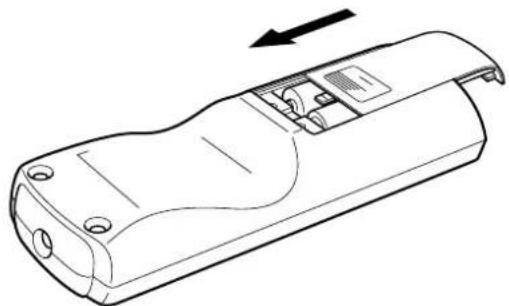
1Open the back cover
Press the back cover slightly and slide it in the direction of the arrow.

2Load the batteries
Insert the 2 (AAA) batteries supplied according to the ⊕, ⊖ marks. To prevent short circuit, be sure to insert the ⊖ (minus) end of the battery first.

3Close the back cover
Slide in the direction of the arrow to close the back cover.
Precautions for Using Batteries
If batteries are incorrectly used, they may crack or leak. This could cause fire, burn, malfunction, and staining or damaging of the surroundings. Beware of the following:
- Do not mix new and old batteries.
- Do not mix different type of batteries as they are different in characteristics.
- Insert batteries according to the marks on the battery case.
- Be sure to insert the minus end in first to prevent short circuit.
- Do not put batteries into fire or recharge them.
- Use only designated batteries.
- Remove the batteries if the remote control is not to be used for a prolonged period.
- Use manganese batteries wherever possible. Do not use rechargeable, alkaline batteries.
- Read the cautions displayed on the batteries.
Battery Life
Batteries last for 6 months to 1 year under normal use. However, batteries provided are for confirming operation and may not last that long. When the remote control fails to operate properly, replace the batteries with new ones.
Battery Leakage
When the batteries are totally exhausted and can no longer be used, replace them immediately. Leaving the batteries in the battery compartment causes leakage, which may in turn lead to malfunction.
Precautions for Installation
Please read the following carefully when installing this unit.
Installation Environment Precautions for Usag
This unit is a precision device. Do not install it at the following places. Doing so may cause fire or malfunction of the unit.
●Where there is water, humidity or dust
- Where the unit may be subjected to oily or cigarette smoke
●On a soft surface such as carpet or cushion
- Where the unit may be subjected to high temperature due to direct sunlight
- When temperature is high or low
Allowable operation temperature range: +5 °C to +35 °C Allowable relative humidity range: 20 % to 80 % (no condensation)
Allowable storage temperature range: -10°C to +60°C
●Any room in which there is cigarette smoke or grease Even where smoke and grease levels are minimal, prolonged exposure will affect this unit. This unit emits heat and optical components are cooled down by taking in a large amount of air. The optical path may be soiled by grease/dirt, thus causing images to become dark or color projection to deteriorate. When soiling on the optical components occurs, removal of grease/dirt totally will not be possible.
This unit makes use of a light source lamp that may reach a high temperature during projection. Do not allow projection under the following conditions. Doing so may cause fire or malfunction of the unit.
●Projection with the unit laid on its sides
- Projection with the unit installed in an unreasonable angle
Avoid using this unit at an angle of more than ± 5° horizontally and ± 25° vertically. Doing so may cause unevenness in the color or shorten the lamp life.
●Projection at a location that blocks the air inlets or exhaust vents
●Projection at a place exposed to air blasts from an air-conditioner
Minimum Space Required

Do not use a cover which may enclose this unit or block the air inlets/exhaust vents. Allow sufficient space around this unit. When this unit is enclosed in a space of dimensions as indicated on the left, use an air-conditioner so that internal and external temperatures are the same.
Mounting this Unit
When mounting of this unit is required, do so by removing the 4 feet and make use of the 4 screw holes (M8 nuts) at the bottom of this unit. Allow sufficient space around the air inlets to avoid blocking them.
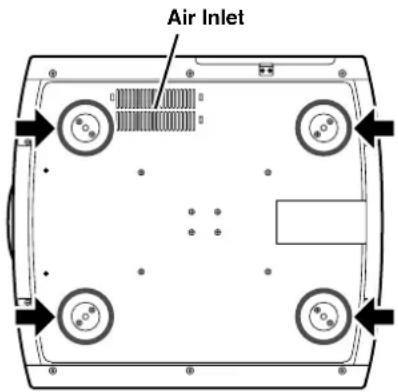
Precautions for Ceiling-mount
- To ceiling-mount this unit, special expertise and techniques are necessary. Be sure to ask your dealer (or a specialist) to perform mounting (to ceilings, etc.).
- Do not mount at places that may be subjected to vibration and shock.
- Depth of the screw holes (screw length) is 30 mm. Use screws shorter than 30 mm but longer than 19 mm. Otherwise, the screws may damage the internal parts of this unit and cause malfunction.
- Install at a safe place in case this unit or a part of it may drop. If the light-source lamp is broken, small pieces of glass from the mesh of the filter may appear outside this unit.
Projector and Screen Installation
The optimum image can be obtained when the center of this projector's lens and the screen are placed perpendicular to each other. Take note of the projection angle when placing them. Failing to do so may give rise to trapezoidal distortion of the projected image.
- This unit does not come with a function to correct trapezoidal distortion or adjust horizontal gradient.
When viewed from the left (or right)

Install the projector such that the center of the projection screen is on the same level with the center of the lens when there is a 0% shift (offset).

Install the projector such that the lower end of the projection screen is on the same level with the center of the lens when there is a 50 % shift (offset).
When viewed from the top (or bottom)

Screen Size and Projection Distance
Adjust the distance from the lens to the screen to achieve your desired screen size.
■DLA-HD10KSU/E
DLA-HD10KSU/E uses a 1.4x power zoom lens for projection, so when expanded to the maximum it can project at 1.4 times the size of the minimum.
■DLA-HD10KU/E
DLA-HD10KU/E uses a 1.9x power zoom lens for projection, so when expanded to the maximum it can project at 1.9 times the size of the minimum.
Relationship Between Projection Distance and Projection Screen Size
| Projection Screen Size Aspect Ratio 16:9 | DLA-HD10KSU/E (1.4x Zoom Lens) DLA-HD10KU/E (1.9x Zoom Lens) | |
| Approximate Projecting Distance Approximate Projecting Distance | ||
| W (Wide) - T (Tele) W (Wide) - T (Tele) | ||
| 60" (Approx. 152.4 cm) | (Approx. 1.96 m) - (Approx. 2.77 m) | (Approx. 2.58 m) - (Approx. 4.94 m) |
| 70" (Approx. 177.8 cm) | (Approx. 2.29 m) - (Approx. 3.23 m) | (Approx. 3.02 m) - (Approx. 5.78 m) |
| 80" (Approx. 203.2 cm) | (Approx. 2.63 m) - (Approx. 3.70 m) | (Approx. 3.46 m) - (Approx. 6.62 m) |
| 90" (Approx. 228.6 cm) | (Approx. 2.96 m) - (Approx. 4.17 m) | (Approx. 3.90 m) - (Approx. 7.46 m) |
| 100" (Approx. 254.0 cm) | (Approx. 3.29 m) - (Approx. 4.64 m) | (Approx. 4.34 m) - (Approx. 8.30 m) |
| 110" (Approx. 279.4 cm) | (Approx. 3.63 m) - (Approx. 5.11 m) | (Approx. 4.79 m) - (Approx. 9.14 m) |
| 120" (Approx. 304.8 cm) | (Approx. 3.96 m) - (Approx. 5.57 m) | (Approx. 5.23 m) - (Approx. 9.98 m) |
| 130" (Approx. 330.2 cm) | (Approx. 4.29 m) - (Approx. 6.04 m) | (Approx. 5.67 m) - (Approx. 10.82 m) |
| 140" (Approx. 355.6 cm) | (Approx. 4.63 m) - (Approx. 6.51 m) | (Approx. 6.11 m) - (Approx. 11.65 m) |
| 150" (Approx. 381.0 cm) | (Approx. 4.96 m) - (Approx. 6.98 m) | (Approx. 6.55 m) - (Approx. 12.49 m) |
| 160" (Approx. 406.4 cm) | (Approx. 5.30 m) - (Approx. 7.45 m) | (Approx. 6.99 m) - (Approx. 13.33 m) |
| 170" (Approx. 431.8 cm) | (Approx. 5.63 m) - (Approx. 7.91 m) | (Approx. 7.43 m) - (Approx. 14.17 m) |
| 180" (Approx. 457.2 cm) | (Approx. 5.96 m) - (Approx. 8.38 m) | (Approx. 7.88 m) - (Approx. 15.01 m) |
| 190" (Approx. 482.6 cm) | (Approx. 6.30 m) - (Approx. 8.85 m) | (Approx. 8.32 m) — |
| 200" (Approx. 508.0 cm) | (Approx. 6.63 m) - (Approx. 9.32 m) | (Approx. 8.76 m) — |
- The projection screen sizes (recommended) and projecting distances in the table above are provided only as a guide. Please use them as reference during installation.
The projected image size may vary depending on the manufacturing tolerance of the lens. - Use a projection image of 16:9 aspect ratio for setup adjustment.
Lens Shift Setting
This unit comes with a Lens Shift feature that enables upward/downward adjustment of the projection screen position. Adjust accordingly depending on the installation conditions.
- The shift level is between 0 % and 60 %. The shift level is set to 50 % as the default.
- The position of the projection screen may be out of alignment due to the gear movement.
- When lens shift setting (adjustment) is completed, mount the lens shift cover to this unit.
1Project the image on the screen
- Please refer to "Basic Operation Procedures" (Page 26) on the method of projection.
2Remove the lens shift cover
- Remove the lens shift cover from this unit using a ⊖ screwdriver.

3Adjust the projection screen position
- Turn the shift adjustment screw using a ⊖ screwdriver and adjust accordingly.
Turn clockwise : Screen shifts upwards.
Turn anti-clockwise : Screen shifts downwards.

4Mount the lens shift cover
- Mount the lens shift cover to this unit using a ⊖ screwdriver.
■Projection screen position image according to shift level

Effective Range of Remote Control Unit
The operable distance of the remote control unit is about 7 m for direct reception. The remote control unit can be used by having the transmission signal reflected off a screen.
- If the fluorescent lamp is lit, the remote control unit might not function properly.
When reflecting off a screen
Ensure that total of distance A between this unit and screen and distance B between remote control and screen is within 7 m.
- As the effect of signals reflected from the remote control unit differ with the type of screen used, operable distance may decrease.

When directing remote control unit toward this unit
When aiming the remote control unit towards the remote sensor on this unit, ensure that the distance to the sensor in front or at the rear of this unit is within 7 m.
- If the remote control fails to work properly, move closer to the unit.
- Please refer to page 12 on location of the remote sensor at the rear of this unit.

Connecting to Devices
Before connection, be sure to turn off both the projector and the device to be connected.
- Read the manual that is supplied with the device to be connected thoroughly.
Connecting to Devices
- Depending on your DVI-D cable, the signal may attenuate and the image become unstable.
- When using a DVI-D cable longer than 5 m, the use of a split system or optical fiber cable is recommended.
- Video signals that can be input to this unit are 1080/50p and 1080/60p signals for DVI-D.
![Rear side of this unit RSVICE RS-232C Connect to a [DVI] terminal DVI-D cable DVII OUTPUT](/content/2026/08/1575066/images/722edf7cec53e7d008ca7a753d5107e6a383b309aeed50d64d26e6b9868c48ad.jpg)
Control from external device
It is possible to control this unit by connecting a computer to the [RS-232C] terminal at the rear of this unit.
- Please request a connection cable from us if needed.
- For details, please consult your authorized dealer.

Connecting the Power Cord (Supplied)
Before plugging in the power cord, ensure that all devices have been connected.

1Connect the supplied power cord to the power input terminal of this unit
2Connect the earth wire to the earth terminal available in the building, followed by inserting the main plug of the supplied power cord into the wall outlet
Cautions Against Fire and Electric Shock
- Since the power consumption of this unit is high, insert the power plug directly into a wall outlet.
- When not using devices, remove the power plug from the wall outlet.
- Do not use power cords for connection other than those supplied.
- Do not use a power voltage different from that which is indicated.
- Do not cut, tear or modify the power cords. Also, do not place a heavy object on, heat or stretch the power cords as this may cause damage to the cords.
- Do not insert or pull out plugs with a wet hand.
If setting for this unit is not completed, please refer to "Adjustments and Settings Using Menus" (Page 28) upon turning on the power and perform the required setting accordingly. Once the basic setting is completed, this unit can be used by simply performing the following operation procedures.

1Removing the lens cap
- Upon using, mount the lens cap to prevent soiling of the lens.
2Turning on the power
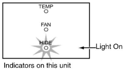
1 Insert the power plug to the power outlet
●The main power turns on and the [STAND BY] indicator on the unit lights up.

Indicators on this unit
2 Press the [OPERATE ON] button for 1 second or more
●The [OPERATE] indicator on this unit lights up and the projected image slowly appears.

Indicators on this unit
NOTES:
- Upon projection, the image may flicker for a few seconds. This is not a malfunction.
- When the light source is turned on, the lamp will slowly become brighter. It will take more than 1 minute for the brightness to stabilize.
3Adjusting zoom (screen size)
To enlarge the screen size, press the [ZOOM T] button To reduce the screen size, press the [ZOOM W] button
NOTES:
- To adjust zoom and focus, set "Zoom/Focus" in the "Options" menu to "Unlock" (default setting: "Unlock").
- When this is set to "Lock", a "not available" message will be displayed upon pressing the [ZOOM T/W] or [FOCUS +/-] button, indicating that the operation is disabled.

4Adjusting focus
To focus on nearer points, press the [FOCUS +] button To focus on farther points, press the [FOCUS -] button
5Hiding the image temporarily
Press the [HIDE] button
●The displayed image will disappear.
- Press the [HIDE] button again the restore the image.
6Turning off the power
1 Press the [OPERATE OFF] button for 1 second or more
- The [OPERATE] indicator turns off, the [STAND BY] indicator starts blinking and this unit switches to the cool down mode. The cool down mode will last for about 60 seconds to allow the temperature of the light source to cool off. (e) Page 15
●This unit switches to the standby mode at the end of the cool down mode.

Indicators on this unit
NOTE:
The [OPERATE OFF] button will not work within approximately 1 minute after the light source has been turned on. Start operation only after 1 minute's time.
2 Pull out the power plug from the power outlet
CAUTION:
Do not pull out the plug when the [STAND BY] indicator is blinking. This may shorten the lamp life and cause a malfunction.
Precautions During Use
This unit makes use of a light source lamp that may reach a high temperature during projection. Do not allow projection under the following conditions. Doing so may cause fire or malfunction of the unit.
●Projection with the unit laid on its sides
●Projection with the unit installed in an unreasonable angle
Avoid using this unit at an inclined angle. Doing so may cause unevenness in the color or shorten the lamp life.
- Projection at a location that blocks the air inlets or exhaust vents
●Projection without removing the lens cap
The menus displayed on the screen are used to perform adjustment and setting for this unit.
Menu Structure
The menus of this unit have the following structure. Characters on the screen are displayed in English only.
Main Menu Submenu (Setting Menu)
![graph TD A["1 Image Adjust Menu E.g.: Gamma setting menu"] --> B["1 Image Adjust Menu"] B --> C["E.g.: Test Pattern setting menu"] C --> D["1 Image Adjust Menu"]](/content/2026/08/1575066/images/b24a9e577c8387be296c5d99ab2d5755921f6de4d1cdd3e4d260fbc8a1c6f6d3.jpg)
E.g.: Pixel Adjust setting menu
![graph TD A["Setup Menu E.g.: Menu Position setting menu"] --> B["MenuPosition"] B --> C["Setup Setup"] C --> D["Options Setup"] D --> E["Information Setup"] A --> F["MenuDisplay"] F --> G["SleepTime"] G --> H["RS232C(bps)"] H --> I["Zoom/Focus"] I --> J["PowerSave"] J --> K["15secOn"] K --> L["30min…](/content/2026/08/1575066/images/9439bb1db9bc955b3ac499219c9148f903bc49180d61aee1eb75a8b6723bcf45.jpg)
*1 Press the [ENTER] button to switch to the test pattern image. There are 10 types of test patterns. Press the [ENTER] or [TEST] button to alter the test pattern to be projected. Press the [EXIT] button to clear the menu screen. Press the [EXIT] button again to clear the test pattern.
Menu Operation Buttons
The menus are operated using buttons on this unit or remote control unit.
 | ▲/▼: Select menu items and adjustment items.◄/►: Change setting of the selected adjustment item (setting is not possible for some items).The adjusted value will be reflected on the image immediately. | |
| Menu Operation Buttons | This Unit | |
 |  | Displays the main menu.Press to clear the menu screen when the menu is displayed. |
 |  | Confirms the selected item on the main menu.Press the [ENTER] button when the “Test Pattern” item is selected to project the test pattern on the screen. After it is projected, test pattern changes each time the [ENTER] button is pressed.Press the [ENTER] button when the “Pixel Adjust” item is selected to shift to the “H Pixel Adjust” and “V Pixel Adjust” setting screen. |
 |  | Press to return to the previous menu.Press to clear the menu screen when the main menu screen is displayed.Press to clear the displayed signal when a test pattern or green cross hatch signal is displayed. |
| ||
Procedures for Menu Operation
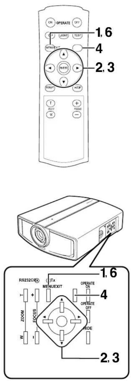
1Press the [MENU] button
●The main menu is displayed on the screen.

E.g.: Image Adjust menu
2 Press the [▲/▼] buttons to select a main menu item and press the [ENTER] button to confirm
- The "Information" menu does not have a setting menu (submenu).

E.g.: Setup menu
E.g.: Menu Position setting menu
3 Press the [▲/▼] buttons to select an adjustment item and press the [◀/▶] buttons to change the setting value

E.g.: When "Mask" value is changed from "Off" to "2.5%"
NOTES:
- Press [ENTER] after selecting "Test Pattern" on the "Image Adjust" menu. This will project the test pattern. Press the [EXIT] button to clear the menu screen. Press the [EXIT] button again to clear the test pattern.
- Press [ENTER] after selecting "Pixel Adjust" on the "Image Adjust" menu. Upon doing so, the "Pixel Adjust" submenu screen will appear.
4 After setting is completed, press the [EXIT] button
●Each time you press the button, the menu returns to the previous one.
5 Repeat procedures 2 to 4 to set other items
6 After setting is fully completed, press the [MENU] button
●The menu will disappear from the screen.
Menu Configuration
1 Image Adjust Menu
To adjust images.
Gamma
Switches the gradation characteristics of the image. Select your preference setting values according to the image to be viewed.
Setting Values: "Normal", "A", "B", "Custom" Default Value: "Normal"
NOTE:
Setting to “Custom” enables you to set (adjust) to a gamma value of your preference via the computer that is connected to the projector by using a Gamma adjustment software. (Default picture quality is equivalent to “Normal”)
You can download the Gamma adjustment software from the following website.
Adjusts the color temperature of the projected image.
Setting Values: "D65", "User1", "User2" Default Value: "D65"
Red, Green, Blue
Setting Values: -255 to 0 Default Value: "0"
- When you set the "Color Temp." setting to "User1" or "User2", adjustment of "Red,Green,Blue" can be done.
Test Pattern
Use this to adjust focus, screen size or picture quality. There are 10 types of test patterns. Press the [ENTER] or [TEST] button to alter the test pattern to be projected. Press the [EXIT] button twice to clear the test pattern.
Pixel Adjust
Fine-tunes the image position in the horizontal/vertical directions.
●This is not required under normal circumstances.
H Pixel Adjust
"Red", "Green", "Blue" Setting Values: 1 to 7 Default Value: "4"
V Pixel Adjust
"Red", "Green", "Blue" Setting Values: 1 to 7 Default Value: "4"
NOTE:
"H/V Pixel Adjust" allows fine-tuning of images in the horizontal/vertical directions up to ±3 pixels at intervals of 1 pixel for each of Red, Green and Blue. Make use of a still image with a clear outline during adjustment. This feature is intended for fine-tuning of images and therefore the effect upon adjustment may not be visible to the eye.
2 Setup Menu
Menu Position
Adjusts the display position of the menu screen.
Setting Values:

Default Value:
Mask
Masks (Hides) the outer area of the projected image.
Setting Values: "2.5%", "5%", "Off"
Default Value: "Off"
Flip H
Reverses image to the left or right.
Setting Values: "On", "Off"
Default Value: "Off"
Flip V
Inverts image upside down.
Setting Values: "On", "Off"
Default Value: "Off"
Picture Shift
When projecting images with black bands at the top and bottom (cinema image), use this to move the image up or down while retaining one of the black bands at the upper or lower end.
Setting Values: -30 to 30
Default Value: "0"
3 Options Menu
Menu Display
Adjusts the display duration of the menu screen.
Setting Values: "15sec", "On"
Default Value: "15sec"
- The menu screen display will not disappear automatically when this is set to "On". Press the [EXIT] button to clear the menu screen.
Sleep Time
Sets the lapse time before automatically switching the unit to the standby mode when there is no signal input.
Setting Values: "15min", "30min", "60min", "Off" Default Value: "Off"
RC232C (bps)
Sets the communication speed (signal transmission speed) when communicating with a computer using the RS-232C terminal. Ensure that this is same as the rate set at the computer.
Setting Values: "9600", "19200"
Default Value: "19200"
Zoom/Focus
Locks/Unlocks the power zoom/power focus functions of the projection lens.
Setting Values: "Lock", "Unlock"
Default Value: "Unlock"
Power Save
Switches the power (brightness) of the light-source lamp.
Setting Values: "On", "Off"
Default Value: "Off"
- It is possible to lower the power (brightness) of the light-source lamp when this is set to "On", but the display will appear darker than when this is set to "Off".
- Adjustment of settings will be disabled for about 1 minute after the setting is changed. In this case, adjust settings after a lapse of at least 1 minute.
- Altering the "On", "Off" setting does not affect the lamp usage time (lamp life) of the light-source lamp.
4 Information Menu
Lamp Time
Displays the accumulated hours of usage of the light-source lamp.
Source
Automatically identifies the input video signal at the [DVI] terminal of this unit and displays the signal name ("1080p50" or "1080p60").
- When there is no video signal input to the [DVI] terminal, or when there is input of a video signal that cannot be used with this unit, no signal name will be displayed.
NOTES:
- When the input video signal is switched, a blue back image will appear for about 2 seconds.
- When nothing is connected to the [DVI] terminal, or if there is no video signal, a "No Signal DVI-D" message will be projected.
- For a video signal that cannot be used with this unit, a "Out of Range" message will be projected.
●Video input signals that can be used with this unit are 1080/50p and 1080/60p signals by DVI-D.
Image for which quality at the outer area has deteriorated can be projected by masking (hiding) the outer area of the projected image.

1Project image onto the screen

2Press the [MENU] button
●The main menu is displayed on the screen.

3 Press the [▲/▼] buttons to select "Setup", followed by pressing the [ENTER] button
- The "Setup" menu appears on the right side of the screen.

4 Press the [▲/▼] buttons to select "Mask", followed by pressing the [◀/▶] buttons to select the setting value
●Masks (Hides) the outer area of the projected image.

E.g.: When "Mask" value is changed from "Off" to "2.5%"
5Press the [MENU] button to end
●The menu will disappear from the screen.
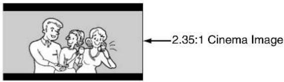
When projecting images with black bands at the top and bottom (cinema image), use this to move the image up or down while retaining one of the black bands at the upper or lower end.

1Project the image on the screen
2Press the [MENU] button
●The main menu is displayed on the screen.

3 Press the [▲/▼] buttons to select "Setup", followed by pressing the [ENTER] button
- The "Setup" menu appears on the right side of the screen.

4 Press the [▲/▼] buttons to select "Picture Shift", followed by pressing the [◀/▶] buttons to move the image upwards or downwards
- Set value in the positive (+) direction to move the image upwards and negative (−) direction to move downwards.

E.g.: When "Picture Shift" value is changed from "0" to "30"
5Press the [MENU] button to end
●The menu will disappear from the screen.
Light-source Lamp and Lamp Usage Time
The life of light-source lamps used for this unit is about 2000 hours.
- The lamp life of 2000 hours is merely the average life span of light-source lamps and we do not provide any guarantee for this figure.
The lamp life may not reach 2000 hours depending on the operating conditions.
Deterioration progresses rapidly when the remaining lamp usage time is short. Get ready or replace with a new lamp (lamp unit) when the accumulated usage time exceeds 1900 hours. Depending on the operating conditions, the lamp may have to be exchanged earlier. If the image is dark or color tone abnormal, replace the lamp as soon as possible. - You can also check the accumulated hours of usage. Please refer to "Lamp Time" of the "Information" menu. (Pages 28, 32)
- Setting “Power Save” of the “Options” menu to “On” does not affect the usage time of the light-source lamp. (Pages 28, 32)
Please consult your authorized dealer when purchasing a new lamp unit.
■Replacement Lamp (Lamp Unit) Part No.: BHL5008-S
■When the lamp usage time exceeds 1900 hours (but less than 2000 hours)
The [LAMP] indicator lights up and the [TEMP] indicator starts blinking upon turning on the power (standby mode).
The “Lamp replacement” message will be displayed on the screen when projection starts.
- The message can be cleared by pressing any button on the remote control or this unit.
■When the lamp usage time exceeds 2000 hours (but less than 2010 hours)
The [LAMP] indicator lights up and the [FAN] indicator starts blinking upon turning on the power (standby mode).
When the lamp usage time exceeds 2000 hours during projection, the "Lamp replacement" message will be displayed on the screen when projection starts and the "Warning" mark will appear blinking.
- Press the [EXIT] button to clear the display. However, the same "Warning" and "Lamp replacement" messages will be displayed after 1 hour.
- When the unit is switched to the standby mode or turned off after the lamp usage time exceeds 2000 hours, it cannot be switched back to the projection mode again. In this case, replace with a new lamp (lamp unit) and reset the lamp time (Page 38).
■When the lamp usage time reaches 2010 hours
The unit quits the projection mode (operating mode) and switches into the cool down mode.
- The [LAMP] indicator will light up and the [TEMP] and [FAN] indicators will appear blinking.
- The projection mode (operating mode) cannot be restored until a new lamp (lamp unit) is replaced and the lamp time reset.
About Lamp Replacement
- If this unit is installed in a constricted place, attempting to replace the lamp in that place may cause injury. Move this unit to a place large enough to perform work.
- Use only genuine replacement parts for the lamp unit. Otherwise, malfunction may occur. Also, never attempt to re-use an old lamp unit. This may cause marked performance deterioration or lamp blowout, thus leading to unit malfunction. Broken pieces of the lamp outside this unit may also cause injuries during lamp unit exchange.
- Do not replace the lamp immediately after this unit has been used. The temperature of the lamp is still high and this may cause a burn. Allow a cooling period of 1 hour or more before replacement.
- Before replacing the lamp unit, pull out the power plug from the outlet while the [STAND BY] indicator is still on. Replacing a lamp with the plug connected to the outlet may cause injuries or electric shocks.
Procedure for Lamp Replacement
1 Remove the control panel cover
- Please refer to page 12 for details on removing the control panel cover.

2Loosen the screws and remove the lamp cover
- Loosen the 1 screws with a ⊕ screwdriver.

3Loosen the screws on the lamp unit and lift up the handle
- Loosen the 2 screws with a ⊕ screwdriver.
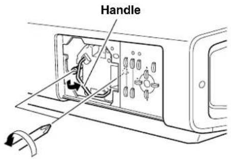
4Pull out the lamp unit

5Insert the lamp unit until it is fully in
Handling the Lamp Unit
Do not touch the glass surface of the lamp directly with your hand or stain it. Touching it with a bare hand may dirty the surface, hence shortening the lamp life, causing marked performance deterioration such as darkened screens, lamp blowout as well as malfunction.
6 Tighten the screws of the lamp unit and close the handle
- Fasten the 2 screws with a ⊕ screwdriver.
7 Attach the lamp cover and fasten the screw
- Fasten the 1 screw with a ⊕ screwdriver.
NOTE:
When fitting the lamp cover, insert the left end (with 2 claws) of the lamp cover into the unit, followed by ensuring that the protruding part on the reverse side of the lamp cover fits snugly into the hole of the unit. As this protrusion acts as a switch, misfitting may lead to failure in turning on the power.
8 Attach the control panel cover
Handling the Control Panel Cover
●The gap between this unit and the control panel cover is narrow. Be careful not to stick your finger into the gap between this unit and the control panel cover.
- Be careful of the protrusions and corners of components to avoid injury.
●After attaching the control panel cover, check that the lock is fastened. The control panel cover may drop and cause injury.


Resetting Lamp Time
After installing a new lamp (lamp unit), reset the lamp time. The lamp time counter will be reset and a new count will start.
- If the accumulated lamp time has reached 2000 hours, this unit will not work (lamp does not light up) unless the lamp time is reset.
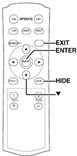
1 Insert plug into the power outlet
●The main power turns on and the [STAND BY] indicator on the unit lights up.
2Press the [EXIT], [ENTER] and [HIDE] buttons sequentially, then press the [▼] button for 2 seconds or more
- The [STAND BY] and [OPERATE] indicators will alternately blink for a duration of about 3 seconds each. After blinking stops, lamp time resets and the unit returns to the standby mode ([STAND BY] indicator lights up).
![graph TD A["EXIT"] --> B["ENTER"] B --> C["HIDE"] C --> D["Press as per normal"] D --> E["Press for 2 seconds or more"]](/content/2026/08/1575066/images/b69998fefe183aa40b58aca8abcd1c9be48a62a5557d379931e46f129e4f6fef.jpg)
To ensure the lamp time has been reset
The lamp time can be checked via the “Lamp Time” item of the “Information” menu. (Pages 28, 32)
Caution During Reset Work
Reset the lamp time only when you have replaced the lamp.
Never reset it when the lamp is still in use.
Otherwise, the approximate standard for gauging replacement time may be inaccurate, lamp performance may deteriorate and lamp blowout may occur.
Cleaning and Replacing the Filter
Clean the filter regularly. Otherwise, air intake efficiency may deteriorate and malfunction may occur. If the filter is extremely dirty and cannot be cleaned, or if it is damaged, replace the filter with a new one (inner filter: LC32058-002A). Otherwise, dirt may enter the unit and appear on the screen, preventing you from enjoying the video fully. If dirt has entered the unit or if you need information about the filter, please consult your authorized dealer.
1Pull out the plug from the power outlet
- Pull out the power plug from the outlet while the [STAND BY] indicator is still on.
2Remove the inner filter
- Push up and lift the claw at the base of the inner filter, followed by drawing out the filter.

3Clean the filter
- Clean the filter with water and dry it, avoiding direct sunlight. In extremely soiled cases, use of a neutral detergent is recommended.

CAUTIONS:
- Put on rubber gloves when using a neutral detergent.
●After washing a filter with water, make sure that the filter is completely dry before reinstalling. Otherwise, electric shocks or malfunctions may occur. - Do not clean inner filters with a vacuum cleaner. Since these filters are soft, they may be damaged if they are sucked into the vacuum cleaner.
4Reinstall the inner filter
- Check that the 2 claws at the left and right of the inner filter are locked to this unit.

What to do when these messages are displayed
| Message Cause (Details) | |
 | No device is connected to the [DVI] terminal.The DVI-D cable is connected to the [DVI] terminal but there is no signal input.→Input the video signals. |
 | A video signal that cannot be used with this unit has been input.→Input 1080/50p or 1080/60p video signals. |
 | Upon pressing the [ZOOM T/W] or [FOCUS +/-] button when “Zoom/Focus” of the “Options” menu is set to “Lock”.→Set “Zoom/Focus” of the “Options” menu to “Unlock”. |
 | At the moment when the accumulated lamp time reaches 1900 hours, a “Lamp replacement” message will be displayed.In addition, when the accumulated lamp time reaches between 1900 hours to 2000 hours, the (Lamp replacement) message will be displayed each time the projector is turned on.•The message can be cleared by pressing any button on the remote control or this unit.→Get ready a new lamp (lamp unit) in advance or replace as soon as possible. |
 | The “Lamp replacement” message will be displayed and the “Warning” word appears blinking when the accumulated lamp time exceeds 2000 hours.The message can be cleared by pressing the [EXIT] button. However, the same message will reappear every hour.When the accumulated lamp time exceeds 2000 hours, the unit cannot be turned on again once it is switched to the standby mode or turned off.If continuous projection is performed after 2000 hours, the unit will shut down upon exceeding 2010 hours and projection will be disabled.→Install a new lamp (lamp unit) and reset the lamp time.(Pages 35 - 38) |
About warning indicators
If abnormality occurs in this unit during projection, the warning mode will be triggered and the type of abnormality will be indicated by a combination of indicators displayed on the top surface of this unit.
- This unit will then automatically stop projection and run the cooling fan for about 60 seconds.
| No. | Indicator | Warning | |||||
| STAND BY OPERATE LAMP TEMP FAN HIDE | |||||||
| 1 | — | — | Light On | Blinking | — | Blinking | Lamp does not light up and unit is unable to project |
| 2 | — | — | Light On | — | Blinking | Blinking | Lamp turned off during projection |
| 3 | — | — | — | — | Blinking | Blinking | Circuits are not functioning properly (Microcomputer Circuit Operation Error) |
| 4 | — | — | — | Blinking | — | Blinking | Circuits are not functioning properly (Drive Circuit Operation Error) |
| 5 | — | — | Light On | — | — | Blinking | Lamp cover is not installed |
| 6 | — | — | — | Light On | — | Blinking | Internal temperature is abnormally high (Internal Temperature Error) |
| 7 | — | — | — | Light On | Blinking | Blinking | Temperature at air inlets are high (External Temperature Error) |
| 8 | — | — | — | — | Light On | Blinking | Inner fan has stopped (Fan Locked) |
Actions to be taken upon warning indications
Please follow the procedures below.
●For Nos. 1 - 4
No. 1 : Perform procedures to turn off/on the power again.
No. 2 : After checking if an impact shock has not occurred during operation, perform procedures to turn off/on the power again.
Nos. 3, 4: Perform procedures to turn off/on the power again.
●For Nos. 5 - 8
Pull out the power plug from the outlet while the [STAND BY] indicator is still on. After that, check No. 5 - No. 8.
No. 5 : Ensure that the lamp unit is correctly mounted onto this unit. Next, ensure that the lamp cover is correctly mounted. After that, restart according to the basic operation procedures.
No. 6 : Check that nothing is blocking the air inlets, and wait until the inside cools down. After that, restart according to the basic operation procedures.
No. 7 : Check the ambient temperature. If it is normal, leave the unit until it cools down. After that, restart according to the basic operation procedures.
No. 8 : Leave the unit until it cools down. After that, restart according to the basic operation procedures.
If the warning indication is displayed again, wait for the cooling fan to stop. Check that the [STAND BY] indicator is on, followed by removing the plug from the power outlet. Call your authorized dealer for repair.
Before sending the unit for repair, check the following points.
| Symptom Probable Cause Corrective Action Reference Page | |||
| Power is not supplied | Is the power cord disconnected? Insert the power cord (plug) properly. Page 25 | ||
| Is the lamp cover properly shut? Remove the plug when the [STAND BY] indicator is on. Close the lamp cover properly and insert the plug again. | Pages 27, 37 | ||
| Has the lamp life expired (has the lamp usage time reached 2000 hours)? | Remove the plug when the [STAND BY] indicator is on. Install a new lamp (lamp unit). Upon doing so, insert the plug. Reset the lamp time after installing a new lamp (lamp unit). | Pages 15, 35 - 38 | |
| Projected image is dark | Is the lamp near exhaustion? Check the lamp usage time on the menu. Prepare a new lamp (lamp unit) or replace as soon as possible when the lamp is near exhaustion. | Pages 15, 35 - 38 | |
| Is “Power Save” on the setting menu set to “On”? | Set the “Power Save” setting to “Off”. | Page 32 | |
| Unit works when the power is turned on but stops abruptly after a few minutes | Are the air suction openings (air inlets) and exhaust vents blocked? | Remove the plug when the [STAND BY] indicator is on. Remove any blocking object. Upon doing so, insert the plug. | Pages 11, 12, 18 |
| Are the filters dirty? Clean the filters. Page 39 | |||
| Video image does not appear | Are devices properly connected? Connect devices correctly. Page 24 | ||
| Is the lens cap removed? | Remove the lens cap. | Page 26 | |
| Are correct signals (1080/50p or 1080/60p) being output from the connected devices? | Set connected devices correctly. | Page 24 | |
| Is the video image temporarily turned off when the [HIDE] button is being pressed? | Press the [HIDE] button to display the video image again. | Page 27 | |
| Video image is fuzzy | Is the focus correctly adjusted? | Adjust accordingly using the focus button. | Page 27 |
| Is the unit placed too near or too far away from the screen? | Set the unit at a correct distance from the screen. | Page 21 | |
| Video images are missing | Has setting been performed for screen mask? | Set the “Mask” setting of the (Setup) menu to “Off”. | Page 33 |
| Has setting been performed for picture shift? | Alter the “Picture Shift” value in the “Setup” menu to ensure that images are not missing. | Page 34 | |
| Symptom Probable Cause Corrective Action Reference Page | |||
| Remote control unit does not work | Are batteries installed correctly? | Match the polarities (⊕ or ⊖) correctly when inserting the batteries. | Page 17 |
| Are batteries exhausted? Replace with new batteries. Page 17 | |||
| Is there an obstructive object between the remote control unit and remote sensor? | Remove any obstructive objects. Page 23 | ||
| Is the remote control held too far away from the sensor? | Hold the remote control closer to the sensor when using. | Page 23 | |
- This unit uses a microcomputer. External noise may cause it to malfunction. If this happens, turn off the power and remove the plug from the power outlet. Insert plug again into the outlet and check operation of the unit (see pages 26, 27 on how to turn on/off the power of the unit).
Pin Arrangement
[RS-232C] Terminal

| Pin No. | Signal Name Pin No. | Signal Name | |
| 1 N/C 6 N/C | |||
| 2 | R | D | 7 |
| 3 | T | D | 8 |
| 4 N/C 9 N/C | |||
| 5 | GND | ||
N
N
[DVI-D] Terminal
![JVC DLA-HD10KU - [DVI-D] Terminal - 1](/content/2026/08/1575066/images/637fdb1e98be7915dbaf588293a0c55585f51ff2fa2b0158ec0fdba7897fbcec.jpg)
| Pin No. | Signal Name | Pin No. | Signal Name |
| 1 | TMDS data 2- | 13 | N/C |
| 2 | TMDS data 2+ | 14 | TMDS +5 V power supply |
| 3 | TMDS data 2/4 shield | 15 | Earth (+5 V) |
| 4 | N/C | 16 | Hot plug detection |
| 5 | N/C | 17 | TMDS data 0- |
| 6 | DDC clock | 18 | TMDS data 0+ |
| 7 | DDC data | 19 | TMDS data 0/5 shield |
| 8 | N/C | 20 | N/C |
| 9 | TMDS data 1- | 21 | N/C |
| 10 | TMDS data 1+ | 22 | TMDS clock shield |
| 11 | TMDS data 1/3 shield | 23 | TMDS clock + |
| 12 | N/C | 24 | TMDS clock- |
TMDS = Transition Minimized Differential Signaling
DDC = Display Data Channel
RS-232C External Control
Control of this unit is possible via a computer by connecting the computer to this unit with a RS-232C cross cable (D-sub 9 pins). The commands to control this unit and the response data format against the received commands are explained here.
For details, please consult your authorized dealer.
1Communication Specifications
Communication specifications for this unit are as follows:
| Baud Rate 9600/19200 bps | |
| Data Length 8 bit | |
| Parity None | |
| Stop Bit 1 bit | |
| Flow Control None |
2Command Format
1 Command data format
When sending a control command to this unit, use the following data format:

| Header | :Designates the head of data and the data type. |
| ! (21h): Assigns command to the projector (Command) | |
| ? (3Fh): Query to the projector (Asking command) | |
| ID | : 1: Identification number of the projector (Factory setting is 1) |
| SP | : Designates the delimiter for ID, Command and Parameter. (20h) |
| CR | : Designates the terminal of the data. (0Dh) |
*[ ] is not necessary for Asking command
2 Response data format
Upon executing a control command it has received, this unit sends back the following response data to the computer:

| Header | : Designates the head of the data. |
| @ (40h): Fetches data from the projector | |
| ID | : 1: Identification number of the projector (Factory setting is 1) |
| SP | : Designates the delimiter for ID, Command and Parameter. (20h) |
| Normal Termination Status | : 0 (30h) |
| CR | : Designates the terminal of the data. (0Dh) |
3 Parameters used for the data format
The following 3 types of parameters are used for command and response data:
(1) Numeric value (2) ON/OFF (3) Special parameters
Each parameter is as follows:
(1) Numeric value
A 2-byte hexadecimal value (sign included) is represented by a set of 4-digit (4-byte) characters.
The range that can be specified is from "8000H" to "7FFFH"
(2) ON/OFF
Shows the status (ON or OFF) of the unit, such as POWER and HIDE.
| Character Hex Meaning | ||
| 0 | 3 | 0 |
| 1 | 3 | 1 |
| O | F | F |
| O | N |
(3) Special parameters
Operation mode parameters
| Character Hex Meaning | |
| 0000 30h 30h 30h 30h Standby mode | |
| 0001 30h 30h 30h 31h Operate mode | |
| 0002 30h 30h 30h 32h Cool down mode | |
| 0004 30h 30h 30h 34h Emergency mode |
3External control command table
| Function Command | Asking Data Type | |||||
| Operate mode | ELSE | Numeric Value | ON/OFF | Special Data | ||
| Operate | U0F | ×× | × | ○ | × | |
| HIDE | U00 | ○ | ×× | ○ | × | |
| Left/Right Reversal | U17 | ○ | ×× | ○ | × | |
| Top/Bottom Inversion | U18 | ○ | ×× | ○ | × | |
| Operation Mode | Z03 | ○ | ○ | ×× | ○ | |
Operation mode: Only Asking command is possible
| Model Name/Article Name | DLA-HD10KU/E/DLA-HD10KSU/E D-ILA Home Theater Projector |
| Emission Method | D-ILA*1 (Reflective Active Matrix Principle) |
| Display Panel/Size | D-ILA Device*2 / 0.82" (1920 pixels × 1080 pixels) × 3(Total no. of pixels: Approx. 6,220,000) |
| Projection Lens | |
| DLA-HD10KU/E 1.9x power zoom lens (2.0:1 to 3.8:1) (Power zoom/focus adjustment) | |
| DLA-HD10KSU/E 1.4x power zoom lens (1.5:1 to 2.1:1) (Power zoom/focus adjustment) | |
| Light-source Lamp 200 W Ultra-high pressure mercury lamp [Part No.: BHL5008-S] | |
| Screen Size Approx. 60" to 200" (Aspect ratio: 16:9) | |
| Projection Distance | |
| DLA-HD10KU/E Approx. 2.5 m to 15 m | |
| DLA-HD10KSU/E Approx. 2 m to 10 m | |
| Input Signal 1080/60p signal, 1080/50p signal | |
| Resolution | 1920 dots × 1080 dots |
| Input Sync Frequency Horizontal : 56.25 kHz, 67.43 kHz, 67.5 kHzVertical : 50 Hz, 59.94 Hz, 60 Hz | |
| Input Terminals | |
| VIDEO IN | DVI 1-line, DVI-D (Single-24pin) terminal, HDCP-compatible *3 |
| CONTROL | RS-232C 1-line, D-sub 9 pin × 1 (External control)SERVICE 1-line, 3.5 mm diameter, stereo mini-jack × 1 (For Service) |
| Output Terminal | |
| CONTROL | SCREEN TRIGGER 1-line, 3.5 mm diameter, monaural mini-jack × 1 |
| Power Requirements AC 100 V - 240 V AC, 50 Hz/60 Hz | |
| Rated Power | 3.5 A (100 V AC) - 1.4 A (240 V AC) |
| Operation Environment | Temperature : 41 °F to 95 °F (+5 °C to +35 °C)Humidity : 20 % to 80 % (No condensation)Storage Temperature : 14 °F to 140 °F (-10 °C to +60 °C) |
| Dimensions (Width x Height x Depth) | Approx. 20 1/5" × approx. 7 3/5" × approx. 22"(Approx. 513 mm × approx. 193.7 mm × approx. 558.5 mm)(Excluding lens and protrusion portion) |
| Mass | Approx. 37.5 lbs (Approx. 17.0 Kg) |
| Accessories | (Refer to Page 10.) |
*1 D-ILA is the abbreviation for Direct drive Image Light Amplifier.
2 D-ILA devices are manufactured using extremely high-precision technology. Pixel effectiveness is 99.99 %. Only 0.01 % or less of the pixels would either not lit up or remain permanently lit up.
*3 The image of DVI input terminal may not be displayed due to HDCP specification change.
- Design and specifications are subject to change without prior notice.
- Please note that some of the pictures and illustrations may have been abridged, enlarged or contextualized in order to aid comprehension. Images may differ from the actual product.
Dimensions (Unit: mm)
Top Bottom


Front Side


D-ILA® HOME THEATER PROJECTOR
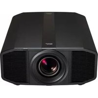
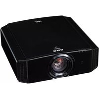
- INSTRUCTIONS MANUEL D'INSTRUCTIONS
- FOR CUSTOMER USE
- WARNING
- CAUTION
- FCC INFORMATION (U.S.A. ONLY)
- NOTE
- MACHINE NOISE INFORMATION (GERMANY ONLY)
- ABOUT BURNING-IN OF THE D-ILA DEVICE
- ABOUT THE INSTALLATION PLACE
- IMPORTANT SAFEGUARDS
- DO NOT ALLOW ANY UNQUALIFIED PERSON TO INSTALL THE UNIT
- POWER CONNECTION
- IF IN DOUBT — CONSULT A COMPETENT ELECTRICIAN
- HOW TO REPLACE THE FUSE
- POWER CONNECTION (UNITED KINGDOM ONLY)
- IMPORTANT
- ENGLISH
- INFORMATION FOR USERS ON DISPOSAL OF OLD EQUIPMENT
- ATTENTION
- [EUROPEAN UNION]
- (BUSINESS USERS)
- [OTHER COUNTRIES OUTSIDE THE EUROPEAN UNION]
- DEUTSCH
- ABOUT BURNING-IN OF D-ILA DEVICE
- VIEWING CONDITIONS (BRIGHTNESS OF ROOM)
- ENVIRONMENT OF USE
- MAINTENANCE PROCEDURES
- STANDARD FOR GAUGING REPLACEMENT TIME OF COMPONENTS
- SAFETY PRECAUTIONS
- ACCESSORIES
- CONTROLS AND FEATURES
- INSTALLING THE PROJECTOR
- CONNECTING TO VARIOUS DEVICES
- BASIC OPERATION PROCEDURES
- ADJUSTMENTS AND SETTINGS USING MENUS
- SCREEN MASKING
- PICTURE SHIFT SETTING
- REPLACING THE LAMP
- CLEANING AND REPLACING THE FILTER
- WHAT TO DO WHEN THESE MESSAGES ARE DISPLAYED
- WARNING INDICATION
- TROUBLESHOOTING
- TERMINAL DESCRIPTION
- SPECIFICATIONS
- OPTIONAL ACCESSORIES
- FRONT SIDE/TOP SURFACE/BOTTOM SURFACE
- INDICATOR
- AIR INLETS (2 IN FRONT AND 1 AT BOTTOM SURFACE)
- POWER ZOOM LENS
- REMOTE SENSOR (FRONT)
- LENS CAP
- LENS SHIFT COVER
- FOOT
- FILTER
- REAR SIDE/RIGHT SIDE
- CONTROL PANEL COVER
- HANDLING THE CONTROL PANEL COVER
- EXHAUST VENT
- AC POWER INPUT TERMINAL
- REMOTE SENSOR (REAR)
- SCREEN TRIGGER TERMINAL
- [SERVICE] TERMINAL
- [RS-232C] TERMINAL (D-SUB 9 PIN)
- [DVI] TERMINAL (DVI-D 24 PIN)
- CONTROL PANEL
- [RX/TX] INDICATOR
- [MENU] BUTTON
- [EXIT] BUTTON
- [ZOOM T/W] BUTTON
- [FOCUS +/-] BUTTON
- CURSOR [▲/▼/◄/►] BUTTONS
- [ENTER] BUTTON
- [OPERATE ON] BUTTON
- [OPERATE OFF] BUTTON
- [HIDE] BUTTON
- INDICATORS
- [STAND BY] INDICATOR
- [OPERATE] INDICATOR
- [LAMP] BUTTON
- [TEMP] INDICATOR
- [FAN] INDICATOR
- [HIDE] INDICATOR
- INDICATOR DISPLAY
- ABOUT COOL DOWN MODE
- REMOTE CONTROL
- REMOTE CONTROL'S SIGNAL TRANSMITTER
- [LIGHT] BUTTON
- [CHP] (CROSS HATCH PATTERN) BUTTON
- CURSOR [▲ / ▼ / ◀ / ▶] BUTTONS
- [PRESET] BUTTON
- [TEST] BUTTON
- LOADING BATTERIES INTO THE REMOTE CONTROL
- OPEN THE BACK COVER
- LOAD THE BATTERIES
- CLOSE THE BACK COVER
- PRECAUTIONS FOR USING BATTERIES
- BATTERY LIFE
- BATTERY LEAKAGE
- PRECAUTIONS FOR INSTALLATION
- INSTALLATION ENVIRONMENT PRECAUTIONS FOR USAG
- THIS UNIT IS A PRECISION DEVICE. DO NOT INSTALL IT AT THE FOLLOWING PLACES. DOING SO MAY CAUSE FIRE OR MALFUNCTION OF THE UNIT
- THIS UNIT MAKES USE OF A LIGHT SOURCE LAMP THAT MAY REACH A HIGH TEMPERATURE DURING PROJECTION. DO NOT ALLOW PROJECTION UNDER THE FOLLOWING CONDITIONS. DOING SO MAY CAUSE FIRE OR MALFUNCTION OF THE UNIT
- MINIMUM SPACE REQUIRED
- MOUNTING THIS UNIT
- PRECAUTIONS FOR CEILING-MOUNT
- PROJECTOR AND SCREEN INSTALLATION
- WHEN VIEWED FROM THE LEFT (OR RIGHT)
- WHEN VIEWED FROM THE TOP (OR BOTTOM)
- SCREEN SIZE AND PROJECTION DISTANCE
- DLA-HD10KSU/E
- DLA-HD10KU/E
- LENS SHIFT SETTING
- PROJECT THE IMAGE ON THE SCREEN
- REMOVE THE LENS SHIFT COVER
- ADJUST THE PROJECTION SCREEN POSITION
- MOUNT THE LENS SHIFT COVER
- EFFECTIVE RANGE OF REMOTE CONTROL UNIT
- WHEN REFLECTING OFF A SCREEN
- WHEN DIRECTING REMOTE CONTROL UNIT TOWARD THIS UNIT
- CONNECTING TO DEVICES
- CONTROL FROM EXTERNAL DEVICE
- CONNECTING THE POWER CORD (SUPPLIED)
- CAUTIONS AGAINST FIRE AND ELECTRIC SHOCK
- REMOVING THE LENS CAP
- TURNING ON THE POWER
- INSERT THE POWER PLUG TO THE POWER OUTLET
- PRESS THE [OPERATE ON] BUTTON FOR 1 SECOND OR MORE
- NOTES
- ADJUSTING ZOOM (SCREEN SIZE)
- ADJUSTING FOCUS
- HIDING THE IMAGE TEMPORARILY
- PRESS THE [HIDE] BUTTON
- TURNING OFF THE POWER
- PRESS THE [OPERATE OFF] BUTTON FOR 1 SECOND OR MORE
- PULL OUT THE POWER PLUG FROM THE POWER OUTLET
- PRECAUTIONS DURING USE
- MENU STRUCTURE
- MENU OPERATION BUTTONS
- PROCEDURES FOR MENU OPERATION
- PRESS THE [MENU] BUTTON
- PRESS THE [▲/▼] BUTTONS TO SELECT A MAIN MENU ITEM AND PRESS THE [ENTER] BUTTON TO CONFIRM
- PRESS THE [▲/▼] BUTTONS TO SELECT AN ADJUSTMENT ITEM AND PRESS THE [◀/▶] BUTTONS TO CHANGE THE SETTING VALUE
- AFTER SETTING IS COMPLETED, PRESS THE [EXIT] BUTTON
- REPEAT PROCEDURES 2 TO 4 TO SET OTHER ITEMS
- AFTER SETTING IS FULLY COMPLETED, PRESS THE [MENU] BUTTON
- MENU CONFIGURATION
- IMAGE ADJUST MENU
- GAMMA
- RED, GREEN, BLUE
- TEST PATTERN
- PIXEL ADJUST
- H PIXEL ADJUST
- V PIXEL ADJUST
- SETUP MENU
- MENU POSITION
- MASK
- FLIP H
- FLIP V
- PICTURE SHIFT
- OPTIONS MENU
- MENU DISPLAY
- SLEEP TIME
- RC232C (BPS)
- ZOOM/FOCUS
- POWER SAVE
- INFORMATION MENU
- LAMP TIME
- SOURCE
- PROJECT IMAGE ONTO THE SCREEN
- PRESS THE [▲/▼] BUTTONS TO SELECT "SETUP", FOLLOWED BY PRESSING THE [ENTER] BUTTON
- PRESS THE [▲/▼] BUTTONS TO SELECT "MASK", FOLLOWED BY PRESSING THE [◀/▶] BUTTONS TO SELECT THE SETTING VALUE
- PRESS THE [MENU] BUTTON TO END
- PRESS THE [▲/▼] BUTTONS TO SELECT "PICTURE SHIFT", FOLLOWED BY PRESSING THE [◀/▶] BUTTONS TO MOVE THE IMAGE UPWARDS OR DOWNWARDS
- LIGHT-SOURCE LAMP AND LAMP USAGE TIME
- REPLACEMENT LAMP (LAMP UNIT) PART NO.: BHL5008-S
- WHEN THE LAMP USAGE TIME EXCEEDS 1900 HOURS (BUT LESS THAN 2000 HOURS)
- WHEN THE LAMP USAGE TIME EXCEEDS 2000 HOURS (BUT LESS THAN 2010 HOURS)
- WHEN THE LAMP USAGE TIME REACHES 2010 HOURS
- ABOUT LAMP REPLACEMENT
- PROCEDURE FOR LAMP REPLACEMENT
- REMOVE THE CONTROL PANEL COVER
- LOOSEN THE SCREWS AND REMOVE THE LAMP COVER
- LOOSEN THE SCREWS ON THE LAMP UNIT AND LIFT UP THE HANDLE
- PULL OUT THE LAMP UNIT
- INSERT THE LAMP UNIT UNTIL IT IS FULLY IN
- HANDLING THE LAMP UNIT
- TIGHTEN THE SCREWS OF THE LAMP UNIT AND CLOSE THE HANDLE
- ATTACH THE LAMP COVER AND FASTEN THE SCREW
- ATTACH THE CONTROL PANEL COVER
- RESETTING LAMP TIME
- INSERT PLUG INTO THE POWER OUTLET
- PRESS THE [EXIT], [ENTER] AND [HIDE] BUTTONS SEQUENTIALLY, THEN PRESS THE [▼] BUTTON FOR 2 SECONDS OR MORE
- TO ENSURE THE LAMP TIME HAS BEEN RESET
- CAUTION DURING RESET WORK
- PULL OUT THE PLUG FROM THE POWER OUTLET
- REMOVE THE INNER FILTER
- CLEAN THE FILTER
- CAUTIONS
- REINSTALL THE INNER FILTER
- ABOUT WARNING INDICATORS
- ACTIONS TO BE TAKEN UPON WARNING INDICATIONS
- PLEASE FOLLOW THE PROCEDURES BELOW
- PIN ARRANGEMENT
- [RS-232C] TERMINAL
- [DVI-D] TERMINAL
- RS-232C EXTERNAL CONTROL
- COMMUNICATION SPECIFICATIONS
- COMMAND FORMAT
- COMMAND DATA FORMAT
- RESPONSE DATA FORMAT
- PARAMETERS USED FOR THE DATA FORMAT
- NUMERIC VALUE
- ON/OFF
- SPECIAL PARAMETERS
- EXTERNAL CONTROL COMMAND TABLE
Brand : JVC
Model : DLA-HD10KU
Category : Projector