BDEG900 - Grinder BLACK & DECKER - Free user manual and instructions
Find the device manual for free BDEG900 BLACK & DECKER in PDF.

| Product type | Angle grinder |
| Brand | Black & Decker |
| Model | BDEG900 |
| Maximum wheel diameter | 228 mm (9 inches) |
| Power supply | Mains (corded) |
| Rated voltage | 120 V |
| No-load speed | 6000 rpm (estimated) |
| Main functions | Grinding, sanding, wire brushing, abrasive cutting |
| Auxiliary handle | Yes, 3 positions (side and top) |
| Guard | Yes, for grinding; cutting guard optional (ref. 1004484-02) |
| Spindle lock | Yes, for accessory change |
| Approximate weight | 5.5 kg |
| Dimensions (L x W x H) | Not specified |
| Maintenance and cleaning | Clean motor housing with compressed air; use mild soap and a damp cloth for exterior |
| Safety | Wear eye, hearing and respiratory protection; always use the appropriate guard |
| Compatible accessories | Type 27 and 1 grinding wheels, sanding discs, wire brushes with 5/8 in - 11 hub thread |
| Repairability | Not user repairable; take to an authorized Black & Decker center |
| Warranty | 2 years for domestic use |
Frequently Asked Questions - BDEG900 BLACK & DECKER
User questions about BDEG900 BLACK & DECKER
0 question about this device. Answer the ones you know or ask your own.
Ask a new question about this device
Download the instructions for your Grinder in PDF format for free! Find your manual BDEG900 - BLACK & DECKER and take your electronic device back in hand. On this page are published all the documents necessary for the use of your device. BDEG900 by BLACK & DECKER.
USER MANUAL BDEG900 BLACK & DECKER
9 inch (228mm) Large Angle Grinder INSTRUCTION MANUAL
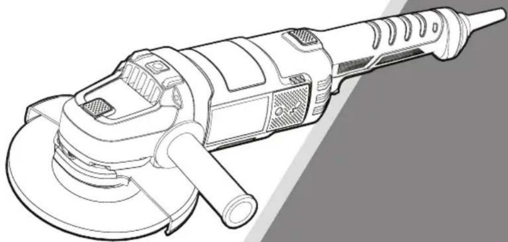
natural_image
Technical line drawing of a power tool with meshing and central hub (no text or symbols)CATALOG NUMBER BDEG900
Thank you for choosing Black & Decker! To register your new product, go to www.BlackandDecker.com/NewOwner
PLEASE READ BEFORE RETURNING THIS PRODUCT FOR ANY REASON.
If you have a question or experience a problem with your Black & Decker purchase, go to http://www.blackanddecker.com/instantanswers
If you can't find the answer or do not have access to the Internet, call 1-800-544-6986 from 8 a.m. to 5 p.m. EST Mon. - Fri. to speak with an agent. Please have the catalog number available when you call.
SAVE THIS MANUAL FOR FUTURE REFERENCE.
It is important for you to read and understand this manual. The information it contains relates to protecting YOUR SAFETY and PREVENTING PROBLEMS. The symbols below are used to help you recognize this information.
⚠️ DANGER: Indicates an imminently hazardous situation which, if not avoided, will result in death or serious injury.
⚠ WARNING: Indicates a potentially hazardous situation which, if not avoided, could result in death or serious injury.
⚠️ CAUTION: Indicates a potentially haz ard ous situation which, if not avoided, may result in minor or mod er ate injury.
NOTICE: Used without the safety alert symbol indicates potentially hazardous situation which, if not avoided, may result in property damage.
General Power Tool Safety Warnings
⚠ WARNING: Read all safety warnings and all instructions. Failure to follow the warnings and instructions may result in electric shock, fire and/or serious injury.
SAVE ALL WARNINGS AND INSTRUCTIONS FOR FUTURE REFERENCE
The term "power tool" in the WARNINGS refers to your mains-operated (corded) power tool or battery-operated (cordless) power tool.
SAVE THESE INSTRUCTIONS
1) WORK AREA SAFETY
a) Keep work area clean and well lit. Cluttered or dark areas invite accidents.
b) Do not operate power tools in explosive atmospheres, such as in the presence of flammable liquids, gases or dust. Power tools create sparks which may ignite the dust or fumes.
c) Keep children and bystanders away while operating a power tool. Distractions can cause you to lose control.
2) ELECTRICAL SAFETY
a) Power tool plugs must match the outlet. Never modify the plug in any way. Do not use any adapter plugs with earthed (grounded) power tools. Unmodified plugs and matching outlets will reduce risk of electric shock.
b) Avoid body contact with earthed or grounded surfaces such as pipes, radiators, ranges and refrigerators. There is an increased risk of electric shock if your body is earthed or grounded.
c) Do not expose power tools to rain or wet conditions. Water entering a power tool will increase the risk of electric shock.
d) Do not abuse the cord. Never use the cord for carrying, pulling or unplugging the power tool. Keep cord away from heat, oil, sharp edges or moving parts. Damaged or entangled cords increase the risk of electric shock.
e) When operating a power tool outdoors, use an extension cord suitable for outdoor use. Use of a cord suitable for outdoor use reduces the risk of electric shock.
f) If operating a power tool in a damp location is unavoidable, use a ground fault circuit interrupter (GFCI) protected supply. Use of a GFCI reduces the risk of electric shock.
3) PERSONAL SAFETY
a) Stay alert, watch what you are doing and use common sense when operating a power tool. Do not use a power tool while you are tired or under the influence of drugs, alcohol or medication. A moment of inattention while operating power tools may result in serious personal injury.
b) Use personal protective equipment. Always wear eye protection. Protective equipment such as dust mask, nonskid safety shoes, hard hat, or hearing protection used for appropriate conditions will reduce personal injuries.
c) Prevent unintentional starting. Ensure the switch is in the off position before connecting to power source and/or battery pack, picking up or carrying the tool. Carrying power tools with your finger on the switch or energizing power tools that have the switch on invites accidents.
d) Remove any adjusting key or wrench before turning the power tool on. A wrench or a key left attached to a rotating part of the power tool may result in personal injury.
e) Do not overreach. Keep proper footing and balance at all times. This enables better control of the power tool in unexpected situations.
f) Dress properly. Do not wear loose clothing or jewelry. Keep your hair, clothing and gloves away from moving parts. Loose clothes, jewelry or long hair can be caught in moving parts.
g) If devices are provided for the connection of dust extraction and collection facilities, ensure these are connected and properly used. Use of dust collection can reduce dust-related hazards.
4) POWER TOOL USE AND CARE
a) Do not force the power tool. Use the correct power tool for your application. The correct power tool will do the job better and safer at the rate for which it was designed.
b) Do not use the power tool if the switch does not turn it on and off. Any power tool that cannot be controlled with the switch is dangerous and must be repaired.
c) Disconnect the plug from the power source and/or the battery pack from the power tool before making any adjustments, changing accessories, or storing power tools. Such preventive safety measures reduce the risk of starting the power tool accidentally.
d) Store idle power tools out of the reach of children and do not allow persons unfamiliar with the power tool or these instructions to operate the power tool. Power tools are dangerous in the hands of untrained users.
e) Maintain power tools. Check for misalignment or binding of moving parts, breakage of parts and any other condition that may affect the power tool's operation. If damaged, have the power tool repaired before use. Many accidents are caused by poorly maintained power tools.
f) Keep cutting tools sharp and clean. Properly maintained cutting tools with sharp cutting edges are less likely to bind and are easier to control.
g) Use the power tool, accessories and tool bits, etc. in accordance with these instructions, taking into account the working conditions and the work to be performed. Use of the power tool for operations different from those intended could result in a hazardous situation.
5) SERVICE
a) Have your power tool serviced by a qualified repair person using only identical replacement parts. This will ensure that the safety of the power tool is maintained.
SAFETY INSTRUCTIONS FOR ALL OPERATIONS
Safety Warnings Common for Grinding, Sanding, Wire Brushing, or Abrasive, Cutting-Off Operations
a) This power tool is intended to function as a grinder, sander, wire brush, or cut-off tool. Read all safety warnings, instructions, illustrations and specifications provided with this power tool. Failure to follow all instructions listed below may result in electric shock, fire and/or serious injury.
b) Operations such as polishing are not recommended to be performed with this power tool. Operations for which the power tool was not designed may create a hazard and cause personal injury.
c) Do not use accessories which are not specifically designed and recommended by the tool manufacturer. Just because the accessory can be attached to your power tool, it does not assure safe operation.
d) The rated speed of the accessory must be at least equal to the maximum speed marked on the power tool. Accessories running faster than their rated speed can break and fly apart.
e) The outside diameter and the thickness of your accessory must be within the capacity rating of your power tool. Incorrectly sized accessories cannot be adequately guarded or controlled.
f) Threaded mounting of accessories must match the grinder spindle thread. For accessories mounted by flanges, the arbor hole of the accessory must fit the locating diameter of the flange. Accessories that do not match the mounting hardware of the power tool will run out of balance, vibrate excessively and may cause loss of control.
g) Do not use a damaged accessory. Before each use inspect the accessory such as abrasive wheel for chips and cracks, backing pad for cracks, tear or excess wear, wire brush for loose or cracked wires. If power tool or accessory is dropped, inspect for damage or install an undamaged accessory. After inspecting and installing an accessory, position yourself and bystanders away from the plane of the rotating accessory and run the power tool at maximum no-load speed for one minute. Damaged accessories will normally break apart during this test time.
h) Wear personal protective equipment. Depending on application, use face shield, safety goggles or safety glasses. As appropriate, wear dust mask, hearing protectors, gloves and work shop apron capable of stopping small abrasive or workpiece fragments. The eye protection must be capable of stopping flying debris
generated by various operations. The dust mask or respirator must be capable of filtrating particles generated by your operation. Prolonged exposure to high intensity noise may cause hearing loss.
i) Keep bystanders a safe distance away from work area. Anyone entering the work area must wear personal protective equipment. Fragments of workpiece or of a broken accessory may fly away and cause injury beyond immediate area of operation.
j) Hold the power tool by insulated gripping surfaces only, when performing an operation where the cutting accessory may contact hidden wiring or its own cord. Cutting accessory contacting a “live” wire may make exposed metal parts of the power tool “live” and shock the operator.
k) Position the cord clear of the spinning accessory. If you lose control, the cord may be cut or snagged and your hand or arm may be pulled into the spinning accessory.
I) Never lay the power tool down until the accessory has come to a complete stop. The spinning accessory may grab the surface and pull the power tool out of your control.
m) Do not run the power tool while carrying it at your side. Accidental contact with the spinning accessory could snag your clothing, pulling the accessory into your body.
n) Regularly clean the power tool's air vents. The motor's fan will draw the dust inside the housing and excessive accumulation of powdered metal may cause electrical hazards.
o) Do not operate the power tool near flammable materials. Sparks could ignite these materials.
p) Do not use accessories that require liquid coolants. Using water or other liquid coolants may result in electrocution or shock.
q) Do not use Type 11 (flaring cup) wheels on this tool. Using inappropriate accessories can result in injury.
r) Always use side handle. Tighten the handle securely. The side handle should always be used to maintain control of the tool at all times.
s) When starting the tool with a new or replacement wheel, or a new or replacement wire brush installed, hold the tool in a well protected area and let it run for one minute. If the wheel has an undetected crack or flaw, it should burst in less than one minute. If the wire brush has loose wires, they will be detected. Never start the tool with a person in line with the wheel. This includes the operator.
t) To prevent the spindle end from contacting the bottom of the hole of the abrasive product, use accessories that have a threaded hole depth of at least 21mm. Failure to use an accessory with the appropriate thread depth could result in damage to the abrasive product and injury to the operator or persons in the area.
u) The arbor size of wheels, flanges, backing pads or any other accessory must properly fit the spindle of the power tool. Accessories with arbor holes that do not match the mounting hardware of the power tool will run out of balance, vibrate excessively and may cause loss of control.
KICKBACK AND RELATED WARNINGS
Kickback is a sudden reaction to a pinched or snagged rotating wheel, backing pad, brush or any other accessory. Pinching or snagging causes rapid stalling of the rotating accessory which in turn causes the uncontrolled power tool to be forced in the direction opposite of the accessory's rotation at the point of the binding. For example, if an abrasive wheel is snagged or pinched by the workpiece, the edge of the wheel that is entering into the pinch point can dig into the surface of the material causing the wheel to climb out or kick out. The wheel may either jump toward or away from the operator, depending on direction of the wheel's movement at the point of pinching. Abrasive wheels may also break under these conditions. Kickback is the result of tool misuse and/or incorrect operating procedures or conditions and can be avoided by taking proper precautions as given below:
a) Maintain a firm grip on the power tool and position your body and arm to allow you to resist kickback forces. Always use auxiliary handle, if provided, for maximum control over kickback or torque reaction during start up. The operator can control torque reaction or kickback forces, if proper precautions are taken.
b) Never place your hand near the rotating accessory. Accessory may kickback over your hand.
c) Do not position your body in the area where power tool will move if kickback occurs. Kickback will propel the tool in direction opposite to the wheel's movement at the point of snagging.
d) Use special care when working corners, sharp edges etc. Avoid bouncing and snagging the accessory. Corners, sharp edges or bouncing have a tendency to snag the rotating accessory and cause loss of control or kickback.
e) Do not attach a saw chain woodcarving blade or toothed saw blade. Such blades create frequent kickback and loss of control.
SAFETY WARNINGS SPECIFIC FOR GRINDING AND ABRASIVE CUTTING-OFF OPERATIONS
a) Use only wheel types that are re- commended for your power tool and the specific guard designed for the selected wheel. Wheels for which the power tool was not designed cannot be adequately guarded and are unsafe.
b) The grinding surface of center depressed wheels must be mounted below the plane of the guard lip. An improperly mounted wheel that projects through the plane of the guard lip cannot be adequately protected.
c) The guard must be securely attached to the power tool and positioned for maximum safety, so the least amount of wheel is exposed towards the operator. The guard helps to protect operator from broken wheel fragments and accidental contact with wheel.
d) Wheels must be used only for recommended applications. For example: do not grind with the side of cut-off wheel. Abrasive cut-off wheels are intended for peripheral grinding, side forces applied to these wheels may cause them to shatter.
e) Always use undamaged wheel flanges that are of correct size and shape for your selected wheel. Proper wheel flanges support the wheel thus reducing the possibility of wheel breakage. Flanges for cut-off wheels may be different from grinding wheel flanges.
f) Do not use worn down wheels from larger power tools. Wheel intended for larger power tool is not suitable for the higher speed of a smaller tool and may burst.
ADDITIONAL SAFETY WARNINGS SPECIFIC FOR ABRASIVE CUTTING-OFF OPERATION
a) Do not “jam” the cut-off wheel or apply excessive pressure. Do not attempt to make an excessive depth of cut. Over stressing the wheel increases the loading and susceptibility to twisting or binding of the wheel in the cut and the possibility of kickback or wheel breakage.
b) Do not position your body in line with and behind the rotating wheel. When the wheel, at the point of operation, is moving away from your body, the possible kickback may propel the spinning wheel and the power tool directly at you.
c) When wheel is binding or when interrupting a cut for any reason, switch off the power tool and hold the power tool motionless until the wheel comes to a complete stop. Never attempt to remove the cut-off wheel from the cut while the wheel is in motion otherwise kickback may occur. Investigate and take corrective action to eliminate the cause of wheel binding.
d) Do not restart the cutting operation in the workpiece. Let the wheel reach full speed and carefully reenter the cut. The wheel may bind, walk up or kickback if the power tool is restarted in the workpiece.
e) Support panels or any oversized workpiece to minimize the risk of wheel pinching and kickback. Large workpieces tend to sag under their own weight. Supports must be placed under the workpiece near the line of cut and near the edge of the workpiece on both sides of the wheel.
f) Use extra caution when making a “pocket cut” into existing walls or other blind areas. The protruding wheel may cut gas or water pipes, electrical wiring or objects that can cause kickback.
g) It is recommended to use grinding/cutting wheels no thicker than 1/4 inch (6mm) thick and no larger than 9 inch (228mm) diameter.
SAFETY WARNINGS SPECIFIC FOR SANDING OPERATIONS
a) Do not use excessively oversized sanding disc paper. Follow manufacturers recommendations, when selecting sanding paper. Larger sanding paper extending beyond the sanding pad presents a laceration hazard and may cause snagging, tearing of the disc or kickback.
SAFETY WARNINGS SPECIFIC FOR WIRE BRUSHING OPERATIONS
a) Be aware that wire bristles are thrown by the brush even during ordinary operation. Do not overstress the wires by applying excessive load to the brush. The wire bristles can easily penetrate light clothing and/or skin.
b) If the use of a guard is recommended for wire brushing, do not allow any interference of the wire wheel or brush with the guard. Wire wheel or brush may expand in diameter due to work and centrifugal forces.
c) Safety glasses: Safety Goggles or safety glasses with side shields and a full face shield compliant with ANSI Z87.1 eye protection (CAN/CPA Z94.3), must be worn by the operator and others that are within 50 feet of the use of this product/accessory.
ADDITIONAL SAFETY INFORMATION
- Do not use Type 1 flat cut-off abrasive or diamond wheels without proper guard.
⚠ WARNING: Always wear proper personal hearing protection that
conforms to ANSI S12.6 (S3.19) during use. Under some conditions and duration of use, noise from this product may contribute to hearing loss.
⚠ WARNING: ALWAYS use safety glasses. Everyday eyeglasses are NOT safety glasses. Also use face or dust mask if cutting operation is dusty. ALWAYS WEAR CERTIFIED SAFETY EQUIPMENT:
• ANSI Z87.1 eye protection (CAN/CSA Z94.3),
• ANSI S12.6 (S3.19) hearing protection,
• NIOSH/OSHA/MSHA respiratory protection.
⚠ WARNING: Some dust created by power sanding, sawing, grinding, drilling, and other construction activities contains chemicals known to the state of California to cause cancer, birth defects or other reproductive harm. Some examples of these chemicals are:
• lead from lead-based paints,
• crystalline silica from bricks and cement and other masonry products, and
• arsenic and chromium from chemically-treated lumber.
Your risk from these exposures varies, depending on how often you do this type of work. To reduce your exposure to these chemicals: work in a well ventilated area, and work with approved safety equipment, such as those dust masks that are specially designed to filter out microscopic particles.
- Avoid prolonged contact with dust from power sanding, sawing, grinding, drilling, and other construction activities. Wear protective clothing and wash exposed areas with soap and water. Allowing dust to get into your mouth, eyes, or lay on the skin may promote absorption of harmful chemicals.
⚠ WARNING: Use of this tool can generate and/or disperse dust, which may cause serious and permanent respiratory or other injury. Always use NIOSH/OSHA approved respiratory protection appropriate for the dust exposure. Direct particles away from face and body.
⚠ WARNING: Do not operate this tool for long periods of time. Vibration caused by the operating action of this tool may cause permanent injury to fingers, hands, and arms. Use gloves to provide extra cushion, take frequent rest periods, and limit daily time of use.
⚠ WARNING: When not in use, place grinder on a stable surface where it will not move inadvertently, roll or cause a tripping or falling hazard. The grinder may stand upright on the battery pack but may be easily knocked over. Serious personal injury may result.
⚠ WARNING: The grinding wheel or accessory may loosen during coast-down of the tool when shut off. If grinding wheel or accessory loosens, it may dismount from the machine and may cause serious personal injury.
⚠CAUTION: To reduce the risk of personal injury, use extra care when working into a corner or edge because a sudden, sharp movement of the tool may be experienced when the wheel or other accessory contacts a secondary surface or a surface edge.
- When using an extension cord, be sure to use one heavy enough to carry the current your product will draw. An undersized cord will cause a drop in line voltage resulting in loss of power and overheating. The following table shows the correct size to use depending on cord length and nameplate ampere rating. If in doubt, use the next heavier gage. The smaller the gage number, the heavier the cord.
| MINIMUM GAUGE FOR CORD SETS | |||||
| Volts | Total Length of Cord in Feet | ||||
| 120V | 0-25(0-7,6m) | 26-50(7,6-15,2m) | 51-100(15,2-30,4m) | 101-150(30,4-45,7m) | |
| Ampere Rating | |||||
| More | Not more | American Wire Gauge | |||
| Than | Than | ||||
| 6 - | 10 18 | 16 | 14 | 12 | |
SYMBOLS
- The label on your tool may include the following symbols. The symbols and their definitions are as follows:
V....volts A....amperes
Hz......hertz W......watts
min......minutes \~ or AC......alternating current
or DC...direct current n......rated speed
Class I Construction earthing terminal
(grounded) ......safety alert symbol
☐ ......Class II Construction .../min or rpm....revolutions or reciprocation
(double insulated) per minute
Read instruction manual before use
Use proper eye protection
O Use proper hearing protection
Use proper respiratory protection
FUNCTIONAL DESCRIPTION
-
On/off switch
-
Lock off button
-
Auxiliary handle
-
Spindle lock
-
Guard
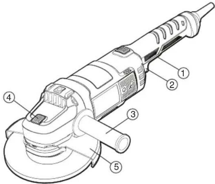
text_image
Technical diagram of a power tool with numbered parts for identificationASSEMBLY
⚠ WARNING: To prevent accidental operation, turn off and unplug tool before performing the following operations. Failure to do this could result in serious personal injury.
AUXILIARY HANDLE
WARNING: This handle SHOULD BE USED AT ALL TIMES to maintain complete control of the tool.
An auxiliary 3 position handle is furnished with your grinder. It can be screwed into either side or the top of the gear case housing.
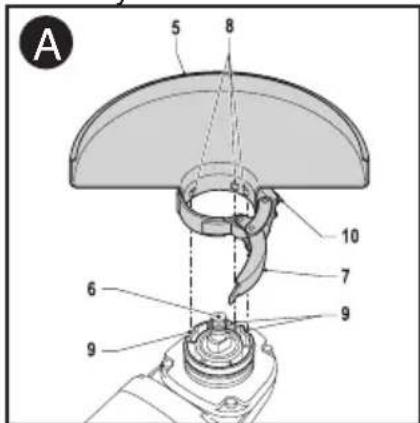
Fitting and removing the guard (fig. A)
The tool is supplied with a guard intended for grinding purposes only. If the unit is
intended to perform cutting off operations, a guard specific for this operation must be fitted. A suitable guard for cutting off operations part number 1004484-02 is available and can be obtained from Black & Decker service centers.
Fitting
⚠️CAUTION: Do not tighten the adjusting screw with the latch in the open position. Undetectable damage to the guard or the mounting hub may result.
⚠️CAUTION: If the guard cannot be tightened by the guard latch, do not use the tool and take the tool and guard to a service center to repair or replace the guard.
text_image
A 5 8 6 10 7 9 6 9- Place the tool on a table, with the spindle (6) facing up.
- Release the clamping lock (7) and hold the guard (5) over the tool as shown.
- Align the lugs (8) with the notches (9).
- Press the guard down and rotate it counterclockwise to the required position.
- Fasten the clamping lock (7) to secure the guard to the tool.
- If required, tighten the screw (10) to increase the clamping force.
Removing
⚠ WARNING: Always use the guard when operating the tool, except when sanding.
- Release the clamping lock (7).
- Rotate the guard clockwise to align the lugs (8) with the notches (9).
- Remove the guard from the tool.
Fitting and removing grinding or cutting discs (fig. B - D)
Always use the correct type of disc for your application. Always use discs with the correct diameter and bore size.
Fitting
• Fit the guard as described above.
- Place the inner flange (11) onto the spindle (6) as shown (fig. B). Make sure that the flange is correctly located on the flat sides of the spindle.
- Place the disc (12) onto the spindle (6) as shown (fig. B). If the disc has a raised center (13), make sure that the raised center faces the inner flange.
- Make sure that the disc locates correctly on the inner flange.
- Place the outer flange (14) onto the spindle. When fitting a grinding disc, the raised center on the outer flange must face towards the disc (A in fig. C). When fitting a cutting disc, the raised center on the outer flange must face away from the disc (B in fig. C).
- Keep the spindle lock (4) depressed and tighten the outer flange using the two-pin spanner (15) (fig. D).
Removing
- Keep the spindle lock (4) depressed and loosen the outer flange (14) using the two-pin spanner (15) (fig. D).
- Remove the outer flange (14) and the disc (11).
Fitting and removing sanding discs and backing pad (fig. D & E)
For sanding, a backing pad is required. The backing pad is available from your Black & Decker dealer as an accessory. NOTE: Guard may be removed when using sanding backing pads.
⚠ WARNING: Proper guard must be reinstalled for grinding wheel, sanding flap disc, cutting wheel, wire brush or wire wheel applications after sanding applications are complete.
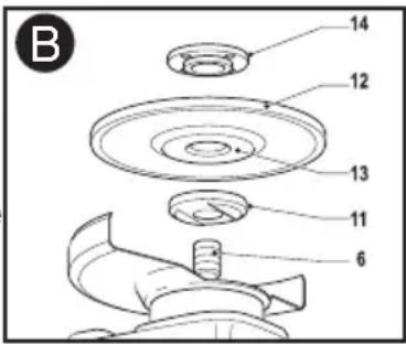
text_image
B 14 12 13 11 6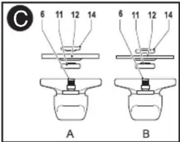
text_image
C 6 11 12 14 6 11 12 14 A B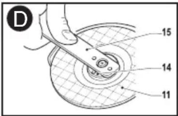
text_image
D 15 14 11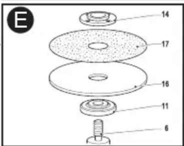
text_image
E 14 17 16 11 6Fitting
- Place the inner flange (11) onto the spindle (6) as shown (fig. E). Make sure that the flange is correctly located on the flat sides of the spindle.
- Place the backing pad (16) onto the spindle.
- Place the sanding disc (17) onto the backing pad.
- Place the outer flange (14) onto the spindle with the raised center facing away from the disc.
- Keep the spindle lock (3) depressed and tighten the outer flange using the two-pin spanner (15) (fig. D). Make sure that the outer flange is fitted correctly and that the disc is clamped tightly.
Removing
- Keep the spindle lock (4) depressed and loosen the outer flange (14) using the two-pin spanner (15) (fig. D).
- Remove the outer flange (14), the sanding disc (17) and the backing pad (16).
MOUNTING AND USING WIRE BRUSHES AND WIRE WHEELS
Wire cup brushes or wire wheels screw directly on the grinder spindle without the use of flanges. Use only wire brushes or wheels provided with a 5/8 inch-11 threaded hub.
A Type 27 guard is required when using wire brushes and wheels. Wear work gloves when handling wire brushes and wheels. They can become sharp.
Wheel or brush must not touch guard when mounted or while in use. Undetectable damage could occur to the accessory, causing wires to fragment from accessory wheel or cup.
MOUNTING WIRE CUP BRUSHES AND WIRE WHEELS
Turn off tool and unplug tool before making any adjustments or removing or installing attachments or accessories.
- Thread the wheel on the spindle by hand.
- Depress spindle lock button and use a wrench on the hub of the wire wheel or brush to tighten the wheel.
- To remove the wheel, reverse the above procedure.
Failure to properly seat the wheel hub before turning the tool on may result in damage to tool or wheel.
OPERATION
⚠ WARNING: This tool should not be used in temperatures below -4°F (-20°C) or above 104°F (40°C).
Switching on and off
⚠️CAUTION: Hold the auxiliary handle and trigger handle firmly to maintain control of the tool at start up and during use and until the wheel or accessory stops rotating. Make sure the wheel has come to a complete stop be fore laying the tool down.
NOTE: To reduce unexpected tool movement, do not switch the tool on or off while under load conditions. Allow the grinder to run up to full speed before touching the work surface. Lift the tool from the surface before turning the tool off. Allow the tool to stop rotating before putting it down.
- To switch the tool on, press the lock-off button (2) and subsequently press the on/off switch (1).
- To switch the tool off, release the on/off switch (1). Warning! Do not switch the tool off while under load.
SPINDLE LOCK
⚠ WARNING: To prevent accidental operation, turn off and unplug tool before performing the following operations. Failure to do this could result in serious personal injury.
The spindle lock button (4) is provided to prevent the spindle from rotating when installing or removing wheels. Operate the spindle lock only when the tool is turned off and the
wheel has come to a complete stop.
⚠ WARNING: Do not engage the spindle lock while the tool is operating. Damage to the tool will result and attached accessory may spin off possibly resulting in injury.
- To engage the lock, depress the spindle lock button (4) shown in figure F and rotate the spindle until you are unable to rotate the spindle further.
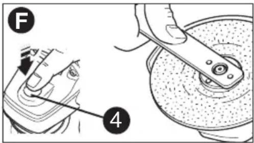
text_image
F 4SURFACE GRINDING WITH GRINDING WHEELS
- Allow the tool to reach full speed before touching the tool to the work surface.
- Apply minimum pressure to the work surface, allowing the tool to operate at high speed. Grinding rate is greatest when the tool operates at high speed.
- Maintain a 20° to 30° angle between the tool and work surface.
- Continuously move the tool in a forward and back motion to avoid creating gouges in the work surface.
- Remove the tool from work surface before turning tool off. Allow the tool to stop rotating before laying it down.
EDGE GRINDING WITH GRINDING WHEELS
⚠️CAUTION: Wheels used for edge grinding and cutting may break or kick back if they bend or twist while the tool is being used to do cut-off work. In all edge grinding / cutting operations the open side of the guard must be positioned away from the operator. Edge grinding / cutting with thicker Type 27 wheels (1/4" / 6mm thick) using a Type 27 guard must be limited to shallow cutting and notching (less than 1/2 inch (13mm) in depth). A Type 1 closed guard is required for all other edge grinding / cutting. Edge grinding / cutting with thinner Type 27/Type 42 wheels (1/8" / 3mm thick and less) requires a closed Type 1 guard and must be limited to shallow cutting and notching (less than 1/2 inch (13mm) in depth). Use a closed type 1 guard for all edge grinding / cutting with a Type 1/Type 41 cut-off wheels.
- Allow the tool to reach full speed before touching the tool to the work surface.
- Apply minimum pressure to the work surface, allowing the tool to operate at high speed. Grinding rate is greatest when the tool operates at high speed.
- Position yourself so that the open-underside of the wheel is facing away from you.
- Once a cut is begun and a notch is established in the workpiece, do not change the angle of the cut. Changing the angle will cause the wheel to bend and may cause wheel breakage. Edge grinding wheels are not designed to withstand side pressures caused by bending.
- Remove the tool from the work surface before turning the tool off. Allow the tool to stop rotating before laying it down.
⚠️CAUTION: Do not use edge grinding wheels / cutting wheels for surface grinding applications because these wheels are not designed for side pressures encountered with surface grinding. Wheel breakage and injury may result.
USING WIRE CUP BRUSHES AND WIRE WHEELS
Wire wheels and brushes can be used for removing rust, scale and paint, and for smoothing irregular surfaces.
NOTE: The same precautions should be taken when wire brushing paint as when sanding paint.
- Allow the tool to reach full speed before touching the tool to the work surface.
- Apply minimum pressure to work surface, allowing the tool to operate at high speed. Material removal rate is greatest when the tool operates at high speed.
- Maintain a 5° to 10° angle between the tool and work surface for wire cup brushes.
- Maintain contact between the edge of the wheel and the work surface with wire wheels.
- Continuously move the tool in a forward and back motion to avoid creating gouges in the work surface. Allowing the tool to rest on the work surface without moving, or moving the tool in a circular motion causes burning and swirling marks on the work surface.
- Remove the tool from the work surface before turning the tool off. Allow the tool to stop rotating before setting it down.
Use extra care when working over an edge, as a sudden sharp movement of grinder may be experienced.
SURFACE FINISHING WITH SANDING FLAP DISCS
- Allow the tool to reach full speed before touching the tool to the work surface.
- Apply minimum pressure to work surface, allowing the tool to operate at high speed. Sanding rate is greatest when the tool operates at high speed.
- Maintain a 5° to 10° angle between the tool and work surface.
- Continuously move the tool in a forward and back motion to avoid creating gouges in the work surface.
- Remove the tool from work surface before turning tool off. Allow the tool to stop rotating before laying it down.
USING SANDING BACKING PADS
Choose the proper grit sanding discs for your application. Sanding discs are available in various grits. Coarse grits yield faster material removal rates and a rougher finish. Finer grits yield slower material removal and a smoother finish.
Begin with coarse grit discs for fast, rough material removal. Move to a medium grit paper and finish with a fine grit disc for optimal finish.
Coarse 16 - 30 grit
Medium 36 - 80 grit
Fine Finishing 100 - 120 grit
Very Fine Finishing 150 - 180 grit
-
Allow the tool to reach full speed before touching tool to the work surface.
-
Apply minimum pressure to work surface, allowing the tool to operate at high speed.
Sanding rate is greatest when the tool operates at high speed.
- Maintain a 5^ to 15^ angle between the tool and work surface. The sanding disc should contact approximately one inch (25mm) of work surface.
- Move the tool constantly in a straight line to prevent burning and swirling of work surface. Allowing the tool to rest on the work surface without moving, or moving the tool in a circular motion causes burning and swirling marks on the work surface.
- Remove the tool from work surface before turning tool off. Allow the tool to stop rotating before laying it down.
PRECAUTIONS TO TAKE WHEN SANDING PAINT
- Sanding of lead based paint is NOT RECOMMENDED due to the difficulty of controlling the contaminated dust. The greatest danger of lead poisoning is to children and pregnant women.
- Since it is difficult to identify whether or not a paint contains lead without a chemical analysis, we recommend the following precautions when sanding any paint:
PERSONAL SAFETY
- No children or pregnant women should enter the work area where the paint sanding is being done until all clean up is completed.
- A dust mask or respirator should be worn by all persons entering the work area. The filter should be replaced daily or whenever the wearer has difficulty breathing.
NOTE: Only those dust masks suitable for working with lead paint dust and fumes should be used. Ordinary painting masks do not offer this protection. See your local hardware dealer for the proper N.I.O.S.H. approved mask. - NO EATING, DRINKING or SMOKING should be done in the work area to prevent ingesting contaminated paint particles. Workers should wash and clean up BEFORE eating, drinking or smoking. Articles of food, drink, or smoking should not be left in the work area where dust would settle on them.
ENVIRONMENTAL SAFETY
- Paint should be removed in such a manner as to minimize the amount of dust generated.
- Areas where paint removal is occurring should be sealed with plastic sheeting of 4 mils thickness.
- Sanding should be done in a manner to reduce tracking of paint dust outside the work area.
CLEANING AND DISPOSAL
- All surfaces in the work area should be vacuumed and thoroughly cleaned daily for the duration of the sanding project. Vacuum filter bags should be changed frequently.
- Plastic drop cloths should be gathered up and disposed of along with any dust chips or other removal debris. They should be placed in sealed refuse receptacles and disposed of through regular trash pick-up procedures.
During clean up, children and pregnant women should be kept away from the immediate work area. - All toys, washable furniture and utensils used by children should be washed thoroughly before being used again.
MAINTENANCE
If the replacement of the power supply cord is necessary, it must be done by an authorized service center or other qualified service personnel.
CLEANING
⚠ WARNING: Blowing dust and grit out of the motor housing using compressed air is a necessary maintenance procedure. Dust and grit from metal grinding often accumulate on interior surfaces and could create an electrical shock hazard if not cleaned out.
• Always handle accessories with care when mounting or removing.
- The best storage place for accessories is one that is cool and dry away from direct sunlight and excess heat or cold.
Use only mild soap and a damp cloth to clean the tool. Never let any liquid get inside the tool; never immerse any part of the tool into a liquid.
IMPORTANT: To assure product SAFETY and RELIABILITY, repairs, maintenance and adjustment (other than those listed in this manual) should be performed by authorized service centers or other qualified service personnel, always using identical replacement parts.
Problem
TROUBLESHOOTING
Possible Cause
Possible Solution
- Unit will not start. • Cord not plugged in. • Plug tool into a working outlet.
- Circuit fuse is blown. • Replace circuit fuse. (If the product repeatedly causes the circuit fuse to blow, discontinue use immediately and have it serviced at a Black and Decker service center or authorized
servicer.)
- Circuit breaker is tripped. - Reset circuit breaker. (If the product repeatedly causes the circuit breaker to trip, discontinue use immediately and have it serviced at a
Black and Decker service center
or authorized servicer.)
- Cord or switch is damaged. - Have cord or switch replaced at a Black and Decker Service Center or Authorized Servicer
For assistance with your product, visit our website www.blackanddecker.com for the location of the service center nearest you or call the BLACK & DECKER help line at 1-800-544-6986.
This Class B digital apparatus complies with Canadian ICES-003. This device complies with part 15 of the FCC rules. Operation is subject to the following two conditions: (1) This device may not cause harmful interference, and (2) this device must accept any interference received, including interference that may cause undesired operation.
NOTE: This equipment has been tested and found to comply with the limits for Class B digital device, pursuant to part 15 of the FCC Rules. These limits are designed to provide reasonable protection against harmful interference in a residential installation. This equipment generates, uses and can radiate radio frequency energy and, if not installed and used in accordance with the instructions, may cause harmful interference to radio or television reception, which can be determined by turning the equipment off and on, the user is encouraged to try to correct the interference by one or more of the following measures:
- Reorient or relocate the receiving antenna. - Increase the separation between the equipment and the receiver.
- Connect the equipment into an outlet on a circuit different from that to which the receiver is connected.
- Consult the dealer or an experienced radio/TV technician for help.
LUBRICATION
Black and Decker tools are properly lubricated at the factory and are ready for use. Tools should be lubricated regularly every year depending on usage. (Tools used on heavy duty jobs and tools exposed to heat may require more frequent lubrication.) This lubrication should be attempted only by trained power tool repair person such as those at Black and Decker service centers or in other qualified service personnel.
REPLACEMENT PARTS
Use only identical replacement parts. For a parts list or to order parts, visit our service website at www.blackanddecker.com. You can also order parts from your nearest Black and Decker Factory Service Center or Black and Decker Authorized Warranty Service Center. Or, you can call our Customer Care Center at 1-800-544-6986.
SERVICE AND REPAIRS
All quality tools will eventually require servicing and/or replacement of parts. For information about Black and Decker, its factory service centers or authorized warranty service centers, visit our website at www.blackanddecker.com or call our Customer Care Center at 1-800-544-6986. All repairs made by our service centers are fully guaranteed against defective material and workmanship. We cannot guarantee repairs made or attempted by others.
You can also write to us for information at Black and Decker, 701 E. Joppa Road, Towson, Maryland 21286 - Attention: Product Service. Be sure to include all of the information shown on the nameplate of your tool (model number, type, serial number, etc.).
ACCESSORIES
Recommended accessories for use with your tool are available from your local dealer or authorized service center. If you need assistance regarding accessories, please call:
1-800-544-6986.
⚠ WARNING: The use of any accessory not recommended for use with this tool could be hazardous.
SERVICE INFORMATION
All Black & Decker Service Centers are staffed with trained personnel to provide customers with efficient and reliable power tool service. Whether you need technical advice, repair, or genuine factory replacement parts, contact the Black & Decker location nearest you. To find your local service location, call 1-800-544-6986 or visit
www.blackanddecker.com
LIMITED TWO-YEAR HOME USE WARRANTY
Black & Decker (U.S.) Inc. warrants this product for two years against any defects in material or workmanship. The defective product will be replaced or repaired at no charge in either of two ways.
The first, which will result in exchanges only, is to return the product to the retailer from whom it was purchased (provided that the store is a participating retailer). Returns should be made within the time period of the retailer's policy for exchanges (usually 30 to 90 days after the sale). Proof of purchase may be required. Please check with the retailer for their specific return policy regarding returns that are beyond the time set for exchanges. The second option is to take or send the product (prepaid) to a Black & Decker owned or authorized Service Center for repair or replacement at our option. Proof of purchase may be required.
This warranty does not apply to accessories. This warranty gives you specific legal rights and you may have other rights which vary from state to state or province to province. Should you have any questions, contact the manager of your nearest Black & Decker Service Center. This product is not intended for commercial use.
FREE WARNING LABEL REPLACEMENT: If your warning labels become illegible or are missing, call 1-800-544-6986 for a free replacement.
LATIN AMERICA: This warranty does not apply to products sold in Latin America. For products sold in Latin America, check country specific warranty information contained in the packaging, call the local company or see the website for warranty information.the packaging, call the local company or see the website for warranty information.
Imported by
Black & Decker (U.S.) Inc.,
701 E. Joppa Rd.
Towson, MD 21286 U.S.A.

BlackandDecker.com
1-800-544-6986
natural_image
Line drawing of a mechanical power tool with a circular base and radial blade (no text or symbols)NUMERO DE CATALOGUE BDEG900
text_image
Technical diagram of a power tool with numbered parts for identificationASSEMBLAGE
INSTALLATION ET DÉPOSE DU PARE-MAIN (FIG. A)
natural_image
Technical line drawing of a mechanical power tool with a circular base and radial blade (no text or symbols)CATÁLOGO N°
BDEG900
text_image
Technical diagram of a power tool with numbered parts for identificationENSAMBLAJE
Date of purchase · Fecha de compra Invoice No. · No. de factura
Col. Fracc. Universidad
Chihuahua, Chihuahua
Tel. 01 614 413 64 04
Fernando González Armenta
Bolivia No. 605
Col. Felipe Carrillo Puerto
Cd. Madero, Tamaulipas
Tel. 01 833 221 34 50