
BKS 450 Plus - Motorcycle METABO - Free user manual and instructions
Find the device manual for free BKS 450 Plus METABO in PDF.

| Product Type | Table saw (jobsite saw) |
| Brand | Metabo |
| Model | BKS 450 Plus |
| Table dimensions | 1030 mm (L) x 660 mm (W) |
| Table extension dimensions | 800 mm (L) x 500 mm (W) |
| Table height | 850 mm |
| Total height | 1020 mm |
| Approximate total weight | 94 kg |
| Supply voltage | 400 V / 3~50 Hz |
| Rated current | 7.5 A |
| Fuse protection (min.) | 16 A |
| Power consumption (P1) | 5.5 kW (S6 40%) |
| Useful power (P2) | 3.2 kW (S1 100%) |
| Engine speed | 2800 rpm |
| Cutting speed | 66 m/s |
| Saw blade diameter | 400 mm |
| Maximum cutting height | 140 mm |
| Protection type | IP 54 |
| Guaranteed sound power level | 109 dB(A) |
| Main functions | Adjustable parallel fence, cross stop with miter cut (0-45°), push stick, protection cover, riving knife, emergency stop switch, under-voltage relay |
| Maintenance and cleaning | Regular cleaning of sawdust, oiling of cross stop guide, checking blade/riving knife gap (3-8 mm), checking cable and plug |
| Safety | Protection cover, riving knife, push stick, emergency stop switch, hearing and eye protection, mandatory use of personal protective equipment |
| Spare parts and repairability | CV and HM saw blades, accessories (wheeled stand, extraction sleeve, maintenance spray), repairs by qualified Metabo personnel |
| General information | 60-page user manual, available in multiple languages, free download |
Frequently Asked Questions - BKS 450 Plus METABO
User questions about BKS 450 Plus METABO
0 question about this device. Answer the ones you know or ask your own.
Ask a new question about this device
Download the instructions for your Motorcycle in PDF format for free! Find your manual BKS 450 Plus - METABO and take your electronic device back in hand. On this page are published all the documents necessary for the use of your device. BKS 450 Plus by METABO.
USER MANUAL BKS 450 Plus METABO
1. Overview of the Saw
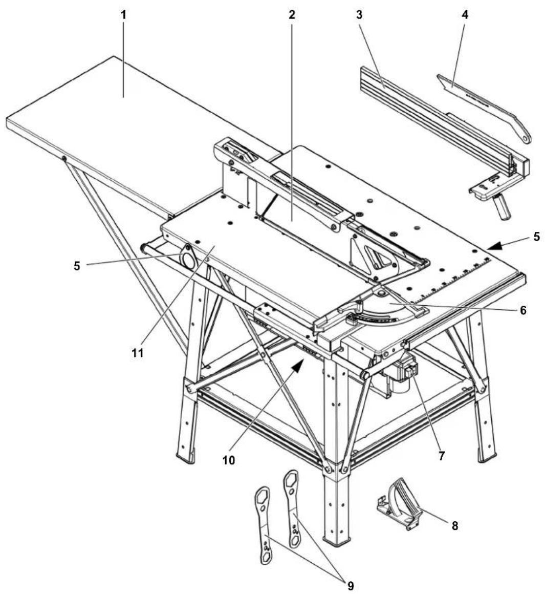
9 Spanner for saw blade change
10 Motor unit / Chip case
11 Table top
1 Table extension
2 Blade guard
3 Rip fence
4 Push stick
5 Crane lifting eye
6 Mitre fence with wedge cutting jig
7 ON/OFF switch with emergency off switch
8 Handle for push block
Table of Contents
- Overview of the Saw. 19
- Please Read First! 20
- Safety Instructions 20
3.1 Specified conditions of use 20
3.2 General safety instructions ....20
3.3 Symbols on the machine 22
3.4 Safety devices 22 - Special Product Features.... 23
- Operating elements 23
- Set-up. 24
6.1 Setting up the machine 24
6.2 Table extension 24
6.3 Mains connection.. 24
6.4 Chip and dust extraction unit ... 25 - Operation 25
7.1 Sawing with the rip fence..... 26
7.2 Sawing with the metre fence.... 27
7.3 Cutting wedges.. 27 - Tips and tricks 28
- Care and maintenance 28
9.1 Changing the saw blade 28
9.2 Aligning the riving knife 29
9.3 Saw storage.. 29
9.4 Maintenance 29 - Transport 30
- Available Accessories.. 30
- Repair 30
- Protection of the Environment 30
- Troubleshooting 30
- Technical Data 31
2. Please Read First!
These operating instructions have been written so that you can quickly learn how to operate your saw safely. Here is a guide on how you should read these instructions:
- Read these instructions before use. Pay special attention to the safety information.
- These instructions are intended for persons with basic technical knowledge regarding the operation of a device like the one described herein. Inexperienced persons are strongly advised to seek competent advice and guidance from an experienced person before operating this machine.
- Keep all documents supplied with the tool so that you and all other users can access them at any time.
Retain proof of purchase for any future warranty claims.
- If you lend or sell this device be sure to have these operating instructions go with it.
- The equipment manufacturer is not liable for any damage resulting from disregard of these operating instructions.
Information in these instructions is designated as follows:

Danger!
Risk of personal injury or environmental damage.

Risk of electric shock!
Risk of personal injury by electric shock.

Drawing-in/trapping hazard!
Risk of personal injury by body parts or clothing being drawn into the rotating saw blade.

Caution!
Risk of material damage.

Note:
Additional information.
- Numbers in illustrations (1, 2, 3 etc.)
- indicate component parts;
- are consecutively numbered;
- relate to the corresponding number(s) in brackets (1), (2), (3) etc. in the neighbouring text.
- Numbered steps must be carried out in sequence.
- Instructions which can be carried out in any order are indicated by a bullet point () .
- Listings are marked by a dash (-).
3. Safety Instructions
3.1 Specified conditions of use
This machine is intended for ripping, cross-cutting and cutting to size of solid wood, particle board, fibreboard, plywood and these materials provided they have plastic laminate surfaces or edge trim or are veneered.
Round workpieces may not be sawed as they can be twisted by the rotating saw blade.
The tool must not be used for grooving. Always have blade guard installed during operation.
Any other use is considered to be not as specified and not permitted. The manufacturer is not liable for any damage caused by unspecified use.
Reconstruction of this machine or use of parts that have not been tested and released by the manufacturer can lead to unforeseen damage and dangers during operation.
3.2 General safety instructions
- When using this machine observe the following safety instructions to minimise the risk of personal injury or material damage.
- Please also observe the special safety instructions in the respective sections.
- Where applicable, follow the legal directives or regulations for the prevention of accidents pertaining to the use of circular saws.

General hazards!
- Keep your work area tidy - a messy work area invites accidents.
- Be alert. Know what you are doing. Set out to work with reason. Do not operate device while under the influence of drugs, alcohol or medication.
- Consider environmental conditions. Keep work area well lighted.
- Avoid unnatural body positions. Ensure firm footing and keep your balance at all times.
-
Use suitable workpiece supports when cutting long stock.
-
Sparks may be created when working with contaminated workpieces. Do not operate the machine near in-flammable liquids or gases, or in explosion hazard areas.
The saw shall only be started and operated by persons familiar with circular saws and who are aware of the dangers associated with the operation of such machines at all times.
Persons under 18 years of age shall use this tool only in the course of their vocational training under the supervision of an instructor.
- Keep bystanders, particularly children, out of the danger zone. Do not permit bystanders to touch the device or mains cable while it is running.
- Do not overload device - use it only within the performance range it was designed for (see 'Technical Data').
Danger! Risk of electric shock!
- Avoid exposing the machine to the rain if possible. Avoid operating the machine in a damp or wet environment. Prevent body contact with earthed objects such as radiators, pipes, cooking stoves, refrigerators when operating this machine. Store the machine in dry areas. Do not clean the machine with a water jet or hose.
- Do not use the mains cable for any purpose it is not intended for.
Risk of personal injury and crushing by moving parts!
- Do not operate the machine without installed guards.
Always keep sufficient distance to the saw blade. Use suitable feeding aids if necessary. Keep sufficient distance to driven components when operating the device. - Wait for the saw blade to come to a complete stop before removing cut-outs, waste wood etc. from the work area.
-
Do not attempt to stop the saw blade by pushing the workpiece against its side.
-
Ensure the device is disconnected from power before servicing.
- When turning ON the machine (e.g. after servicing) ensure that no tools or loose parts are left on or in the machine.
- Turn power OFF if the machine is not used.
- Please note that the electrical motor brake will not work during a power outage, and it will take longer for the saw blade to come to a stop.
Cutting hazard, even with the cutting tool at standstill!
- Wear gloves when changing cutting tools.
- Store saw blades in such a manner that nobody can get hurt.
Risk of kickback (workpiece is caught by the saw blade and thrown against the operator)!
Always work with a properly set riv- ing knife.
- Riving knife and saw blade used must match: The riving knife should be thinner than the kerf, but thicker than the saw blade body.
- Do not jam workpieces.
- Make sure the saw blade is suitable for the workpiece material.
- Cut thin or thin-walled workpieces only with fine-toothed saw blades.
Always use sharp saw blades.
- Check workpieces for foreign objects (for example nails or screws).
- Cut only stock of dimensions that allow for safe and secure holding while cutting.
- Never cut several workpieces at the same time – and also never cut bundles containing several individual pieces. There is a risk of personal injury if individual pieces are caught by the saw blade in an uncontrolled manner.
- Remove small cut-outs, waste wood etc. from the work area - when you are doing so, the saw blade must be at a complete standstill.

Drawing-in/trapping hazard!
- Ensure that no parts of the body or clothing can be caught and drawn in by rotating components (no ties, no gloves, no loose-fitting clothes; contain long hair with hairnet).
- Never attempt to cut any workpieces which contain
-ropes,
-strings,
-bands,
-cables or
-wires or to which any of the above are attached.

Danger due to insufficient perprotection equipment!
- Wear ear protection.
- Wear safety goggles.
Wear dust mask. - Wear suitable work clothes.
- When working outdoors wearing of non-slip shoes is recommended.

Risk of injury by inhaling dust!
- Some types of wood dust (e.g. oak, beech, ash) may cause cancer when inhaled. If working in a closed room, always use a dust collector.
Make sure that as little as possible wood dust can escape into the environment:
install dust collector
- repair any leaks on the dust collector
- keep your work area well ventilated at all times.
Operation without a dust collector is only possible:
outdoors;
- for short-term operation (up to a maximum of 30 minutes); or
- if a dust respirator is worn.

Hazard caused by modifica- of the machine or use of parts
not tested and approved by the manufacturer!
- Use only parts approved by the equipment manufacturer. This applies particularly to:
-saw blades (see'Technical Data for stock numbers) - safety devices (see 'Spare parts list' for stock numbers).
- Do not change any parts.

Hazard caused by machines!
- Keep the machine and accessories in good repair. Follow the maintenance instructions.
- Before any use check machine for possible damage: before operating the machine all safety devices, protective guards or slightly damaged parts need to be checked for proper function as specified. Check to see that all moving parts work properly and do not jam. All parts must be correctly installed and meet all requirements for proper operation of the device.
- Immediately report faults and disruptions after noting them.
- Any damaged parts or protection devices must be repaired or replaced by a qualified specialist. Have damaged switches replaced by a service centre. Do not use this machine if the switch cannot be switched on or off.

Risk of injury by noise!
- Wear ear protection.
Make sure the riving knife is not bent. A bent riving knife will push the workpiece against the side of the saw blade, causing noise. - Use very sharp saw blades to reduce noise and save energy.

Danger from blocking work- s or workpiece parts!
If blockage occurs:
- Switch machine OFF.
-
Unplug mains cable.
-
Wear gloves.
- Clear the blockage using a suitable tool.
3.3 Symbols on the machine
Data on the nameplate
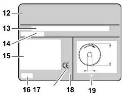
12 Manufacturer
13 Serial number
14 Machine designation
15 Motor data (see also 'Technical Data')
16 Date of manufacture
17 CE mark - This machine meets the EC directives as per declaration of conformity
18 Waste disposal symbol - Device can be disposed of by returning it to the manufacturer
19 Dimensions of permissible saw blades
Symbols on the machine

20 21


22 23 24
20 Wear ear protection
21 Wear eye protection
22 Read operating instructions
23 Do not reach into saw blade area
24 Hazardous area warning
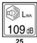
25 Guaranteed sound power level
3.4 Safety devices
Riving knife
The riving knife (26) prevents the workpiece from being caught by the rising teeth of the saw blade and being thrown back against the operator.
The riving knife is coordinated with the saw blade diameter given in the technical data and must always be installed during operation.
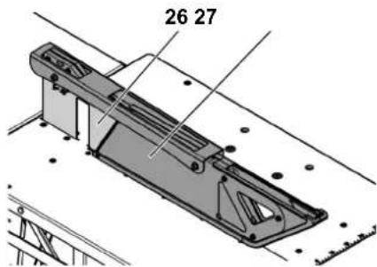
Blade guard
The blade guard (27) protects against unintentional contact with the saw blade and from chips flying about.
The blade guard is coordinated with the saw blade diameter given in the technical data and must always be installed during operation.
The chip guard must lower independently, and may not become stuck in the top position.
Push stick
The push stick (28) serves as an extension of the hand and protects against accidental contact with the saw blade.
Always use the push stick if the distance between saw blade and rip fence is less than 120~mm
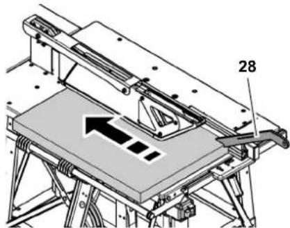
The push stick must be guided at an angle of 20^ to 30^ to the saw table surface.
Replace the push stick if it is damaged.
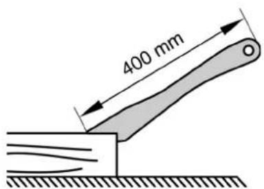
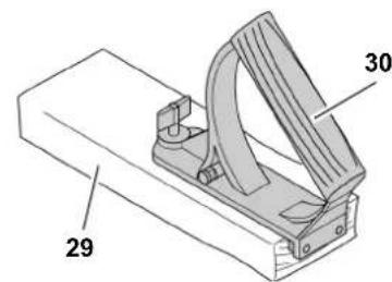
Handle for push block
The handle for the push block (30) is screwed to a matching board (29). It is used for safe guidance of relatively small workpieces.
The board should be 400mm long, at least 200mm wide and 15 - 20mm high.
The push block handle must be replaced if damaged.
4. Special Product Features
- Mitre fence
with adjustable angle
with wedge cutting jig.
Rip fence
with two profiles of differing height for adaptation to thin or thick workpieces;
-
fence extrusion continuously adjustable in longitudinal direction for adaptation to workpiece length; and
-
continuously adjustable in transverse direction for adaptation to workpiece width.
-
All operating elements are located at the machine's front.
-
Table extension included in standard delivery:
-permanently screwed to work stand.
- An undervoltage relay prevents the power tool from starting up when power is restored after a power failure.
Robust sheet steel construction high load-bearing capacity and permanent protection against corrosion.
Push stick can be clipped to rip fence for easy access.
5. Operating elements
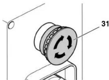
Emergency off switch (BKS 450 Plus only)
Activating the emergency off switch (31) will stop the saw blade as quickly as possible.
The emergency off switch may only be activated in an emergency situation. Activate the emergency off switch immediately if there is a danger of personal injury or property damage.
ON/OFF switch
To start = press green switch button (32).
To stop = press red switch button (33).
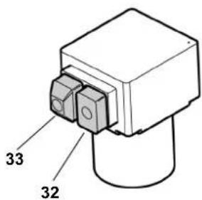
i Note:
In case of a power failure an undervoltage relay trips. This prevents the power tool from starting when the power is restored. To restart, press the green switch button again.
Fences
The saw is equipped with two fences:
- Mitre fence (for cross-cuts / mitre cuts):
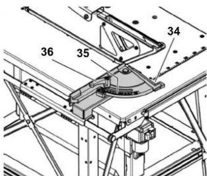
Additionally a wedge cutting jig (34) is integrated into the metre fence.
The angle for metre cuts can be adjusted continuously between 0^ and 45^ on the angle scale (35). The lock lever (36) for fixing in place must always be tightened for cutting with the metre fence.
i Note:
The distance between the fence extrusion of the metre fence and the saw blade is preset in the factory and cannot be adjusted.
- Rip fence (for ripping):
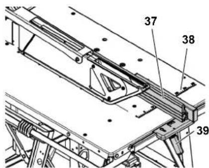
The fence extrusion (37) must be parallel to the saw blade for cutting with the rip fence. For cutting with the rip fence it must be fixed in place with the lock lever (39).
Wing nuts (43) for attaching and removing the fence extrusion:
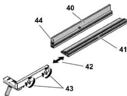
High auxiliary fence (40):
- for cutting thick stock.
Low auxiliary fence (41):
- for cutting thin stock.
Length adjustment (42): - for adjusting the rip fence for the workpiece length.
Using the scale stamped on the saw table (38) you can set the distance from the rip fence to the saw blade.
If you do not need the push stick you can fasten it via the clip (44) to the rip fence profile for easy access at all times.
6. Set-up

Danger!
Modifications to the saw or use of parts not tested and released by the manufacturer can lead to unforeseen damage during operation!
- Use only the parts supplied as standard delivery.
- Do not change any parts.
If you follow these instructions you will have no problems with the set-up:
- Read the instructions for each step before executing it.
- Lay out the parts required for each work step.
6.1 Setting up the machine
- Place the machine on a firm, level floor.
- To align the table surface horizontally, compensate for unevenness or slippery floor surfaces using suitable materials. Then check that the machine is stable.
- The area around the circular saw should be free of obstacles and tripping hazards.
- Ensure there is sufficient space to handle larger workpieces.
For maximum upright stability the saw can be bolted to the floor:
- Place the fully assembled saw at a suitable site and mark the bore holes on the floor.
- Move saw aside and drill the holes.
- Align saw with the holes and bolt to the floor.

Risk of injury by inhaling dust!
Always connect a dust collector to the saw if operating the saw in closed rooms.
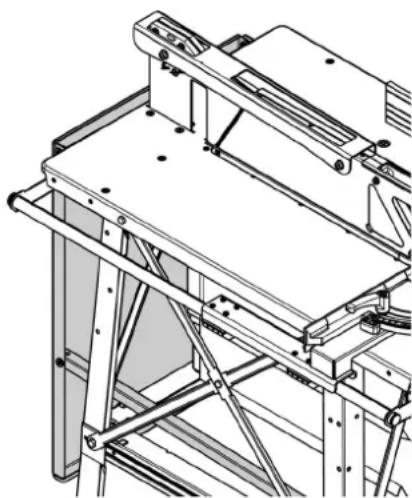
6.2 Table extension

Note:
The table extension supports must be firmly screwed to the saw table.
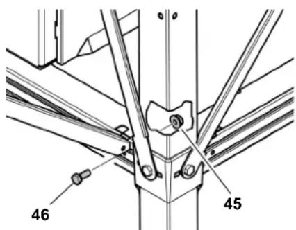
Screwing on the table extension
- Stick the angled ends of the supports into the slots in the crossstruts on the rear of the saw and push them outwards.
- Screw the supports to the strut using one hexagon head screw (46) and one hexagon nut (45) for each as illustrated.
Tightening the screwed connections
Check all screwed connections of the saw. Tighten the screwed connections hand-tight using a suitable tool.
When tightening the screws, bear in mind the following:
- The machine must be secure and horizontal after the screws have been tightened.
Aligning the table extension
- The surfaces of the table extension and saw table must both be in the same plane.
Swinging the table extension down
- Unscrew and remove the hexagon head screws (46) on both ends of the supports. Store the screws and nuts.
-
Slide the lower ends of the supports towards each other.
-
Unhook the supports and carefully swing the table extension down as illustrated. Set the table extension supports down on the lower cross-struts of the saw table.
6.3 Mains connection
Mains cable
- Make sure that the mains cable is out of the way so that it does not interfere with the work and cannot be damaged.
- Protect mains cable from heat, aggressive liquids and sharp edges.
- Connect the machine to the power supply using a suitable plug connection.
- Use only rubber-insulated extension cables with sufficient cross sections (see 'Technical Data').
- Do not pull on mains cord to unplug.

High voltage!
Operate saw in dry environment only.
Operate saw only on a power source matching the following requirements (see also 'Technical Data'):
- Outlets must be properly installed, earthed and tested.
- Outlets must have neutral wires for 3-phase DC.
-
The supply voltage and frequency must match the data given on the machine's nameplate.
Protection against electric shock by a residual current device (RCD) of 30mA sensitivity. -
Use a max. 16A mains fuse (short-circuit protection device) for short-circuit protection.
- Unplug the power plug from the outlet to disconnect it from the power supply.
i Note:
Please contact your Electricity Board or qualified electrician if you are unsure of whether your house supply fulfils these requirements.
i Note:
Due to the high start-up current of the motor during switch-on mains voltage fluctuations may occur - these can be recognised through, e.g., temporarily flickering lights. In this case the mains connection point has a higher impedance than the recommended maximum value (see 'Technical Data'). Please contact your Electricity Board or qualified electrician to have the connection point inspected.
#
Changing the direction of rota (only possible for version with motor)
Depending on the phase sequence it is possible that the motor will turn in the wrong direction. This can lead to the piece of wood being hurled away when an attempt is made to make a cut. Therefore the rotational direction must be checked every time the machine is connected to a different outlet.
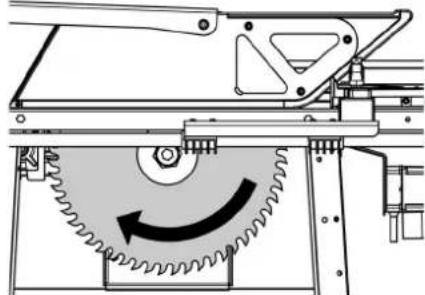
Checking the direction of rotation
- Install machine ready for work and connect it to the mains.
- Start machine and immediately turn OFF again.
i Note:
The humming noise after switch-off arises due to the electronic motor brake response. It is not a machine fault!
3. Check the saw blade's direction of rotation from the left-hand side of the saw. The saw blade must rotate clockwise.
If the saw blade rotates anti-clockwise:
Changing the direction of rotation
- Disconnect the mains cable from the machine.
- Using a screwdriver, press down the phase changer in the connector on the machine and rotate by 180^ .
Caution!
Do not attempt to turn the phase changer at the contact pins!

6.4 Chip and dust extraction unit
Danger!
The machine produces wood dust while working, so connect it to a dust collector.
Dust of certain timber species (e.g. beech, oak, ash) can cause cancer when inhaled.
- Use a suitable dust extraction unit when working in enclosed spaces.
- In addition, use a dust mask, as not all saw dust is collected or extracted.
- Operation without a suitable dust collector is only allowed out of doors.
The dust collector must fulfill the following requirements:
Matches the diameter of the dust suction nozzle (see available accessories chapter). Diameter 100mm
Air flow volume ≥ 460m^3/h
- Underpressure at the saw's suction nozzle ≥ 530Pa
Air speed at the saw's suction nozzle ≥ 20m / s
To connect the circular saw to a dust collector, you will need a dust suction nozzle (see available accessories chapter).
Switch on the dust collector before beginning sawing.
Observe the dust collector's operating instructions as well!
7. Operation
Risk of injury!
This saw may only be operated by one person at a time. Other persons shall stay only at a distance to the saw for the purpose of feeding or removing stock.
Before starting work, check to see that the following are in proper working order:
- mains cable and plug;
- ON/OFF switch;
- riving knife;
blade guard; and - feeding aids (push stick, handle for push block).
Use personal protection equipment:
- dust mask;
-ear protection; and - safety goggles.
Assume proper operating position:
- at the front of the saw on the operator side;
-in front of the saw;
to the left of the line of cut; and - if work is being carried out by two persons, with the other person remaining at an adequate distance to the saw.
If the type of work requires it, use the following:
- suitable workpiece supports - if otherwise workpiece would fall off the table after being cut
- dust extraction device (accessory).
Avoid typical operator mistakes:
- Do not attempt to stop the saw blade by pushing the workpiece against its side. This poses a risk of kickback.
-
Always hold the workpiece down on the table and do not jam it. This poses a risk of kickback.
-
Never cut several workpieces at the same time - and also never cut bundles containing several individual pieces. There is a risk of personal injury if individual pieces are caught by the saw blade in an uncontrolled manner.

Drawing-in/trapping hazard!
Never cut workpieces to which ropes, cords, bands, cables or wires are attached or workpieces which contain any of these materials.

Risk of injury!
Do not attempt to remove chips from the saw table while the saw blade is rotating. The saw blade must always be stationary before such work can be carried out.

Note:
During every cutting operation makesure the blade guard is covering the saw blade and the lower front edge of theblade guard is touching the workpiece.
7.1 Sawing with the rip fence
The fence extrusion of the rip fence must be adapted to the workpiece to be cut.
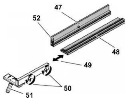
Adapting the rip fence to the workpiece height
- Undo the wing nuts (50) and remove the fence extrusion.
- Depending on the workpiece height, mount the high auxiliary fence (47) or the low auxiliary fence (48).
-
Fix the fence extrusion in place using the wing nuts (50).
-
Lock the rip fence in position with the lock lever (51).
Adapting the rip fence to the workpiece length
- Undo the wing nuts (50) and remove the fence extrusion.
- Adjust the fence extrusion in the longitudinal direction (49) for the workpiece length.
- Fix the fence extrusion in place using the wing nuts (50).
- Lock the rip fence in position with the lock lever (51).
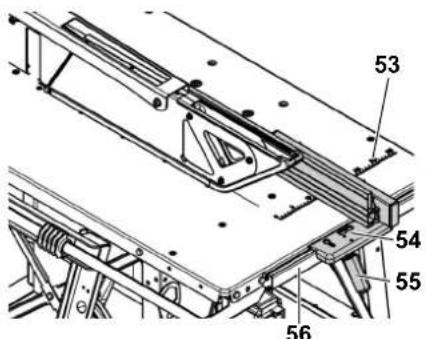
Sawing with the rip fence
- Lower the rip fence (54) onto the guide rail (56) on the front of the saw.
- Using the scale stamped on the saw table (53) set the distance from the rip fence to the saw blade.
- Lock the rip fence in position with the lock lever (55).

Always use the push stick if the distance between saw blade and rip fence is less than 120~mm

If the push stick is not needed it can be fastened via the clip (52) to the fence extrusion.
- Start motor.
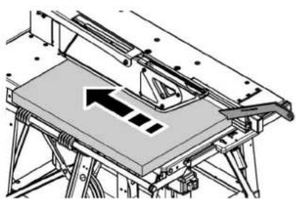
- Guide the workpiece slowly along the rip fence up to the saw blade and cut in a single pass.
- Turn machine off if no further cutting is to be done immediately afterwards.

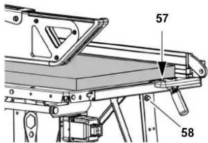
If you do not need the rip fence you can hang it via the hole (57) on the suspension bolt (58) on the front right table leg for easy access.
Setting the rip fence for ripping solid wood
- Set the rear end of the rip fence (59) at a position corresponding to the midpoint (61) between the saw spindle (60) and the saw blade tip (62).
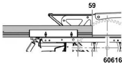


After every cutting operation use the push stick to guide the workpiece
carefully between the saw blade and the rip fence to the rear area of the saw table and remove it from the table.
Setting the rip fence for cutting boards
- Set the rear end of the rip fence (63) to the maximum possible length, or at least such that it is in line with the saw spindle (64).
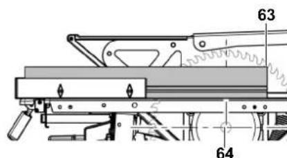
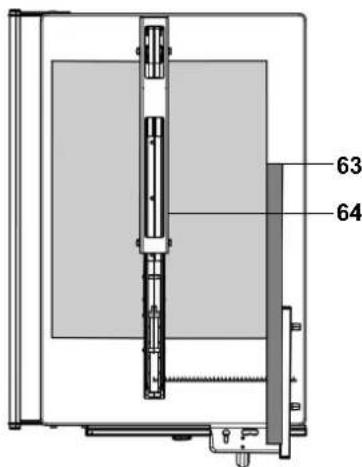
Caution!
After every cutting operation use the push stick to guide the workpiece carefully between the saw blade and the rip fence to the rear area of the saw table and remove it from the table.
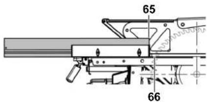
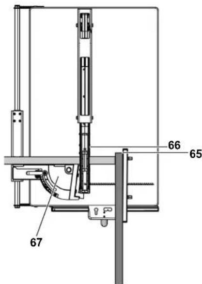
Setting the rip fence as a stock stop for cross-cutting
For cutting narrow workpieces you can use the rip fence as a stock stop.
- Fold the metre fence (67) out onto the table.
- Set the rear end of the rip fence (65) such that it is in line with the saw blade tip (66).
Danger!
If the workpiece is wedged it can be flung out uncontrolledly. Adjust the rip fence such that the workpiece ends are not simultaneously contacting the saw blade and the rip fence.
Caution!
After every cutting operation use the push stick to guide the workpiece carefully between the saw blade and the rip fence to the rear area of the saw table and remove it from the table.
7.2 Sawing with the mitre fence
- Swing mitre fence on the table top.
- Set the desired fence angle and fix in place with the lock lever (68). The metre fence can be adjusted by a maximum of 45^ for metre cuts.
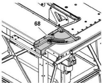
-
Start motor.
-
Guide the workpiece slowly with the mitre fence up to the saw blade and cut in a single pass.
- Turn machine off if no further cutting is to be done immediately afterwards.
i Note:
Fold down the mitre fence if you do not need it.
7.3 Cutting wedges
- Cut square or rectangular timber to the desired wedge length (see 'Sawing with the metre fence' and 'Sawing with the rip fence').
- Firmly press the workpiece into the wedge cutting jig (69).
- Start the machine.
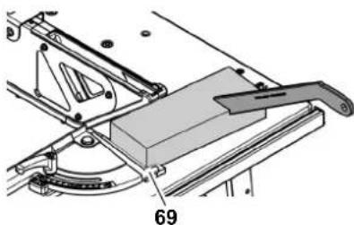
Danger!
During cutting of wedges there is an increased risk of injury due to the close proximity to the saw blade during the work. Only carry out the following step with the help of the push stick.
- Guide the workpiece slowly with the mitre fence up to the saw blade and cut in a single pass.
- Stop the machine and let the saw blade come to a stop.
- Retract the metre fence and remove the wedge.
8. Tips and tricks
- Before making a cut: make a trial cut on appropriate waste pieces.
Always lay the workpiece on the saw table such that it cannot tip over or wobble (e.g. place a curved board with the convex side up). - For long workpieces: use suitable workpiece supports, for example roller support or extension table (see 'Available Accessories').
- Keep surfaces of the table top and table extension clean - in particular, remove resin residue with a suitable cleaning and maintenance spray (optional accessory).
9. Care and maintenance

Danger!
Unplug before servicing.
Repair and maintenance work other than described in this section should only be carried out by qualified specialists.
Damaged parts, particularly safety devices, must only be replaced with genuine parts. Parts which have not been tested and released by the manufacturer can lead to unforeseen damage.
- Check that all safety devices are operational again after each service.
9.1 Changing the saw blade

Danger!
Directly after cutting the saw blade can be very hot - burn hazard! Let a hot saw blade cool down.
Do not clean the saw blade with combustible liquids.
Risk of injury, even with the blade at standstill. Wear gloves when changing blades.
When fitting a saw blade, observe the direction of rotation!
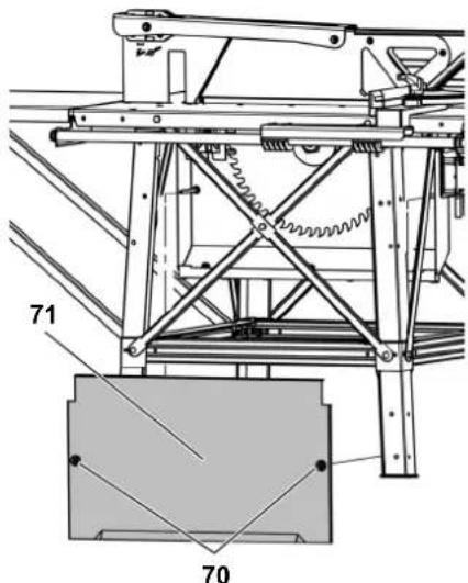
-
Remove the protective cover (71) from the chip case. To do so, carry out the following steps:
-
Loosen the hexagon screws (70) on the protective cover (71).
- Remove the protective cover, guide it out through the bottom and store.

Danger!
- Do not extend the tool for loosening the saw blade.
-
Do not loosen the arbor bolt by hitting the tool.
-
Remove the arbor bolt (72) on the saw blade mount using the spanner (left-hand thread!). Hold outer blade collar (74) with open-ended spanner to counter.
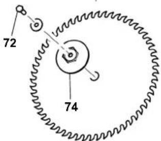
- Carefully take the outer blade collar (74) off the saw spindle. Hold the saw blade while doing so.
- Remove the saw blade from the saw spindle.
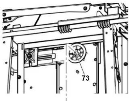
- Clean the saw blade, inner blade collar (73) and outer blade collar (74).

Danger!
Do not use any cleaning agents (e.g. to remove resin residue) which could attack the light metal components; otherwise the strength of the part could be lowered.
6. Put on a fresh saw blade (observe direction of rotation!).

Danger!
Use only saw blades meeting the requirements of EN 847-1 (see "Technical Specifications") - if unsuitable or damaged saw blades parts are used, parts can be ejected due to centrifugal force in an explosive-type manner.
Do not use:
-saw blades with maximum speed ratings lower than the saw spindle speed (see 'Technical Data');
-saw blades made of highstrength steel (HSS or HS);
-saw blades with visible damage or deformations;
-cut-off wheel blades.

Danger!
- Only install saw blade with genuine parts.
- Do not use any reduction rings; otherwise the saw blade could loosen.
Saw blades have to be installed in such way that they do not wobble or run out of balance and cannot work loose during operation.
- Attach the outer blade collar (74).
-BKS 450 Plus 5.5 DNB:
The two driver lugs on the outer blade collar must extend into the two cut-outs in the saw spindle.
- BKS 400 Plus 4.2 DNB:
The two driver lugs on the inner blade collar must extend into the two cut-outs in the outer blade collar.
Danger!
-
Do not extend the tool for tightening the arbor bolt.
-
Do not tighten the arbor bolt by hitting the wrench.
-
Screw the arbor bolt (72) on the saw blade mount into the saw spindle (left-hand thread!) and tighten. Hold outer blade collar (74) with ring spanner to counter.
-
Install the protective cover (76) on the chip case. To do so, carry out the following steps:
-
Insert the protective cover.
Screw in the hexagon nuts (75) on the protective cover (76).

9.2 Aligning the riving knife
Note: BKS (pre-assembled)
The riving knife has already been aligned to the saw blade in the factory. However, it is still necessary to check the distance from the riving knife to the saw blade and if necessary align the knife at regular intervals.
To align the riving knife:
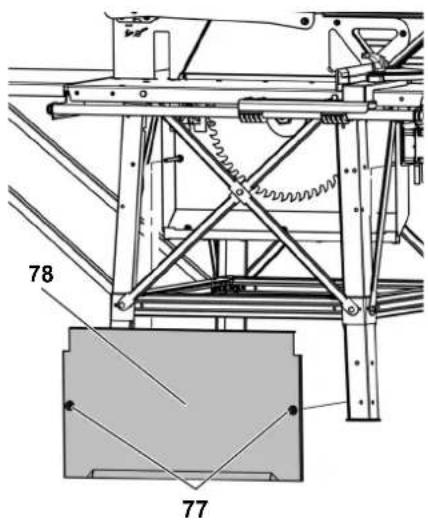
-
Remove the protective cover (78) from the chip case. To do so, carry out the following steps:
-
Remove the hexagon nuts (77) from the protective cover and store.
Take off the protective cover, guide it out through the bottom and store.
Adjusting the distance from the riving knife to the saw blade
The distance between the saw blade's outer edge and the riving knife shall be between 3 and 8mm
The riving knife must project over the saw table at least as far as the saw blade does.
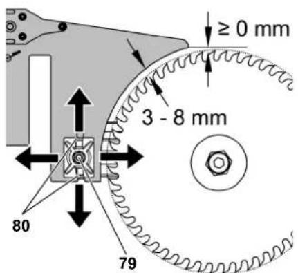
- Loosen the Keps nut (79) on the riv- ing knife carrier one full turn.
- Adjust the distance from the riving knife to the saw blade.
- Adapt the riving knife height to the saw blade.

Note:
When tightening the Keps nut makes sure the two lugs (80) on the counterpart of the riving knife carrier are running in the tracks of the riving knife carrier.
- Tighten the Keps nut.
After aligning re-install the protective cover on the chip case.
9.3 Saw storage

Danger!
Store saw so that
- it cannot be started by unauthorised persons and
- nobody can get injured.

Caution!
Do not store saw unprotected outdoors or in damp environment.
9.4 Maintenance
Before switching ON
- Carry out a visual inspection to determine whether the distance between the saw blade and the riving knife is 3 to 8 mm.
- Carry out a visual inspection to determine whether the saw blade is lined up with the riving knife.
- Check to ensure the power cable and plug are undamaged. Have defective parts replaced by an electrician.
After switching OFF
Check whether the saw blade keeps running for more than 10 seconds after switch-off. If so, contact a certified garage!
Daily (BKS 450 Plus only)
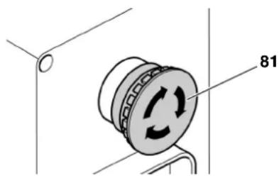
- Check to ensure the emergency off switch (81) functions properly. Do not use the tool if the emergency off switch is defective. Have a defective emergency off switch repaired by a qualified electrician.
Once a month (for daily use)
- Remove sawdust with vacuum cleaner or brush.
-Oil the metre fence guide.
After every 300 hours of operation
Check all screwed connections and retighten if necessary.
10. Transport
- Remove or secure add-on parts (length stop and rip fence, sliding carriage, table extension).
- If possible, use the original cardboard box for shipping.
Hoisting by crane
For hoisting by crane use the flip-up crane lifting eyes on the saw table.

Danger!
During hoisting by crane moving parts such as the rip fence, ring spanner or the like can loosen and fall off.
Remove or secure moving and loose add-on parts before transport.
11. Available Accessories
For special tasks the following accessories are available at your specialised dealer - see back cover for illustrations:
A Roller Stand RS 420
B Dust Extraction Port Diameter: 100mm for connection of site saw to a dust extractor.
C Care and Maintenance Spray For removing resin residue and preserving metal surfaces.
D Saw Blade CV 400 × 2 × 30 56 coarse teeth for fast rough rip- ping and cross-cutting of softwood.
E Saw Blade HM 400 × 3.5 × 30 28 square teeth bevelled for tough work, construction timber, shuttering boards, waste concrete, gas concrete and particle board.
F Saw Blade HM 400 × 3.5 × 30 60 alternate top bevel teeth for solid wood, rip cuts and cross-cuts.
G Saw Blade HM 450 × 3.8 × 30 66 alternate top bevel teeth for solid wood, rip cuts and cross-cuts.
H Saw Blade HM 450 × 3.5 × 30 32 square teeth bevelled for tough work, construction timber, shuttering boards, waste concrete, gas concrete and particle board.
12. Repair
Danger!
Have your power tool serviced by a qualified repair person using only identical replacement parts. This will ensure that the safety of the power tool is maintained.
Contact your local Metabo representative if you have Metabo power tools requiring repairs. See www.metabo.com for addresses.
You can download a list of spare parts from www.metabo.com.
13. Protection of the Environment
The machine's packing can be 100% recycled.
End-of-life power tools and accessories contain large amounts of valuable raw materials and plastics which must be recycled.
This manual was printed on chlorine-free bleached paper.
14. Troubleshooting
Danger!
Before carrying out any fault servicing, always do the following:
- Switch machine OFF.
- Unplug mains cable.
- Wait for saw blade to come to standstill.
Check to see that all safety devices are operational after each fault service.
Motor does not run
Undervoltage relay tripped by power failure:
-switch on again.
No mains voltage
- check cable, plug, outlet and mains fuse.
Motor overheated, e.g. by a blunt saw blade or chip build-up in the chip case:
- remove cause for overheating, wait for a few minutes, then start saw again.
Motor supply voltage too low:
- use a shorter supply line or a supply line with a larger cross section (≥ 2.5mm^2) .
have power supply checked by a qualified electrician.
Loss of cutting performance
Blunt saw blade (saw blade or workpiece possibly has burn marks on the surface):
- replace saw blade (see section 'Care and Maintenance').
Saw dust build-up
No or too weak dust collector connected:
connect a dust extraction port (see 'Available Accessories') and dust collector or
- increase suction power of the dust collector.
15. Technical Data
| BKS 400 Plus 4.2 DNB | BKS 450 Plus 5.5 DNB | ||
| Voltage | V | 400 / (3~50 Hz) | 400 / (3~50 Hz) |
| Nominal current A 7.2 7.5 | |||
| Fuse protection min. A 16 16 | |||
| Protection class | IP 54 | IP 54 | |
| Motor speed min | -1 | 2750 2800 | |
| Motor capacity | |||
| Power input P1 | kW | 4.2 kW S6 40% | 5.5 kW S6 40% |
| Power output P2 | kW | 3.25 kW S6 40% | 3.2 kW S1 100% |
| Maximum mains impedance | Ohm | - | 0.25 |
| Saw blade cutting speed approx. | m/s | 58 | 66 |
| Riving knife thickness | mm | 3.0 | 3.0 |
| Saw blade | |||
| saw blade diameter (outer) | mm | 400 | 400 |
| saw blade hole (inside) | mm | 30 | 30 |
| cutting width | mm | >3.2 | >3.2 |
| max. base body thickness of the saw blade | mm | ≤2.8 | ≤2.8 |
| Cutting depth | mm | 127 | 140 |
| Dimensions | |||
| Saw table length | mm | 1030 | 1030 |
| Saw table width | mm | 660 | 660 |
| Table extension length | mm | 800 | 800 |
| Table extension width | mm | 500 | 500 |
| Height (saw table) | mm | 850 | 850 |
| Height (overall) | mm | 1020 | 1020 |
| Weight (complete approx.) | kg | 88 | 94 |
| Guaranteed sound power level according to DIN EN ISO 19085-10* (LWA(G)) | dB (A) | 109 | 109 |
| Sound pressure level according to DIN EN ISO 19085-10* | |||
| Measurement method: under load | |||
| Pressure level at operator's ear | dB (A) | 88 | 88 |
| Uncertainty K | dB (A) | 4 | 4 |
| Ambient temperature range | °C | -10 to +40 | -10 to +40 |
- The values stated are emission values and as such do not necessarily constitute values which are safe for the workplace. Although there is a correlation between emission levels and environmental impact levels, whether further precautions are necessary cannot be derived from this. Factors influencing the actually present environmental impact level in the workplace include the characteristics of the work area and other noise sources, i.e. the number of machines and other neighbouring work processes. The permitted workplace values can likewise vary from country to country. This information is intended to assist the user in estimating hazards and risks.
- Overview of the Saw
- Table of Contents
- Please Read First!
- Danger!
- Risk of electric shock!
- Drawing-in/trapping hazard!
- Caution!
- Note:
- Safety Instructions
- Specified conditions of use
- General safety instructions
- General hazards!
- Danger! Risk of electric shock!
- Risk of personal injury and crushing by moving parts!
- Cutting hazard, even with the cutting tool at standstill!
- Risk of kickback (workpiece is caught by the saw blade and thrown against the operator)!
- Danger due to insufficient perprotection equipment!
- Risk of injury by inhaling dust!
- Hazard caused by modifica- of the machine or use of parts
- not tested and approved by the manufacturer!
- Hazard caused by machines!
- Risk of injury by noise!
- Danger from blocking work- s or workpiece parts!
- Symbols on the machine
- Data on the nameplate
- Symbols on the machine
- Safety devices
- Riving knife
- Blade guard
- Push stick
- Handle for push block
- Special Product Features
- Operating elements
- Emergency off switch (BKS 450 Plus only)
- ON/OFF switch
- i Note:
- Fences
- Set-up
- Setting up the machine
- Table extension
- Screwing on the table extension
- Tightening the screwed connections
- Aligning the table extension
- Swinging the table extension down
- Mains connection
- Mains cable
- High voltage!
- #
- Checking the direction of rotation
- Changing the direction of rotation
- Chip and dust extraction unit
- Operation
- Risk of injury!
- Use personal protection equipment:
- Assume proper operating position:
- If the type of work requires it, use the following:
- Avoid typical operator mistakes:
- Sawing with the rip fence
- Adapting the rip fence to the workpiece height
- Adapting the rip fence to the workpiece length
- Sawing with the rip fence
- Setting the rip fence for ripping solid wood
- Setting the rip fence for cutting boards
- Setting the rip fence as a stock stop for cross-cutting
- Sawing with the mitre fence
- Cutting wedges
- Tips and tricks
- Care and maintenance
- Changing the saw blade
- Do not use:
- Aligning the riving knife
- Note: BKS (pre-assembled)
- Adjusting the distance from the riving knife to the saw blade
- Saw storage
- Maintenance
- Before switching ON
- After switching OFF
- Daily (BKS 450 Plus only)
- Once a month (for daily use)
- After every 300 hours of operation
- Transport
- Hoisting by crane
- Available Accessories
- Repair
- Protection of the Environment
- Troubleshooting
- Motor does not run
- Loss of cutting performance
- Saw dust build-up
- Technical Data
Brand : METABO
Model : BKS 450 Plus
Category : Motorcycle