PKF 255 - Saw METABO - Free user manual and instructions
Find the device manual for free PKF 255 METABO in PDF.
Download the instructions for your Saw in PDF format for free! Find your manual PKF 255 - METABO and take your electronic device back in hand. On this page are published all the documents necessary for the use of your device. PKF 255 by METABO.
USER MANUAL PKF 255 METABO
Assembly instructions Transversing saddle
Monteringsanvisning Tvärvagn 115 164 4518 GB/F/N/SF/S 4505 2.0G Retain proof of purchase! You are only entitled to claim warranty against proof of purchase.
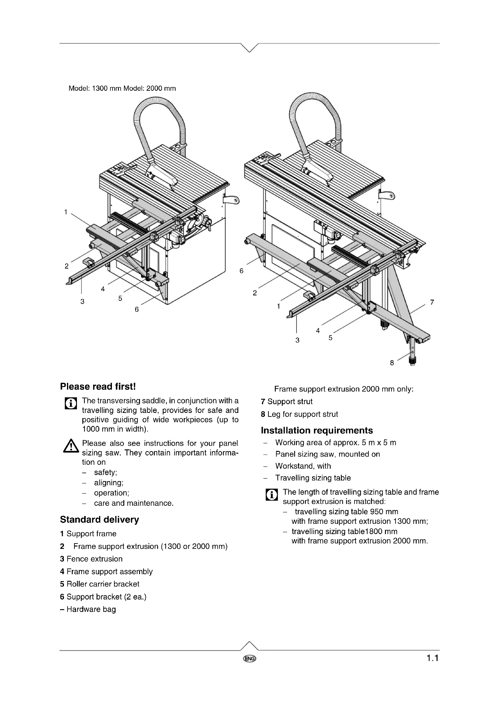
The transversing saddle, in conjunction with a travelling sizing table, provides for safe and positive guiding of wide workpieces (up to 1000 mm in width).
Please also see instructions for your panel sizing saw. They contain important informa- tion on − safety; − aligning; − operation; − care and maintenance. Standard delivery Installation requirements − Working area of approx. 5 m x 5 m − Panel sizing saw, mounted on − Workstand, with − Travelling sizing table
The length of travelling sizing table and frame support extrusion is matched: − travelling sizing table 950 mm with frame support extrusion 1300 mm; − travelling sizing table1800 mm with frame support extrusion 2000 mm. 1 Support frame 2 Frame support extrusion (1300 or 2000 mm) 3 Fence extrusion 4 Frame support assembly 5 Roller carrier bracket 6 Support bracket (2 ea.) – Hardware bag
Model: 1300 mm Model: 2000 mm Frame support extrusion 2000 mm only: 7 Support strut 8 Leg for support strut ZA0002E2.fm 1Great Britain1.2 Installation variations The transversing saddle’s fence extrusion can be installed relevant to the job:
- Workpiece shall rest with its front edge (= the edge closest to the operator) against the fence extrusion (fig. 1): − Fence extrusion is installed on the front edge of the travelling sizing table; − Travelling sizing table and frame support extrusion are installed as far forward as pos- sible.
Hint: This mounting version is not possible in con- nection with UTENSILO 4 (drawers may not be opened).
- Workpiece shall rest with its rear edge (= the edge most distant from the operator) against the fence extrusion (fig. 2): − Install fence extrusion on rear edge of travel- ling sizing table; − Travelling sizing table and frame support extrusion are installed as much to the rear as possible. Installing the frame support extrusion
1. Fit both support brackets to the machine’s work-
stand, using the screws, nuts, and washers of the workstand.
2. Screw a hexagon nut M 8 for about 15 mm on a
hexagon head screw M 8x40.
3. Fit hexagon head screw with nut as shown into
the upper hole of the support bracket and secure with a hexagon nut M 8.
4. Repeat steps 2 and 3 on other support bracket.
5. Place frame support extrusion on support brak-
kets, and slide two cup square neck screws M 8x20 into the groove.
6. Put each cup square neck screw (grey arrow)
from the top through the oblong hole in the sup- port brackets. Fit a washer to each screw and screw on a starknob. Do not yet tighten the star- knob.
7. Fit one washer and rubber buffer (black arrow)
to each M 6x40 hexagon head screw. Put the so prepared screws into the holes at each end of the frame support extrusion, secure with hexa- gon nuts M 6.
port extrusion: it should project an equal distance over the machine housing at both front and rear.
9. Tighten both starknobs on the support brackets.
10. Attach one endplate to each end of the frame
support extrusion. Frame support extrusion 2000 mm: The 2000 mm frame support extrusion is fastened with an additional support strut to the workstand. The support strut is installed to that side of the work- stand at which the frame support extrusion projects the most (see above). The installation to the front of the saw is described below:
11. Fit each bracket with two cup square neck
screws M 8x45, washers and hexagon nuts to the support strut’s leg.
12. Slide two square nuts M 8 into the two grooves
of the support strut.
13. Attach the support leg bracket with two hexagon
head screws M 8x16 and washers at the end of the support strut, where the hole is located.
14. Fit appropriate bracket with two hexagon head
screws M 8x30, washers and square nuts M 8 to other end of the support strut.
Only one of the two brackets is required. Save the other bracket in case the travelling sizing table is to be shifted to the rear of the saw.
15. Screw support strut with the bracket to the work-
stand. To do so, use screw, nut and washer from the workstand.
16. Fit a cup square neck screw M 6x50 as shown
into groove of frame support extrusion.
17. Screw the foot end of the support strut with was-
her and nut to the cup square neck screw in the frame support extrusion. Adjust height with the adjustable foot assembly on the support strut leg.1.4
18. Screw an endplate to each end of the frame
support extrusion and affix the yellow-black warning labels to the projecting ends so that they are clearly visible.
19. Tighten both starknobs on the support brackets.
Assembling the support frame
1. Place pre-assembled support frame with scales
facing down on a level surface.
2. Attach the triangular frame support assembly,
using the pre-installed screws, matching was- hers and nuts to the support frame’s centre.
3. Install roller with bush as shown on the frame
support assembly with hexagon head screw M 8x35 and hexagon nut M 8.
4. Fit second roller likewise to the roller carrier
5. Attach roller carrier bracket with four hexagon
head screws M 8x16 and four hexagon flange nuts M 8 to frame support assembly. Attaching the transversing saddle
1. Turn transversing saddle over so that the sup-
port frame is at the top.
2. Slightly loosen the two ratchet lock levers
(arrows) on the support frame .
3. Slide support frame with slide rail into the travel-
ling sizing table’s upper groove.
4. Move transversing saddle to desired position
and tighten both ratchet lock levers. Aligning the frame support extrusion
Before the frame support extrusion can be ali- gned, the travelling sizing table has to be pro- perly aligned (see installation instructions for travelling sizing table). Firstly the height of the frame support extrusion is aligned :
1. Slightly loosen support brackets on workstand.
2. Adjust height of support brackets (to lift up use a
batten as lever, if necessary). The frame sup- port extrusion needs to be aligned so that, wit- hout load, the upper roller (arrow) touches the extrusion without pressure.
3. Tighten both support brackets.
After setting the frame support extrusion in height its lateral alignment is set:1.5
1. Slightly loosen both starknobs on support brak-
2. Loosen counter nuts M 8 of the support brackets
3. Adjust set screws. The frame support extrusion
must be lined up over its entire length so that the upper surfaces of support frame and travelling sizing table are level with each other in any posi- tion (use spirit level or steel straight edge to check).
4. Tighten counter nuts on set screws.
5. Tighten starknobs on support brackets.
The mitre fence extrusion is held by two guide elements. The position of the guide elements can be changed depending on the desired angle: For angles ≤ 90° the right-hand guide ele- ment is attached to the front receiver of the support frame. For angles ≥ 90° the right-hand guide ele- ment is attached to the rear receiver of the support frame.
1. Insert pivot bolt from the top into one of the two
receivers of the support frame.
2. Screw a starknob screw with spacer bush from
below into the pivot bolt; – do not yet tighten the starknob screw.
3. Put a washer on the threaded end of the male
ratchet lock lever. Insert ratchet lock lever from top into a hole in the guide element.
4. Screw ratchet lock lever into pivot bolt; – do not
5. Fit guide plate to a cup square neck screw
6. Fit cup square neck screw from underside into
hole of a guide element.
7. Slide guide element with cup square neck screw
into groove of the support frame’s centre extrusion.
8. Fit washer on cup square neck screw and screw
on the female ratchet lock lever; – do not yet tighten.
9. Remove an endplate from the mitre fence
extrusion, and slide two cup square neck screws M 6x45 into the fence extrusion’s groove. 0°-45° 45°-0° Bild 181.6
10. Screw mitre fence extrusion with cup square
neck screws, washers and starknobs to the sides of the guide elements.
11. Fit a cup square neck screw M 6x20 to flipstop
guide plate and slide guide plate into the upper slot of the mitre fence extrusion.
12. Put flipstop onto threads of the cup square neck
screw and secure as shown.
13. Put the end plate removed earlier back to the
mitre fence extrusion and secure with a counter- sunk head tapping screw.
14. To set the mitre fence:
− set to required angle; − tighten all three ratchet lock levers; − tighten both starknobs. Setting the scales
1. Use try square to set mitre fence extrusion
square against the line of cut.
2. Tighten ratchet lock levers and starknobs.
3. Loosen scale fixing screw.
4. Adjust scale so that the "0" mark is exactly under
the front edge of the mitre fence extrusion.
5. Tighten scale fixing screw.
6. Swing stop plate towards mitre fence extrusion.
7. Loosen set screw counter nuts and fit set screw
so that it just touches the mitre fence extrusion (arrow).