
UK 290 - Saw METABO - Free user manual and instructions
Find the device manual for free UK 290 METABO in PDF.
| Product type | Table saw / sliding saw |
| Brand | Metabo |
| Model | UK 290 |
| Table dimensions (L x W) | 674 x 478 mm |
| Height (frame unfolded) | 878 mm |
| Height (frame folded) | 420 mm |
| Weight | 25 kg |
| Supply voltage | 230 V ~ 50 Hz |
| Power consumption (P1) | 1.8 kW |
| Useful power (P2) | 1.3 kW |
| Rated current | 8.8 A |
| Recommended fuse | 10 A |
| No-load speed | 5000 min⁻¹ |
| Max. cutting speed | 57 m/s |
| Saw blade diameter | 210 - 220 mm |
| Blade bore | 30 mm |
| Cutting width (kerf) | 2.4 - 2.6 mm |
| Max. blade body thickness | 1.7 mm |
| Cutting height at 0° | 60 mm |
| Cutting height at 45° | 42 mm |
| Max. travel length | 295 mm |
| Blade tilt | -1.5° to 46.5° |
| Riving knife thickness | 1.8 mm |
| Sound pressure level (no-load) | 85 dB(A) |
| Sound power level (no-load) | 96 dB(A) |
| Sound pressure level (cutting) | 87 dB(A) |
| Sound power level (cutting) | 101 dB(A) |
| Extraction diameter (hood) | 38 mm |
| Extraction diameter (housing) | 58/43 mm |
| Required air flow | ≥ 460 m³/h |
| Required vacuum | ≥ 530 Pa |
| Required air velocity | ≥ 20 m/s |
| Protection rating | IP20 |
Frequently Asked Questions - UK 290 METABO
User questions about UK 290 METABO
0 question about this device. Answer the ones you know or ask your own.
Ask a new question about this device
Download the instructions for your Saw in PDF format for free! Find your manual UK 290 - METABO and take your electronic device back in hand. On this page are published all the documents necessary for the use of your device. UK 290 by METABO.
USER MANUAL UK 290 METABO
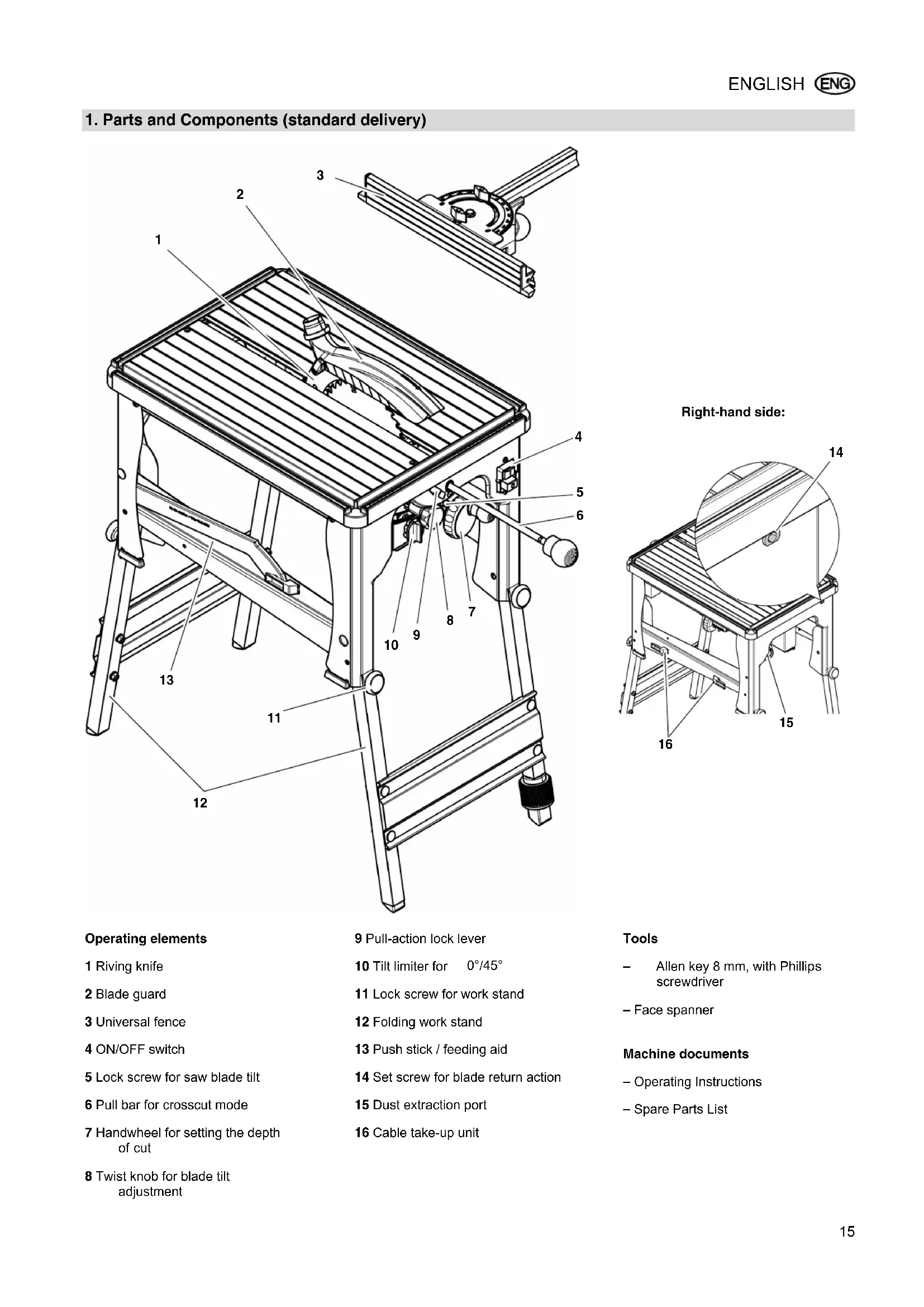
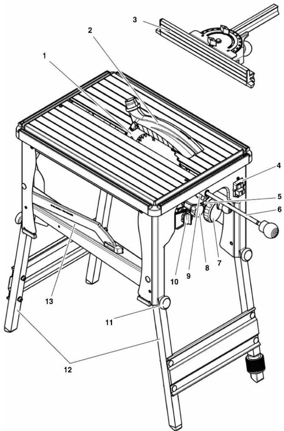
1. Parts and Components (standard delivery)
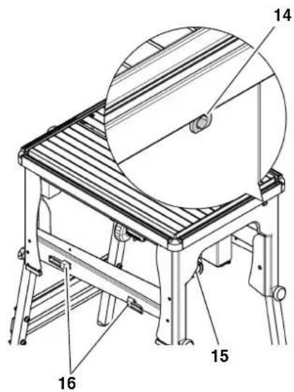
Right-hand side:
Operating elements
1 Riving knife
2 Blade guard
3 Universal fence
4 ON/OFF switch
5 Lock screw for saw blade tilt
6 Pull bar for crosscut mode
7 Handwheel for setting the depth of cut
8 Twist knob for blade tilt adjustment
9 Pull-action lock lever
10 Tilt limiter for 0° / 45°
11 Lock screw for work stand
12 Folding work stand
13 Push stick / feeding aid
14 Set screw for blade return action
15 Dust extraction port
16 Cable take-up unit
Tools
Allen key 8 mm, with Phillips screwdriver
-Face spanner
Machine documents
- Operating Instructions
- Spare Parts List
Table of Contents
- Parts and Components (standard delivery) 15
- Please Read First! 16
- Safety 16
3.1 Specified Conditions of Use 16
3.2 General Safety Instructions...16
3.3 Symbols on the machine.. 17
3.4 Safety Devices 18 - Special Product Features 18
- Operating Elements 18
- Initial Operation.. 19
6.1 Machine Installation 19
6.2 Dust Collector 20
6.3 Mains Connection 20 - Operation 21
7.1 Circular Saw. 21
7.2 Crosscut Saw 21 - Care and Maintenance.. 22
8.1 Saw Blade Change 22
8.2 Adjusting the Scale 23
8.3 Adjusting the Tilt Limiter 23
8.4 Setting the Motorhead Carriage Damper 23
8.5 Cleaning the Saw.. 23
8.6 Storage 23
8.7 Maintenance 23 - Transport 23
- Tips and Tricks 24
- Available Accessories 24
- Repairs 24
- Environmental Protection ....24
- Trouble Shooting 24
- Technical Specifications 25
2. Please Read First!
These Operating Instructions have been written to make it easier for you, the user, to learn how to operate this machine and to do so safely. These instructions should be used as follows:
- Read these instructions before use. Pay special attention to and always follow all safety instructions.
These instructions are intended for persons with basic technical knowledge regarding the operation of a machine like the one described herein. If you have no experience whatsoever, you are strongly advised to seek competent advise and guidance from an experienced person before operating this machine. - Keep all documents supplied with this machine for future reference. Retain proof of purchase in case of warranty claims.
If you lend or sell this machine be sure to have these Operating Instructions go with it.
The manufacturer is not liable for any damage resulting from neglect of these Operating Instructions.
Information in these instructions is designated as under:
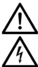
Danger! Risk of personal injury or environmental damage.
Risk of electric shock! Risk of personal injury by electric shock.
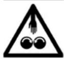
Drawing-in/trapping hazard! Risk of personal injury by body parts or clothing being drawn into the rotating saw blade.
Caution! Risk of material damage.

Note: Additional information.

Numbers in illustrations (1, 2, 3, ...)
indicate component parts;
are consecutively numbered;
correspond with the number(s) in brackets (1), (2), (3) ... in the neighbouring text.
- Numbered steps must be carried out in sequence.
- Instructions which can be carried out in any order are indicated by a bullet point () .
- Listings are indicated by a dash (-).
3. Safety
3.1 Specified Conditions of Use
This saw is intended for rip and cross cuts in solid wood, faced boards, chip board and wood-core plywood sheets and plastics.
Do not cut round stock without suitable jigs or fixtures. The rotating saw blade could turn the workpiece.
When sawing thin stock layed on edge, a suitable guide must be used for firm support.
Use of wobble saw blades is not permitted on this machine.
The tool must not be used for seaming, grooving and insert cutting (grooves that end within the workpiece).
Any use other than the use specified above is not allowed. Use other then specified, any alteration, modification or use of parts not approved by the manufacturer can cause unforeseeable damage!
3.2 General Safety Instructions
- When operating this machine observe the following safety instructions, to exclude the risk of personal injury or material damage.
- Please also observe the special safety instructions in the respective chapters.
- Where applicable, follow the legal directives or regulations for the prevention of accidents pertaining to the use of circular saws.

General hazards!
- Keep your work area tidy - a messy work area invites accidents.
- Be alert. Know what you are doing. Set out to work with reason. Do not operate machine while under the influence of drugs, alcohol or medication.
- Consider environmental conditions: keep work area well lighted.
- Prevent adverse body positions. Ensure firm footing and keep your balance at all times.
- Use suitable workpiece supports when cutting long stock.
- Do not operate the machine near inflammable liquids or gases.
- The saw shall only be started and operated by persons familiar with circular saws and being aware of the dangers associated with the operation of a circular saw. Persons under 18 years of age shall use this machine only in the course of their vocational training, under the supervision of an instructor.
- Keep bystanders, particularly children, out of the danger zone. Do not permit bystanders to touch the machine or power cable while it is running.
- Do not overload machine - use it only within the performance range it was designed for (see "Technical Specifications").

Danger! Risk of electric shock!
- Do not expose machine to rain.
- Do not operate machine in damp or wet environment.
- Prevent body contact with earthed objects such as radiators, pipes,
cooking stoves, refrigerators when operating this machine.
- Do not use the power cable for purposes it is not intended for.
Risk of personal injury and crushing by moving parts!
- Do not operate the machine without installed guards.
Always keep sufficient distance to the saw blade. Use suitable feeding aids, if necessary. Keep sufficient distance to driven components when operating the electric machine. - Wait for the saw blade to come to a complete standstill before removing cutoffs, scrap, etc., from the work area.
- Never try to slow down or stop the saw blade by pushing the workpiece against the saw blade from the side.
- Ensure the machine is disconnected from power before servicing.
- Ensure that when switching on (e.g. after servicing) no tools or loose parts are left on or in the machine.
- Turn power off if the machine is not used.
Cutting hazard, even with the cutting tool at standstill!
- Wear gloves when changing cutting tools.
- Store the saw blade(s) in a safe place and in such a manner that nobody can get hurt.
Risk of kickback (workpiece is caught by the saw blade and thrown against the operator):
Always work with a properly set riv- ing knife.
- The riving knife and the saw blade used must match: the riving knife should be thinner than the kerf, but thicker than the saw blade body.
- Do not jam workpieces.
Make sure the saw blade is suitable for the workpiece material.
Cut thin or thin-walled workpieces only with fine-toothed saw blades.
Always use sharp saw blades.
If in doubt, check workpiece for inclusion of foreign matter (e.g. nails or screws).
- Cut only workpieces that have dimensions which allow them to be safely and securely held during cutting.
- Never cut several workpieces at the same time – and also no bundles
containing several individual pieces. Risk of personal injury if individual pieces are caught by the saw blade uncontrolled.
- Remove small cutoffs, scrap, etc., from the work area - when doing so, the saw blade must be at a complete standstill.
Drawing-in/trapping hazard!
- Ensure that no parts of the body or clothing can be caught and drawn in by rotating components (no neckties, no gloves, no loose-fitting clothes; contain long hair with hair-net).
-
Never cut any workpieces which contain
-
rques,
strings,
-cods, - cables or
- wires, or to which any of the above are attached.
Hazard generated by insufficient personal protection gear!
- Wear hearing protection.
- Wear safety glasses.
- Wear dust mask.
- Wear suitable work clothes.
- When working outdoors wearing of non-slip shoes is recommended.
Risk of injury by inhaled wood dust!
- Some types of wood dust (e.g. beech, oak, ash) may cause cancer when inhaled. Work only with a suitable dust collector attached to the saw. The dust collector must comply with the specifications stated in the Technical Specifications.
Minimise the amount of wood dust escaping from the machine into the environs:
remove wood dust deposits from the work area (do not blow away!);
- repair any leakson the dust collector;
- keep your work area well ventilated at all times.
Hazard generated by modification of the machine or use of parts not tested and approved by the manufacturer!
- Strictly follow these instructions when assembling the machine.
-
Use only parts approved by the manufacturer. This applies especially to:
-
saw blades (see "Available Accessories" for stock-nos.)
-
safety devices (see "Spare parts list" for stock nos.).
-
Do not change any parts.
Hazard generated by tool defects!
- Keep machine and accessories in good repair. Follow the maintenance instructions.
- Before every use of this machine, check for possible damage: before operating the machine all safety devices, protective guards or slightly damaged parts need to be carefully checked to see if they are fully operational as specified. Check that all moving parts operate smoothly and without jamming. All parts must be correctly installed and meet all conditions necessary for a proper operation of the machine.
- An y damaged parts or protection devices must be repaired or replaced by a qualified specialist. Have damaged switches replaced by a service centre. Do not operate machine if the switch cannot be turned ON or OFF.
Keep handles free of oil and grease.
Risk of injury by noise!
- Wear hearing protection.
Make sure the riving knife is not bend. A bent riving knife will push the workpiece against the side of the saw blade, causing noise.
Danger from blocking workpieces or workpiece parts!
If blockage occurs:
- Switch machine OFF.
- Unplug mains cable.
- Wear gloves.
- Clear the blockage using a suitable tool.
3.3 Symbols on the machine

Danger!
Disregard of the following warnings may lead to serious personal injury or material damage.

Read instructions.

Do not reach into the revolving saw blade.

Wear safety goggles.

Wear hearing protection.
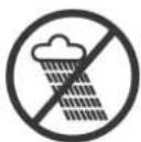
Do not operate machine in damp or wet environment.
When operated as circular saw the saw blade is arrested in the table's centre, for adjustments it is arrested in the forward position.
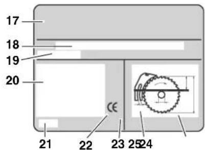
Information on the nameplate:
(17) Manufacturer
(18) Serial number
(19) Machine designation
(20) Motor specifications (see also "Technical Specifications")
(21) Date of manufacture
(22) CE-mark - indicating that this machine conforms to the EC directives as per Declaration of Conformity
(23) Waste disposal symbol - machine can be disposed of by returning it to the manufacturer
(24) Riving knife dimensions
(25) Dimensions of permissible saw blades
3.4 Safety Devices
Blade guard
The blade guard (26) protects against accidental contact with the saw blade, and from chips flying about.
Always have the blade guard installed during operation.
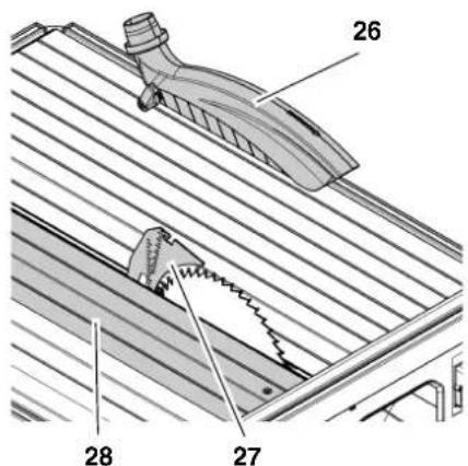
Riving knife
The riving knife (27) prevents the workpiece from being caught by the rising teeth of the saw blade, and being thrown back against the operator.
Always have the riving knife installed during operation.
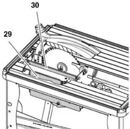
Contact protection
The following components protect against accidental contact with the saw blade:
Table insert extrusion (28),
- Chipcase cover plate (29),
- Contact guard (30)
These components must always be installed while the saw is operated.
Push stick
The push stick (31) serves as an extension of the hand and protects against accidental contact with the saw blade. Use push stick if distance rip fence - saw blade is ≤ 120mm .
Guide the push stick at an angle of 20° ... 30° against the saw table's surface.
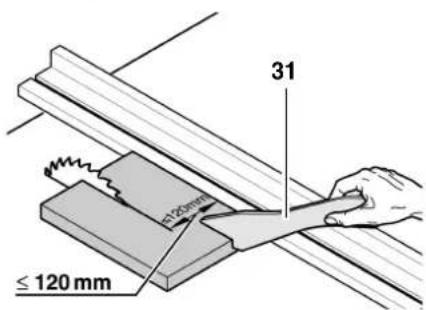
When the push stick is not used, it can be hung to the holder provided at the base's side.
Replace push stick if damaged.
4. Special Product Features
Radial pull action for precision cuts.
- Precision adjustable bevel tilt from -1.5° to 46.5° .
- Continuously adjustable depth of cut 0 - 60 mm.
All operating elements are located at the machine's front.
Electronic speed control:
motorsoftstart;
low mairs supply load;
constant saw blade speed, irrespective of load, provides for consistent cut quality;
- An electronic motor protection by overcurrent detection shuts the motor off when it is locked (e.g. by a blocked saw blade).
- An undervoltage relay prevents the machine from starting up when power is restored after a power failure.
- Compact design for quick and easy transportation.
- Folding work stand - perfect for on-site use.
Universal fence is standard delivery.
5. Operating Elements
ON/OFF switch
To turn ON = press green switch button (32).
To turn OFF= press red switch button (33).
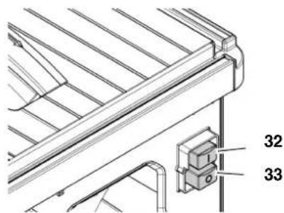

Note:
In case of a voltage loss a no-voltage release relay will trip. This prevents the starting of the machine when the power is restored. To restart, press the Start button.
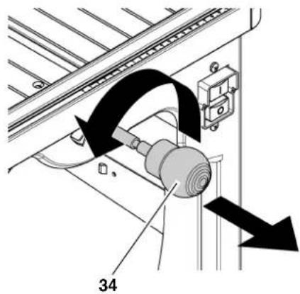
Pull bar for crosscut mode
In crosscut mode the saw blade is pulled forward with the pull bar:
- Turn knob (34) counter-clockwise: saw blade can now be moved lengthwise by pulling on the knob. When the knob (34) is released, the saw blade returns automatically to its rear stop position. At the stop position the pull bar is automatically arrested.
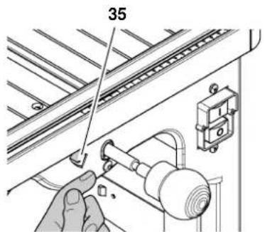
Pull action lock lever
To arrest the pull bar:
- Slide lever (35) to the left = pull bar is arrested at the front or centre position.
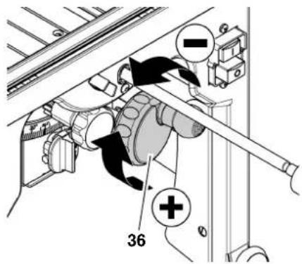
Handwheel for setting the depth of cut
The depth of cut can be adjusted by turning the handwheel (36).
Twist knob for blade tilt
With the twist knob (37) the saw blade can be continuously tilted from 0° through 45° .
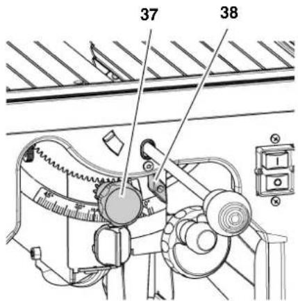
Lock screw
To keep the set bevel tilt from changing during cutting, it must be locked with the lock screw (38).
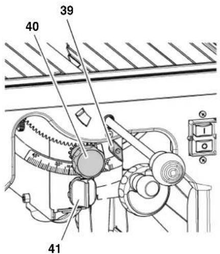
Tilt limiter
The saw blade tilt is limited to 0 and 45° .
For special litre cuts (undercut) the blade tilt can be increased by 1.5° in both directions.
- Loosen locking screw (39).
- Turn sawhead away from the 0° or 45° stop with the knob (40).
- Turn tilt limiter (41) clockwise against the stop.
- The saw blade tilt can now be set over a range from -1.5 - 46.5° .
Universal fence
The universal fence's carriage is set on the saw table's guide extrusion and locked with the knob (45).
In crosscut mode the universal fence can be used for metre cuts:
- Loosen wing nut (42) and set the cutting angle.
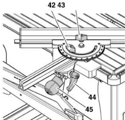
In table saw mode the universal fence is used as rip fence:
- Loosen lock lever (44) and set to required cutting width.
The fence extrusion can be removed after loosening the eccentric clamp (43), and its position shifted:
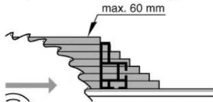
- Wide edge = for cutting thick workpieces (max. 60 mm).
Note: In crop
In crosscut mode the fence extrusion must be installed with the wide edge.
- Small edge =
for cutting thin workpieces;
for bevel cuts (in table saw mode)
6. Initial Operation
6.1 Machine Installation
- Lift machine out of its packaging with two persons.
- Stand machine with the feet on the floor.
- Release locking clips.
- Lift machine at the front and fold down the front legs.
- Swing front lock screws (46) into stop position. If necessary, loosen lock screws.
-
Tighten the front lock screws hand-tight, to securely clamp the legs in their stop position.
-
Lift machine at the rear and fold down the rear legs.
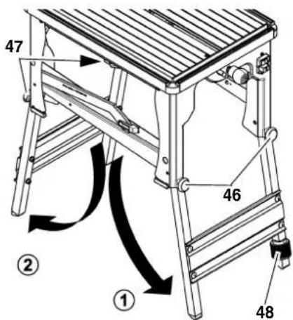
- Swing rear lock screws (47) into stop position. Loosen if necessary.
- Tighten the rear lock screws hand-tight, to securely clamp the legs in their stop position.
- Compensate for any unevenness in the floor with the adjustable foot (48).
Assembly

Danger!
Riving knife and blade guard are part of the safety devices and must be correctly installed for a safe operation.
Adjusting the riving knife

Note:
The riving knife has been correctly set at the factory. Readjustment prior to initial operation is only required should the riving knife have become misadjusted in transit.
- Raise saw blade fully.
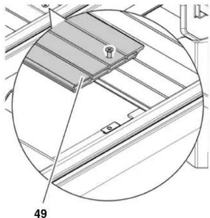
- To check the riving knife alignment: distancebetween the saw blade's outer edge and the riving knife must be 3 - 5mm
Only when realignment of the riving knife is necessary:
3. Loosen removable table section (49) and remove from table.
- Loosen screws (50) holding the riv- ing knife bracket.
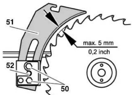
To set the distance to the saw blade:
-
Move riving knife (51) into upper or lower position:
-
Upper position: for parting cuts the riving knife must project over the saw blade.
Lower position: for grooving and set-in work. -
Tighten screws (50) of the riving knife bracket.
- Loosen Allen head screw (52) (to do so, turn Allen head screw clockwise!) and align riving knife: the distance between the outer edge of the saw blade and riving knife must be 3 - 5 mm.
- Tighten Allen head screw (52) (to do so, turn Allen head screw counterclockwise!).
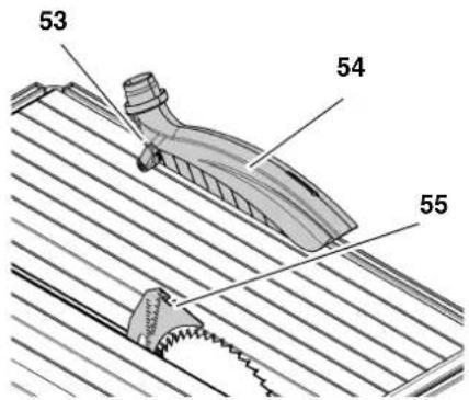
Blade guard installation
- Raise saw blade fully.
- Push blade guard (54) on the riving knife (55).
- Secure blade guard in place by tightening the lock lever (53).
6.2 Dust Collector
Danger!
Some types of wood dust (e.g. beech, oak, ash) may cause cancer when inhaled. Use suitable dust collector when working in enclosed spaces. The dust collector must meet the following requirements:
- hoses to fit outer diameter of dust extraction ports (blade guard 38mm ; chip case 58/43mm );
air flow volume ≥ 460m3 /h
vacuum at dust extraction port of saw ≥ 530Pa
air speed at dust extraction port of saw ≥ 20m / s
The dust extraction ports are located at the chip case assembly and at the saw blade guard.
Follow the Operating Instructions supplied with the dust collector as well!
Operation without a dust collector is only possible:
outdoors;
for short-term operation (up to a maximum of 30 minutes);
- when wearing a dust respirator.

Danger!
By the revolving motion of the saw blade saw dust is blown from the chip case.

Caution!
The dust extraction port must not be blocked by objects.
6.3 Mains Connection

Danger! High voltage
- Operate this machine only in a dry environment.
- Operate machine only on a power source meeting the following requirements (see also "Technical Specifications"):
outlets properly installed, earthed, and tested;
- mainsvoltage and system frequency conform to the voltage and frequency shown on the machine's name plate;
- fuse protection by a residual current operated device (RCD) of 30mA sensitivity;
- system impedance Zmax at the interconnection point (house service connection) 0.35 Ohm maximum;

Note:
Check with your local Electricity Board or electrician if in doubt whether your house service connection meets these requirements.
Make sure that the power supply cable is out of the way, so that it does not interfere with the work and can not be damaged.
- Protect the power supply cable from heat, aggressive liquids and sharp edges.
- Use only rubber-jacketed extension cables of sufficient lead
cross-section (see "Technical Specifications").
- Do not pull on the power supply cable to unplug.
7. Operation

Danger!
This machine shall only be operated by one person at a time. Other persons must stay at a distance to the machine, and only for the purpose of feeding or removing stock.
Before starting work, check to see that the following are in proper working order:
- power cable and plug;
ON/OFF switch; - rving knife;
- blade guard;
push stick.
Use personal protection gear:
- dust respirator;
hearing protection; - safety goggles.
Assume proper operating position:
- at thefront of the saw;
- infront of the machine;
tothe left of the line of cut;
when working with two persons, the other person must remain at an adequate distance to the saw.
If the type of work requires, use the following:
table extension (optional accessory) - if otherwise workpieces would fall off the table after cutting;
- sliding carriage (optional accessory);
- wok clamp - for workpieces that do not rest securely on the saw table - such as round stock;
- dust collector.
-
Avoid typical operator mistakes:
-
Donot try to slow down the saw blade, or stop it, by pushing the workpiece against it from the side. Risk of kickback.
Always hold the workpiece down on the table and do not jam it. Risk of kickback. -
Never cut more than one workpiece at a time - and also no bundles containing several individual pieces. Risk of personal injury if individual pieces are caught by the saw blade uncontrolled.
-
When working in crosscut saw mode check prior to each cut, with the saw blade at standstill, if the blade will clear the fence extrusion when cutting fully through the stock.

Drawing-in/trapping hazard!
- Never cut workpieces to which ropes, cords, strings, cables or wires are attached, or workpieces which contain any of the above.
7.1 Circular Saw
1
Note:
When used as circular saw the workpiece is pushed into the sawblade, to the rear of the saw.
This operating mode is particularly suitable for:
- trimming,
long cuts.
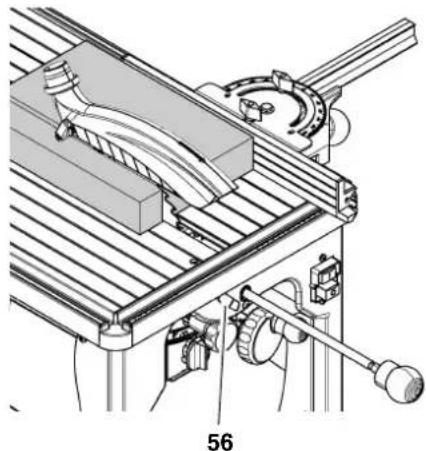
Changing to circular saw mode
- Turn knob of the pull bar counterclockwise and pull forward, towards you, until the saw blade is at the table's centre.
- Arrest the saw blade at the table's centre with the lock lever (56).
Setting and cutting
- Set depth of cut. The blade guard must rest on the workpiece.
- Set blade tilt and lock in position.
- If necessary, install the universal fence (fence parallel with the saw blade).
- Start saw.
- Cut workpiece in a single pass.
- Turn machine off if no further cutting is to be done immediately afterwards.
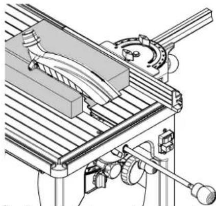
7.2 Crosscut Saw
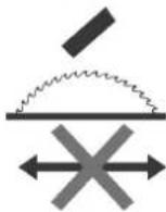
Note: When operated as crosscut saw, the workpiece is fixed to the table and the saw blade pulled forward. Depending on the workpiece thickness the length of cut is limited (see illustration).
This operating mode is particularly suitable for:
crosscuts;
- cutting profiles and non-ferrous metals;
- precision cuts.
- Make sure the pull-action lock lever is disengaged.
- Set depth of cut. The blade guard must rest on the workpiece.
- Set blade tilt and lock in position.
- Install universal fence, set mitre angle if necessary.
i
Note:
In crosscut mode the fence extrusion must be installed with the wide edge.

Caution!
The fence extrusion must not extend into the cutting area.
- With the blade at standstill, check if the workpiece can be cut across its entire width. To do so, turn the pull bar's knob counter-clockwise and pull the saw blade towards you.
- Return saw blade to its rear stop position.
- Place workpiece against the fence extrusion.
- Start saw.
- Turn the pull bar's knob counterclockwise. Cut workpiece by pulling
the saw blade forward, towards you. Return saw blade to its rear stop position.
- Turn machine off if no further cutting is to be done immediately afterwards.
8. Care and Maintenance

Danger!
Prior to all servicing:
- Turn machine OFF.
- Wait until the saw has come to a complete stop.
- Unplug power cable.
After each service, enable all safety devices and check to see that they are fully operational.
- Replace defective parts, especially of safety devices, only with genuine replacement parts. Parts not tested and approved by the manufacturer may cause unforeseeable damage.
Repair and maintenance work other than described in this section should only be carried out by qualified specialists.

Danger!
With a damaged table insert there is a risk of small parts getting stuck between table insert and saw blade, blocking the saw blade. Replace damaged table inserts immediately!
8.1 Saw Blade Change

Danger!
- Directly after cutting, the saw blade can be very hot - burning hazard! Let a hot saw blade cool down. Do not clean a hot saw blade with combustible liquids.
- Risk of injury, even with the saw blade at standstill. Wear gloves when changing blades.
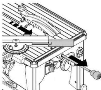
1.Pull knob all the way forward, towards you. - Arrest the saw blade in the forward position with the lock lever.
- Raise saw blade fully.
- Tilt saw blade slightly.
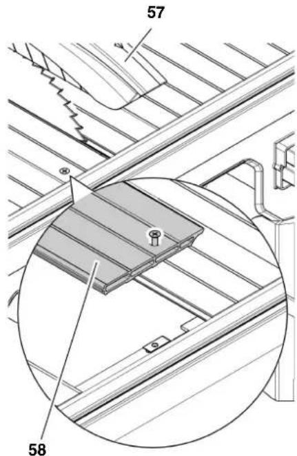
- Remove blade guard (57).
- Loosen removable table section (58) and remove from table.
- Loosen arbor bolt (59) with Allen wrench (left-handed thread!). Use the face spanner as counter-holder.
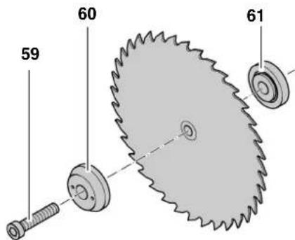
- Remove arbor bolt (59), outer blade flange (60), and saw blade from the saw spindle.
- Clean clamping surfaces of:
-saw spindle,
- saw blade,
- outer blade flange (60),
- inner blade flange (61),
- arbor bolt (59).
Danger!
Do not use cleaning agents (e.g. to remove resin residue) that could corrode the light metal components of the saw; the stability of the saw would be adversely affected.
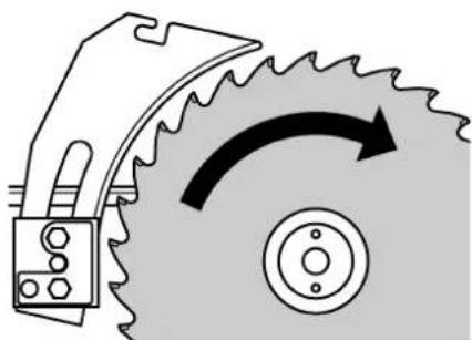
- Put on a fresh saw blade (observe direction of rotation!).

Danger!
Use only saw blades meeting the requirements of EN 847-1 (see "Technical Specifications") - if unsuitable or damaged saw blades parts are used, parts can be ejected due to centrifugal force in an explosive-type manner.
Do not use:
- saw blades which permissible maximum speed is below the rated no-load speed of the saw spindle (see "Technical Specifications");
- saw blades made of high speed steel (HSS);
- Saw blades with visible damage or deformations;
cut-off wheel blades.

Danger!
- Mount saw blade using only genuine parts.
- Do not use loose-fitting reducing rings; the saw blade could work loose.
- Saw blades have to be mounted in such way that they do not wobble or run out of balance and cannot work loose during operation.
- Slide outer blade flange (60) on (overserve centring on flange).
- Turn in arbor bolt (59) (left-handed thread!), and tighten hand-tight only with the tool supplied. Counterhold with an open jaw wrench at the outer blade flange (60).

Danger!
- Do not extend arbor bolt tightening wrench to get more leverage.
- Do not tighten arbor bolt by hitting on the wrench with a hammer or similar.
After tightening the arbor bolt, do not forget to remove the assembly wrench. - Fasten removable table section.
- Attach blade guard.
8.2 Adjusting the Scale
- Loosen all scale fixing screws.
- Place universal fence against the the right-hand side of the saw blade, across its entire diameter (note set of teeth or protruding tips!).
- Lock universal fence in place with the knob.
- Move scale, until the zero mark coincides exactly with the indicated value.
- Tighten all of the scale's fixing screws, re-check the setting.
8.3 Adjusting the Tilt Limiter
- Tilt saw blade against the limit stop.
- Check blade bevel angle:
square (90°) against the saw table
-
45° with a litre square. If these values are not exactly matched:
-
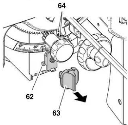
Remove cap (63) with the help of a screwdriver.
- Adjust angle of inclination with screw (62) and the opposite screw.
- Push the cap (63) back on.
- After adjusting the limit stop, check pointer of the angle scale. Re-adjust, if necessary.
- To do so, slightly loosen both screws (64). Align pointer exactly with the zero position.
- Tighten both screws (64) again. Re-check the pointer's position.
8.4 Setting the Motorhead Carriage Damper
The compensation of the blade return action has to be set, so that the motorhead carriage returns completely on its own, without hitting the end position and coming to a sudden stop.
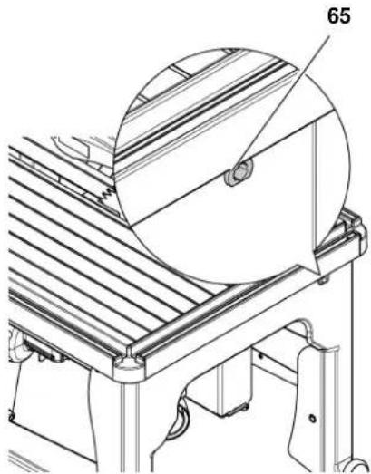
Turn the adjusting screw (65):
- clockwise = more damping
- counter-clockwise = less damping
8.5 Cleaning the Saw
- Remove chips and saw dust with vacuum cleaner or brush:
from saw blade setting guide elements;
from motor vent slots.
Cleaning the chipcase.
If there is sawdust build-up in the chipcase, the chipcase needs cleaning:
i Note: The
The chipcase is only accessible from the underside of the machine. For cleaning, both table insert and saw blade can be removed.
- Loosen Allen screw (66) only slightly.
- Slide cover plate (67) up and unhook from the upper bracket.
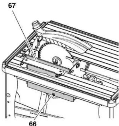
- Clean chipcase.
- Replace cover plate (67).
- Afterwards, tighten Allen screw (66) hand-tight.
8.6 Storage
Danger!
- Store the machine in a way that it cannot be used or tampered with by unauthorised persons.
Make sure that nobody can get hurt by the stored machine.
Caution!
- Never store the machine outdoors, in unprotected areas, or in damp or wet locations.
8.7 Maintenance
Before switching ON
Perform a visual check to see if the distance saw blade -riving knife is 3...5 mm.
Perform a visual check of power cable and power cable plug for damage; if necessary, have damaged parts replaced by a qualified electrician.
Monthly (if used daily)
Remove saw dust and chips with vacuum or brush; apply light coat of oil to guide elements:
threaded rod and guide rods of blade rise and fall mechanism:
- connecting rods;
swivel segments;
damper.
Every 300 hours of operation
Check all nuts, bolts, and screws for proper fit and tightness, re-tighten where necessary.
9. Transport
Danger!
Before each transport:
- Turn machine OFF.
- Wait until the saw has come to a complete stop.
Unplug power cable.
Ensure that the upper part of the saw blade is covered during transport.
Never use the safety installations for handling or transport.
- Lower saw blade fully.
- Lock the saw in the rear stop position with the pull-action lock lever.
- Remove the universal fence.
- Remove blade guard.
- Wind up power supply cable on the cable take-up unit.
- Loosen the rear lock screws (68).
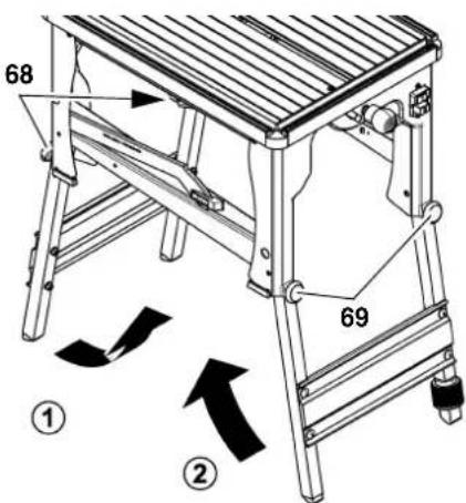
- Lift machine at the rear and fold up the rear legs.
- Loosen the front lock screws (69).
- Lift machine at the front and fold up the front legs.
- Secure the folded-up legs with the locking clip.
- Hold and transport saw at the crossstruts on the sides of the saw table.
If possible, use the original cardboard box for shipping.
10. Tips and Tricks
Before cutting a workpiece to size make trial cuts on pieces of scrap.
Always place a workpiece on the saw table in such way that it cannot tilt or rock (e.g. always place a curved board on the table with the convex side up).
- When working long stock use suitable supports, such as table rear or side extensions (optional accessories).
To simplify repetitive cut-off work, use a stock stop (optional accessory).
- Keep the surfaces of saw table and supports clean – in particular, remove resin residue with a suitable Cleaning and Maintenance Spray (optional accessory).
11. Available Accessories
For special tasks the following accessories are available at your specialised dealer - see back cover for illustrations:
A Ta ble Rear Extension For safe working with long workpieces.
BT able Side Extension For safe working with long workpieces.
C Sliding Carriage For convenient guiding of long stock.
D Wh eel Set
For easy moving.
E Dust Colle c tion Attachment Helps to protect your health, and to keep the shop clean.
F Rip Fence
For long precision cuts.
G Rol Ier Support
For safe working with long workpieces.
H Care and Maintenance Spray To remove resin residue and preserve metal surfaces.
ITC T Saw Blade
220x2.4/1.6x30 36 ATB
For rip and cross cuts in solid wood and particle board.
JTC T Saw Blade
220x2.6/1.6x30 48 inverted V/hollow teeth
For rip and cross cuts in panels; plastics, aluminium and copper profiled extrusions, high-grade veneered sheets.
KTC T Saw Blade
220x2.6/1.6x30 80 square teeth/ trapezoidal
General purpose blade for plastics and NF-metals.
L Push Block Handle
Attaches to a suitable board. For the safe guiding of small workpieces.
12. Repairs
Danger!
Have your power tool serviced by a qualified repair person using only identical replacement parts. This will ensure that the safety of the power tool is maintained.
Contact your local Metabo representative if you have Metabo power tools requiring repairs. See www.metabo.com for addresses.
You can download a list of spare parts from www.metabo.com.
13. Environmental Protection
The machine's packing can be 100% recycled.
Worn out power tools and accessories contain considerable amounts of valuable raw and rubber materials, which are recyclable.
These instructions are printed on paper produced with elemental chlorine-free bleaching process.
14. Trouble Shooting

Danger!
Before carrying out any fault service or maintenance work, always:
- Turn machine OFF.
- Unplug power cable.
- Wait until the saw blade has come to a complete stop.
After each service, enable all safety devices and check to see that they are fully operational.
Motor does not run
Undervoltage relay tripped by power failure:
- switch on again.
No mains voltage:
- check cables, plug, outlet and mains fuse.
Loss of performance
Motor supply voltage too low:
- use a shorter extension cable or extension cable with a larger lead cross section (≥ 1.5mm2) .
have power supply checked by a qualified electrician.
Loss of cutting performance
Saw blade blunt (possibly heat marks on blade body):
- Replace saw blade (see chapter "Maintenance").
Chip ejection tube blocked
No dust collector connected or insufficient suction capacity:
connect to dust collector, or
increase suction capacity (air speed ≥ 20m / sec at chip ejection tube).
Radial pull action not working properly
Compensation of motorhead carriage incorrectly set:
adjust compensation (see section "Maintenance").
Motorhead carriage slowed down by saw dust:
cleanmotorhead carriage guide elements.
- Technical Specifications
| Voltage V 230 (1~50 Hz) | |||
| Wattage power input P1power output \(P_2\) | kWkW | 1.81.3 | |
| Current draw A 8.8 | |||
| Fuse protection min. A 10 | |||
| Protection class IP20 | |||
| Extension cable lead cross section (H07RN-F) mm | 2 | 3 x 1.5 | |
| Rated no-load speed (at 230V) min | -1 | 5000 | |
| Max. cutting speed (at 230V) \(V_{\text{max}}\) | m/s 57 | ||
| Riving knife thickness mm 1,8 | |||
| Saw blade saw blade diameter (outer)saw blade hole (inside)cutting widthmax. base body thickness of the saw blade | mmmmmm | 210 - 220302.4 - 2.61.7 | |
| Depth of cut with saw blade verticalat 45° saw blade tilt | mmmm | 6042 | |
| Max. length of radial pull | mm 295 | ||
| Dimensions | length saw tablewidth saw tableheight (work stand folded up)height (work stand unfolded) | mmmmmm | 674478420878 |
| Machine weight | kg | 25 | |
| Noise emission values (EN 61029-1*), idle running,A-sound pressure level \(L_{pA}\)A-sound power level \(L_{WA}\)Uncertainty K | dB (A)dB (A)dB (A) | 85964 | |
| Noise emission values (EN 61029-1*) under load.A-sound pressure level \(L_{pA}\)A-sound power level \(L_{WA}\)Uncertainty K | dB (A)dB (A)dB (A) | 871014 | |
| Dust collector | diam. suction connector blade guarddiam. suction connector chipcaseair flow volumevacuum at suction connectorair speed at suction connector | mmmm\(m^3/h\)Pa m/s | 3858/4346053020 |
| * The values stated are emission values and as such do not necessarily constitute values which are safe for the workplace. Although there is a correlation between emission levels and environmental impact levels, whether further precautions are neces-sary cannot be derived from this. Factors influencing the actually present environmental impact level in the workplace include the characteristics of the work area and other noise sources, i.e. the number of machines and other neighbouring work processes. Also, permissible workplace values may vary from country to country. This information is intended to assist the user in his estimate of hazards and risks. | |||


- PARTS AND COMPONENTS (STANDARD DELIVERY)
- OPERATING ELEMENTS
- TOOLS
- MACHINE DOCUMENTS
- TABLE OF CONTENTS
- PLEASE READ FIRST
- SAFETY
- 3.1 SPECIFIED CONDITIONS OF USE
- 3.2 GENERAL SAFETY INSTRUCTIONS
- GENERAL HAZARDS
- DANGER! RISK OF ELECTRIC SHOCK
- RISK OF PERSONAL INJURY AND CRUSHING BY MOVING PARTS
- CUTTING HAZARD, EVEN WITH THE CUTTING TOOL AT STANDSTILL
- RISK OF KICKBACK (WORKPIECE IS CAUGHT BY THE SAW BLADE AND THROWN AGAINST THE OPERATOR)
- DRAWING-IN/TRAPPING HAZARD
- HAZARD GENERATED BY INSUFFICIENT PERSONAL PROTECTION GEAR
- RISK OF INJURY BY INHALED WOOD DUST
- HAZARD GENERATED BY MODIFICATION OF THE MACHINE OR USE OF PARTS NOT TESTED AND APPROVED BY THE MANUFACTURER
- HAZARD GENERATED BY TOOL DEFECTS
- RISK OF INJURY BY NOISE
- DANGER FROM BLOCKING WORKPIECES OR WORKPIECE PARTS
- 3.3 SYMBOLS ON THE MACHINE
- 3.4 SAFETY DEVICES
- BLADE GUARD
- RIVING KNIFE
- CONTACT PROTECTION
- PUSH STICK
- SPECIAL PRODUCT FEATURES
- ON/OFF SWITCH
- NOTE
- PULL BAR FOR CROSSCUT MODE
- PULL ACTION LOCK LEVER
- HANDWHEEL FOR SETTING THE DEPTH OF CUT
- TWIST KNOB FOR BLADE TILT
- LOCK SCREW
- TILT LIMITER
- UNIVERSAL FENCE
- NOTE: IN CROP
- INITIAL OPERATION
- 6.1 MACHINE INSTALLATION
- ASSEMBLY
- DANGER
- ADJUSTING THE RIVING KNIFE
- BLADE GUARD INSTALLATION
- 6.2 DUST COLLECTOR
- CAUTION
- 6.3 MAINS CONNECTION
- DANGER! HIGH VOLTAGE
- OPERATION
- 7.1 CIRCULAR SAW
- 1
- CHANGING TO CIRCULAR SAW MODE
- SETTING AND CUTTING
- 7.2 CROSSCUT SAW
- I
- CARE AND MAINTENANCE
- 8.1 SAW BLADE CHANGE
- 8.2 ADJUSTING THE SCALE
- 8.3 ADJUSTING THE TILT LIMITER
- 8.4 SETTING THE MOTORHEAD CARRIAGE DAMPER
- 8.5 CLEANING THE SAW
- CLEANING THE CHIPCASE
- I NOTE: THE
- 8.6 STORAGE
- 8.7 MAINTENANCE
- BEFORE SWITCHING ON
- MONTHLY (IF USED DAILY)
- EVERY 300 HOURS OF OPERATION
- TRANSPORT
- BEFORE EACH TRANSPORT
- ENSURE THAT THE UPPER PART OF THE SAW BLADE IS COVERED DURING TRANSPORT
- TIPS AND TRICKS
- AVAILABLE ACCESSORIES
- REPAIRS
- ENVIRONMENTAL PROTECTION
- TROUBLE SHOOTING
- MOTOR DOES NOT RUN
- LOSS OF PERFORMANCE
- LOSS OF CUTTING PERFORMANCE
- CHIP EJECTION TUBE BLOCKED
- RADIAL PULL ACTION NOT WORKING PROPERLY
Brand : METABO
Model : UK 290
Category : Saw