DFT060FMZ - Screwdriver MAKITA - Free user manual and instructions
Find the device manual for free DFT060FMZ MAKITA in PDF.
Download the instructions for your Screwdriver in PDF format for free! Find your manual DFT060FMZ - MAKITA and take your electronic device back in hand. On this page are published all the documents necessary for the use of your device. DFT060FMZ by MAKITA.
USER MANUAL DFT060FMZ MAKITA
Cordless Screwdriver INSTRUCTION MANUAL 4
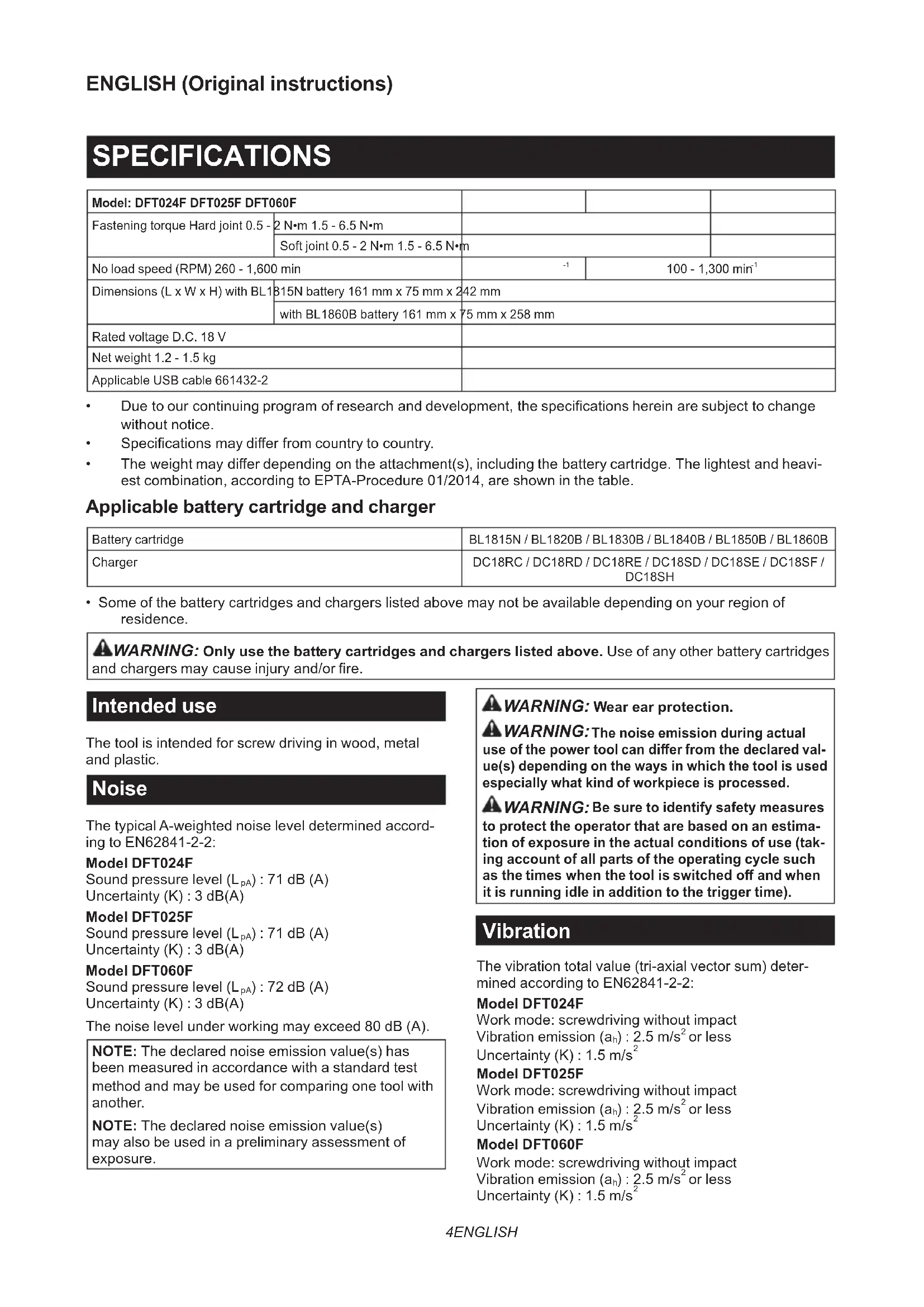
- Specicationsmaydierfromcountrytocountry.
- Theweightmaydierdependingontheattachment(s),includingthebatterycartridge.Thelightestandheavi- est combination, according to EPTA-Procedure 01/2014, are shown in the table. Applicable battery cartridge and charger Battery cartridge BL1815N / BL1820B / BL1830B / BL1840B / BL1850B / BL1860BCharger DC18RC / DC18RD / DC18RE / DC18SD / DC18SE / DC18SF / DC18SH
- Some of the battery cartridges and chargers listed above may not be available depending on your region of residence.
WARNING: Only use the battery cartridges and chargers listed above. Use of any other battery cartridges
andchargersmaycauseinjuryand/orre. Intended use The tool is intended for screw driving in wood, metal and plastic. Noise The typical A-weighted noise level determined accord- ing to EN62841-2-2: Model DFT024F Sound pressure level (L
) : 72 dB (A) Uncertainty (K) : 3 dB(A) The noise level under working may exceed 80 dB (A). NOTE: The declared noise emission value(s) has been measured in accordance with a standard test method and may be used for comparing one tool with another. NOTE: The declared noise emission value(s) may also be used in a preliminary assessment of exposure.
WARNING: Wear ear protection.
The noise emission during actual use of the power tool can dier from the declared val- ue(s) depending on the ways in which the tool is used especially what kind of workpiece is processed.
Be sure to identify safety measures to protect the operator that are based on an estima- tion of exposure in the actual conditions of use (tak- ing account of all parts of the operating cycle such as the times when the tool is switched o and when it is running idle in addition to the trigger time). Vibration The vibration total value (tri-axial vector sum) deter- mined according to EN62841-2-2: Model DFT024F Work mode: screwdriving without impact Vibration emission (a
Model DFT025F Work mode: screwdriving without impact Vibration emission (a
Model DFT060F Work mode: screwdriving without impact Vibration emission (a
or less Uncertainty (K) : 1.5 m/s 25 ENGLISH NOTE: The declared vibration total value(s) has been measured in accordance with a standard test method and may be used for comparing one tool with another. NOTE: The declared vibration total value(s) may also be used in a preliminary assessment of exposure.
WARNING: The vibration emission during
actual use of the power tool can dier from the declared value(s) depending on the ways in which the tool is used especially what kind of workpiece is processed.
WARNING: Be sure to identify safety mea-
sures to protect the operator that are based on an estimation of exposure in the actual conditions of use (taking account of all parts of the operating cycle such as the times when the tool is switched o and when it is running idle in addition to the trigger time). Declarations of Conformity For European countries only The Declarations of conformity are included in Annex A to this instruction manual. SAFETY WARNINGS General power tool safety warnings
WARNING: Read all safety warnings, instruc-
tions, illustrations and specications provided with this power tool. Failure to follow all instructions listedbelowmayresultinelectricshock,reand/or serious injury. Save all warnings and instruc- tions for future reference. The term "power tool" in the warnings refers to your mains-operated (corded) power tool or battery-operated (cordless) power tool. Cordless screwdriver safety warnings
1. Hold the power tool by insulated gripping
surfaces, when performing an operation where the fastener may contact hidden wiring. Fasteners contacting a "live" wire may make exposed metal parts of the power tool "live" and could give the operator an electric shock.
2. Always be sure you have a rm footing.
Be sure no one is below when using the tool in high locations.
3. Hold the tool rmly.
4. Keep hands away from rotating parts.
5. Do not touch the bit or the workpiece immedi-
ately after operation; they may be extremely hot and could burn your skin.
6. Always secure workpiece in a vise or similar
7. Make sure there are no electrical cables, water
pipes, gas pipes etc. that could cause a hazard if damaged by use of the tool. SAVE THESE INSTRUCTIONS.
WARNING: DO NOT let comfort or familiarity
with product (gained from repeated use) replace strict adherence to safety rules for the subject product. MISUSE or failure to follow the safety rules stated in this instruction manual may cause serious personal injury. Important safety instructions for battery cartridge
1. Before using battery cartridge, read all instruc-
tions and cautionary markings on (1) battery charger, (2) battery, and (3) product using battery.
2. Do not disassemble or tamper with the battery
cartridge.Itmayresultinare,excessiveheat, or explosion.
3. If operating time has become excessively
shorter, stop operating immediately. It may result in a risk of overheating, possible burns and even an explosion.
If electrolyte gets into your eyes, rinse them out with clear water and seek medical attention right away. It may result in loss of your eyesight.
5. Do not short the battery cartridge:
(1) Do not touch the terminals with any con- ductive material. (2) Avoid storing battery cartridge in a con- tainer with other metal objects such as nails, coins, etc. (3) Do not expose battery cartridge to water or rain. A battery short can cause a large current ow, overheating, possible burns and even a breakdown.
6. Do not store and use the tool and battery car-
tridge in locations where the temperature may reach or exceed 50 °C (122 °F).
7. Do not incinerate the battery cartridge even if
it is severely damaged or is completely worn out. The battery cartridge can explode in a re.
8. Do not nail, cut, crush, throw, drop the battery
cartridge, or hit against a hard object to the battery cartridge. Such conduct may result in a re,excessiveheat,orexplosion.
9. Do not use a damaged battery.
The contained lithium-ion batteries are subject to the Dangerous Goods Legislation requirements. For commercial transports e.g. by third parties, forwarding agents, special requirement on pack- aging and labeling must be observed. For preparation of the item being shipped, consulting an expert for hazardous material is required. Please also observe possibly more detailed national regulations. Tapeormaskoopencontactsandpackupthe battery in such a manner that it cannot move around in the packaging.6 ENGLISH
11. When disposing the battery cartridge, remove
it from the tool and dispose of it in a safe place. Follow your local regulations relating to disposal of battery.
12. Use the batteries only with the products
specied by Makita. Installing the batteries to non-compliantproductsmayresultinare,exces- sive heat, explosion, or leak of electrolyte.
13. If the tool is not used for a long period of time,
the battery must be removed from the tool.
14. During and after use, the battery cartridge may
take on heat which can cause burns or low temperature burns. Pay attention to the han- dling of hot battery cartridges.
15. Do not touch the terminal of the tool imme-
diately after use as it may get hot enough to cause burns.
16. Do not allow chips, dust, or soil stuck into the
terminals, holes, and grooves of the battery cartridge. It may result in poor performance or breakdown of the tool or battery cartridge.
17. Unless the tool supports the use near
high-voltage electrical power lines, do not use the battery cartridge near high-voltage electri- cal power lines. It may result in a malfunction or breakdown of the tool or battery cartridge.
18. Keep the battery away from children.
SAVE THESE INSTRUCTIONS. CAUTION: Only use genuine Makita batteries. Use of non-genuine Makita batteries, or batteries that have been altered, may result in the battery bursting causingres,personalinjuryanddamage.Itwill also void the Makita warranty for the Makita tool and charger. Tips for maintaining maximum battery life
1. Charge the battery cartridge before completely
discharged. Always stop tool operation and charge the battery cartridge when you notice less tool power.
2. Never recharge a fully charged battery car-
tridge. Overcharging shortens the battery service life.
3. Charge the battery cartridge with room tem-
perature at 10 °C - 40 °C (50 °F - 104 °F). Let a hot battery cartridge cool down before charging it.
4. When not using the battery cartridge, remove
it from the tool or the charger.
5. Charge the battery cartridge if you do not use
it for a long period (more than six months). FUNCTIONAL DESCRIPTION CAUTION: Always be sure that the tool is switched o and the battery cartridge is removed before adjusting or checking function on the tool. Installing or removing battery cartridge CAUTION: Always switch o the tool before installing or removing of the battery cartridge. CAUTION: Hold the tool and the battery car- tridge rmly when installing or removing battery cartridge. Failure to hold the tool and the battery cartridgermlymaycausethemtoslipoyourhands and result in damage to the tool and battery cartridge and a personal injury. ►Fig.1: 1. Red indicator 2. Button 3. Battery cartridge To remove the battery cartridge, slide it from the tool while sliding the button on the front of the cartridge. To install the battery cartridge, align the tongue on the battery cartridge with the groove in the housing and slip it into place. Insert it all the way until it locks in place with a little click. If you can see the red indicator as showninthegure,itisnotlockedcompletely. CAUTION: Always install the battery cartridge fully until the red indicator cannot be seen. If not, it may accidentally fall out of the tool, causing injury to you or someone around you. CAUTION: Do not install the battery cartridge forcibly. If the cartridge does not slide in easily, it is not being inserted correctly. Indicating the remaining battery capacity Only for battery cartridges with the indicator ►Fig.2: 1. Indicator lamps 2. Check button Press the check button on the battery cartridge to indi- cate the remaining battery capacity. The indicator lamps light up for a few seconds. Indicator lamps Remaining capacityLighted O Blinking75% to 100%50% to 75%25% to 50%0% to 25%Charge the battery.The battery may havemalfunctioned.7 ENGLISH NOTE: Depending on the conditions of use and the ambienttemperature,theindicationmaydierslightly from the actual capacity. NOTE:Therst(farleft)indicatorlampwillblinkwhen the battery protection system works. Tool / battery protection system The tool is equipped with a tool/battery protection sys- tem.Thissystemautomaticallycutsopowertothe motor to extend tool and battery life. The tool will auto- matically stop during operation if the tool or battery is placed under one of the following conditions: Overload protection When the tool/battery is operated in a manner that causes it to draw an abnormally high current, the tool stopsautomatically.Inthissituation,turnthetoolo and stop the application that caused the tool to become overloaded. Then turn the tool on to restart. Overheat protection When the tool/battery is overheated, the tool stops automatically. In this situation, let the tool/battery cool before turning the tool on again. Overdischarge protection When the battery capacity is not enough, the tool stops automatically. In this case, remove the battery from the tool and charge the battery. Switch action
WARNING: Before installing the battery car-
tridge into the tool, always check to see that the switch trigger actuates properly and returns to the "OFF" position when released. To start the tool, simply pull the switch trigger. Release the switch trigger to stop. ►Fig.3: 1. Switch trigger NOTE: For approximately one second after fastening, the tool does not work even with the switch pulled. Lighting up the front lamp ►Fig.4: 1. Lamp CAUTION: Do not look in the light or see the source of light directly. Pull the switch trigger to light up the lamp. The lamp keeps on lighting while the switch trigger is being pulled. The lamp goes out approximately 10 seconds after releasing the switch trigger. NOTE:Useadryclothtowipethedirtothelensof the lamp. Be careful not to scratch the lens of lamp, or it may lower the illumination. Reversing switch action ►Fig.5: 1. Reversing switch lever CAUTION: Always check the direction of rotation before operation. CAUTION: Use the reversing switch only after the tool comes to a complete stop. Changing the direction of rotation before the tool stops may dam- age the tool. CAUTION: When not operating the tool, always set the reversing switch lever to the neu- tral position. This tool has a reversing switch to change the direction of rotation. Depress the reversing switch lever from the A side for clockwise rotation or from the B side for coun- terclockwise rotation. When the reversing switch lever is in the neutral posi- tion, the switch trigger cannot be pulled.8 ENGLISH LED indicator / Beeper ►Fig.6: 1. LED indicator LED indicator / Beeper on the tool shows the following functions. Function Status of the tool Status of the LED indicator/beeper Action to be taken LED indicator Beeper Check of the LED indi- cator, light and beeper operation When the battery car- tridge is installed, the tool checks for its LED indica
tor, light and beeper. Lightsuprstingreen, next red. (And then the light comes on.) A series of very short beeps
Detection of switch trigger operation when installing battery When the battery car- tridge is installed with the switch trigger pulled, the tool stops to avoid unintentional start. Blinks in red and green alternatively. A series of short beeps Release the switch trigger. Auto-stop with fastening completion The tool setting has been achieved and the tool has stopped. Lights up in green for approximately one second.
Alarmagainstinsu- cient fastening The tool has not completed the tool setting because the switch trigger has released before reaching the set val- ues. Otherwise, the settings of "Failure Criteria for Phase" has been achieved. Lights up in red. A long beep Retighten the screw. Intermission between the phases The tool is in the inter- mittingperiodcongured by the setting of "Shift to the next Phase". Lights up or blinks in green (depending on settings)
Double-hitting detection When the operator starts to re-fasten an already-fas
tened screw, the tool detect it and stops. Lights up in red. A long beep – Alarm for low battery capacity The battery power became low and it is time to replace the battery cartridge. Blinks in red slowly. A series of long beeps Replace the battery with fully charged one. Auto-stop with low remaining battery capacity The battery power is almost used up and the tool stopped. Lights up in red. A long beep Replace the battery with fully charged one. Anti-reset of controller The battery voltage dropped abnormally for some reason, and the tool stopped. Blinks in red and green alternatively. A series of short beeps Replace the battery with fully charged one. Overheat protection The motor or the control- ler heated up abnormally and the tool stopped. Blinks in red quickly. A series of short beeps Remove the battery car- tridge immediately and cool the tool down. Failure to detect heat of motor The detection unit of the motor fails to detect the heat because the cord has broken or other reasons. Blinks in red quickly. A series of short beeps Remove the battery cartridge and cool the tool down. If the indicator does not stop, ask your local Makita Service Center for repair. Motor failure detection Motor failure has been detected. At this time, tool does not work. Blinks in red and green alternatively. A series of short beeps Ask your local Makita Service Center for repair. Maintenance alarm A maintenance time has come according to your preset number of screws driven. Blinks in yellow. – Reset the alarm with the application software. Alarm for unavailable data communication (with the tool in connec- tion with PC) Data cannot be exchanged between the tool and PC in spite of the connection. Blinks in yellow. – Restart the application software and re-connect the USB cable. Indication that data com- munication is available (with the tool in connec- tion with PC) The tool is connected to PC and data communi- cation is available. Blinks in green. – –9 ENGLISH Adjusting the fastening torque When you wish to drive machine screws, hex bolts, etc. with the predetermined torque, adjust the fastening torque as follows.
1. Open the change plate by hand so that you can
see a hole. ►Fig.7: 1. Change plate
2. Pull the switch trigger and release it so that the
adjust ring rotates and the hole becomes visible. And then remove the battery cartridge.
3. Use an optional adjust grip to adjust the fastening
torque. Insert the pin of the adjust grip into the hole in the front of the tool. And then, turn the adjust grip clockwise to set a greater fastening torque, and coun- terclockwise to set a smaller fastening torque. ►Fig.8: 1. Adjust grip 2. Hole for adjust grip
4. Insert the battery cartridge and be sure that a
fastening torque has been set up by using a fastening torque tester.
5. Close the change plate by hand securely.
Adjusting no-load speed and revolution angle etc. You can adjust the no-load speed, number of turn, etc. of the tool with your computer. Install the application software in your computer and connect it to the tool with an USB cable. ►Fig.9: 1. USB port 2. USB cover 3. USB cable NOTICE: Make sure that the USB cover closed when fastening. NOTE: Use the makita genuine USB cable to con- nect your computer to the tool. Refer to the section "SPECIFICATIONS". NOTE: For the application software, please contact Makita sales representative. ASSEMBLY CAUTION: Always be sure that the tool is switched o and the battery cartridge is removed before carrying out any work on the tool. Installing or removing driver bit/ socket bit ►Fig.10 Use only driver bit/socket bit that has inserting portion showninthegure.Donotuseanyotherdriverbit/ socket bit. For tool with shallow driver bit hole A=12mm B=9mm Use only these type of driver bit. Follow the procedure
1. (Note) Bit-piece is not
necessary. For tool with deep driver bit hole A=17mm B=14mm To install these types of driver bits, follow the procedure 1. A=12mm B=9mm To install these types of driver bits, follow the procedure 2. (Note) Bit-piece is necessary for installing the bit. Procedure 1 For tool without one-touch type sleeve ►Fig.11: 1. Driver bit 2. Sleeve To install the driver bit, pull the sleeve in the direction of the arrow and insert the driver bit into the sleeve as far as it will go. Then release the sleeve to secure the driver bit. For tool with one-touch type sleeve To install the driver bit, insert the driver bit into the sleeve as far as it will go. Procedure 2 In addition to Procedure 1, insert the bit-piece into the sleeve with its pointed end facing in. ►Fig.12: 1. Driver bit 2. Bit-piece 3. Sleeve To remove the driver bit, pull the sleeve in the direction of the arrow and pull the driver bit out. NOTE: If the driver bit is not inserted deep enough into the sleeve, the sleeve will not return to its original position and the driver bit will not be secured. In this case, try re-inserting the bit according to the instruc- tions above. NOTE:Whenitisdiculttoinsertthedriverbit,pull the sleeve and insert it into the sleeve as far as it will go. NOTE: After inserting the driver bit, make sure that it isrmlysecured.Ifitcomesout,donotuseit. Installing hook Optional accessory The hook is useful to hang the tool. Install the hook to the holes on the tool body. ►Fig.13: 1. Hook 2. Hole OPERATION Screwdriving operation CAUTION: Make sure that the bit is inserted straight in the screw head, or the screw and/or bit may be damaged. Place the point of the driver bit in the screw head and apply pressure to the tool. Then switch the tool on. When the clutch cuts in, the motor will stop automati- cally. Then release the switch trigger. ►Fig.1410 ENGLISH Limits of fastening capacity Use the tool within the limits of fastening capacity. If you use the tool beyond the limits, the clutch does not work. And the tool cannot deliver enough fastening torque. For model DFT024F / DFT025F 360° 300° 240° 180° 120° 60° 30°
1. Range of fastening capacity 2. Rotation angle
1. Range of fastening capacity 2. Rotation angle
NOTE: The rotation angle is the angle from the point that the bolt is tightened in 50% of desired torque to the point that the bolt is tightened in 100% torque. NOTE: Use of a cold battery cartridge may give warning for battery capacity by LED indicator and beeper and stop the tool immediately, even if it is fully charged. In this case, the fastening capacity may be inferiortothespecicationonthismanual. MAINTENANCE CAUTION: Always be sure that the tool is switched o and the battery cartridge is removed before attempting to perform inspection or maintenance. NOTICE: Never use gasoline, benzine, thinner, alcohol or the like. Discoloration, deformation or cracks may result. To maintain product SAFETY and RELIABILITY, repairs, any other maintenance or adjustment should be performed by Makita Authorized or Factory Service Centers, always using Makita replacement parts. OPTIONAL ACCESSORIES CAUTION: These accessories or attachments are recommended for use with your Makita tool specied in this manual. The use of any other accessories or attachments might present a risk of injury to persons. Only use accessory or attachment for its stated purpose. If you need any assistance for more details regard- ing these accessories, ask your local Makita Service Center.
- Protector (Natural, Red, Blue, Yellow, Green)
- Lock nut (Red, Blue, Yellow)