
Poly D - Synthesizer BEHRINGER - Free user manual and instructions
Find the device manual for free Poly D BEHRINGER in PDF.
| Product type | Polyphonic analog synthesizer |
| Keyboard | 37 keys (3 octaves), standard size, semi-weighted |
| Polyphony | 4 voices (Poly mode) |
| Oscillators | 4 oscillators (OSC1-4), waveforms: triangle, sawtooth, square, pulse (medium and narrow) |
| Filter | Low-pass/high-pass, resonance (Emphasis), ADSR envelope, keyboard tracking (3 levels) |
| LFO | Triangle and square waveforms, adjustable rate |
| Sequencer | 32 steps, 8 patterns, 8 banks, step and keyboard modes, ratchet, glide, swing |
| Arpeggiator | 8 modes (Up, Down, Up/Down, Random, etc.), hold |
| Built-in effects | Chorus I, Chorus II, Chorus I+II; Distortion (level, tone, gain) |
| Connectors | Main outputs 6.35 mm TRS balanced, headphone output, line input (Ext In), MIDI In/Out/Thru, USB MIDI (type B), CV/Gate inputs (Pitch, Velocity, Aftertouch, Filter, Loudness, Oscillator, V-Trig, Ext Trig), Sync In/Out |
| Power supply | Included 12V DC power adapter, 100-240V AC, 50/60 Hz |
| Dimensions (approx.) | 70 cm x 30 cm x 10 cm |
| Weight (approx.) | 6 kg |
| Included accessories | Power adapter, user manual |
| Power consumption | 15 W (maximum) |
| Operating temperature | 0°C to 45°C |
| Maintenance and cleaning | Clean with a dry cloth. Do not use solvents. |
| Safety | Do not expose to water, rain or moisture. Do not open the enclosure. Use only the supplied adapter. |
| Spare parts and repairability | No user-serviceable parts. Contact qualified technician. |
| General information | Brand: Behringer, Model: Poly D, Category: Synthesizer |
Frequently Asked Questions - Poly D BEHRINGER
User questions about Poly D BEHRINGER
0 question about this device. Answer the ones you know or ask your own.
Ask a new question about this device
Download the instructions for your Synthesizer in PDF format for free! Find your manual Poly D - BEHRINGER and take your electronic device back in hand. On this page are published all the documents necessary for the use of your device. Poly D by BEHRINGER.
USER MANUAL Poly D BEHRINGER
Analog 4-Voice Polyphonic Synthesizer with 37 Full-Size Keys, 4 VCOs, Classic Ladder Filter, LFO, BBD Stereo Chorus, Distortion, 32-Step Sequencer and Arpeggiator
2 POYD Quick Start Guide 3
EN
ES
EN Important Safety Instructions
Terminals marked with this symbol carry electrical current of sufficient magnitude to constitute risk of electric shock. the only high quality professional speaker tables with 15" TS or twist-locking plugs pre installed. All other installation or modification should be performed only by qualified personnel.
This symbol, wherever it appears, alerts you to the presence of uninsulated dangerous voltage inside the enclosure - voltage that may be sufficient to constitute a risk of shock.
This symbol, wherever it appears, alerts you to important operating and maintenance instructions in the accompanying literature. Please read the manual.
Caution To reduce the risk of electric shock, do not remove the top cover (or the rear section). No user serviceable parts include. Refer servicing to qualified personnel.
Caution To reduce the risk of fire or electric shock, do not expose this appliance to rain and moisture. The apparatus shall not be exposed to dripping or splashing liquids and no objects filled with liquids, such as wares, shall be plated on the apparatus.
Caution These service instructions are for use by qualified service personnel only. To reduce the risk of electric shock do not perform any servicing other than that contained in the operation instructions. Repairs have to be performed by qualified service personnel.
- Read these instructions.
- Keep these instructions.
- Here all warnings.
- Follow all instructions.
- Do not use this apparatus near water.
- Clean only with dry cloth.
- Do not hide any ventilation openings, install in accordance with the manufacturer's instructions.
-
Do not install near any heat sources such as rotators, heat registers, stoves, or other apparatus (including amplifiers) that produce heat.
-
Do not defeat the safety purpose of the polarized or grounding-type plug. A polarized plug has two blades with one wider than the other. A grounding-type plug has two blades and a third grounding proing. The wide blade or the third proing are provided for your safety. If the provided plug does not fit into your outlet, consult an electrician for replacement of the obsolete outlet.
-
Protect the power card from being walked on or pinched particularly at plugs, convenience receptacles, and the point where they exit from the apparatus.
- Use only attachments/accessories specified by the manufacturer.

- Use only with the cart, stand, tripod, bracket, or table specified by the manufacturer, or sold with the apparatus. When a cart is used, use caution when moving the cart/apparatus combination to avoid
injury from tip-over.
-
Unplug this apparatus during lightning storms or when unused for long periods of time.
-
Refer all servicing to qualified service personnel. Servicing is required when the apparatus has been damaged in any way, such as power supply cord or plug in damaged, liquid has been spilled or objects have fallen into the apparatus, the apparatus has been exposed to rain or moisture, does not operate normally, or has been dropped.
-
The apparatus shall be connected to a MUNG socket outlet with a protective earthing connection.
-
Where the MAINS plug or an appliance coupler is used as the disconnect device, the disconnect device shall remain nearly operable.

- Correct disposal of this product: This symbol indicates that this product must not be disposed of with household waste, according to the WEE Directive (2012/19/EU) and
should be taken to a collection center formed for the recycling of waste electrical and electronic equipment (EEL). The misunderstanding of this type of waste could have a possible negative impact on the environment and human health due to potentially hazardous substances that are generally associated with EEL, at the same time, your corporation in the correct disposal of this product will contribute to the efficient use of natural resources. For more information about where you can take your waste equipment for recycling, please contact your local city office, or your household waste collection service. 18. Do not install in a confined space, such as a book case or similar unit.
-
Do not place naked flame sources, such as lighted candles, on the apparatus.
-
Please keep the environmental aspects of battery disposal in mind. Batteries must be disposed-of at a battery collection point.
-
This apparatus may be used in tropical and moderate climates up to 45°C.
LEGAL DISCLAIMER
Music Tribe accepts no liability for any loss which may be suffered by any person who relies either wholly or in part upon any description, photograph, or statement contained herein. Technical specifications, appearances and other information are subject to change without notice. All trademarks are the property of their respective owners. Midas, Mark Teink, Lab Suggers, Lake, Tammy, Turbosound, TC Electronic, TC Hollison, Behringer, Suggie, Cherhelim, Amazone and Cuslaudic are trademarks or registered trademarks of Music Tribe Global Brands Ltd. © Music Tribe Global Brands Ltd. 2021. All rights reserved.
LIMITED WARRANTY
For the applicable warranty terms and conditions and additional information regarding Music Tribe's Limited Warranty, please see complete details online at musictribe.com/warranty.
ES
BESCHRÄNKTE GARANTIE
14 PCIYD
Quick Star Guide 15
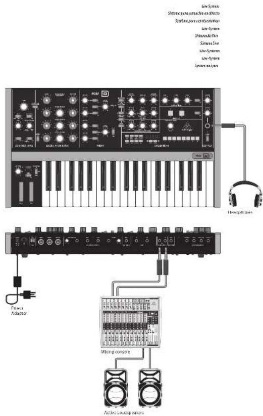
POLY D Hook-up
EN Step 1: Hook-Up
ES Paso 1: Conexión
FR Etape 1 : Connexions
DE Schritt 1: Verkabelung
PT Passo 1: Conexões
IT Passo 1: Allacciare
NL Stap 1: Hook-Up
SE Steg 1: Anslutning
PL Krok 1: Podłączeni
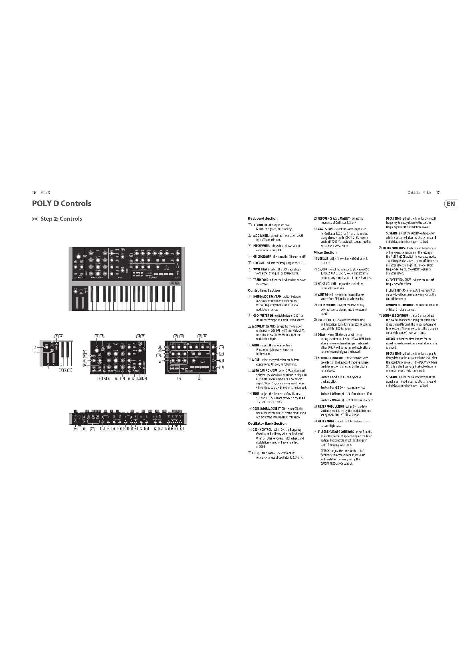
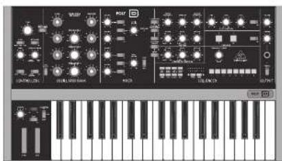
POLY D Controls
EN Step 2: Controls
natural_image
Front view of a black electronic audio workstation with control knobs, dials, and keyboard (no visible text or labels)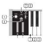
Keyboard Section
① KEYBOARD - the keyboard has 37 semi-weighted, full-size keys.
MOD WHEEL - adjust the modulation depth from off to maximum.
5 PITCH WHEEL - this wheel allows you to lower or raise the pitch.
[4] GLIDE ON/OFF - this turns the Glide on or off.
LFO RATE-adjusts the frequency of the LFO.
5. WAVE SHAPE - select the IFO wave shape from either triangular or square wave.
TRANSPOSE - adjust the keyboard up or down one octave.
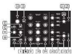
Controllers Section
☐ NOISE (MOD SRC)/ LFO switch between Noise (or external modulation source) or Low Frequency Oscillator (LFO) as a modulation source.
③ OSC4/FILTER EG switch between OSC 4 or the Filter Envelope as a modulation source.
⑪ MODULATION MIX - adjust the modulation mix between OSC4/Tilter EG and HolseyLED. Note: Use the MOD WHEEL to adjust the modulation depth.
☑ GLIDE - adjust the amount of Glide (Portamento), between notes on the keyboard.
⑫ MODE - select the synthesizer mode from Monophonic, Unison, or Polyphonic.
(18) AUTO DAMP ON/OFF- when OFF, and a chord is played, the chord will continue to play until all its notes are released, or a new note is played. When OH, only non-released notes will continue to play; the others are damped.
TUNE - adjust the frequency of oscillators 1, 2, 3, and 4. (OSCA is not affected if the OSC4 CONTROL switch is off.)
[15] OSCILLATOR MODULATION - when ON, the oscillators are modulated by the modulation mix, set by the MODULATION MIX knob.
Oscillator Bank Section
(3) OSC 4 CONTROL - when ON, the frequency of Oscillator 4 will vary with the keyboard. When OFF, the keyboard, Pitch wheel, and Modulation wheel, will have no effect on OSC4.
17 FREQUENCY RANGE - select from six frequency ranges of Oscillator 1, 2, 3, or 4.
[18] FREQUENCY ADJUSTMENT - adjust the frequency of Oscillator 2, 3, or 4.
WAVE SHAPE select the wave shape used for Oscillator 1, 2, 3, or 4 from: triangular, triangular/sawtooth (OSC 1, 2, 3), reverse sawtooth (OSC 4), sawtooth, square, medium pulse, and narrow pulse.
Mixer Section
☒ VOLUME - adjust the volume of Oscillator 1, 2, 3, or 4.
[2] ON/OFF - select the sources to play from OSC 1, OSC 2, OSC 3, OSC 4, Noise, and External Input, or any combination of these 6 sources.
☐ NOISE VOLUME - adjust the level of the internal Noise source.
WHITET/PINK switch the internal Noise source from Pink noise to White noise.
[26] EXT IN VOLUME - adjust the level of any external source playing into the external input.
OVERLOAD LED - to prevent overloading and distortion, turn down the DT IN volume control if this LED turns on.
☑ DECAY when OK, the signal will decay during the time set by the DECAY TIME knob after a note or external trigger is released. When OFF, it will decay immediately after a note or external trigger is released.
[2]: KEYBOARD CONTROL - these switches vary the effect of the keyboard tracking, where the filter section is affected by the pitch of note played.
Switch 1 and 2 OFF - no keyboard tracking effect
Switch 1 and 2 ON - maximum effect
Switch 1 ON (only) - 1/3 of maximum effect
Switch 2 ON (only) - 2/3 of maximum effect
FILTER MODULATION - when ON, the filter section is modulated by the modulation mix, set by the MODULATION MIX knob.
☑ FILTER MODE - select the filter between Low-pass or High-pass.
11 FILTER ENVELOPE CONTROLS - these 3 knobs adjust the overall shape enveloping the filter section. The controls affect the change in cutoff frequency with time.
ATTACK - adjust the time for the cutoff frequency to increase from its set value and reach the frequency set by the CUTOFF FREQUENCY control.
DECAY TIME - adjust the time for the cutoff frequency to decay down to the sustain frequency after the attack time is over.
SUSTAIN - adjust the cutoff to a frequency which is sustained after the attack time and initial decay time have been reached.
FILTER CONTROLS - the filter can be low-pass or high-pass, depending on the setting of the FILTER MODE switch. In low-pass mode, audio frequencies above the cutoff frequency are attenuated. In high-pass mode, audio frequencies below the cutoff frequency are attenuated.
CUTOFF FREQUENCY - adjusts the cut-off frequency of the filter.
FILTER EMPHASIS - adjusts the amount of volume level boost (resonance) given at the cut-off frequency.
AMOUNT OF CONTOUR - adjusts the amount of Filter Envelope contour.
☐ LOUDNESS CONTOUR – these 3 knobs adjust the overall shape enveloping the audio after it has passed through the mixer section and filter section. The controls affect the change in volume (loudness) level with time.
ATTACK - adjust the time it takes for the signal to reach a maximum level after a note is played.
DECAY TIME - adjust the time for a signal to decay down to the sustain volume level after the attack time is over. If the DECAY switch is ON, this is also how long it takes to decay to minimum once a note is released.
SUSTAIN - adjust the volume level that the signal is sustained after the attack time and initial decay time have been reached.
POLY D Controls
EN Step 2: Controls
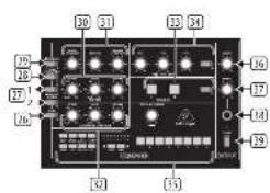
Chorus Section
⑬ CHORUS I - this adds quality and a spatial sense to the audio output. The chorus effects are enhanced when listening in stereo.
CHORUS II - this adds a deeper chorus effect.
CHORUS I and II can both be on for a deeper effect.
ON/OFF - turns Chorus on/off.
Distortion Section
(24) DISTORTION - adjust the amount of distortion.
TONE - adjust the distortion tone. LEVEL - adjust the distortion output level. ON/OFF - turns Distortion on/off.
(25) SEQUENCER - see details on page 15 and 38.
Output Section
⑬ VOLUME – adjust the overall volume level of the synthesizer output.
(1) PHONES - adjust the overall volume level of the PHONES output.
PHONES - connect your headphones to this 3/4 TRS output. Make sure the headphone volume is turned down before putting on headphones.
ED POWER - turn the synthesizer on or off. Make sure all the connections are made before turning on the unit. The LED shows when power is applied and the synthesizer is turned on.
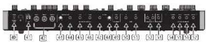
Rear Panel
DC INPUT - connect the supplied 12V DC power adapter here. The power adapter can be plugged into an AC outlet capable of supplying from 100V to 240V at 50 Hz/60 Hz. Use only the power adapter supplied.
(3). USB PORT - This USB type B jack allows connection to a computer. The POLY D will show up as a class-compliant USB MIDI device, capable of supporting MIDI In and out. USB MIDI IN - accepts Incoming MIDI data from an application.
USB MIDI OUT - sends MIDI data to an application.
(43) MIDI IN - this S-pin DIN jack receives MIDI data from an external source. This will commonly be a MIDI keyboard, an external hardware sequencer, a computer equipped with a MIDI interface, etc.
MIDI OUT - this 5-pin DIN jack outputs MIDI data.
MIDI THRU - this 5-pin DIN jack is used to pass through MIDI data received at the MIDI INPUT.
AFTER PRESSURE - adjust the after pressure CV output.
[64] AFTER PRESSURE - outputs a control voltage (CV) based on the after pressure (pressing further down on a held note).
[5] PITCH- outputs a CV based on the current pitch (by default, note C2 will output zero Volts).
V-TRIG - outputs a trigger voltage when a note is played.
④ VELOCITY- outputs a CV based on the velocity used when playing notes.
[48] VELOCITY-adjust the velocity CV output.
EXT SIGNAL IN - connect any external line-level audio source to this input.
☑ SYNC IN- allows connection of an external sync/clock signal.
SYNC OUT- outputs the internal sync/dock signal.
[53] MAIN OUTPUT - connect these L/R 14" TRS outputs to the inputs of your external equipment.
(5) EXT V-TRIGGER INPUT - allows an external trigger voltage to be applied to trigger the filter and loudness contours.
[34] LOUDNESS - allows connection of an external CV to control the loudness contour.
☑ FILTER – allows connection of an external CV to control the filter cutoff frequency.
OSCILLATOR - this input allows the frequency of the four oscillators to be adjusted by an external CV. Note: LOUDNESS, FILTER, and OSCILLATOR can also be controlled using a Behringer FCV100 V2 or FC600 V2 expression pedal (with the CV polarity set to TRS, and using a TRS cord).
MOD SOURCE - allows connection of an external modulation source. If nothing is connected here, then the internal Noise generator is available as a modulation source.
flowchart
graph TD
    A["Component 1"] --> B["BEUENCER"]
    C["Component 2"] --> B
    D["Component 3"] --> B
    E["Component 4"] --> B
    F["Component 5"] --> B
    G["Component 6"] --> B
    H["Component 7"] --> B
    I["Component 8"] --> B
    J["Component 9"] --> B
    K["Component 10"] --> B
    L["Component 11"] --> B
    M["Component 12"] --> B
    N["Component 13"] --> B
    O["Component 14"] --> B
    P["Component 15"] --> B
    Q["Component 16"] --> B
Sequencer Section
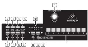
(1) TEMPO/GATE LENGTH – this knob controls the sequencer and arpeggio tempo. During step editing, it also controls the GATE length. If SHIFT is held, then the knob also adjusts the SWING.
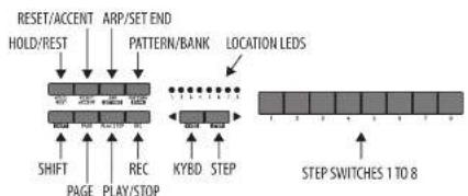
☐ HOLD/REST – during pattern playback, this allows you to hold the current step. During step editing, it allows you to enter a rest.
③ RESET/ACCENT – during playback, this allows you to reset the pattern back to step 1. During step editing, you can add an accent to a step.
[4] ARP (SET END) — press ARP and play any keys, to create an arpeggio. Press HOLD and ARP to hold the arpeggio. In Sequencer mode, pressing SHIFT and SET END together, followed by a STEP switch, will allow that stop to become the end of the current pattern.
5 PATTERN (BANK) — This switch is used to access either the current pattern, or bank number, as follows:
PATTERN: Press PATTERN, and one of the 8 LOCATION LEDs will show the current pattern number (from 1 to 8). To change to a different pattern number, keep the PATTERN switch held down and press any of the STEP switches (1 to 8), or press
BANK: Press SHIFT and PATTERN, and one of the 8 LOCATION LEDs will show the current bank number (from 1 to 8). To change to a different bank number, keep both SHIFT and BANK held down, and press any of the STEP switches (1 to 8), or press
(1) SHIFT - This is used to access the secondary features of some of the other sequencer controls, such as SET END, BANK, SWING, KYDB, and STEP. Hold down SHIFT and the other switch at the same time. For example SHIFT + PATTERN (BANK) will show the current BANK number to the 16CATHL FPs
[7] PAGE - each pattern can be up to 32 steps in length. This switch allows you to show each of the 4 pages of B steps each. The LOCATION LEDs 1 to 4, show which page you are on. If a pattern is playing, the STEP LEDs will show the steps in use on the current page.
PLAY/STOP – starts or stops the playback of the pattern. If SHIFT is held at the same time, then this is the start of the pattern saving procedure, described below.
☐ REC – press this to begin the recording of a new pattern. This is also used with SHIFT during the pattern saving procedure.
☐ LOCATION – these multi-colored LEDs show various details, such as the current PATTERN number, current BANK number, current PAGE, and GATE LENGTH.
11 KYBD - press SHIFT + IYBD to change the sequencer to keyboard mode.
[13] STEP – press SHIFT + STEP to change the sequencer to STEP mode.
STEP SWITCHES – these multi-function switches allow you to view and select individual pattern steps, select a pattern number, select a pattern bank. They are used during recording of a pattern to show the current step. Active steps are illuminated with a steady red LED, and the current step flashes red.
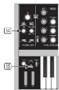
[14] GLIDE KNOB – during step editing, this knob can be used to add a Ratchet by splitting the current step into 1, 2, 3, or 4 parts. Hold down SHIFT and turn the knob to split the current step into the number of parts shown by the LOCATOR LEDs [yellow] 1 to 4.
15 GLIDE SWITCH – the GLIDE switch does not have to be on for the Ratchet to work.
POLY D Controles
ES Paso 2: Controles
Sección de Teclado
Section Oscillator Bank
POLY D Controlli POLY D Bediening
NL Stap 2: Bediening
Toetsenbordgedeelte
NL Stap 2: Bediening
POLY D Getting started
EN Step 3: Getting started
OVERVIEW
This 'getting started' guide will help you set up the POLY D analog synthesizer and briefly introduce its capabilities.
CONNECTION
To connect the POLY D to your system, please consult the connection guide earlier in this document.
SOFTWARE SETUP
The POLY D is a USB Class Compliant MIDI device, and so no driver installation is required. The POLY D does not require any additional drivers to work with Windows and MacOS.
The "Synthtool.exe" application allows you to select the MIDI channel number and to set and adjust various parameters of the POLY D to suit your preferences. SysEx commands can also be used. Please see the information later in this manual.
HARDWARE SETUP
Make all the connections in your system.
Apply power to the POLY D using the supplied power adapter only. Ensure your sound system is turned down. Turn on the POLY D power switch.
WARM UP TIME
We recommend leaving 15 minutes or more time for the POLY D to warm up before recording or live performance. (Longer if it has been brought in from the cold.) This will allow the precision analog circuits time to reach their normal operating temperature and tuned performance.
MIXER SECTION
The POLY D has four oscillators, an internal Noise generator, and an external source input. Each of these, and any combination, are used by the POLY D to generate sound.
The Mixer section allows you to turn each of these sources on or off, and adjust the volume of each to create an overall mix. Start by turning on the top switch for Oscillator 1, and turn off the others. Adjust the volume control of Oscillator 1. In the Output section, adjust the main volume. Now, if you play a note on your keyboard, you should hear the sound of Oscillator 1 only.
Turn on other oscillators and/or noise and adjust their volume controls to create a mix.
If the MODE switch is set to PCLY, the first note will play Oscillator 1, playing 2 notes plays Oscillator 1 and 2, playing 3 notes plays Oscillator 1, 2, and 3, and playing 4 notes plays Oscillator 1, 2, 3, and 4.
OSCILLATOR SECTION
In the Oscillator section, adjust the Range knob and you will hear the sound of the various octaves. Adjust the wavetype and listen to the differences.
The oscillator modulation switch allows the oscillator frequency to be modulated by the modulation mix. The OSC 4 switch allows its frequency to be affected by, or be independent of, the notes played on the keyboard, and the modulation and pitch wheels. Note: The TUNE knob and OSCILLATOR 2, 3, and 4 FREQUENCY knobs are marked in units of semi-tomes as a general guide.
FILTER SECTION
Play with the Cutoff Frequency, Emphasis, and Contour, and listen to their effects on the sound. Adjust the Attack, Decay, and Sustain; they affect the cutoff frequency with time, while a note is played.
The 2 keyboard switches affect how much the filter is affected by the frequency of notes that are players. If the filter modulation switch is ON then the filter section is modulated by the modulation mix.
LOUDNESS CONTOUR SECTION
In this section, adjust the Attack, Decay, and Sustain; they affect the overall level with time, while a note is played. The loudness decay switch affects the decay in level after a note is released.
CONTROLLERS SECTION
First set the 2 switches to choose from internal LFO or internal Noise, OSC 4 or the filter envelope, and then use the MODULATION MIX knob to vary the mix between them.
You can experiment by first setting the switch to OSC 4, and turning the MODULATION MIX knob to OSC 4. Then set the Oscillator 4 range control to LO, and the Oscillator Modulation switch OK. You may now be able to hear the sound of the Oscillator 1 modulated by OSC 4. Use the Modulation wheel of your keyboard to increase the effect.
If the Filter Modulation switch is ON, listen to the effect of modulation on the filter.
The Modulation Sensitivity curve can be chosen from hard, medium, or soft (the default), using the SysEx commands shown later in this manual.
SEQUENCER SECTION
Details of the Sequencer operation are shown on page 38.
ARPEGGIATOR
To use the arpeggiator, press the ARP switch in the sequencer section:
- Press it once to play the arpeggiator. (It stops when notes are released.)
- Press HOLD to play and hold the arpeggiator. (It continues when notes are released.)
The arpeggiator rate is set by the TEMPO/GATE LENGTH knob.
The order in which the arpeggiator notes are played has 8 options, and this can be changed by pressing either
-
UP (+10CT)
-
DOWN (+10CT)
-
UP (-1 OCT)
-
DOWN (-1 OCT)
FIRMWARE UPDATE
Please check our website behlinger.com regularly for any updates to the firmware of your POLY D synthesizer. The firmware file can be downloaded and stored on your computer, and then used to update the POLY D. It comes with detailed instructions on the update procedure.
HAVE FUN
The POLY D has various Gate and CV Inputs and outputs that allow for further experimentation and expansion to other POLY D units and modular synthesizer equipment.
Make copies of the patch sheet at the end of this manual, and record your favorite settings.
With all these controls, the possibilities for musical creativity are endless, rather like an artist with a new box of paints. We hope that you will enjoy your new POLY D.
-
UP
-
DOWN
-
DOWN and UP
-
RANDOM
-
UP (+10CT)
-
DOWN (+1 OCT)
-
UP [-TOCT]
-
DOWN (-1 OCT)
-
UP 1
-
DOWN 1
-
DOWN and UP
-
RANDOM
-
UP (+1 OCT)
-
DOWN(+10CT)
-
UP (-1 OCT)
-
DOWN (-1 OCT)
POLY D Sequencer Operation
EN Sequencer Operation
flowchart
graph TD
    A["RESET/ACCENT"] --> B["HOLD/REST"]
    B --> C["ARP/SET END"]
    C --> D["PATTERN/BANK"]
    D --> E["LOCATION LEDS"]
    E --> F["STEP SWITCHES 1 TO 8"]
    F --> G["KYBD STEP"]
    G --> H["REC"]
    H --> I["PAGE PLAY/STOP"]
    I --> J["SHIFT"]
    J --> K["PAGE"]
SEQUENCER OVERVIEW
The following details show some of the basic operation of the sequencer. You can create a short pattern of 2 or 3 steps, before trying more complex patterns. Adjust a single parameter at a time, such as gate length, ratchet, accent, glide, rest, tie, or swing, and then listen to its effect during playback.
It will help to choose a simple setting for the synthesizer, such as only one source, and no modulation of the VCO or VCF.
RECORDING A SIMPLE PATTERN
- Press SHIFT and <KYBD to select the keyboard mode.
- Initialise the current pattern by pressing SHIFT, RESET, and PATTERN at the same time. This will delete any previous steps of the current pattern.
- Press REC, and the STEP 1 switch LED will begin flashing, indicating this is the current step about to be added and edited. (If you cannot select REC, then repeat step 1.)
- Press any note on the keyboard, or a rest as shown below.
- To enter a rest instead of a note, press the HOLD/REST switch. When a rest is added, the LOCATOR LED 8 will light.
- Press further notes. The next STEP switch LED will be flashing after each note or rest has been added.
-
The gate length of a step can be adjusted using the TEMPO/SATE LENGTH control. The LOCATOR LEDs will turn red, showing the gate length from 1 to 8. If set to 8, this creates a tie with the next step, if the next step is the same note, this creates a longer note, as the 2 steps are tied.
-
To create a "Ratchet," hold SHIFT, and turn the GUIDE control. The locator LEDs will show the number of ratchets from 7 to 4, in yellow. For example, with a setting of 4, the single step is split into 4 equal parts. When a ratchet is applied, the LOCATION LED 6 will light.
-
To turn the GLIDE on for a step, turn up the GLIDE control. To turn off, turn it all the way down. When GLIDE is on for a step, the LOCATION LED 5 will light.
-
To increase the brightness or accent, press the RESET/ACCENT switch. When an accent is applied, the LOCATION LED 7 will light.
-
Press REC when you have finished creating the pattern. It is not saved yet, but it can be played back. Caution: Do not turn off the unit, or create a new pattern, or the current unsaved pattern will be lost.
PLAYING A PATTERN
- Press PLAY/STOP to listen to the current pattern.
- If you decide not to save it, you can repeat the recording steps above to record a new pattern. Alternatively, press PATTERN and RESET to recall the currently saved pattern, and discard any changes.
- If you decide to save the pattern, you must follow the "SAVING A PATTERN" procedure shown below, or it will not remain in memory if a new pattern is begun, or the power is turned off.
-
To create a SWING for this pattern, hold SHIFT and adjust the TEMPO/GATE LENGTH control. In the center position, no swing is applied, if turned down, only the off-beats will play, and if all the way up, only the on-beats will play. The SWING setting for the pattern is saved when the pattern is saved as shown below.
-
While playing a pattern:
Press HOLD/REST to hold the current step. Press RESET/ACCENT to return to step 1.
Press SHIFT and any STEP, and you can edit the gate length, rest, accent, ratchet, glide but not note. Press SHIFT and the same STEP again to exit step edit. If playback is paused, the same operation can edit the note as well.
Press PAGE to view the pattern page from 1 to 4. Press SHIFT and PAGE to return to automatic page turning. Press SHIFT and ARP/SETEND and a STEP to
PLAY/STOP to pause playback.
- Press PLAY/STOP.
SAVING A PATTERN
- Press and hold SHIFT + PLAY/STOP for 2 seconds until the LOCATOR LED of the current pattern number begins to flash green slowly.
- Press a STEP switch 1 to 8 to select the new desired pattern number.
- Press PATTERN + STEP switch 1 to 8 to select the desired bank number.
- Press SHIFT + REC to save the pattern and exit the save mode.
RECALLING A SAVED PATTERN
- Press and hold PATTERN. The LOCATION LED will show the current pattern number. Use the
switches to move up and down through the patterns 1 to 8, or press a STEP switch 1 to 8. You can also do this while a pattern is playing. - Press and hold SHIFT and PATTERN. The LOCATION LED will show the current bank number. Use the
switches to move up and down through the banks 1 to 8, or press a STEP switch 1 to 8. You can also do this while a pattern is playing. - Press PLAY/STOP to play back the current pattern.
- During playback, the LOCATION LEDs will show the current page of the pattern (1 to 4), and the STEP Switch LEDs will show the steps moving.
LIVE PERFORMANCE
During playback, temporary adjustments can be made as follows. (None of these are saved with the pattern.)
1. To add Ratchet to all steps of the pattern, press SHIFT and adjust the GLIDE control.
2. To add SWING, press SHIFT and adjust the TEMPO control.
3. To mute the pattern, press SHIFT + HOLD/REST.
4. To add an accent to all steps, press SHIFT + RESET/ACCENT.
EDITING A PATTERN
- To edit a pattern in Keyboard mode, press REC. The STEP switch LEDs will light.
- Press PAGE to select the pattern page from 1 to 4 to be edited. The green LOCATION LEDs 1 to 4 will show the current page.
- Press SHIFT and the STEP switch you want to edit. You can enter a new note, or a rest, and adjust any of the other parameters such as ratchet, glide on/off, and so on.
- Press SHIFT and the next STEP switch to be edited. (The steps will not automatically advance to the next step in line; you can choose which steps to edit next.)
- Press REC to exit the editing mode.
-
Press PLAY/STOP to listen to the edited pattern.
-
Remember to save the pattern using the "SAVING A PATTERN" procedure above.
CREATING A PATTERN IN STEP MODE
- Press SHIFT and STEP> to select the Sequencer's STEP mode. The flashing LOCATION LED will turn from green (Keyboard mode) to yellow (Stop mode).
- Initialise the current pattern by pressing SHIFT, RESET, and PATTERN at the same time. This will delete any previous steps of the current pattern. (If you want to use the current pattern instead, then do not initialise it.)
- Press PAGE to move to a desired page of your pattern. Then press SET END and a STEP switch to choose the length of the pattern. For example, if you are on page 1 and press SET END + 8, then the pattern length is 8 steps. If you press PAGE and reach page 4, and press SET END + 8, then the pattern will be 32 steps long (4 pages of 8 steps each).
- When the desired SET END is selected, all the STEP switch LEDs up to that step will be on solid red.
- Press SHIFT and any one of the STEP switches at the same time. It will begin to flash, indicating it is the current step about to be edited. You can now add a note, or a rest, or any of the other functions described above in the Keyboard mode, such as Batchet, Glide, Accent, change gate length and so on.
- Press SHIFT and the current STEP switch to finish editing that step. It will stop flashing.
- Repeat procedure steps 5 and 6 above, until all your required steps are good.
- Press PLAY/STOP to play the pattern
- While playing, you can add temporary adjustments as shown in the "LIVE PERFORMANCE" procedure above.
SAVING A PATTERN IN STEP MODE
- Patterns created in STEP mode are not saved in this mode.
- If you wanted to save it, first switch back to KEYBOARD mode by pressing SHIFT + <KYBD.
- Caution: Do not turn off the unit, or create a new pattern, or the current unsaved pattern will be lost.
- Save the pattern using the "SAVING A PATTERN" procedure shown above for the KEYBOARD mode.
POLY D Sequencer-bediening
MINNER OM ETT SPARAD MÖNSTER
The "Synthool.exe" application allows you to select the MIDI channel number and to set and adjust various parameters of the POLY D to suit your preferences.
Parameters can also be accessed via MIDI system Exclusive (SysEx) commands. Please see the information shown below.
SETTING VALUES VIA SYSEX
Use the following data format to set global value using a SysEx message.
10 00 20 32 00 01 0c au bou D0 ... Dn F7
00 20 32 = Manufacture SYSEX ID number (Behringer GmbH)
00 01 0c = Model ID for POLY D
sa = Device ID: 00-0x7F (must match hardware device ID), or 0x00 to address all devices.
bb = Packet number
cc = Sub packet number (maybe absent for some message).
DO..Dn = Packet payload
COMMAND TABLE
| Packet Number | Sync Packet | Functions | Note | Default |
| 10 | 10:20:32:00:01 1c:30:55 mm f7 | Set check bit (D0) | m = 100 to set, range from ( 0 - 121,0 - = avg) | [1] |
| 11 | F01:20:32:00:01 1c:30:06 15 mm mm F2 | Set mid channel | m = Mid 74 channel number/box set, range from [0, 16], 0 – Any channel. m = Mid 82 channel number to best, range from [0, 16], 1 – Any channel. Detail value. [1] | [1] |
| 12 | 10:30:32:00:01 1c:30:01 mm f7 | Set MCHB Transcope | m = transcope value [0-20]. Transport range 0 - 12 to 1 + 12 , so 12 is noncompose. Detail value. [1] | [1] |
| 13 | 10:30:32:00:01 1c:30:12 mm pp f7 | Set velocity hits | m = Key velocity rate on, 1 - 121 is fixed value of velocity. Full dynamic velocity m = Key velocity rate on, 1 - 121 is a fixed value of velocity; Full dynamic velocity. p = safety curve 0 - f , 1 - and 2 - hard | m = 1 \ 0 \ 0 \ 0 \ 0 \ 0 \ 0 \ 0 \ 0 \ 0 \ 0 \ 0 \ 0 \ 0 \ 0 \ 0 \ 0 \ 0 \ 0 \ 0 \ 0 \ 0 \ 0 \ 0 \ 0 \ 0 \ 1 |
| 14 | 10:30:32:00:01 1c:30:14 mm mm f7 | Set pitch bend range | m = Pitch bend range [0-21], 0 - 2 cutave, lgrone mm | [12-14 above] |
| 15 | F01:20:32:00:01 1c:30:15 mm f7 | Set key priority | ft low 1,ft high ,2 end | [1 below] |
| 16 | 10:30:32:00:01 1c:30:16 mm f7 | Set mid profile | m = mid-range [0-20], 1-mod, 2-end lgrone mm | m = m = 1 - 1 , m = 1 |
| 17 | F01:20:32:00:01 1c:30:17 mm f7 | Set the NOD clock output | m = curve [0 soft, 1 Mod, 2 hard] | [0 - sub] |
| 18 | F01:20:32:00:01 1c:30:19 mm f7 | Set external clock priority | [2-27] | [124-22] |
| 19 | F01:20:32:00:01 1c:30:14 mm f7 | Set sync clock rate | m = 0 - 10 P,1 - 10 P,2 - 10 P,3 - 10 P P | [3-500M] |
| 20 | F01:20:32:00:01 1c:30:18 mm f7 | Set sync clock source | m = 0 - 10 P,1 - 10 P,2 - 10 P,3 - 10 P P | [1-450K] |
| 21 | F01:20:32:00:01 1c:30:21 mm f7 | Verification window range | m = 0 - 10 P,1 - 10 P,2 - 10 P,3 - 10 P | [2-24PPQ] |
| 22 | F01:20:32:00:01 1c:30:22 mm f7 Set mid output of | shift threshold | m = 0 - 10 P,1 - 10 P,2 - 10 P,3 - 10 P | [3-500M] |
| 23 | F01:20:32:00:01 1c:30:23 mm f7 Set mid output of | of legendd | m = 0 - 10 P,1 - 10 P,2 - 10 P,3 - 10 P | [3-500M] |
| 24 | F01:20:32:00:01 1c:30:24 mm f7 | Set mid output of segmented after each responseer | m = 0 - 10 P,1 - 10 P,2 - 10 P,3 - 10 P | [3-500M] |
| 25 | F01:20:32:00:01 1c:30:25 mm f7 Set mid output of | put of anti-gulator | m = 0 - 10 P,1 - 10 P,2 - 10 P,3 - 10 P | [3-500M] |
| 26 | F01:20:32:00:01 1c:30:26 mm f7 Set binding | Reston factory settings |
Quick Star Guide 73
POLY D System Exclusive Data Sheet
The "Synthroolex" application allows you to select the MIDI channel number and to set and adjust various parameters of the POLY D to suit your preferences. Parameters can also be accessed via MIDI system Exclusive (SysEx) commands. Please see the information shown below.
SETTING VALUES VIA SYSEX
Use the following data format to set global value using a SysEx message.
F0 00 20 32 00 01 0c aa bb cc D0 ... Dn F7
00 20 32 = Manufacture SYSEX ID number (Behringer GmbH)
00-01 0c = Model ID for POLY D
aa = Device ID: 00-Dx7F (must match hardware device ID),
or 0x00 to address all devices.
bb = Packet Number
cc = Sub packet number (maybe absent for some message).
DD..On = Packet payload
| Synthesis Architecture | |
| Number of voices | Monoplastic / unison / polyphonic (10 choices), switched |
| Type Analog | |
| Oscillators | 4 (0.1 Hz to 20 kHz, 6 overlapping ranges) |
| LFO 1 (0.05 Hz to 200 Hz) | |
| VCF | 1 x low / high pass filter, switched, 24 dB/arc, slope |
| Envelopes | VCA, VCF |
| MHz channel's | 16 |
| Connectivity | |
| MHz in / out-thru | 5-star DR |
| USB (8000) | type5 |
| Main output | 2x 3/4" TS, serum balanced |
| Max output level | -16 dBu |
| Impedance | 100 Ω |
| External signal input | 9/4" TS, unbalanced |
| Impedance | 1 MΩ |
| External v-tagger input | 1 x 3/4" TS, unbalanced, +5 V |
| Sync 2 x 3/4" TS, input and output, unbalanced, +5 V | |
| Headphones | 1 x 3/4" IRS, stereo |
| Max output level | -4 dBu |
| Output impedance | 110 Ω |
| External Control Inputs | |
| Loudness | 1 x 3/4" TS, unbalanced, 0 to +5 V |
| Filler | 1 x 3/4" TS, unbalanced, 0 to +5 V, 1 W/dL |
| Cofactor | 1 x 3/4" TS, unbalanced, ±5 V |
| Modulation source | 1 x 3/4" TS, unbalanced |
| Internal control outputs | |
| After pressure | 1 x 3/4" TS, unbalanced, 0 to +5 V |
| Pitch | 1 x 3/4" TS, unbalanced, 3 to +7 V |
| V-trigger | 1 x 3/4" TS, unbalanced, +5 V |
| Velocity | 1 x 3/4" TS, unbalanced, 0 to +5 V |
| Controls Section | |
| Knits | Timer: 2 to +2, adjustable |
| Slice: 0 to 10, adjustable | |
| Modulation mode: USC 4 / filter ES to (not rated, mod source / LFO), adjustable | |
| Switches | Modulation source: USC 4 / filter ES |
| Modulation source: noise or external modulation source / LFO | |
| Mode: mono / unison / poly | |
| Auto Rating on / off | |
| Recline Section | |
| Kinds | Range (OSC 1, 2, 3, and 4): 10 / 32 / 16 / 8 / 4 / 25, selectable |
| Frequency (OSC 2, 3, and 4) - 2 to 17, adjustable | |
| Waveform (OSC 1, 2, and 3): triangular / triangular saw / saw / square / wide pulse, narrow pulse, selectable | |
| Waveform (OSC 4): triangular / reverse saw / saw / square / wide pulse / narrow pulse, selectable | |
| Switches | Oscillator modulation on / off |
| OSC 4 control (by keyboard) on / off | |
| Outer Section | |
| Kinds | Volume (OSC 1, 2, 3, and 4): 0 to 10, adjustable |
| Volume (external input): 0 to 10, adjustable | |
| Volume (noise): 0 to 10, adjustable | |
| Switches | OSC 1, 2, 3, and 4: on / off |
| External input: on / off | |
| Noise: on / off | |
| Noise source: pink / white | |
| Indicators | Overload LED |
| Filter Section | |
| Kinds | Cutoff frequency: -4 to +4, adjustable |
| Filter emphasis: 0 to 10, adjustable | |
| Amount of contour: 0 to 10, adjustable | |
| Attack: 1 ms to 10 s, adjustable | |
| Decay: 4 ms to >35 s, adjustable | |
| Sustam: 0 to 10, adjustable | |
| Switches | Filter mode: low pass / high pass |
| Filter modulation on / off | |
| Keyboard control: 0 or 1(1)/ off | |
| Keyboard control: 2: on (2/3) / off | |
| Leadmax Counter Section | |
| Kinds | Amount of contour: 0 to 10, adjustable |
| Attack: 1 ms to 10 s, adjustable | |
| Decay: 4 ms to >35 s, adjustable | |
| Switch | Decay: on / off |
| Distortion Section | |
| Kinds | Distortion: 0 to 10, adjustable |
| Tone: 0 to 10, adjustable | |
| Level: 0 to 10, adjustable | |
| Switches Distortion on / off | |
| Chorus Section | |
| Switches | Chorus I: on / off |
| Chorus II: on / off | |
| Chorus I on / off | |
| LED Chorus I, Chorus II | |
| Output Section | |
| Kneds | Volume: 0 to 10, adjustable |
| Headphone volume: 0 to 10, adjustable | |
| Switches Power on / off | |
| LED Power | |
| Sequence Section | |
| Number of steps 5/2 steps max./bottom | |
| Number of patterns 6/4 patterns max. | |
| Memory storage 8 banks | 8 pattern sbank |
| Kneds Tempo / quite length / swing | |
| Switches | Hold / rest |
| Reset / accent | |
| Amp / set end | |
| Pattern / blank | |
| Shift | |
| Page | |
| Play / step | |
| Record | |
| Keyboard mode | |
| Step mode | |
| LED B's location | 10 x double switches |
| LIFO Section | |
| Knife LFO rate 0 to 10, adjustable | |
| Switches LFO waveform: triangular / square | |
| LED LFO rate | |
| Keyboard and Controls | |
| Wheels Pitch | Production |
| Switchers Glide on / off | Transpose up / down 1 active |
| Keyboard 32, semi-angloph, full-size keys with velocity | |
| USB | |
| type Class-compliant USB 2.0, type B | |
| Supported operating systems | Windows XP or higher |
| After OS X 10.5.8 or higher | |
| Power Requirements | |
| External power adaptor 12 VDC 1000 mV | |
| Power consumption | 10 W max. |
| Environmental | |
| Operating temperature range | 5°C - 40°C (41°F - 104°F) |
| Physical | |
| Dimensions (ft x 10 x 10) | 50 x 648 x 361 mm (3.5 x 25.5 x 14.2") |
| Weight | 10.2 kg (22.5 lbs) |
EN
Other important information
EN Important information
- Register online. Please register your new Music Tribe equipment right after you purchase it by visiting muscibe.com. Registering your purchase using our simple online form helps us to process your repair claims more quietly and efficiently. Also, read the terms and conditions of our warranty, if applicable.
- Malfunction, Should your Music Tribe Author and Reseller not be located in your vicinity, you may contact the Music Tribe Authorized Fulfill for your country listed under "Support" at musicitibe.com. Should your country not be listed, please check if your problem can be dealt with by our "Online Support" which may also be found under "Support" at musicitibe.com. Alternatively, please submit an online warranty claim at musicitibe.com BEFORE returning the product.
- Power Connections. Before plugging the unit into a power socket, please make sure you me using the correct mains voltage for your particular model. Equity fuses must be replaced with fuses of the same type and rating without exception.
Responsible Party Name: Music Tribe Commercial NV Inc.
Address: 5270 Procyon Street,
Las Vegas NV 89118,
United States
Phone Number: +1 702 800 8290
POLY D
This equipment has been tested and found to comply with the limits for a Class B digital device, pursuant to part 15 of the FCC Rules. These limits are designed to provide reasonable protection against harmful interference in a residential installation. This equipment generates, uses and can radiate radio frequency energy and, if not installed and used in accordance with the instructions, may cause harmful interference to radio communications. However, there is no guarantee that interference will not occur in a particular installation. If this equipment does cause harmful interference to radio or television reception, which can be determined by turning the equipment off and on, the user is encouraged to try to correct the interference by one or more of the following measures:
- Reorient or relocate the receiving antenna.
- Increase the separation between the equipment and receiver.
- Connect the equipment into an outlet on a circuit different from that to which the receiver is connected.
- Consult the dealer or an experienced radio/TV technician for help.
This device complies with Part 15 of the FCC rules. Operation is subject to the following two conditions:
(1) this device may not cause harmful interference, and (2) this device must accept any interference received. Including interference that may cause undesired operation.
Important information:
Changes or modifications to the equipment not expressly approved by Music Tribe can void the user's authority to use the equipment.
CE
Hereby, Music Tribe declares that this product is in compliance with Directive 2014/35/EU/Directive 2014/30/EU, Directive 2011/65/EU and Amendment 2015/863/EU, Directive 2012/19/EU, Regulation 519/2012 REACH SVHC and Directive 1907/2006/EC. Full text of EU DoC is available at https://community.musictribe.com/ EU Representative: Music Tribe Brands DK A/S Address: Ib Spang Discens Gede 17, DK - 8200 Aarhus N, Denmark
We Hear You
- LEGAL DISCLAIMER
- LIMITED WARRANTY
- BESCHRÄNKTE GARANTIE
- POLY D Hook-up
- POLY D Controls
- Keyboard Section
- Controllers Section
- Oscillator Bank Section
- Mixer Section
- EN Step 2: Controls
- Chorus Section
- Distortion Section
- Output Section
- Rear Panel
- Sequencer Section
- POLY D Controles
- ES Paso 2: Controles
- Sección de Teclado
- Section Oscillator Bank
- POLY D Controlli POLY D Bediening
- NL Stap 2: Bediening
- Toetsenbordgedeelte
- POLY D Getting started
- EN Step 3: Getting started
- OVERVIEW
- CONNECTION
- SOFTWARE SETUP
- HARDWARE SETUP
- WARM UP TIME
- OSCILLATOR SECTION
- FILTER SECTION
- LOUDNESS CONTOUR SECTION
- ARPEGGIATOR
- FIRMWARE UPDATE
- HAVE FUN
- POLY D Sequencer Operation
- SEQUENCER OVERVIEW
- RECORDING A SIMPLE PATTERN
- PLAYING A PATTERN
- SAVING A PATTERN
- RECALLING A SAVED PATTERN
- LIVE PERFORMANCE
- EDITING A PATTERN
- CREATING A PATTERN IN STEP MODE
- SAVING A PATTERN IN STEP MODE
- POLY D Sequencer-bediening
- MINNER OM ETT SPARAD MÖNSTER
- SETTING VALUES VIA SYSEX
- POLY D System Exclusive Data Sheet
- Other important information
- EN Important information
- POLY D
- CE
Brand : BEHRINGER
Model : Poly D
Category : Synthesizer