YM90 - Grass trimmer Yard-Man - Free user manual and instructions
Find the device manual for free YM90 Yard-Man in PDF.
| Product type | Trimmer / Weed cutter / Brush cutter |
| Brand | Yard-Man |
| Model | YM90 |
| Engine | 2-stroke, air-cooled, 31 cc (1.9 cu in) |
| Displacement | 31 cc |
| Fuel | Unleaded gasoline/oil mixture, ratio 40:1 |
| Fuel tank capacity | 384 ml (13 oz) |
| Clutch | Centrifugal |
| Idle speed | 2,800 – 4,400 rpm |
| Operating speed | 7,200 rpm and above |
| Ignition | Electronic |
| Spark plug | Champion RDJ7Y, gap 0.5 mm |
| Starting | Automatic rewind with EZ-Start™ system |
| Cutting attachment type | Bump Head™ dual line head (2.41 mm) or 4-tooth blade |
| Cutting diameter (line) | 45.7 cm (18 in) |
| Cutting diameter (blade) | 20.4 cm (8 in) |
| Drive shaft | Steel, EZ-Link™ system with coupler |
| Handle | Adjustable J-handle |
| Harness | Shoulder harness with quick-release buckle |
| Weight (empty) | 6.35 kg (14 lb) |
| Protection | Cutting attachment guard, spark arrestor |
| Maintenance | Air filter cleaning every 10 h; spark plug and spark arrestor every 25 h |
| Warranty | 2 years (parts and labor); emissions warranty 2 years |
Frequently Asked Questions - YM90 Yard-Man
User questions about YM90 Yard-Man
0 question about this device. Answer the ones you know or ask your own.
Ask a new question about this device
Download the instructions for your Grass trimmer in PDF format for free! Find your manual YM90 - Yard-Man and take your electronic device back in hand. On this page are published all the documents necessary for the use of your device. YM90 by Yard-Man.
USER MANUAL YM90 Yard-Man
natural_image
Technical line drawing of a metal detector with attached components (no text or symbols)2-Cycle Trimmer/Brushcutter
Model YM90

text_image
MTD For A Growing World.IMPORTANT: Read safety rules and instructions carefully before operating equipment.
TABLE OF CONTENTS
Content Page
Rules for Safe Operation ....3
Know Your Trimmer ....7
Assembly Instructions 8
Oil and Fuel Information 11
Starting/Stopping Instructions 12
Operating Instructions 13
Maintenance and Repair Instructions ....16
Cleaning and Storage 21
Troubleshooting 22
Specifications....23
Warranty 26
Parts List .......Inside Back Cover
FINDING MODEL NUMBER
This Operator's Manual is an important part of your new trimmer. It will help you assemble, prepare and maintain the unit for best performance. Please read and understand what it says.

Before you start assembling your new equipment, please locate the model plate on the unit and copy the information from it onto the space provided below. The information on the model plate is very important if you need help from our Customer Support Department or an authorized dealer.
- The model number is located on the engine. A sample model plate is shown and explained below. For future reference, please copy the model number and the serial number of the equipment in the space provided.

text_image
Serial Number Model Number MODEL : S/N : ITEM : Parent Part NumberCopy the model and parent
part number here:
Copy the serial number here:
CALLING CUSTOMER SUPPORT
If you have difficulty assembling this product or have any questions regarding the controls, operation or maintenance of this unit, please call the Customer Support Department.
Call 1- (800)-345-8746, or 1- (800)-668-1238 in Canada, to reach a Customer Support representative.
Please have your unit's model number and serial number ready when you call. You will be asked to enter the serial number in order to process your call. This information is explained above.
VISIT OUR WEB SITE
Visit our web site at www.yardman.com for more information about our quality Yard Man products, customer service, parts, tips, literature and more.
SPARK ARRESTOR
NOTE: For users on U.S. Forest Land and in the states of California, Maine, Oregon and Washington. All U.S. Forest Land and the state of California (Public Resources Codes 4442 and 4443), Oregon and Washington require, by law that certain internal combustion engines operated on forest brush and/or grass-covered areas be equipped with a spark arrestor, maintained in effective working order, or the engine be constructed, equipped and maintained for the prevention of fire. Check with your state or local authorities for regulations pertaining to these requirements. Failure to follow these requirements could subject you to liability or a fine. This unit is factory equipped with a spark arrestor. If it requires replacement, ask your LOCAL SERVICE DEALER to install the accessory part #182747 Spark Arrestor.
WARNING!
Read the Operator's Manual and follow all warnings and safety instructions. Failure to do so can result in serious injury to the operator and/or bystanders.
FOR QUESTIONS, CALL 1-800-345-8746 IN U.S. OR 1-800-668-1238 in CANADA
SECTION 1: IMPORTANT SAFE OPERATION PRACTICES

The purpose of safety symbols is to attract your attention to possible dangers. The safety symbols and their explanations deserve your careful attention and understanding. The safety warnings do not by themselves eliminate any danger. The instructions or warnings they give are not substitutes for proper accident prevention measures.

SAFETY ALERT SYMBOL: Indicates danger, warning, or caution. Attention is required in order to avoid serious personal injury. May be used in conjunction with other symbols or pictographs.
NOTE: Advises you of information or instructions vital to the operation or maintenance of the equipment.

DANGER: Failure to obey a safety warning will result in serious injury to yourself or to others. Always follow the safety precautions to reduce the risk of fire, electric shock and personal injury.

WARNING: Failure to obey a safety warning can result in injury to yourself and others. Always follow the safety precautions to reduce the risk of fire, electric shock and personal injury.

CAUTION: Failure to obey a safety warning may result in property damage or personal injury to yourself or to others. Always follow the safety precautions to reduce the risk of fire, electric shock and personal injury.
SECTION 1a:RULES FOR SAFE OPERATION
California Proposition 65 Warning:

WARNING

THE ENGINE EXHAUST FROM THIS PRODUCT CONTAINS CHEMICALS KNOWN TO THE STATE OF CALIFORNIA TO CAUSE CANCER, BIRTH DEFECTS OR OTHER REPRODUCTIVE HARM.
READ ALL INSTRUCTIONS

WARNING: When using the unit, you must follow the safety rules. For your own safety and that of bystanders, please read these instructions before operating the unit. Please keep the instructions for later use.
Before Operating
- Read the instructions carefully. Be familiar with the controls and proper use of the unit.
- Do not operate this unit when tired, ill or under the influence of alcohol, drugs or medication.
- Children under the age of 15 must not use the unit; teens may operate the unit with adult guidance.
- Inspect the unit before use. Replace damaged parts. Check for fuel leaks. Make sure all fasteners are in place and secure. Replace cutting attachment parts that are cracked, chipped or damaged in any way. Make sure the cutting attachment is properly installed and securely fastened. Be sure that the cutting attachment shield is properly attached, and positioned as recommended. Failure to do so can result in personal injury to the operator and bystanders, as well as damage to the unit.
- Use only 0.095-inch (2.41 mm) diameter Genuine Factory Parts™ replacement line. Never use metal-reinforced line, wire, chain or rope. These can break off and become dangerous projectiles.
- Be aware of risk of injury to the head, hands and feet.
- Clear the area to be cut before each use. Remove rocks, broken glass, nails, wire, string and other objects which may be thrown or become entangled in the cutting attachment. Clear the area of children, bystanders and pets; keep them outside a 50-foot (15 m.) radius, at a minimum. Even then, they are still at risk from thrown objects. Encourage bystanders to wear eye protection. If you are approached, stop the unit immediately.
- Squeeze the throttle control and check that it returns automatically to the idle position. Make all adjustments or repairs before using the unit.
Safety Warnings for Gas Trimmers

WARNING: Gasoline is highly flammable, and its vapors can explode if ignited. Take the following precautions:
- Store fuel only in containers specifically designed and approved for the storage of such materials.
- Always stop the engine and allow it to cool before filling the fuel tank. Never remove the fuel tank cap or add fuel when the engine is hot. Never operate the unit without the fuel cap securely in place. Loosen the fuel tank cap slowly to relieve any pressure in the tank.
- Add fuel in a clean, well-ventilated outdoor area where there are no sparks or flames. Remove the fuel cap slowly, and only after the engine stops. Do not smoke while fueling or mixing fuel. Wipe up any spilled fuel from the unit immediately.
- Avoid creating a source of ignition for spilled fuel. Do not start the engine until fuel vapors dissipate.
- Move the unit at least 30 feet (9.1 m) from the fueling source and site before starting the engine. Do not smoke. Keep sparks and open flames away from the area while adding fuel or operating the unit.
While Operating
- Never start or run the unit inside a closed room or building. Breathing exhaust fumes can be fatal. Operate this unit only in a well-ventilated outdoor area.
- Wear safety glasses or goggles that meet ANSI Z87.1 standards and are marked as such. Wear ear/hearing protection when operating this unit. Wear a face or dust mask if the operation is dusty.
- Wear heavy long pants, boots, gloves and a long sleeve shirt. Do not wear loose clothing, jewelry, short pants, sandals or go barefoot. Secure hair above shoulder level.
- The cutting attachment shield must always be in place while operating the unit. Do not operate unit without both trimming lines extended, and the proper line installed. Do not extend the trimming line beyond the length of the shield.
- This unit has a clutch. The cutting attachment remains stationary when the engine is idling. If it does not, have the unit adjusted by an authorized service technician.
- Adjust the J-handle to your size in order to provide the best grip.
- Be sure the cutting attachment is not in contact with anything before starting the unit.
- Use the unit only in daylight or good artificial light.
- Avoid accidental starting. Remain in the starting position whenever pulling the starter rope. The operator and unit must be in a stable position while starting. Refer to Starting/Stopping Instructions.
- Use the right tool. Only use this tool for its intended purpose.
- Do not overreach. Always keep proper footing and balance.
- Always hold the unit with both hands when operating. Keep a firm grip on both handles or grips.
- Keep hands, face, and feet at a distance from all moving parts. Do not touch or try to stop the cutting attachment when it rotates.
- Do not touch the engine, gear housing or muffler. These parts get extremely hot from operation, even after the unit is turned off.
- Do not operate the engine faster than the speed needed to cut, trim or edge. Do not run the engine at high speed when not cutting.
- Always stop the engine when cutting is delayed or when walking from one cutting location to another.
- If you strike or become entangled with a foreign object, stop the engine immediately and check for damage. Do not operate before repairing damage. Do not operate the unit with loose or damaged parts.
- Stop the unit, switch the engine to off, and disconnect the spark plug for maintenance or repair.
- Use only Genuine Factory Parts™ replacement parts and accessories for this unit. These are available from your authorized service dealer. Use of any unauthorized parts or accessories could lead to serious injury to the user, damage to the unit, and a voided warranty.
- Keep unit clean of vegetation and other materials. They may become lodged between the cutting attachment and shield.
- To reduce fire hazard, replace a faulty muffler and spark arrestor. Keep the engine and muffler free from grass, leaves, excessive grease or carbon build up.
While Operating with the Cutting Blade
- Read and understand all safety warnings before operating this unit.
- Always use the shoulder harness when using the brush blade accessory.
- Keep the J-handle between the operator and cutting attachment or blade at all times.
- NEVER cut with the cutting blade located over 30 inches (76 cm) or more above the ground level.
- Blade thrust may occur when the spinning blade contacts an object that it does not immediately cut. Blade thrust can be violent enough to cause the unit and/or operator to be propelled in any direction, and possibly lose control of the unit. Blade thrust can occur without warning if the blade snags, stalls or binds. This is more likely to occur in areas where it is difficult to see the material being cut.
- For operation with the brush blade, do not cut anything thicker than 1/2 inch or a violent kickback could occur.
- Do not attempt to touch or stop the blade when it is rotating.
- A coasting blade can cause injury while it continues to spin after the engine is stopped or the throttle trigger is released. Maintain proper control until the blade has completely stopped rotating.
- Do not run the unit at high speed when not cutting.
-
If you strike or become entangled with a foreign object, stop the engine immediately and check for damage. Have any damage repaired before attempting further operations. Do not operate unit with a bent, cracked or dull blade. Discard blades that are bent, warped, cracked or broken.
-
Do not sharpen the cutting blade. Sharpening the blade can cause the blade tip to break off while in use. This can result in severe personal injury. Replace the blade.
- Do not use the cutting blade for edging or as an edger, severe personal injury to yourself or others can occur. Use the cutting blade only for the purpose as described in this manual.
- S top the engine IMMEDIATELY if you feel excessive vibration. Vibration is a sign of trouble. Inspect thoroughly for loose nuts, bolts or damage before continuing. Repair or replace affected parts as necessary.
After Use
- Clean cutting blades with a household cleaner to remove any gum buildup. Oil the blade with machine oil to prevent rust.
- Lock up and store the cutting blade in an appropriate area to protect the blade from unauthorized use or damage.
Other Safety Warnings
- Never store a fueled unit inside a building where fumes may reach an open flame or spark.
- Allow the engine to cool before storing or transporting. Be sure to secure the unit while transporting.
- Store the unit in a dry area, locked up or up high to prevent unauthorized use or damage, out of the reach of children.
- Never douse or squirt the unit with water or any other liquid. Keep handles dry, clean and free from debris. Clean after each use, see Cleaning and Storage instructions.
- Keep these instructions. Refer to them often and use them to instruct other users. If you loan someone this unit, also loan them these instructions.
SAVE THESE INSTRUCTIONS
SECTION 1b: SAFETY & INTERNATIONAL SYMBOLS
This operator's manual describes safety and international symbols and pictographs that may appear on this product. Read the operator's manual for complete safety, assembly, operating and maintenance and repair information.
SYMBOL MEANING

• SAFETY ALERT SYMBOL
Indicates danger, warning or caution. May be used in conjunction with other symbols or pictographs.

• WARNING - READ OPERATOR'S MANUAL
Read the operator's manual(s) and follow all warnings and safety instructions. Failure to do so can result in serious injury to the operator and/or bystanders.

- WEAR EYE AND HEARING PROTECTION
WARNING: Thrown objects and loud noise can cause severe eye injury and hearing loss. Wear eye protection meeting ANSI Z87.1 standards and ear protection when operating this unit. Use a full face shield when needed.

- KEEP BYSTANDERS AWAY
WARNING: Keep all bystanders, especially children and pets, at least 50 feet (15 m) from the operating area.

- UNLEADED FUEL
Always use clean, fresh unleaded fuel.

• OIL
Refer to operator's manual for the proper type of oil.

• O N/OFF STOP CONTROL
ON / START / RUN
SYMBOL MEANING

• ON/OFF STOP CONTROL
OFF or STOP

• THROWN OBJECTS AND ROTATING CUTTER CAN CAUSE SEVERE INJURY
WARNING: Do not operate without the cutting attachment shield in place. Keep away from the rotating cutting attachment.

• HOT SURFACE WARNING
Do not touch a hot muffler, gear housing or cylinder. You may get burned. These parts get extremely hot from operation. They remain hot for a short time after the unit is turned off.

- SHARP BLADE
WARNING: Sharp blade on cutting attachment shield. To prevent serious injury, do not touch line cutting blade.

- BRUSHCUTTERS • REPLACE DULL BLADE
Do not sharpen the cutting blade. Sharpening the blade can cause the blade tip to break off while in use. This can result in severe personal injury.

• TRIMMER/BRUSHCUTTER SAFETY
WARNING: Thrown objects and rotating cutter can cause severe injury. Keep bystanders, especially children and pets, at least 50 feet (15 m) away from the cutting area. The cutting attachment shield must be used when using the trimmer cutting attachment.
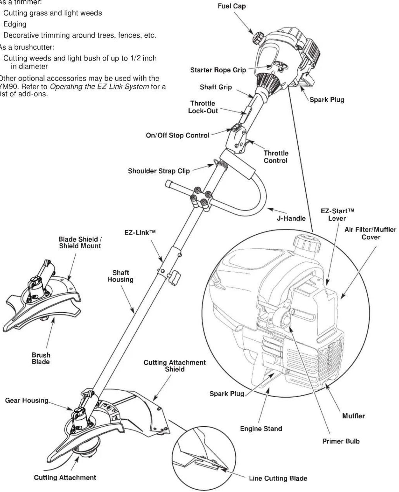
SECTION 2: KNOW YOUR UNIT
Applications
As a trimmer:
• Cutting grass and light weeds
- Edging
• Decorative trimming around trees, fences, etc.
As a brushcutter:
• Cutting weeds and light bush of up to 1/2 inch in diameter
Other optional accessories may be used with the YM90. Refer to Operating the EZ-Link System for a list of add-ons.
text_image
As a trimmer: Cutting grass and light weeds Edging Decorative trimming around trees, fences, etc. As a brushcutter: Cutting weeds and light bush of up to 1/2 inch in diameter Other optional accessories may be used with the YM90. Refer to Operating the EZ-Link System for a list of add-ons. Fuel Cap Starter Rope Grip Shaft Grip Throttle Lock-Out On/Off Stop Control Shoulder Strap Clip Spark Plug J-Handle EZ-Start™ Lever Air Filter/Muffler Cover Blade Shield / Shield Mount EZH Link™ Shaft Housing Brush Blade Cutting Attachment Shield Gear Housing Cutting Attachment Spark Plug Engine Stand Muffler Primer Bulb Line Cutting BladeSECTION 3: ASSEMBLY INSTRUCTIONS
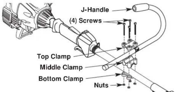
Installing and Adjusting the J-handle
- Place the J-handle between the top and middle clamp pieces. See Figure 1.
text_image
J-Handle (4) Screws Top Clamp Middle Clamp Bottom Clamp NutsFigure 1
- While holding the three pieces together, install the four (4) screws through the top clamp and into middle clamp.
NOTE: The holes in the top and middle clamp will line up only when assembled correctly. - Place the clamps and the J-handle over the shaft housing and onto the bottom clamp.
- Hold each hex nut in the bottom clamp recess with a finger. Start screws with a large Phillips screwdriver. Do not tighten until you make the handle adjustment.
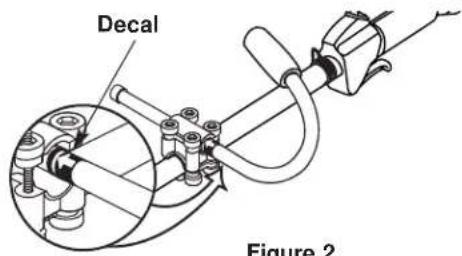
- Slide the J-handle in or out until the arrow/white line on the decal touches the clamp assembly. See Figure 2. You must first loosen the screws if the handle is pre-installed.
text_image
Decal Figure 2Figure 2
- While holding the unit in the operating position, arrange the J-handle to the location that provides you the best grip. See Figure 3.

natural_image
Line drawing of a person using a grass lawn power manual (no text or symbols)Figure 3
- Tighten the clamp screws evenly, until the J-handle is secure.
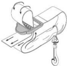
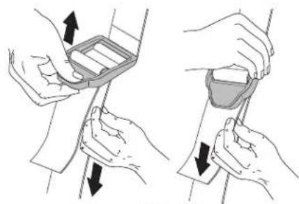
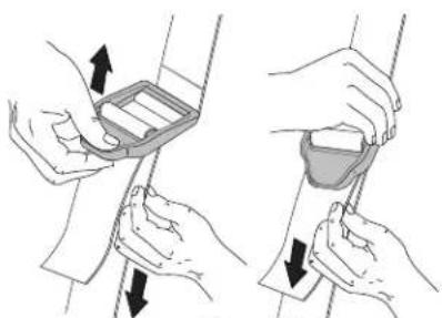
Install the Harness

WARNING: Always use the shoulder harness when using the cutting blade to avoid serious personal injury.
- Push the strap through the center of the buckle.
- Pull the strap over the cross bar and down through the slot in the buckle. See Figure 4.
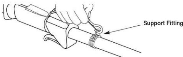
- Put the harness on over head and onto shoulder. Snap it on to the support fitting. See Figure 5.
- Adjust length to fit the operator's size. Pull tab to lengthen, pull strap to shorten. See Figure 6.
natural_image
Illustration of a mechanical device with rotating components and directional arrows (no text or symbols)Figure 4
text_image
Support FittingFigure 5
natural_image
Illustration of two hands holding a medical device with arrows indicating movement (no text or symbols)Figure 6
Remove and Install the Cutting Attachment Shield
Remove the cutting attachment shield when using the unit as a brushcutter

WARNING: The cutting attachment shield should NOT be installed when operating the unit with a blade. Remove the cutting attachment shield before removing or installing the blade.
Remove the cutting attachment shield from the shield mount by removing the three (3) screws with a flat blade screwdriver. See Figure 7. Store parts for future use.
SECTION 3: ASSEMBLY INSTRUCTIONS
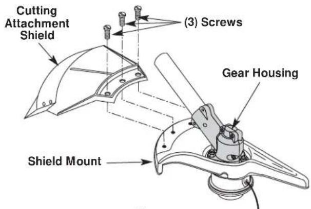
text_image
Cutting Attachment Shield (3) Screws Gear Housing Shield MountFigure 7
Install the cutting attachment shield when using the unit as a grass trimmer

WARNING: To avoid serious personal injury, the cutting attachment shield MUST be in place at all times while operating the unit as a grass trimmer.
Install the cutting attachment shield on the shield mount by inserting the three (3) screws into the shield mount. Tighten securely with a flat blade screwdriver. See Figure 7.
Remove the Cutting Attachment & Install the Cutting Blade
NOTE: To make cutting blade removal and installation easier, place the unit on the ground or on a work bench.
Remove the Cutting Attachment Shield
See Remove and Install the Cutting Attachment Shield.

WARNING: The gear housing gets hot with use. It can result in injury to the operator. The housing remains hot for a short time even after the unit is turned off. Do not touch the gear housing until it has cooled.
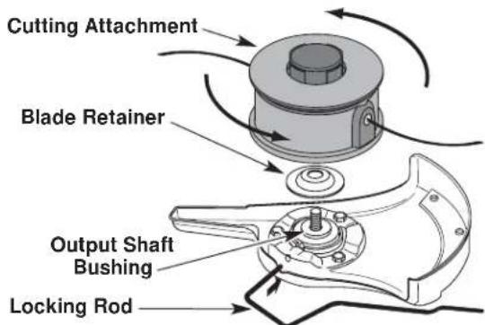
Remove the Cutting Attachment
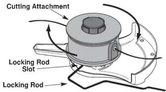
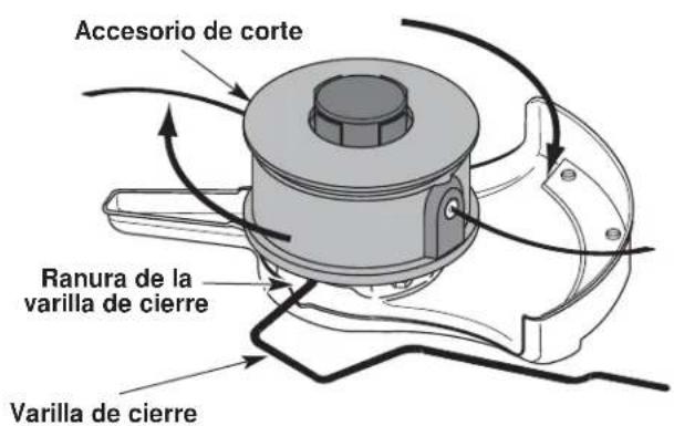
- Align the shaft bushing hole with the locking rod slot and insert the locking rod into the shaft bushing hole. See Figure 8.
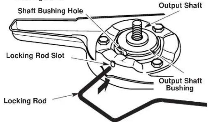
text_image
Shaft Bushing Hole Output Shaft Locking Rod Slot Output Shaft Bushing Locking RodFigure 8
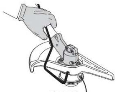
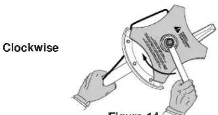
- Hold the locking rod in place by grasping it next to the boom of the unit. See Figure 9.
- While holding the locking rod, remove the cutting attachment by turning it clockwise off of the output shaft. See Figure 10. Store the cutting attachment for future use.
NOTE: The blade retainer under the cutting attachment will be used when installing the cutting blade.
natural_image
Illustration of a hand using a tool to lift a mechanical component (no text or symbols visible)Figure 9
text_image
Cutting Attachment Locking Rod Slot Locking RodFigure 10
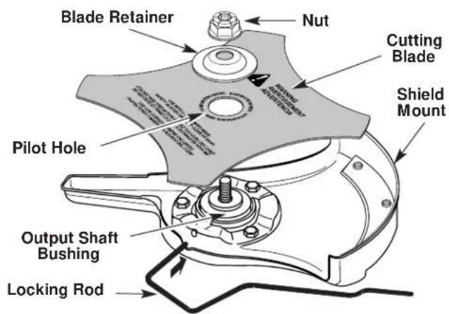
Install the Cutting Blade

WARNING: To avoid serious personal injury, always wear gloves while handling or installing the blade.
- Place the cutting blade on the output shaft bushing. See Figure 11.
text_image
Blade Retainer Nut Cutting Blade Shield Mount Pilot Hole Output Shaft Bushing Locking RodFigure 11
SECTION 3: ASSEMBLY INSTRUCTIONS
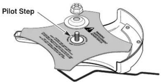
- Make sure that the cutting blade is centered on the pilot step and sitting flat against the output shaft bushing. See Figure 12.

WARNING: If the cutting blade is off-center, the unit will vibrate and the blade may fly off, causing possible serious personal injury.
text_image
Pilot Step 1.000mm x 2.000mm x 3.000mm x 4.000mm x 5.000mm x 6.000mm x 7.000mm x 8.000mm x 9.000mm x 10.000mm x 11.000mm x 12.000mm x 13.000mm x 14.000mm x 15.000mm x 16.000mm x 17.000mm x 18.000mm x 19.000mm x 20.000mm x 21.000mm x 22.000mm x 23.000mm x 24.000mm x 25.000mm x 26.000mm x 27.000mm x 28.000mm x 29.000mm x 30.000mm x 31.000mm x 32.000mm x 33.000mm x 34.000mm x 35.000mm x 36.000mm x 37.000mm x 38.000mm x 39.000mm x 40.000mm x 41.000mm x 42.000mm x 43.000mm x 44.000mm x 45.000mm x 46.000mm x 47.000mm x 48.000mm x 49.000mm x 50.000mm x 51.000mm x 52.000mm x 53.000mm x 54.000mm x 55.000mm x 56.000mm x 57.000mm x 58.000mm x 59.000mm x 60.000mm x 61.000mm x 62.000mm x 63.000mm x 64.000mm x 65.000mm x 66.000mm x 67.000mm x 68.000mm x 69.000mm x 70.000mm x 71.000mm x 72.000mm x 73.000mm x 74.000mm x 75.000mm x 76.000mm x 77.000mm x 78.000mm x 79.000mm x 80.00Figure 12
- Align the shaft bushing hole with the locking rod slot and insert the locking rod into the bushing hole. See Figure 8.
- Put the blade retainer and nut on the output shaft. Make sure that the blade is installed correctly.
-
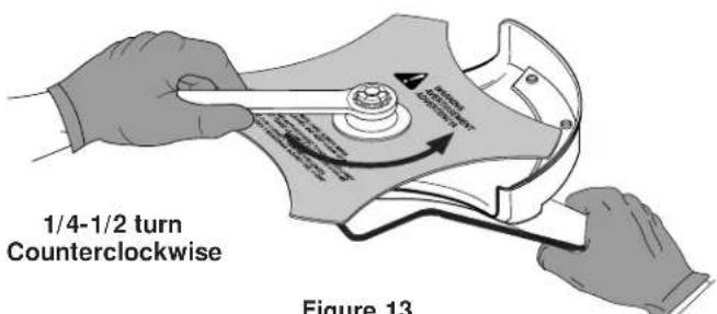
Tighten nut counterclockwise against the blade while holding the locking rod:
-
If using a torque wrench and an 5/8 inch socket tighten to: 325 - 335 in·lb, 27 - 28 ft.·lb, 37 - 38 N·m.
- Without a torque wrench, use a 5/8 inch closed-end or socket wrench, turning the nut until the blade retainer is snug against the shaft bushing. Make sure that the blade is installed correctly, then rotate the nut an additional 1/4 to 1/2 turn counterclockwise. See Figure 13.
text_image
1/4-1/2 turn Counterclockwise Figure 13Figure 13
- Remove the locking rod from the locking rod slot.

WARNING: To avoid serious personal injury or damage to the unit, do not start or operate this unit with the locking rod in the locking rod slot.

WARNING: Do not sharpen the cutting blade. Sharpening the blade can cause the blade tip to break off while in use. This can result in severe personal injury. Replace the blade.
Remove the Cutting Blade & Install the Cutting Attachment

WARNING: To avoid serious personal injury, always wear gloves while handling or installing the blade.
Remove the Cutting Blade
- Align the shaft bushing hole with the locking rod slot and insert the locking rod into the bushing hole. See Figure 8.
- Hold the locking rod in place by grasping it next to the boom of the unit. See Figure 14.
- While holding the locking rod, loosen the nut on the blade by turning it clockwise with a 5/8 inch closed-end or socket wrench. See Figure 14.
text_image
Clockwise Figure 14Figure 14
- Remove the nut, blade retainer and blade. Store the nut and blade together for future use in a secure place. Store out of children's reach.
Install the Cutting Attachment
- Align the shaft bushing hole with the locking rod slot and insert the locking rod into the shaft bushing hole. See Figure 8. Place the blade retainer on the output shaft with the flat surface against the output shaft bushing. See Figure 15. Screw the cutting attachment counterclockwise onto the output shaft. Tighten securely.
NOTE: The blade retainer must be installed on the output shaft in the position shown for the cutting attachment to work correctly.
text_image
Cutting Attachment Blade Retainer Output Shaft Bushing Locking RodFigure 15
- Remove the locking rod.
- Install the cutting attachment shield. Refer to Remove and Install the Cutting Attachment Shield.

WARNING: To avoid serious personal injury, the cutting head guard MUST be in place at all times while operating the unit as a trimmer.
SECTION 4: OIL AND FUEL INFORMATION
Oil and Fuel Mixing Instructions
Old and/or improperly mixed fuel is the main reason for improper unit performance. Be sure to use fresh, clean unleaded fuel. Follow the instructions carefully for the proper fuel/oil mixture.
Definition of Blended Fuels
Today's fuels are often a blend of gasoline and oxygenates such as ethanol, methanol, or MTBE (ether). Alcohol-blended fuel absorbs water. As little as 1% water in the fuel can make fuel and oil separate. It forms acids when stored. When using alcohol-blended fuel, use fresh fuel (less than 60 days old).
Using Blended Fuels
If you choose to use a blended fuel, or its use is unavoidable, follow recommended precautions:
• Always use fresh fuel mix per your operator's manual
• Always agitate the fuel mix before fueling the unit
- Drain the tank and run the engine dry before storing the unit
Using Fuel Additives
The bottle of 2-cycle oil that came with your unit contains a fuel additive which will help inhibit corrosion and minimize the formation of gum deposits. It is recommended that you use only our 2-cycle oil with this unit.
If unavailable, use a good 2-cycle oil designed for air-cooled engines along with a fuel additive, such as STA-BIL® Gas Stabilizer or an equivalent. Add 0.8 oz. (23 ml.) of fuel additive per gallon of fuel according to the instructions on the container. NEVER add fuel additives directly to the unit's fuel tank.

CAUTION: For proper engine operation and maximum reliability, pay strict attention to the oil and fuel mixing instructions on the 2-cycle oil container. Using improperly mixed fuel can severely damage the engine.
Thoroughly mix the proper ratio of 2-cycle engine oil with unleaded gasoline in a separate fuel can. Use a 40:1 fuel/oil ratio. Do not mix them directly in the engine fuel tank. See the table below for specific gas and oil mixing ratios.
NOTE: One gallon (3.8 liters) of unleaded gasoline mixed with one 3.2 oz. (95 ml.) bottle of 2-cycle oil makes a 40:1 fuel/oil ratio.

+

UNLEADED GAS 2-CYCLE OIL
1 US. GALLON + 3.2 FL. OZ. (3.8 LITERS) (95 ml)
1 LITER + 25 ml
MIXING RATIO - 40:1

WARNING: Gasoline is extremely flammable. Ignited vapors may explode. Always stop the engine and allow it to cool before filling the fuel tank. Do not smoke while filling the tank. Keep sparks and open flames at a distance from the area.

WARNING: Remove fuel cap slowly to avoid injury from fuel spray. Never operate the unit without the fuel cap securely in place.

WARNING: Add fuel in a clean, well-ventilated outdoor area. Wipe up any spilled fuel immediately. Avoid creating a source of ignition for spilled fuel. Do not start the engine until fuel vapors dissipate.
NOTE: Dispose of the old fuel/oil mix in accordance to Federal, State and Local regulations.
SECTION 5: STARTING/STOPPING INSTRUCTIONS

WARNING: Operate this unit only in a well-ventilated outdoor area. Carbon monoxide exhaust fumes can be lethal in a confined area.

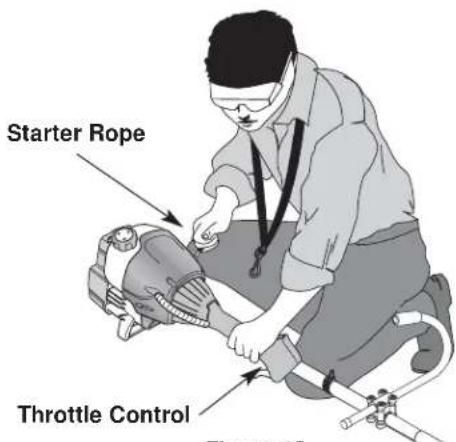
WARNING: Avoid accidental starting. Make sure you are in the starting position when pulling the starter rope. See Figure 18. To avoid serious injury, the operator and unit must be in a stable position while starting.
To avoid serious personal injury, ensure any Add-On being used is installed correctly and secure before starting unit.
Starting Instructions
IF... You are starting a warm engine, begin at step 4.
-
Mix gas with oil. Fill fuel tank with fuel/oil mixture. See Oil and Fuel Mixing Instructions.
-
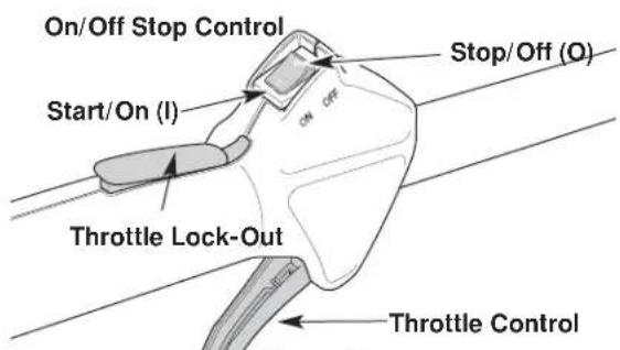
Make sure the On/Off Stop Control is in the ON (I) position. See Figure 16.
-
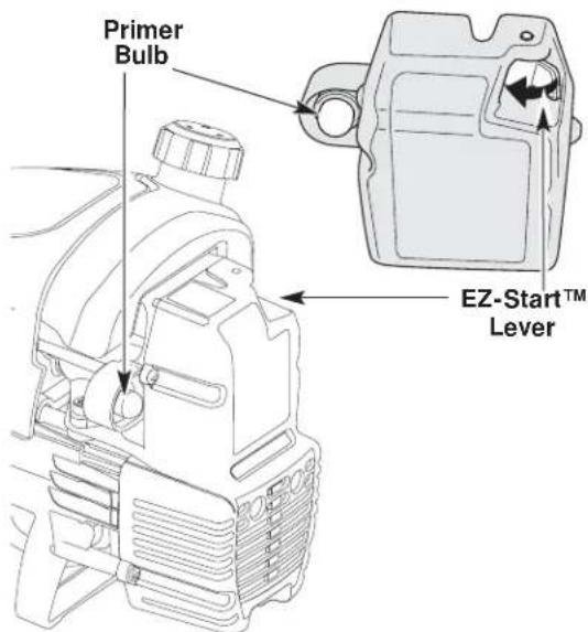
Fully press and release the primer bulb 10 times, slowly, until FUEL IS VISIBLE IN THE PRIMER BULB. See Figure 17. If you can't see fuel in the bulb, press and release the bulb as many times as it takes before you can see fuel in it.
-
Push the EZ-Start™ Lever to the left until it clicks and locks into place. See Figure 17.
-
With the unit in the starting position, DO NOT SQUEEZE THE THROTTLE CONTROL. See Figure 18. Pull the starter rope 5 times briskly, making sure the EZ-Start™ lever is pushed to the left.
IF... The engine does not start, go back to step 3.
IF... The engine starts to run before the fifth pull, go to step 6.
IF... The outside temperature or engine temperature exceeds 90^ F and the engine fails to start after 5 pulls, fully squeeze the throttle control and pull the starter rope briskly 3 to 8 more times. The engine should start within these pulls.
NOTE: When starting, the EZ-Start™ Lever will automatically click off when you squeeze the throttle control.
- When the engine starts, squeeze the throttle control to warm up the engine for 5 to 10 seconds. The EZ-Start™ Lever will click off automatically. See Figure 17.
IF... The engine stalls while squeezing the throttle, go back to step 4.
IF... The engine stalls before you squeeze the throttle control, hold the throttle control and pull the starter rope until the trimmer starts.
text_image
On/Off Stop Control Start/On (I) Stop/Off (O) Throttle Lock-Out Throttle ControlFigure 16
text_image
Primer Bulb EZ-Start™ LeverFigure 17
text_image
Starter Rope Throttle Control Figure 10Figure 18
Stopping Instructions
-
Release your hand from the throttle control. See Figure 18. Allow the engine to cool down by idling.
-
Push and hold the On/Off Stop Control in the OFF (O) position until the engine stops running. See Figure 16
SECTION 6: OPERATING INSTRUCTIONS
Operating the EZ-Link™ System
The EZ-Link™ system enables the use of these optional Add-Ons:
Blower/Vacuum . . . . . . . . . . . . . . . . . . . . . . . . . . . . . . . . . . . . . . . . . . . . . . . . . . . . . . . . . BV720r
Cultivator GC720r
Edger LE720r
Hedge Trimmer.... HS720r
Snow Thrower .... ST720r
Straight Shaft Trimmer .... SS725r
Tree Pruner TP720r
Turbo Blower TB720r

WARNING: Read and understand the operator's manual for each add-on prior to operation.
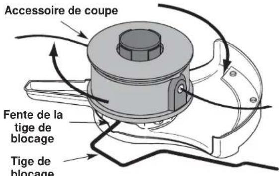
Removing the Cutting Attachment or Add-Ons
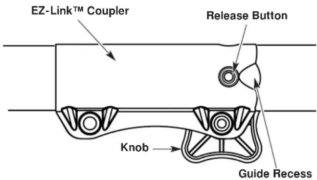
- Turn the knob counterclockwise to loosen. See Figure 19.
- Press and hold the release button. See Figure 19.
- While firmly holding the upper shaft housing, pull the cutting attachment or add-on straight out of the EZ-Link™ coupler. See Figure 20.
Installing the Cutting Attachment or Add-On

WARNING: To avoid serious personal injury and damage to the unit, shut off the unit before removing or installing add-ons.
NOTE: Place the unit on the ground or on a work bench to make add-on installation or removal easier.
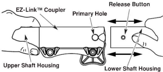
1. Turn knob counterclockwise to loosen.
text_image
EZ-Link™ Coupler Release Button Knob Guide RecessFigure 19
- While firmly holding the add-on, push it straight into the EZ-Link™ coupler. See Figure 20.
NOTE: Aligning the release button with the guide recess will help installation. See Figure 19.
text_image
EZ-Link™ Coupler Primary Hole Release Button Upper Shaft Housing Lower Shaft HousingFigure 20
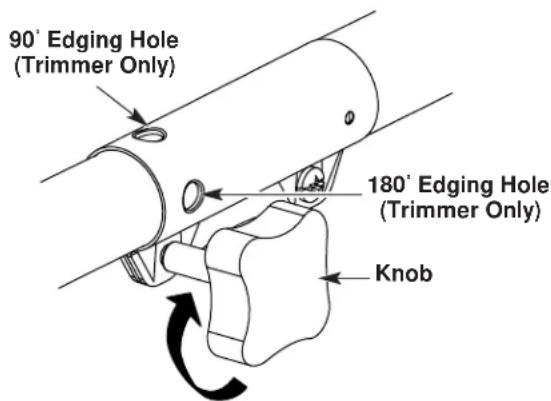
- Turn the knob clockwise to tighten. See Figure 21.

CAUTION: Lock the release button in the primary hole and securely tighten the knob before operating this unit
text_image
90° Edging Hole (Trimmer Only) 180° Edging Hole (Trimmer Only) KnobFigure 21

CAUTION: The cutting attachment and add-ons with the EZ-Link™ system are to be used in the primary hole unless stated otherwise in the specific add-ons operator's manual. Using the wrong hole could lead to personal injury or damage to the unit.
For edging (when using the line head cutting attachment with EZ-Link™ models), lock the release button of the cutting attachment into the 90° edging hole or the 180° edging hole. See Figure 21.
SECTION 6: OPERATING INSTRUCTIONS
Holding the Trimmer

WARNING: Always wear eye, hearing, foot and body protection to reduce the risk of injury when operating this unit.
Before operating the unit, stand in the operating position. See Figure 22. Check for the following:
- The operator is wearing eye protection and proper clothing
- With a slightly-bent right arm, the operator's right hand is holding the shaft grip
- The operator's left arm is straight, the left hand holding the J-handle
• The unit is at waist level - The cutting attachment is parallel to the ground and easily contacts the grass without the need to bend over
Once you are in the operating position, hook the shoulder strap to the unit.

natural_image
Line drawing of a person using a manual lawn power presser on grass (no text or symbols)Figure 22
Adjusting Trimming Line Length
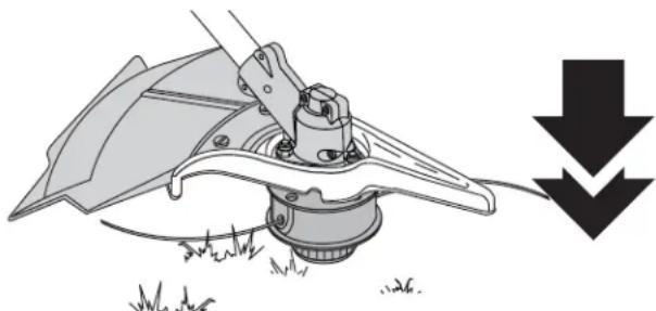
The Bump Head ^™ cutting attachment allows you to release trimming line without stopping the engine. To release more line, lightly tap the cutting attachment on the ground while operating the trimmer at high speed. See Figure 23.
NOTE: Always keep the trimming line fully extended. Line release becomes more difficult when the cutting line gets shorter.
natural_image
Mechanical diagram showing a tool interacting with a mechanical component, with a downward arrow indicating compression or disassembly (no text or symbols present)Figure 23
Each time the head is bumped, about 1 inch (25.4 mm) of trimming line releases. A blade in the cutting attachment shield will cut the line to the proper length if any excess line is released.
For best results, tap the bump knob on bare ground or hard soil. If you attempt a line release in tall grass, the engine may stall. Always keep the trimming line fully extended. Line release becomes more difficult when the cutting line gets shorter.
NOTE: Do not rest the bump knob on the ground while the unit is running.

CAUTION: Do not remove or alter the line cutting blade assembly. Excessive line length may make the unit overheat.
Some line breakage will occur from:
• Entanglement with foreign matter
- Normal line fatigue
- An attempt to cut thick, stalky weeds
- Forcing the line into objects such as walls or fence posts
Tips for Best Trimming Results
- For best trimming results, operate unit at full throttle.
- Keep the cutting attachment parallel to the ground.
- Do not force the cutting attachment. Allow the tip of the line to do the cutting, especially along walls. Cutting with more than the tip will reduce cutting efficiency and may overload the engine.
- Cut grass over 8 inches (200 mm) tall by working from top to bottom in small increments to avoid premature line wear or engine drag.
- Cut from left to right whenever possible. Cutting to the right improves the unit's cutting efficiency. Clippings are thrown away from the operator.
- Slowly move the trimmer into and out of the cutting area at the desired height. Move either in a forward-to-backward or side-to-side motion. Cutting shorter lengths produces the best results.
- Trim only when grass and weeds are dry.
- The life of your cutting line is dependent upon:
• Following the trimming techniques
• What vegetation is being cut
- Where vegetation is cut
For example, the line will wear faster when trimming against a foundation wall as opposed to trimming around a tree.
SECTION 6: OPERATING INSTRUCTIONS
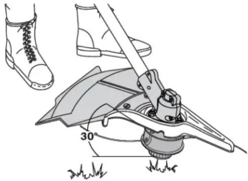
Decorative Trimming
Decorative trimming refers to the removal of vegetation around trees, posts, fences and more.
Rotate the whole unit so that the cutting attachment is at a 30^ angle to the ground. See Figure 24.
text_image
30°Figure 24
Using the Cutting Blade

WARNING: Always wear eye, hearing, foot, body protection and the shoulder strap to reduce the risk of injury when operating this unit.

WARNING: Do not use the cutting blade for edging or as an edger. Severe personal injury to yourself or others can result.
Before operating the unit with the cutting blade, stand in the operating position. See Figure 25. Refer to Holding the Trimmer.
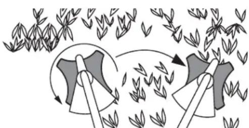
Cutting Blade Operating Tips
To establish a rhythmic cutting procedure:
- Plant feet firmly, comfortably apart.
- Bring the engine to full throttle before entering the material to be cut. At full throttle the blade has maximum cutting power and is less likely to bind, stall or cause blade thrust (which can result in serious personal injury to the operator or others).

WARNING: Blade thrust may occur when the spinning blade contacts an object that it does not immediately cut. Blade thrust can be violent enough to cause the unit and/or operator to be propelled in any direction, and possibly lose control of the unit. Blade thrust can occur without warning if the blade snags, stalls or binds. This is more likely to occur in areas where it is difficult to see the material being cut.
- Cut while swinging the upper part of your body from left to right.
- Always release the throttle trigger and allow the engine to return to idle speed when not cutting.
- When you are finished, always unsnap the unit from the harness before taking off the harness.

WARNING: The blade continues to spin after the engine is turned off. The coasting blade can seriously cut you if accidentally touched.
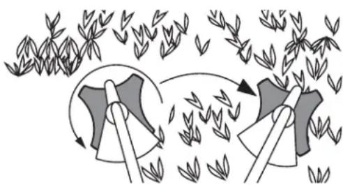
- Swing the unit in the opposite direction as the blade spins, which increases the cutting action.
- After the return swing, move forward to the next area to be cut plant your feet again.
- The cutting blade is designed with a second cutting edge. You can use it by removing the blade, turning it upside down, and reinstalling it.

WARNING: Do not sharpen the cutting blade. Sharpening the blade can cause the blade tip to break off while in use. This can result in severe personal injury to yourself or others. Replace the blade.
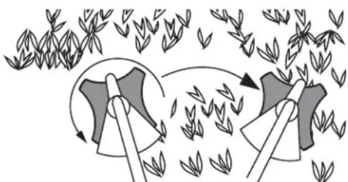
To reduce the chance of material wrapping around the blade, follow these steps:
- Cut at full throttle
- Swing the unit into material to be cut from your left to your right, see Figure 26
- Avoid the material just cut as you make the return swing

WARNING: Do not clear away any cut material with the engine running or blade turning. To avoid serious personal injury, turn off the engine. Allow the blade to stop before removing materials wrapped around the blade shaft.

natural_image
Line drawing of a person spraying a manual outdoors with plants in the background (no text or symbols)Figure 25
natural_image
Illustration of two hands operating a blade with arrows indicating motion, surrounded by scattered leaves (no text or symbols)Figure 26
SECTION 7: MAINTENANCE AND REPAIR INSTRUCTIONS
Maintenance Schedule
Perform these required maintenance procedures at the frequency stated in the table. These procedures should also be a part of any seasonal tune-up.
NOTE: Some maintenance procedures may require special tools or skills. If you are unsure about these procedures take your unit to any non-road engine repair establishment, individual or authorized service dealer.

WARNING: To prevent serious injury, never perform maintenance or repairs with unit running. Always service and repair a cool unit. Disconnect the spark plug wire to ensure that the unit cannot start.
NOTE: Maintenance, replacement, or repair of the emission control devices and system may be performed by any non-road engine repair establishment, individual or authorized service dealer.
In order to assure peak performance of your engine, inspection of the engine exhaust port may be necessary after 50 hours of operation. If you notice lost RPM, poor performance or general lack of acceleration, this service may be required. If you feel your engine is in need of this inspection, refer service to any non-road engine repair establishment, individual or authorized service dealer for repair. DO NOT attempt to perform this process yourself as engine damage may result from contaminants involved in the cleaning process for the port.
| FREQUENCY MAINTENANCE | REQUIRED REFER TO | |
| Before starting engine Fill fuel tank with fresh fuel Page 11 | ||
| Every 10 hours Clean and re-oil air filter Page 18 | ||
| Every 25 hours | Check and clean spark arrestorCheck spark plug condition and gap | Page 19Page 20 |
| Every 50 hours | Inspect exhaust port and spark arrestor screen for clogging or obstruction to assure maximum performance levels | Page 19 |
Line Installation
This section covers both SplitLine ^™ and standard single line installation.
Always use Genuine Factory Parts ^™ 0.095 in. (2.41 mm) replacement line. Using line other than the specified may make the engine overheat or fail.

WARNING: Never use metal-reinforced line, wire, chain or rope. These can break off and become dangerous projectiles.
There are two methods to replace the trimming line:
• Wind the inner reel with new line
• Install a prewound inner reel
Winding the Existing Inner Reel
- Hold the outer spool with one hand and unscrew the bump knob counterclockwise. See Figure 27. Inspect the bolt inside the bump knob to make sure it moves freely. Replace the bump knob if damaged.
- Remove the inner reel from the outer spool. See Figure 27.
- Remove spring from the inner reel. See Figure 27.
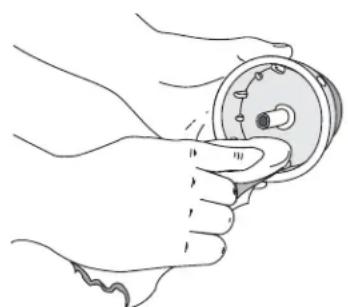
- Use a clean cloth to wipe the inner reel, spring, shaft, and inner surface of the outer spool. See Figure 28.
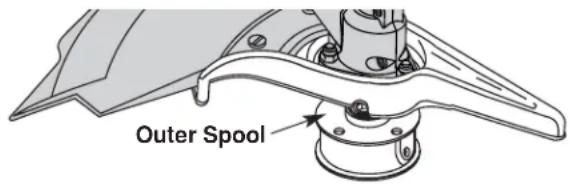
text_image
Outer Spool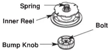
text_image
Spring Inner Reel Bolt Bump KnobFigure 27
natural_image
Line drawing of a hand holding a circular mechanical component (no text or symbols)Figure 28
SECTION 7: MAINTENANCE AND REPAIR INSTRUCTIONS
- Check the indexing teeth on the inner reel and outer spool for wear. If necessary, remove burrs or replace the reel and spool. See Figure 29.
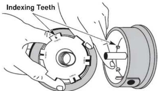
text_image
Indexing TeethFigure 29
NOTE: SplitLine™ can only be used with the inner reel containing slotted holes. Single line can be used on either type of inner reel. Use Figure 30 to identify the inner reel you have.
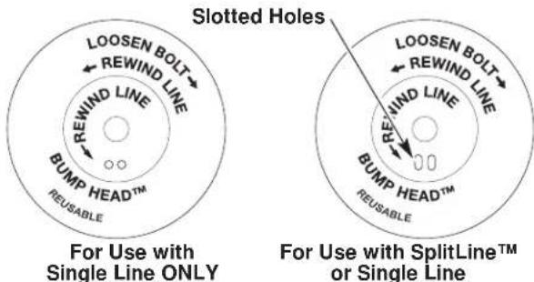
text_image
Slotted Holes For Use with Single Line ONLY For Use with SplitLine™ or Single LineFigure 30
NOTE: Always use the correct line length when installing trimming line on the unit. The line may not release properly if the line is too long.
Single Line Installation
Go To Step 8 for SplitLine™ Installation
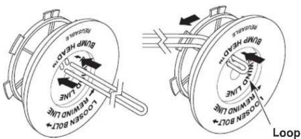
- Cut approximately 25 feet (7.6 m) of new trimming line, then loop it into two equal lengths. Insert each end of the line through one of the two holes in the inner reel. Pull the line through the inner reel so that the loop is as small as possible. See Figure 31.
text_image
Retroxide Bump Head" 1.0 2.0 3.0 4.0 5.0 6.0 7.0 8.0 9.0 10.0 11.0 12.0 13.0 14.0 15.0 16.0 17.0 18.0 19.0 20.0 21.0 22.0 23.0 24.0 25.0 26.0 27.0 28.0 29.0 30.0 31.0 32.0 33.0 34.0 35.0 36.0 37.0 38.0 39.0 40.0 41.0 42.0 43.0 44.0 45.0 46.0 47.0 48.0 49.0 50.0 51.0 52.0 53.0 54.0 55.0 56.0 57.0 58.0 59.0 60.0 61.0 62.0 63.0 64.0 65.0 66.0 67.0 68.0 69.0 70.0 71.0 72.0 73.0 74.0 75.0 76.0 77.0 78.0 79.0 80.0 81.0 82.0 83.0 84.0 85.0 86.0 87.0 88.0 89.0 90.0 91.0 92.0 93.0 94.0 95.0 96.0 97.0 98.0 99.0 100.0Figure 31
- Wind the lines in tight even layers onto the reel. See Figure 32. Wind the line in the direction indicated on the inner reel. Place your index finger between the two lines to stop the lines from overlapping. Do not overlap the ends of the line. Proceed to step 11.

text_image
LOOSEN BOLT REWIND REWIND LINE BUMP HEAD™ REWABLEFigure 32
SplitLine™ Installation
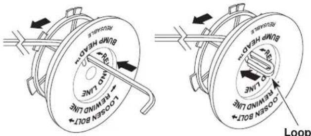
- Cut approximately 12 feet (3.65 m) of new trimming line. Insert one end of the line through one of the two holes in the inner reel. Pull the line through the inner reel until only about 4 inches is left out. See Figure 33.
- Insert the end of the line into the open hole in the inner reel and pull the line tight to make the loop as small as possible. See Figure 33.
text_image
Bump HFD1 No line Open Bolt Bump HFD2 Open Bolt LoopFigure 33
- Before winding, split the line back about 6 inches.
- Wind the line in tight even layers in the direction indicated on the inner reel.
NOTE: Failure to wind the line in the direction indicated will cause the cutting attachment to operate incorrectly.
- Insert the ends of the line into the two holding slots. See Figure 34.
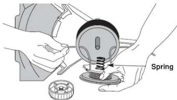
- Insert the ends of the line through the eyelets in the outer spool and place inner reel with spring inside the outer spool. See Figure 35. Push the inner reel and outer spool together. While holding the inner reel and outer spool, grasp the ends and pull firmly to release the line from the holding slots in the reel.
SECTION 7: MAINTENANCE AND REPAIR INSTRUCTIONS
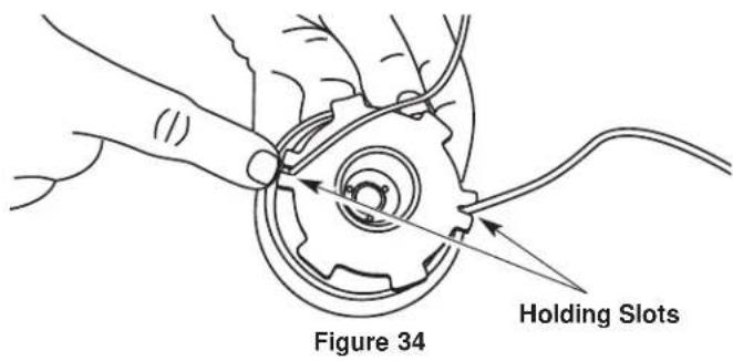
text_image
Figure 34 Holding SlotsNOTE: The spring must be assembled on the inner reel before reassembling the cutting attachment.
- Hold the inner reel in place and install the bump knob by turning counterclockwise. Tighten securely.
text_image
SpringFigure 35
Installing a Pre Wound Reel
- Hold the outer spool with one hand and unscrew the bump knob clockwise. See Figure 27. Inspect the bolt inside the bump knob to make sure it moves freely. Replace the bump knob if damaged.
- Remove the old inner reel from the outer spool. See Figure 27.
- Remove the spring from the old inner reel. See Figure 27.
- Place the spring in the new inner reel.
NOTE: The spring must be assembled on the inner reel before reassembling the cutting attachment.
- Insert the ends of the line through the eyelets in the outer spool. See Figure 35.
- Place the new inner reel inside the outer spool. Push the inner reel and outer spool together. While holding the inner reel and outer spool, grasp the ends and pull firmly to release the line from the holding slots in the reel.
- Hold the inner reel in place and install the bump knob by turning counterclockwise. Tighten securely.
Replacement Parts
For replacement parts, refer to the Accessories / Replacement Parts section.
Air Filter Maintenance
Removing the Air Filter/Muffler Cover

WARNING: To avoid serious personal injury, always turn your trimmer off and allow it to cool before you clean or service it.
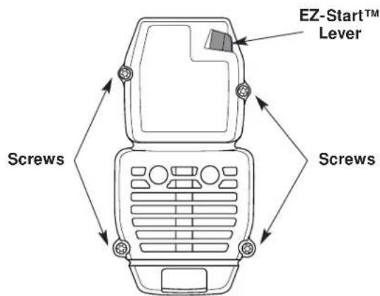
- Remove the four (4) screws securing the air filter/muffler cover. See Figure 36. Use a flat blade or T20 Torx bit screwdriver.
- Pull the cover from the engine. Do not force.
text_image
EZ-Start™ Lever Screws ScrewsFigure 36
Cleaning the Air Filter

WARNING: To avoid serious personal injury, always turn your trimmer off and allow it to cool before you clean it or perform any maintenance.
Clean and re-oil the air filter every 10 hours of operation. It is an important item to maintain. Failure to maintain the air filter will VOID the warranty.
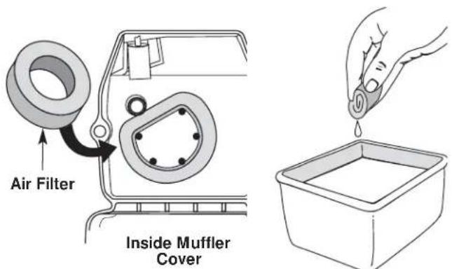
- Remove air filter/muffler cover. See Removing the Air Filter/Muffler Cover.
- Turn cover over and look inside to locate the air filter. Remove the air filter from inside the air filter/muffler cover. See Figure 37.
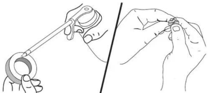
- Wash the filter in detergent and water. See Figure 38. Rinse the filter thoroughly. Squeeze out excess water. Allow it to dry completely.
- Apply enough clean SAE 30 oil to lightly coat the filter. See Figure 39.
- Squeeze the filter to spread and remove excess oil. See Figure 40.
SECTION 7: MAINTENANCE AND REPAIR INSTRUCTIONS
text_image
Air Filter Inside Muffler CoverFigure 38 Figure 37
natural_image
Illustration of two hands holding a ring-shaped object, one being adjusted for size (no text or symbols)Figure 39
Figure 40
- Replace the air filter inside the air filter/muffler cover. See Figure 37.
NOTE: Operating the unit without the air filter and air filter/muffler cover assembly, will VOID the warranty.
Reinstalling the Air Filter/Muffler Cover
- Place the air filter/muffler cover over the back of the carburetor and muffler. Align the screw holes.
- Insert the four (4) screws into the holes in the air filter/muffler cover and tighten. See Figure 36. Do not over tighten.
Spark Arrestor Maintenance
- Remove air filter/muffler cover. See Removing the Air Filter/Muffler Cover.
- Locate muffler front and the two (2) bolts securing it to the engine. See Figure 41. Remove the two (2) bolts using a flatblade screwdriver or 5/16-inch socket or nut driver. Pull muffler off of the engine.
- Turn muffler over to the back side and locate the exhaust gasket. Remove the muffler gasket from the muffler. See Figure 41.
NOTE: If the exhaust gasket is torn or damaged, replace it with a new gasket before reassembling muffler.
-
Using a small flatblade screwdriver, carefully pry up the spark arrestor from the recessed hole. See Figure 42. Remove the spark arrestor from the muffler.
-
Clean the spark arrestor with a wire brush. Replace it if it is damaged or if it is impossible to clean thoroughly. See Figure 42.
- Reinstall the spark arrestor by pressing it into the recessed hole on the muffler's back side. Make sure it fits tightly against the muffler and is not raised up.
- Place the exhaust gasket against muffler's back side. Align the gasket bolt holes with the bolt holes in the muffler. While holding exhaust gasket in place, insert the bolts into the muffler's front side. See Figure 41.
- Place the muffler (with the exhaust gasket in place and bolts inserted), against the engine, aligning the bolt holes. Tighten the bolts to secure the muffler to the engine. If using a torque wrench torque to: 80-90 in.·lb. (9-10.2 N·m).

WARNING: If the muffler is not tightened securely, it could fall off causing damage to the unit and possible serious personal injury.
- Reinstall the air filter/muffler cover.
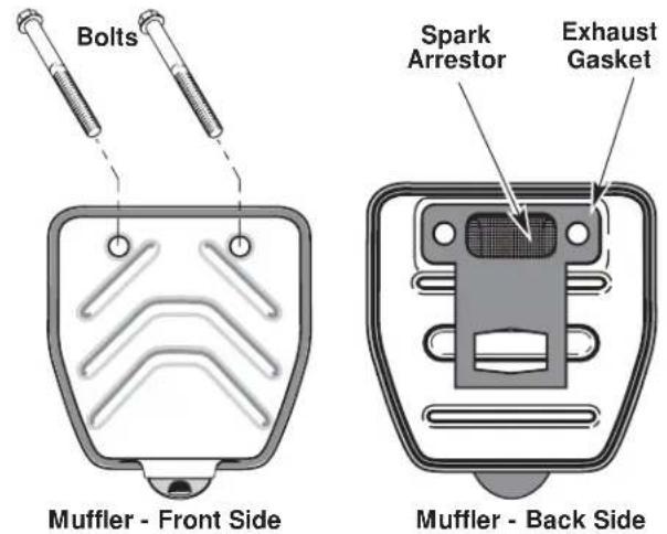
Figure 41

text_image
Spark Arrestor Flat blade Screwdriver Spark ArrestorMuffler - Back Side
Figure 42
SECTION 7: MAINTENANCE AND REPAIR INSTRUCTIONS
Carburetor Adjustment
The idle speed of the engine is adjustable through the air filter/muffler cover. See Figure 43.
NOTE: Careless adjustments can seriously damage your unit. An authorized service dealer should make carburetor adjustments.
Check Fuel Mixture
Old and/or improperly mixed fuel is usually the reason for improper unit performance. Drain and refill the tank with fresh, properly mixed fuel prior to making any adjustments. Refer to Oil and Fuel Information.
Clean Air Filter
The condition of the air filter is important to the operation of the unit. A dirty air filter will restrict air flow and change the air/fuel mixture. This is often mistaken for an out of adjustment carburetor. Check the condition of the air filter before adjusting the idle speed screw. Refer to Air Filter Maintenance.
Adjust Idle Speed

WARNING: The cutting attachment may spin during idle speed adjustments. Wear protective clothing and observe all safety instructions to prevent serious personal injury.
If, after checking the fuel mixture and cleaning the air filter, the engine still will not idle, adjust the idle speed as follows.
- Start the engine and let it run at a high idle for a minute to warm up. See Starting/Stopping Instructions.
- Release the throttle trigger and let the engine idle. If the engine stops, insert a small Phillips or flat blade screwdriver into the hole in the air filter/muffler cover. See Figure 43. Turn the idle speed screw in, clockwise, 1/8 of a turn at a time (as needed) until the engine idles smoothly.
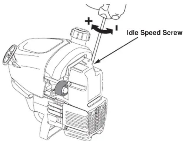
text_image
Idle Speed ScrewFigure 43
NOTE: The cutting attachment should not rotate when the engine idles.
- If the cutting attachment rotates when the engine idles, turn the idle speed screw counterclockwise 1/8 of a turn at a time (as needed), to reduce idle speed.
Checking the fuel mixture, cleaning the air filter, and adjusting the idle speed should solve most engine problems.
If this is not the case and the following are all true:
- The engine will not idle
- The engine hesitates or stalls on acceleration
• There is a loss of engine power
Have the carburetor adjusted by an authorized service dealer.

WARNING: After turning the unit off, make sure the cutting attachment has stopped before setting the unit down. This helps prevent serious personal injury.
Replacing the Spark Plug
Use a Champion RDJ7Y spark plug (or equivalent). The correct air gap is 0.020 inch (0.5 mm). Remove the plug after every 25 hours of operation and check its condition.
- Stop the engine and allow it to cool. Grasp the plug wire firmly and pull it from the spark plug.
- Clean around the spark plug. Remove the spark plug from the cylinder head by turning a 5/8 in. socket counterclockwise.
- Replace cracked, fouled or dirty spark plug. Set the air gap at 0.020 in. (0.5 mm) using a feeler gauge. See Figure 44.

CAUTION: Do not sand blast, scrape or clean electrodes. Grit in the engine could damage the cylinder.
- Install a correctly-gapped spark plug in the cylinder head. Tighten by turning the 5/8 inch socket clockwise until snug.
If using a torque wrench torque to:
110-120 in.·lb. (12.3-13.5 N·m).
Do not over tighten.

text_image
0.020 in. (0.5 mm)Figure 44
SECTION 7: MAINTENANCE AND REPAIR INSTRUCTIONS
Cleaning

WARNING: To avoid serious personal injury, always turn your trimmer off and allow it to cool before you clean or service it.
Use a small brush to clean off the outside of the unit. Do not use strong detergents. Household cleaners that contain aromatic oils such as pine and lemon, and solvents such as kerosene, can damage plastic housing or handle. Wipe off any moisture with a soft cloth.
Storage
- Never store the unit with fuel in the tank where fumes may reach an open flame or spark.
- Allow the engine to cool before storing.
- Store the unit locked up to prevent unauthorized use or damage.
- Store the unit in a dry, well-ventilated area.
- Store the unit out of the reach of children.
Long Term Storage
If the unit will be stored for an extended time, use the following storage procedure:
- Drain all fuel from the fuel tank into a container with the same 2-cycle fuel mixture. Do not use fuel that has been stored for more than 60 days. Dispose of the old fuel/oil mix in accordance to Federal, State, and Local regulations.
- Start the engine and allow it to run until it stalls. This ensures that all fuel has been drained from the carburetor.
- Allow the engine to cool. Remove the spark plug and put 1 oz. (30 ml) of any high quality motor oil or 2-cycle oil into the cylinder. Pull the starter rope slowly to distribute the oil. Reinstall the spark plug.
NOTE: Remove the spark plug and drain all of the oil from the cylinder before attempting to start the trimmer after storage.
- Thoroughly clean the unit and inspect for any loose or damaged parts. Repair or replace damaged parts and tighten loose screws, nuts or bolts. The unit is ready for storage.
Transporting
- Allow the engine to cool before transporting.
- Secure the unit while transporting.
- Drain fuel from unit.
- Tighten fuel cap before transporting.
Accessories/Replacement Parts
2-Cycle Oil 147543
Spark Plug 610311
Spark Arrestor 182747
Replacement Line 180120
Replacement Line Cartridge 147345
Inner Reel Spring 610636
Outer Spool 683301
Inner Reel 147495
Bump Knob 180814
Fuel Cap 180000
Shoulder Strap 682075
For specific replacement parts, refer to the parts list located on the inside back cover of this manual.
SECTION 8: TROUBLESHOOTING GUIDE
| Trouble | Possible Cause(s) | Corrective Action |
| ENGINE WILL NOT START | Empty fuel tankPrimer bulb wasn't pressed enoughEngine is floodedOld or improperly mixed fuelFouled spark plugPlugged spark arrestorEZ-Start lever was not set | Fill fuel tank with properly-mixed fuelPress primer bulb fully and slowly 10 timesHold throttle control and pull starter rope until it startsDrain gas tank and add fresh fuel mixtureReplace or clean spark plugClean or replace the spark arrestorMove lever to start |
| ENGINE WILL NOT IDLE | Air filter is pluggedOld or improperly mixed fuelImproper carburetor adjustment | Replace or clean the air filterDrain gas tank and add fresh fuel mixtureAdjust according to the Carburetor Adjustment section |
| ENGINE WILL NOT ACCELERATE | Old or improperly mixed fuelImproper carburetor adjustmentCutting attachment bound with grassDirty air filterPlugged spark arrestor | Drain gas tank and add fresh fuel mixtureTake to an authorized service dealer for adjustmentStop the engine and clean the cutting attachmentClean or replace the air filterClean or replace spark arrestor |
| ENGINE LACKS POWER OR STALLS WHEN CUTTING | Old or improperly mixed fuelImproper carburetor adjustmentFouled spark plugPlugged spark arrestor | Drain gas tank and add fresh fuel mixtureTake to an authorized service dealer for adjustmentReplace or clean spark plugClean or replace the spark arrestor |
| CUTTING ATTACHMENT WILL NOT ADVANCE LINE | Cutting attachment bound with grassCutting attachment out of lineInner reel bound upCutting head is dirtyLine weldedLine twisted when refilledNot enough line is exposed | Stop the engine and clean cutting attachmentRefill with new lineReplace the inner reelClean inner reel and outer spoolDisassemble, remove the welded section and rewindDisassemble and rewind the linePush the bump knob and pull out line until 4 inches (102 mm) of line is outside of the cutting attachment |
| CUTTING LINE ADVANCES WILDLY | Oil is in the cutting headClean the cutting head attachment | |
If further assistance is required, contact your authorized service dealer
SECTION 9: SPECIFICATIONS
Engine\*
Engine Type.... Air-Cooled, 2-Cycle
Stroke 1.25 in. (31.75 mm)
Displacement 1.9 cu in. (31 cc)
Clutch Type Centrifugal
Idle Speed RPM 2,800 - 4,400 rpm
Operating RPM 7,200+ rpm
Ignition Type...... Electronic
Ignition Switch...... Rocker Switch
Spark Plug Gap 0.020 in. (0.5 mm)
Lubrication.... Fuel/Oil Mixture
Fuel/Oil Ratio 40:1
Carburetor Diaphragm, All-Position
Starter.... Auto Rewind
Muffler ....Baffled with Guard
Throttle Manual Spring Return
Fuel Tank Capacity 13 oz. (384 ml)
Drive Shaft and Cutting Attachment\*
Drive Shaft Housing ...... Steel Tube, EZ-Link™
Throttle Control.... Finger-Tip Trigger with Lock-Out
Approximate Unit Weight (No fuel, with cutting attachment, shield and J-handle).... 14 lbs. (6.35 kg)
Cutting Mechanism 4-Tooth Cutting Blade, Dual String Cutting Head
Line Spool...... Bump Line Releaser
Line Spool Diameter 4 inches (101.6 mm)
Trimming Line Diameter 0.095 inch (2.41 mm)
Cutting Path Diameter, Cutting Attachment 18 inches (45.7 cm)
Cutting Path Diameter, Cutting Blade 8 inches (204 mm)
Shoulder Harness Single Quick-Snap
*All specifications are based on the latest product information available at the time of printing. We reserve the right to make changes at any time without notice.
SECTION 9: NOTES
EPA Emission Control Warranty Statement
Your Warranty Rights and Obligations
The Environmental Protection Agency and MTD LLC (MTD) are pleased to explain the emission control system warranty on your 2002 and later small off-road engine. New small off-road engines must be designed, built and equipped to meet stringent anti-smog standards. Yard Man must warrant the emission control system on your small off-road engine for the periods of time listed below provided there has been no abuse, neglect or improper maintenance of your small off-road engine.
Your emission control system may include parts such as the carburetor or fuel-injected system, the ignition system, and catalytic converter. Also included may be hoses, belts, connectors and other emission-related assemblies.
Where a warrantable condition exists, Yard Man will repair your small off-road engine at no cost to you including diagnosis, parts and labor.
The 2002 and later small off-road engines are warranted for two years. If any emission-related part on your engine is defective, the part will be repaired or replaced my Yard Man.
Owners Warranty Responsibilities
- As the small off-road engine owner, you are responsible for the performance of the required maintenance listed in your operator's manual. Yard Man recommends that you retain all receipts covering maintenance on your small off-road engine, but Yard Man cannot deny warranty solely for the lack of receipts or for your failure to ensure the performance of all scheduled maintenance.
- As the small off-road engine owner, you however should be aware that Yard Man may deny you warranty coverage if your small off-road engine or a part has failed due to abuse, neglect, improper maintenance or unapproved modifications.
- You are responsible for presenting your small off-road engine to a Yard Man Authorized Service Center as soon as a problem exists. The warranty repairs should be completed in a reasonable amount of time, not to exceed 30 days.
If you have any questions regarding your warranty rights and responsibilities, you should call 1-800-345-8746.
Manufacturer's Warranty Coverage
- The warranty period begins on the date the engine or equipment is delivered to the retail purchaser.
- The manufacturer warrants to the initial owner and each subsequent purchaser, that the engine is free from defects in material and workmanship which cause the failure of a warranted part for a period of two years.
- Repair or replacement of warranted part will be performed at no charge to the owner at an Authorized Yard Man Service Center. For the nearest location please contact Yard Man at: 1-800-345-8746.
- Any warranted part which is not scheduled for replacement, as required maintenance or which is scheduled for only for regular inspection to the effect of “Repair or Replace as Necessary” is warranted for the warranty period. Any warranted part which is scheduled for replacement as required maintenance will be warranted for the period of time up to the first scheduled replacement point for that part.
- The owner will not be charged for diagnostic labor which leads to the determination that a warranted part is defective, if the diagnostic work is performed at an Authorized Yard Man Service Center.
- The manufacturer is liable for damages to other engine components caused by the failure of a warranted part still under warranty.
- Failures caused by abuse, neglect or improper maintenance are not covered under warranty.
- The use of add-on or modified parts can be grounds for disallowing a warranty claim. The manufacturer is not liable to cover failures of warranted parts caused by the use of add-on or modified parts.
- In order to file a claim, go to your nearest Authorized Yard Man Service Center. Warranty services or repairs will be provided at all Authorized Yard Man Service Centers.
- Any manufacturer approved replacement part may be used in the performance of any warranty maintenance or repair of emission related parts and will be provided without charge to the owner. Any replacement part that is equivalent in performance or durability may be used in non-warranty maintenance or repair and will not reduce the warranty obligations of the manufacturer
- The following components are included in the emission related warranty of the engine, air filter, carburetor, primer, fuel lines, fuel pick up/ fuel filter, ignition module, spark plug and muffler.
MANUFACTURER'S LIMITED WARRANTY FOR:

text_image
YARD-MAN by MTDThe limited warranty set forth below is given by MTD LLC (“MTD”) with respect to new merchandise purchased and used in the United States, its possessions and territories.
MTD warrants this product against defects in material and workmanship for a period of two (2) years commencing on the date of original purchase and will, at its option, repair or replace, free of charge, any part found to be defective in material or workmanship. This limited warranty shall only apply if this product has been operated and maintained in accordance with the Operator's Manual furnished with the product, and has not been subject to misuse, abuse, commercial use, neglect, accident, improper maintenance, alteration, vandalism, theft, fire, water or damage because of other peril or natural disaster. Damage resulting from the installation or use of any accessory or attachment not approved by MTD for use with the product(s) covered by this manual will void your warranty as to any resulting damage. This warranty is limited to ninety (90) days from the date of original retail purchase for any MTD product that is used for rental or commercial purposes, or any other income-producing purpose.
HOW TO OBTAIN SERVICE: Warranty service is available, WITH PROOF OF PURCHASE THROUGH YOUR LOCAL AUTHORIZED SERVICE DEALER. To locate the dealer in your area, please check for a listing in the Yellow Pages or contact the Customer Service Department of MTD LLC by calling 1-800-345-8746 or writing to P.O. Box 361131, Cleveland OH 44136-0019 or if in Canada call 1-800-668-1238. No product returned directly to the factory will be accepted unless prior written permission has been extended by the Customer Service Department of MTD LLC.
This limited warranty does not provide coverage in the following cases:
A. Tune-ups - Spark Plugs, Carburetor Adjustments, Filters.
B. Wear items - Bump Knobs, Outer Spools, Cutting Line, Inner Reels, Starter Pulley, Starter Ropes, Drive Belts.
C. MTD does not extend any warranty for products sold or exported outside of the United States of America, its possessions and territories, except those sold through MTD's authorized channels of export distribution.
MTD reserves the right to change or improve the design of any MTD Product without assuming any obligation to modify any product previously manufactured.
No implied warranty, including any implied warranty of merchantability or fitness for a particular purpose, applies after the applicable period of express written warranty above as to the parts as identified. No other express warranty or guaranty, whether written or oral, except as mentioned above, given by any person or entity, including a dealer or retailer, with respect to any product shall bind MTD. During the period of the Warranty, the exclusive remedy is repair or replacement of the product as set forth above. (Some states do not allow limitations on how long an implied warranty lasts, so the above limitation may not apply to you.)
The provisions as set forth in this Warranty provide the sole and exclusive remedy arising from the sales. MTD shall not be liable for incidental or consequential loss or damages including, without limitation, expenses incurred for substitute or replacement lawn care services, for transportation or for related expenses, or for rental expenses to temporarily replace a warranted product. (Some states do not allow limitations on how long an implied warranty lasts, so the above limitation may not apply to you.)
In no event shall recovery of any kind be greater than the amount of the purchase price of the product sold. Alteration of the safety features of the product shall void this Warranty. You assume the risk and liability for loss, damage, or injury to you and your property and/or to others and their property arising out of the use or misuse or inability to use the product.
This limited warranty shall not extend to anyone other than the original purchaser, original lessee or the person for whom it was purchased as a gift.
How State Law Relates to this Warranty: This warranty gives you specific legal rights, and you may also have other rights which vary from state to state.
To locate your nearest service dealer dial 1-800-345-8746 in the United States or 1-800-668-1238 in Canada.
MTD LLC
P.O. Box 361131
Cleveland, OH 44136-0019
YARD-MAN by MTD
natural_image
Technical line drawing of a handheld metal detector with attached components (no text or symbols)text_image
MTD For A Growing World.natural_image
Line drawing of a person using a manual lawn pusher on grass (no text or symbols)Figure 3
natural_image
Illustration of a mechanical device with rotating arrows indicating motion (no text or symbols)Figure 4

text_image
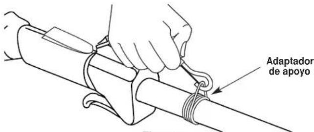
Raccord de soutienFigure 5
natural_image
Illustration of two hands holding a medical device with arrows indicating movement (no text or symbols)Figure 6
RETRAIT ET INSTALLATION DU PROTECTEUR D'ACCESSOIRE DE COUPE
natural_image
Illustration of a hand using a tool to cut or adjust a mechanical component (no text or symbols visible)Figure 9
Starting Instructions
INSTRUCTIONS D'ARRÊT
SECTION 6: MODE D'EMPLO
FONCTIONNEMENT DU EZ-Link ^MC
SECTION 6: MODE D'EMPLO
TENUE DE LA DÉSHERBEUSE

natural_image
Line drawing of a person using a manual lawn power shaver on grass (no text or symbols)Figure 22
RÉGLAGE DE LA LONGUEUR DU FIL
natural_image
Diagram of a mechanical lever system with grass and a downward arrow indicating motion (no text or symbols)Figure 23
SECTION 6: MODE D'EMPLO
COUPE DÉCORATIVE
natural_image
Line drawing of a person using a shoveling machine to spray plants (no text or symbols)Figure 25
natural_image
Illustration of two hand tools interacting with a blade and blade, surrounded by leafy materials (no text or symbols)Figure 26
SECTION 7: INSTRUCTIONS D'ENTRETIEN ET RÉPARATIONS
natural_image
Line drawing of a hand holding a circular mechanical component with a small inset showing a knob (no text or symbols)Figure 28
SECTION 7: INSTRUCTIONS D'ENTRETIEN ET RÉPARATIONS
natural_image
Illustration of two hands holding a ring-shaped object, one being adjusted by using a tool (no text or symbols present)Figure 40 Figure 39
SECTION 9: REMARQUES
text_image
YARD-MAN by MTDnatural_image
Technical line drawing of a metal detector with attached components (no text or symbols)text_image
MTD For A Growing World.natural_image
Line drawing of a person using a manual lawn pusher on grass (no text or symbols)Figure 3
natural_image
Diagram of a mechanical device with directional arrows indicating motion or force (no text or symbols present)Figure 4
natural_image
Illustration of two hands holding a medical device with arrows indicating movement (no text or symbols)Figure 6
natural_image
Illustration of a hand using a tool to lift a mechanical component (no text or symbols visible)Figure 9
natural_image
Illustration of a person using a manual lawn power shaver to clean grass (no text or symbols)Figure 22
AJUSTE DE LA LONGITUD DE LA LINEA DE CORTE
natural_image
Diagram of a mechanical tool with a downward arrow indicating compression or disassembly (no text or symbols present)Figure 23
natural_image
Illustration of a person using a manual shoveling machine to brush young plants (no text or symbols present)Figure 25
natural_image
Illustration of two hands operating a tool to interact with scattered leaves, no text or symbols presentFigure 26
natural_image
Line drawing of hands holding a mechanical component (no text or symbols)Figure 28
text_image
Bump HEAD No line Lazo Loween Bolt Bump HEAD No line Loween Bolt Loween Bolt RearbialsFigure 33
natural_image
Illustration of hands assembling a mechanical component with a spring and labeled 'Resorte' (no text or symbols on the diagram itself)Figure 35
natural_image
Illustration of two hands performing a manual tool manipulation (Figure 39 and Figure 40), no text or symbols present.Item Part No. Description
1 753-1192 Air Cleaner/Muffler Cover Assembly (includes 2 & 41)
2 791-180350B Air Cleaner Filter
3 791-180351 Carburetor Mounting Screw Assembly
4 753-04227 Choke Extension
5 753-1194 Choke Plate
6 753-04338 Carburetor Assembly (includes 7 & 18)
7 791-610675 Carburetor Gasket
8 791-181860 Carb Mount Screw
9 791-181558 Primer and Hose Assembly
10 791-182063 Carb Mount Assembly (includes 8 & 11)
11 791-684451 Reed Assembly
12 753-1208 Carburetor Mount Gasket
13 753-04332 Crank Case Service Assembly (includes 10)
14 791-612134 Rear Mounting Pad
15 753-04307 Fuel Tank Assembly (includes 16-18)
16 791-182612 Fuel Cap Assembly
17 791-181168 Fuel Return Line
18 753-04233 Fuel Line Assembly
19 791-145308 Front Mounting Pad
20 791-182064 Shroud Extension and Stand
21 791-182736 Flywheel Assembly
22 791-181065 Spacer
23 753-1199 Recoil Pulley Assembly
24 753-04286 Recoil Spring
25 753-1200 Rope Guide
26 753-04288 Pulley Retainer
27 791-181079 Pull Handle
28 791-613103 Rope
29 753-1201 Pressure Plate Assembly
30 7531202 Plate Screw
Item Part No. Description
31 753-04335 Starter Housing Assembly (includes 23-30 & 32)
32 791-181862 Housing Screw
33 791-182368 Clutch Washer
34 791-182369 Clutch Rotor Assembly
35 791-153592 Clutch Drum Assembly
36 753-1204 Clutch Cover Assembly (includes 41-44)
37 791-181345 Cover Screw
38 791-182519 Anti-Rotation Screw
39 753-04003 Clamping Screw
40 791-180217 Clamping Nut
41 791-182798 Wire Leads and Sleeve
42 791-611063 Ground Tab
43 753-04337 Module Assembly
44 791-610311B Spark Plug
45 791-182066 Muffler Assembly (includes 47-49)
46 791-182747 Spark Arrestor Screen
47 753-04159 Exhaust Gasket
48 791-147575 Muffler Mounting Bolt Assembly
49 753-04323 Cylinder Assembly (includes 52)
50 753-1207 Piston and Rod Assembly
51 753-1197 Cylinder Gasket
52 791-182723 Cylinder Bolt
* 791-180090 O.E.M. Carburetor Repair Kit (Zama)
* 791-180091 Gasket Diaphragm Repair Kit (Zama)
* 753-1209 Piston Ring Set
* 753-04334 Short Block Assembly (includes 8, 12, 14, 22, 48, 51-56)
* 791-181599 Clutch Springs (Qty. 2)
* 753-04134 Eng Gasket Kit
* Items Not Shown
PARTS LIST
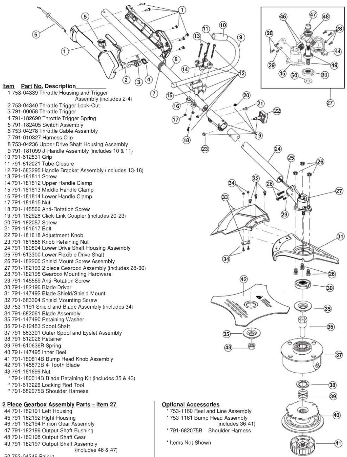
text_image
Item Part No. Description 1 753-04339 Throttle Housing and Trigger Assembly (includes 2-4) 2 753-04340 Throttle Trigger Lock-Out 3 791-00058 Throttle Trigger 4 791-182690 Throttle Trigger Spring 5 791-182405 Switch Assembly 6 753-04278 Throttle Cable Assembly 7 791-610327 Harness Clip 8 753-04236 Upper Drive Shaft Housing Assembly 9 791-181099 J-Handle Assembly (includes 10 & 11) 10 791-612831 Grip 11 791-612021 Tube Closure 12 791-683295 Handle Bracket Assembly (includes 13-18) 13 791-181811 Screw 14 791-181812 Upper Handle Clamp 15 791-181813 Middle Handle Clamp 16 791-181814 Lower Handle Clamp 17 791-181815 Nut 18 791-145569 Anti-Rotation Screw 19 791-182928 Click-Link Coupler (includes 20-23) 20 791-182057 Screw 21 791-181617 Bolt 22 791-181618 Adjustment Knob 23 791-181886 Knob Retaining Nut 24 791-180804 Lower Drive Shaft Housing Assembly 25 791-613300 Lower Flexible Drive Shaft 26 791-182200 Shield Mount Screw Assembly 27 791-182193 2 piece Gearbox Assembly (includes 28-30) 28 791-182195 Gearbox Mounting Hardware 29 791-145569 Anti-Rotation Screw 30 791-182196 Blade Driver 31 791-147492 Blade Shield/Shield Mount 32 791-683304 Shield Mounting Screw 33 753-1191 Shield and Blade Assembly (includes 34) 34 791-682061 Blade Assembly 35 791-147490 Retaining Washer 36 791-612483 Spool Shaft 37 791-683301 Outer Spool and Eyelet Assembly 38 791-612026 Retainer 39 791-610636B Spring 40 791-147495 Inner Reel 41 791-180814B Bump Head Knob Assembly 42 791-145873B 4-Tooth Blade 43 791-181699 Nut * 791-180014B Blade Retaining Kit (includes 35 & 43) * 791-613226 Locking Rod Tool * 791-682075B Shoulder Harness 2 Piece Gearbox Assembly Parts - Item 27 44 791-182191 Left Housing 45 791-182192 Right Housing 46 791-182194 Pinion Gear Assembly 47 791-182199 Output Shaft Bushing 48 791-182198 Output Shaft Gear 49 791-182197 Output Shaft Assembly (includes 46 & 47) Optional Accessories * 753-1160 Reel and Line Assembly * 753-1161 Bump Head Assembly (includes 36-41) * 791-682075B Shoulder Harness * Items Not ShownGARANTÍA LIMITADA DEL FABRICANTE PARA: