YM155 - Grass trimmer Yard-Man - Free user manual and instructions
Find the device manual for free YM155 Yard-Man in PDF.
| Product type | Battery-powered string trimmer (weed trimmer) |
| Brand | Yard-Man |
| Model | YM155 |
| Weight (with battery, guard, and handle) | 4.63 kg (10.2 lb) |
| Motor | 12 V DC, 15 A |
| Battery | Sealed rechargeable lead-acid, 12 V |
| Shaft | Aluminum |
| Cutting mechanism | Bump Head |
| Cutting swath diameter | 254 mm (10 in) |
| Line diameter | 2.03 mm (0.080 in) |
| Spool diameter | 76.2 mm (3 in) |
| Charger | 12 V (model 791-182534) with charging station |
| Charging time | Less than 24 h (10-38 °C); up to 48 h (4-10 °C) |
| Safety | Double insulation, overload protection switch, lockout button, cutting attachment guard |
| Applications | Cutting grass and light weeds, decorative trimming around trees, fences, etc. |
| Warranty | Limited 2-year warranty (90 days for commercial use) |
| Replacement parts available | Guard, line, spool, spring, bump head cover, charger, battery, etc. |
Frequently Asked Questions - YM155 Yard-Man
User questions about YM155 Yard-Man
0 question about this device. Answer the ones you know or ask your own.
Ask a new question about this device
Download the instructions for your Grass trimmer in PDF format for free! Find your manual YM155 - Yard-Man and take your electronic device back in hand. On this page are published all the documents necessary for the use of your device. YM155 by Yard-Man.
USER MANUAL YM155 Yard-Man
12 Volt Battery Trimmer
Model YM155
INTRODUCTION
THANK YOU
Thank you for buying this quality product. This modern outdoor power tool will provide many hours of useful service. You will find it to be a great labor-saving device. This operator's manual provides you with easy-to-understand operating instructions. Read the whole manual and follow all the instructions to keep your new outdoor power tool in top operating condition.
PRODUCT REFERENCES, ILLUSTRATIONS AND SPECIFICATIONS
All information, illustrations, and specifications in this manual are based on the latest product information available at the time of printing. We reserve the right to make changes at any time without notice.
Copyright © 2005 MTD SOUTHWEST INC, All Rights Reserved.
SERVICE INFORMATION
Service on this unit both within and after the warranty period should be performed only by an authorized and approved service dealer.
For service call 1-800-345-8746 in the United States, or 1-800-668-1238 in Canada to obtain a list of authorized service dealers near you. For more details about your unit, visit our website at www.Yardman.com.
If you have difficulty assembling this product or have any questions regarding the controls, operation or maintenance of this unit, please call the Customer Support Department.
DO NOT RETURN THE UNIT TO THE RETAILER. PROOF OF PURCHASE WILL BE REQUIRED FOR WARRANTY SERVICE.
TABLE OF CONTENTS
Service Information 2
Rules for Safe Operation 3
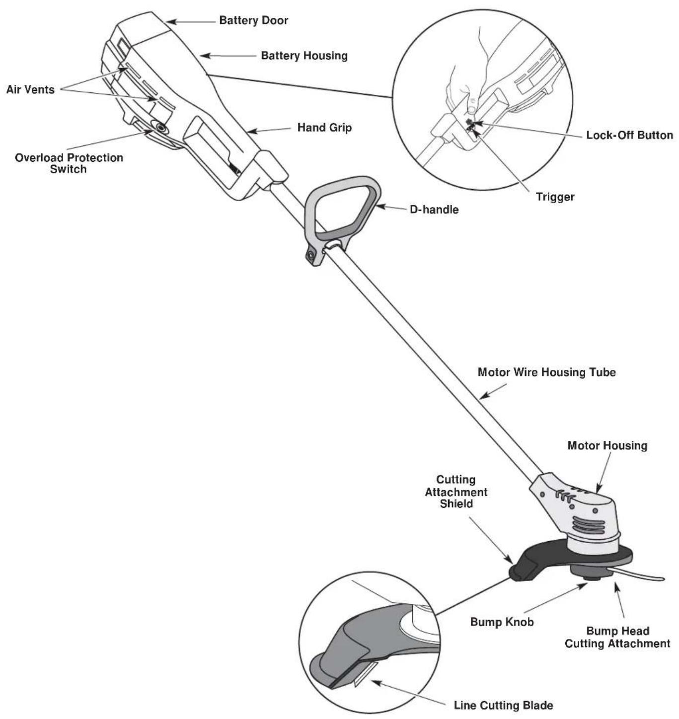
Know Your Unit 6
Assembly Instructions 7
Operating Instructions 8
Maintenance and Repair Instructions 11
Specifications 15
Troubleshooting Chart 15
Warranty Information 16
Parts List. .Inside Back Cover
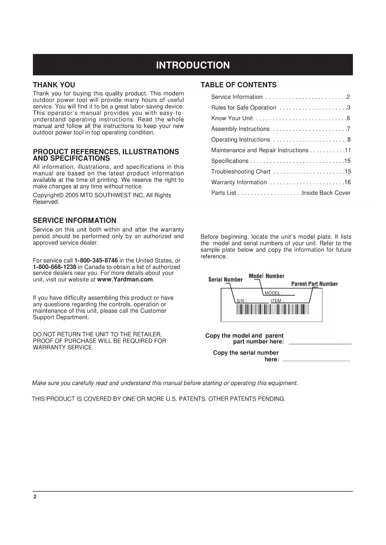
Before beginning, locate the unit's model plate. It lists the model and serial numbers of your unit. Refer to the sample plate below and copy the information for future reference.
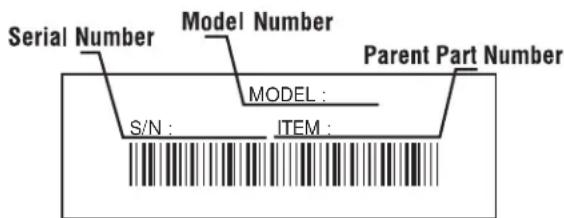
Copy the model and parent part number here:
Copy the serial number here:
Make sure you carefully read and understand this manual before starting or operating this equipment.
THIS PRODUCT IS COVERED BY ONE OR MORE U.S. PATENTS. OTHER PATENTS PENDING.
The purpose of safety symbols is to attract your attention to possible dangers. The safety symbols, and their explanations, deserve your careful attention and understanding. The safety warnings do not by themselves eliminate any danger. The instructions or warnings they give are not substitutes for proper accident prevention measures.
SYMBOL MEANING

SAFETY ALERT: Indicates danger, warning or caution. Attention is required in order to avoid serious personal injury. May be used in conjunction with other symbols or pictographs.
NOTE: Advises you of information or instructions vital to the operation or maintenance of the equipment.
Read the Operator's Manual(s) and follow all warnings and safety instructions.
Failure to do so can result in serious injury to the operator and/or bystanders.
FOR QUESTIONS, CALL 1-800-345-8746 in the
United States, or 1-800-668-1238 in Canada
SYMBOL MEANING

DANGER: Failure to obey a safety warning will result in serious injury to yourself or to others. Always follow the safety precautions to reduce the risk of fire, electric shock and personal injury.

WARNING: Failure to obey a safety warning can result in injury to yourself and others. Always follow the safety precautions to reduce the risk of fire, electric shock and personal injury.

CAUTION: Failure to obey a safety warning may result in property damage or personal injury to yourself or to others. Always follow the safety precautions to reduce the risk of fire, electric shock and personal injury.
- IMPORTANT SAFETY INSTRUCTIONS
READ ALL INSTRUCTIONS
BEFORE OPERATING

WARNING: When using battery trimmers, basic safety precautions should always be followed to reduce the risk of fire, electric shock and personal injury. Carefully read and understand the entire operator's manual before using your trimmer. Pay close attention to the operating instructions and safety warnings.
- Read the instructions carefully. Be familiar with the controls and proper use of the unit.
- Do not operate this unit when tired, ill or under the influence of alcohol, drugs or medication.
Children and teens under the age of 15 must not use the unit, except for teens guided by an adult. - Inspect the unit before use. Replace damaged parts. Check for battery leaks. Make sure all fasteners are in place and secure. Replace cutting attachment parts that are cracked, chipped or damaged in any way. Make sure the cutting attachment is properly installed and securely fastened. Be sure the cutting attachment shield is properly attached, and positioned as recommended. Failure to do so can result in personal injury to the operator and bystanders, as well as damage to the unit.
- Avoid dangerous environments. Never operate your unit in damp or wet conditions. Moisture is a shock hazard.
- Do not use the unit in the rain.
-
Do not handle the unit with wet hands.
-
Use only 0.080 inch (2.03 mm) diameter original equipment manufacturer replacement line. Never use metal-reinforced line, wire or rope. These can break off and become dangerous projectiles.
- Be aware of the risk of injury to the head, hands and feet.
- Clear the area to be cut before each use. Remove all objects such as rocks, broken glass, nails, wire or string. They can be thrown or become entangled in the cutting attachment. Clear the area of children, bystanders, and pets. At a minimum, keep all children, bystanders and pets outside a 50-foot (15 m.) radius; there still may be a risk to bystanders from thrown objects. Bystanders should be encouraged to wear eye protection. If you are approached, stop the motor and cutting attachment immediately.
- This unit was not designed to be used as a brushcutter. Do not attach or operate this unit with any type of brushcutting blade or brushcutting attachment.
SAFETY WARNINGS FOR BATTERY TRIMMERS
- Battery tools do not have to be plugged into an electrical outlet; therefore, they are always in operating condition. Be aware of possible hazards even when the tool is idle. Take care when performing maintenance or service.
- Remove or disconnect the battery before servicing, cleaning or removing material from the unit.
- Only use the charging station provided with your unit. Do not substitute any other charging equipment. Use of any other means of charging could cause the batteries to explode, resulting in possible serious personal injury.
- Do not charge the unit in the rain or in wet locations.
- Before using the charging stand, read all instructions and cautions in this manual, as well as on the charging stand, and on the unit.
- Do not expose charger to rain or snow.
- To reduce risk of injury, charge only sealed lead-acid rechargeable batteries. Other types of batteries may burst, causing personal injury and damage.
- To reduce risk of damage to charger body and cord, pull it by the charger body (not the cord) when disconnecting the charger.
- Make sure the charger cord is located in an area where it will not be stepped on, tripped over or otherwise subjected to damage or stress.
- D o not operate the charger with a damaged cord or plug. If damaged, replaced the charger immediately.
- Do not operate charger if it has received a sharp blow, been dropped or has been damaged in any way. If the charger case is damaged, replace the charger.
- Do not disassemble the charger. The charger is not serviceable; disassembly may result in an electric shock or fire.
- To reduce the risk of electric shock, unplug the charger from the outlet before you clean or service the unit.
- Do not use the charger outdoors.
- Use only the following type and size battery: 12 volt DC, sealed lead-acid battery (182391).
- Do not dispose of batteries in fire. The cell may explode. Batteries should be recycled. Consult your local waste authority for information regarding available recycling and/or disposal options.
Exercise care when handling the batteries. Be careful and avoid shorting the battery with conducting materials like rings, brackets and keys. The battery or conductor may overheat and cause burns. - Charge the battery in a location where the temperature is between 50^ (10^) and 100^ (38^) .
- Do not open or mutilate the battery. Released electrolyte is corrosive and may cause damage to the eyes or skin. It may be toxic if swallowed.
WHILE OPERATING
- Wear safety glasses or goggles that are marked as meeting ANSI Z87.1-1989 standards, and ear/hearing protection when operating this unit. Wear a face or dust mask if the operation is dusty. Long sleeve shirts are recommended.
- Wear heavy, long pants, boots and gloves. Do not wear loose clothing, jewelry, short pants, sandals or go barefoot. Secure hair above shoulder level.
- The cutting attachment shield must always be in place while operating the unit. Do not operate unit without the trimming lines extended, and the proper line installed. Do not extend the trimming line beyond the length of the shield.
-
Adjust the D-handle to your size to provide the best grip.
-
Be sure the cutting attachment is not in contact with anything before starting the unit.
- Use the unit only in daylight or good artificial light.
- Avoid accidental starting. Do not carry around a unit with your finger on the trigger switch.
- Use the right tool. Only use this tool for the purpose intended.
- Do not overreach. Always keep proper footing and balance.
Always hold the unit with both hands when operating. Keep a firm grip on both the battery housing grip and the D-handle.
- Keep hands, face and feet at a distance from all moving parts. Do not touch or try to stop the cutting attachment when it is rotating.
- Do not operate the motor faster than the speed needed to cut, trim or edge. Do not run the motor at high speed when you are not cutting.
Always stop the motor when cutting is delayed or when walking from one cutting location to another. - If you strike or become entangled with a foreign object, stop the motor immediately and check for damage. Do not operate before repairing damage. Do not operate the unit with loose or damaged parts.
- Release the trigger, ensure the lock-off button resets and allow the motor to stop for maintenance or repair.
- Use only original equipment manufacturer replacement parts when servicing this unit. These parts are available from your authorized service dealer. Do not use unauthorized parts, accessories or attachments. Using unauthorized parts may lead to serious injury, damage to the unit and a voided warranty.
- Keep the unit clean of vegetation and other materials. They may become lodged between the cutting attachment and shield.
OTHER SAFETY WARNINGS
- Disconnect the unit from the power supply when it is idle, when you are storing or transporting it, when you are servicing it, and when you are changing attachments.
- Store the unit in a dry area, locked up to prevent unauthorized use or damage, and stored in a high place out of the reach of children.
- Never douse or squirt the unit with water or any other liquid. Keep handles dry, clean and free from debris. Clean after each use. See the Cleaning and Storage instructions.
- Keep these instructions. Refer to them often and use them to instruct other users. If you loan someone this unit, also loan them these instructions.
SAVE THESE INSTRUCTIONS
SAFETY AND INTERNATIONAL SYMBOLS
This operator's manual describes safety and international symbols and pictographs that may appear on this product. Read the operator's manual for complete safety, assembly, operating and maintenance and repair information.
SYMBOL MEANING

- SAFETY ALERT SYMBOL
Indicates danger, warning or caution. May be used in conjunction with other symbols or pictographs.

- WARNING - READ OPERATOR'S MANUAL
Read the operator's manual(s) and follow all warnings and safety instructions. Failure to do so can result in serious injury to the operator and/or bystanders.

- WEAR EYE AND HEARING PROTECTION
WARNING: Thrown objects and loud noise can cause severe eye injury and hearing loss. Wear eye protection meeting ANSI Z87.1 standards and ear protection when operating this unit. Use a full face shield when needed.
SYMBOL MEANING
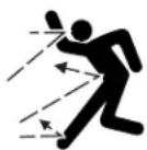
- THROWN OBJECTS AND ROTATING CUTTER CAN CAUSE SEVERE INJURY
WARNING: Do not operate without the cutting attachment shield in place. Keep away from the rotating cutting attachment.

SHARP BLADE
WARNING: Sharp blade on cutting attachment shield. To prevent serious injury, do not touch line cutting blade.
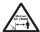
- KEEP BYSTANDERS AWAY
WARNING: Keep all bystanders, especially children and pets, at least 50 feet (15 m) from the operating area.
Cutting grass and light weeds
- Decorative trimming around trees, fences, etc.
ASSEMBLY INSTRUCTIONS
ADJUSTING THE D-HANDLE
NOTE: The D-handle comes mounted on the backside of the shaft.
- Locate the wing nut on the D-Handle. Untighten the wing nut enough to loosen the D-Handle (Fig. 1).
NOTE: Do not remove wing nut, washer, or bolt. - Rotate the D-Handle to the upright position on the front side of the shaft housing (Fig. 1).
NOTE: The D-handle should slant towards the powerhead of the unit.
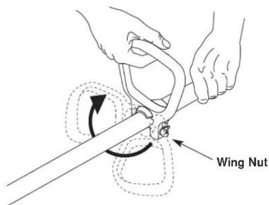
Fig. 1
- Hold the unit in the operating position. If necessary, reposition the D-handle to the location that provides the best grip (Fig. 2).
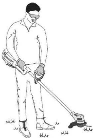
Fig. 2
- Tighten the wing nut until the D-Handle is secure.
MOUNTING THE CHARGING STATION
NOTE: Mount the charging unit and allow the unit to charge for at least 36 hours prior to first use.
This unit may stay on the charging station continuously without overcharging. Place the charging station where the unit is intended to be stored. This should be a cool, dry and well ventilated place, where the unit can be locked-up and out of the reach of children.
The unit should be stored and charged in a location where the temperature is between 50^ (10^) and 100^ (38^) .
- Locate a place for the charging station near a wall outlet and high enough to keep the unit off the floor.
- Locate the wall stud and mount the charging station to the wall using the three (3) screws provided (Fig 3). Make sure that the screws enter the wall stud to provide a secure mount.
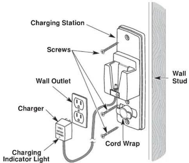
Fig. 3

CAUTION: To prevent injury or damage to the unit, the charging station must be mounted securely to the wall.
- Plug the charger into the wall outlet and wind any excess wire onto the cord wrap on the charging station (Fig. 3).
OPERATING INSTRUCTIONS
CHARGING THE UNIT
Make sure the charging station is securely fastened to a wall and the charger is plugged into a working wall outlet.
NOTE: Allow the unit to charge for at least 36 hours prior to first use.
- Slide the unit down into the charging station until it is firmly seated (Fig. 4). The barrel connector in the charging station will insert into the unit. If it doesn't, refer to Replacing the Charger.
NOTE: The battery will heat up while the unit charges. Be sure the air vents on the battery housing are kept clear for proper ventilation (Fig. 4).
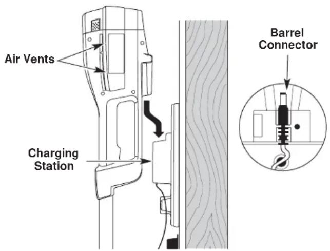
Fig. 4
- When the red indicator light on the charger is on, the battery is being charged (Fig. 5). If the light fails to come on, check that:
a. The charger is plugged into a working wall outlet.
b. The unit is firmly seated into the charging station and the barrel connector is fully inserted into the unit.
c. The barrel connector is properly installed in the charging station. If it isn't, refer to Replacing the Charger.
d. Power is on at the wall outlet.
NOTE: If the wall outlet is operated by a switch, be sure the switch is ON.

WARNING: If the wall outlet is not working properly, have the wall outlet checked by a qualified electrician. This will help prevent serious personal injury.
- Charge the battery until the Charging Indicator Light on the charger turns from red to green (Fig. 5).
NOTE: The unit's operating time and the life of the battery will be shorter if the unit is not fully charged between uses. - Place the unit back on the charging station after each use. The unit is designed so that the battery cannot be overcharged.
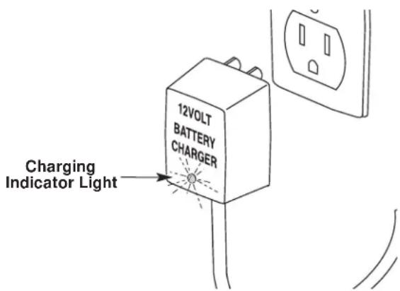
Fig. 5
Charging Tips for Maximum Performance
- Store and charge the unit where temperatures are between 50^ F (10^ C) and 100^ F (38^ C). Storing the unit or batteries above 100^ F (38^ C) will reduce battery life.
- Storage below 50^ F (10^) will not reduce battery life, but may require a longer charging time.
- Store the unit on the charging station when not in use. The unit is designed so that the battery cannot be overcharged.
NOTE: The charging indicator light will remain lit when the unit is properly installed in the charging station.
Temperature Effects on Charging Time
- 50^ F (10°C) to 100° F (38°C) - Battery will charge within 24 hours.
- 40^ F (4°C) to 50^ F (10°C) - Battery will require up to 48 hours for a full charge.
Below 40^ F (4^) Battery will not reach full charge.
NOTE: The unit run time will be reduced when the battery is not fully charged.
OPERATING INSTRUCTIONS
STARTING THE UNIT
- Press and hold the lock-off button in (Fig. 6). This allows the trigger to operate.

WARNING: To prevent serious personal injury, ensure the lock-off button resets each time the trigger is released.
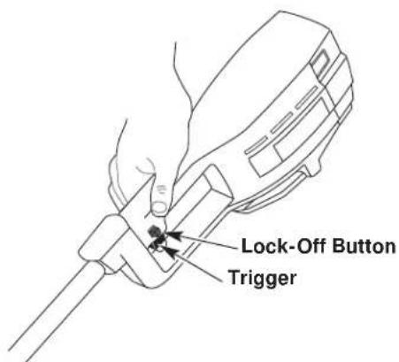
Fig. 6
- Depress and hold the trigger.
- Release the lock-off button.
STOPPING THE UNIT
Release the trigger to stop the trimmer.
OVERLOAD PROTECTION SWITCH
This unit is equipped with an overload protection switch to prevent overheating damage to the motor.
If the switch pops out:
- Release the trigger and allow the unit to cool for a minute.
- Press the overload switch to reset. Resume operation (Fig. 7).
If the switch pops again shortly after the first time:
- Allow the unit to cool for 15 to 30 minutes.
- After the unit has cooled, press the overload switch to reset. Resume operation
If the switch does not stay in or continues to pop out during operation, take the unit to an authorized service dealer for repair.
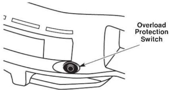
Fig. 7
HOLDING THE UNIT

WARNING: Dress properly to reduce the risk of injury when operating this unit. Do not wear loose clothing or jewelry. Wear eye and ear/hearing protection. Wear heavy, long pants, boots and gloves. Do not wear short pants, sandals or go barefoot.
Before operating the unit, stand in the operating position and check that:
- The operator is wearing eye protection and proper clothing.
The operator's right arm is slightly bent, the right hand holding the housing grip. - W ith a straight left arm, the left hand holding the D-handle.
The unit is at waist level. - The trimmer bump head is parallel to the ground and easily contacts the material to be cut without the operator having to bend over (Fig. 8).
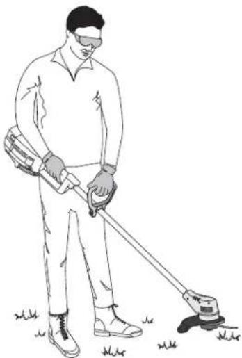
Fig. 8

WARNING: To prevent serious injury, do not carry the unit with your finger on the trigger.
OPERATING INSTRUCTIONS
WARNING: Always wear eye, hearing, foot and body protection to reduce the risk of injury when operating this unit.
Clear the area to be cut before each use. Remove all objects such as rocks, broken glass, nails, wire, or string which can be thrown or become entangled in the cutting attachment. Clear the area of children, bystanders, and pets. At a minimum, keep all children, bystanders and pets outside a 50 feet (15m) radius; there still may be a risk to bystanders from thrown objects. Bystanders should be encouraged to wear eye protection. If you are approached, stop the motor and cutting attachment immediately.
NOTE: Remove protective tape from the line cut-off blade before operating trimmer.
ADJUSTING TRIMMING LINE LENGTH
The bump head allows the operator to release more trimming line without stopping the motor. As line becomes frayed or worn, additional line can be released by lightly tapping the trimming head on the ground while operating the trimmer (Fig. 9).
Fig. 9
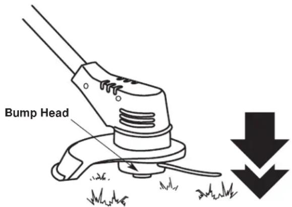
NOTE: Always keep the trimming line fully extended. Line release becomes more difficult as cutting line becomes shorter.

CAUTION: Do not remove or alter the line cutting blade assembly. Excessive line length will make the unit overheat. This may lead to serious personal injury or damage to the unit.
Each time the head is bumped, approximately 1 inch (25.4 mm) of trimming line is released. A blade in the string guard will cut the line if excess line is released. For best results, tap the head on bare ground or hard soil. If line release is attempted in tall grass, the motor may overheat. Always keep the trimming line fully extended. Line release becomes more difficult as the cutting line becomes shorter.
TIPS FOR BEST TRIMMING RESULTS
- Keep the cutting attachment parallel to the ground.
- Do not force the cutting attachment. Allow the tip of the line to do the cutting, especially along walls. Cutting with more than the tip will reduce cutting efficiency and may overload the motor.
- Cut grass over 8 inches (200 mm) by working from top to bottom in small increments to avoid premature line wear or motor drag.
- Cut from right to left whenever possible. Cutting to the left improves the unit's cutting efficiency. Clippings are thrown away from the operator.
- Slowly move the trimmer into and out of the cutting area at the desired height. Move either in a forward-backward or side-to-side motion. Cutting shorter lengths produces the best results.
- Trim only when grass and weeds are dry.
-
The life of your cutting line is dependent upon:
-
Following the trimming techniques previously explained
What vegetation is cut
Where vegetation is cut
For example, the line will wear faster when trimming against a foundation wall as opposed to trimming around a tree.
DECORATIVE TRIMMING
Decorative trimming is accomplished by removing all vegetation around trees, posts, fences and more. Rotate the whole unit so that the cutting attachment is at a 30^ angle to the ground (Fig. 10).
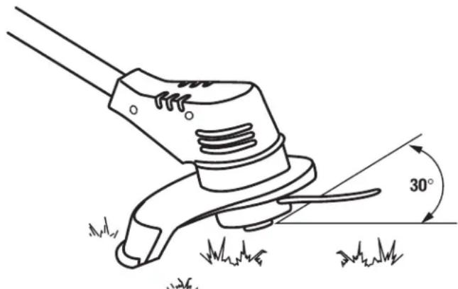
Fig. 10
MAINTENANCE AND REPAIR INSTRUCTIONS
The warranty on this unit does not cover items that have been subjected to operator abuse or negligence. To receive full value from the warranty, the operator must maintain the unit as instructed in this operator's manual.

WARNING: Battery tools do not have to be plugged into an electrical outlet; therefore, they are always in operating condition. To prevent serious personal injury, take extra precaution and care when performing maintenance or repair.

WARNING: To prevent serious personal injury, remove or disconnect the battery before servicing, cleaning or removing material from the unit.
SERVICING DOUBLE INSULATED UNITS
This unit is double-insulated. In a double-insulated unit, two systems of insulation are provided instead of grounding. There is no grounding provided and no means of grounding should be added to this unit. Extreme care and knowledge of the system is required when servicing a double-insulated unit. Service should be performed by qualified service personnel only. Replacement parts for a double-insulated unit must be identical to the parts they replace. Refer any repair to an authorized service dealer. A double-insulated unit is marked with the words "double insulation" or "double insulated."
LINE INSTALLATION

WARNING: Never use metal-reinforced line, wire, chain or rope. These can break off and become dangerous projectiles.
Always use genuine original equipment manufacturer 0.080 in. (2.03 mm.) replacement line. Using line other than specified may cause the unit to overheat or fail.
There are two methods to replace the trimmer line:
W ind the inner reel with new line
Install a prewound inner reel
Winding the Existing Reel
- Remove the bump head cover by pressing in both bump head cover tabs visible on either side of the bump head outer spool (Fig. 11).
NOTE: The spring will push the cover up when the tabs release.
- Remove the inner reel and spring (Fig. 11).
- Use a clean cloth to wipe the inner surface of the outer spool (Fig. 11).
NOTE: Always clean the inner reel, outer spool and shaft before reassembling the bump head.
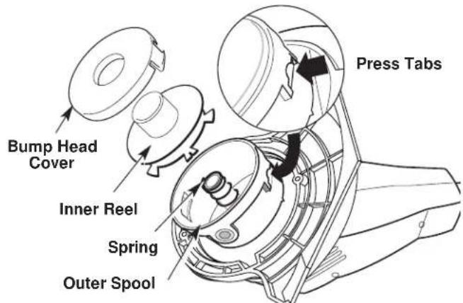
Fig. 11
- Check the indexing teeth on the inner reel and outer spool for wear (Fig. 12). If necessary, remove burrs or replace the reel and spool.
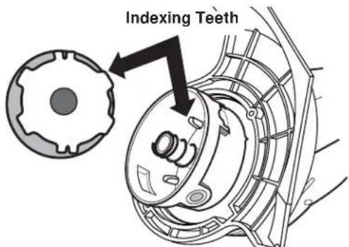
Fig. 12
- Take approximately 12 feet (3.6m) of new trimming line and insert one end of the line into the hole in the inner reel (Fig. 13).
- Wind the line, in even and tight layers, onto the reel (Fig. 13). Wind the line in the direction indicated on the inner reel.
NOTE: Failure to wind the line in the direction indicated will cause the bump head to operate incorrectly.
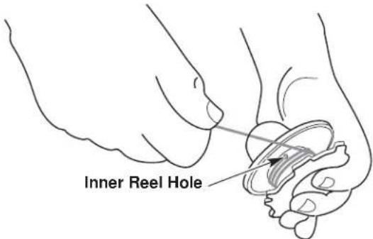
Fig. 13
MAINTENANCE AND REPAIR INSTRUCTIONS
- Insert the end of the line into one of the two holding slots (Fig. 14).
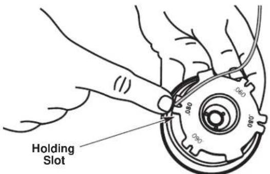
Fig. 14
- Insert the end of the line through the eyelet in the outer spool (Fig. 15).
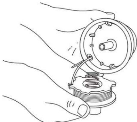
Fig. 15
- Place inner reel and spring inside the outer spool.
NOTE: The spring must be assembled on the inner reel before reassembling the bump head. - Hold the inner reel in place, grasp the line end and pull firmly to release the line from the holding slot in the inner reel (Fig. 16).
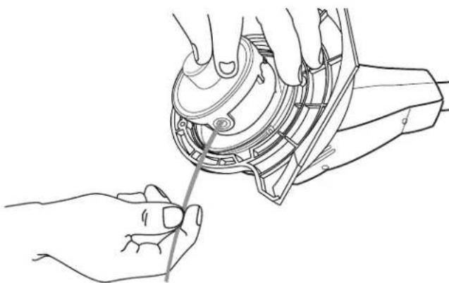
Fig. 16
- Install the bump head cover over the inner reel. Align the tabs on the cover with the slots in the outer spool and press the cover evenly down until it snaps into place.
NOTE: Make sure the bump head cover tabs snap into place or the inner reel will come out during operation.
INSTALLING A PREWOUND REEL
Always use genuine replacement line. Using larger line then the specified may make the motor overheat or fail.
- Remove the bump head cover by pressing in both bump head cover tabs visible on either side of the bump head outer spool (Fig. 11).
NOTE: The spring will push the cover up when the tabs release. - Remove the old inner reel and spring from the outer spool (Fig. 11).
- Remove the spring from the old inner reel (Fig. 11).
- Use a clean cloth to wipe the inner surface of the outer spool.
- Insert the end of the line, on the prewound reel, through the eyelet in the outer spool (Fig. 15).
- Place inner reel and spring inside the outer spool.
NOTE: The spring must be assembled on the inner reel before reassembling the bump head. - Hold the inner reel in place, grasp the line end and pull firmly to release the line from the holding slot in the inner reel (Fig. 16).
- Install the bump head cover over the inner reel. Align the tabs on the cover with the slots in the outer spool and press the cover evenly down until it snaps into place.
NOTE: Make sure the bump head cover tabs snap into place or the inner reel will come out during operation.
MAINTENANCE AND REPAIR INSTRUCTIONS
BATTERY PACK REPLACEMENT
| Pb | To preserve natural resources, please recycle or dispose of properly. THIS PRODUCT CONTAINS A SEATED LEAD-ACID BATTERY AND MUST BE DISPOSED OF PROPERLY. Local, state, or federal laws may prohibit disposal of sealed lead-acid batteries in ordinary trash. Consult your local waste authority for information regarding available recycling and/or disposal options. |
Removing the Battery
- Push the two latches on the side of the battery housing door in and swing the door down. Unhook the door from the slot on the bottom of the battery housing by lifting up and away. Set the door aside (Fig. 17).
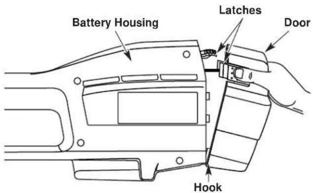
Fig. 17
- Push down on the battery retaining latch while pulling battery out (Fig. 18).
NOTE: You might notice grease on the terminal contacts when the battery is removed. This is normal.
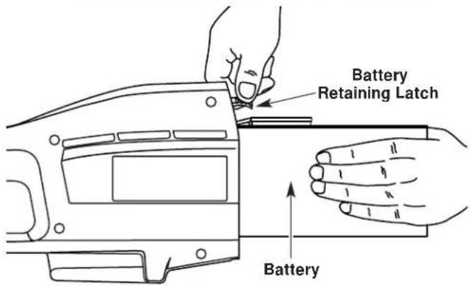
Fig. 18

WARNING: If the battery pack has signs of leakage, do not touch. Do not open or mutilate the battery. Released electrolyte is corrosive and may cause damage to the eyes or skin. To avoid serious injury, take the unit to an authorized service dealer for repair.
Installing the Battery
- Slide the battery into the battery housing until the battery retaining latch locks the battery into place (Fig 18).
- Reinstall the door by hooking over the slot on the bottom of the battery housing. Swing the battery housing door closed until the two latches snap into place.
For best performance when reinstalling the battery:
- Check the battery terminals for corrosion and clean them if necessary. Clean the terminals using a dry scrubbing pad and wipe clean with a dry cloth. Never use liquids to clean terminals.
- Check the battery casing for signs of damage and replace it if needed.
NOTE: If you clean or replace the battery, apply a small amount of electrically conductive grease to the terminals only. This grease is available at any local electronics store. Do not use automotive or bearing grease.
Storing the Battery Pack
If you are removing the battery for replacement or for storage, cover the battery pack's terminals with heavy duty electrical tape.

WARNING: Do not attempt to destroy or disassemble battery or remove any of its components. Sealed lead-acid batteries must be recycled or disposed of properly. Never touch both terminals with metal objects and/or body parts, a short circuit may result. Keep away from children. Failure to comply with these warnings could result in fire and/or serious personal injury.
MAINTENANCE AND REPAIR INSTRUCTIONS
REPLACING THE CHARGER
Replace the charger if it is damaged, if the barrel connector or cord become damaged, or if the barrel connector is not contacting the unit properly.

CAUTION: Only use the type of charger specified for this unit. Any other type may cause damage to the unit, damage to the batteries or possible injury.
Your trimmer requires a 12V charger (791-182534) and charging station (791-180295). The charging instructions refer only to these parts.
- Unplug the charger from the wall outlet and remove the unit from the charging station.
- Remove the screw from the clamp holding the barrel connector in place using a standard or T-20 Torx bit screwdriver (Fig. 19).
- Remove the barrel connector from the slot and replace the charger, if needed.
- Insert the narrow side of the barrel connector wire into the groove in the slot of the charging station. Ensure that the barrel connector is inserted correctly and secure (Fig. 19).
- Reinstall the clamp and screw.
- Plug the charger into the wall outlet. Refer to Charging the Unit for charging instructions.
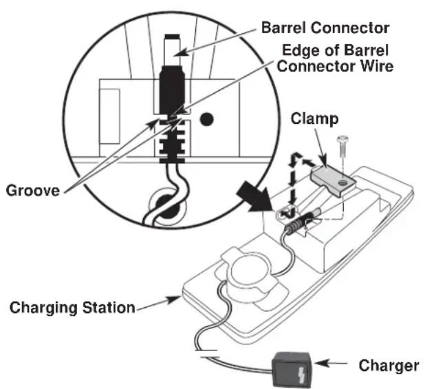
Fig. 19
CLEANING

WARNING: To prevent serious personal injury, remove or disconnect the battery before servicing, cleaning or removing material from the unit.

WARNING: Battery tools do not have to be plugged into an electrical outlet; therefore, they are always in operating condition. To prevent serious personal injury, take extra precaution and care when cleaning the unit.
Switch off the unit and disconnect it from the power source. Use a small brush to clean off the outside of the unit. Do not use strong detergents. Household cleaners that contain aromatic oils such as pine and lemon, and solvents such as kerosene, can damage plastic housing or handle. Wipe off any moisture with a soft cloth. Also keep the air vents free of obstructions.
STORAGE
- Allow the unit to cool before storing.
- Lock the unit to prevent unauthorized use or damage.
- Store the unit in a dry, well-ventilated area.
- Store the unit out of the reach of children.
ACCESSORIES AND REPLACEMENT PARTS
Cutting Attachment Shield 180293
Replacement Line 610375
Replacement Line Cartridge 180292
Inner Reel Spring 180374
Bump Head Cover 180376
Charger 182534
Charging Station 180295
12 Volt Battery Pack 791-182391B
TROUBLESHOOTING
Battery is not charged Charge the battery
Overload protection switch has popped Reset overload protection switch
BATTERY WILL NOT CHARGE
CAUSE ACTION
No power to charger or battery Check charger and charging station
Battery has failed Replace the battery
CUTTING ATTACHMENT WILL NOT ADVANCE LINE
CAUSE ACTION
Cutting attachment bound with grass Stop the unit and clean cutting attachment
Cutting attachment out of line Refill with new line
Inner reel bound up Replace the inner reel
Cutting attachment dirty Clean inner reel and outer spool
Line welded Disassemble, remove the welded section
and rewind the line
Line twisted when refilled Disassemble and rewind the line
Not enough line is exposed Push the Bump Knob and pull out line until
4 inches (102 mm.) of line is outside of the
cutting attachment
SPECIFICATIONS
BATTERY AND MOTOR
Motor 12 Volt DC, 15 Amps
Battery. Sealed Lead-Acid, 12 Volt
Motor Wire Housing Tube. Aluminum Tube
Unit Weight (With battery, cutting attachment shield and D-handle) 10.2 lbs. (4.63 kg.)
Cutting Mechanism. Bump Head
Line Spool Diameter. 3 in (76.2 mm)
Trimming Line Diameter 0.080 in (2.03 mm.)
Cutting Path Diameter. 10 in. (254 mm)
MANUFACTURER'S LIMITED WARRANTY FOR:

The limited warranty set forth below is given by MTD LLC ("MTD") with respect to new merchandise purchased and used in the United States, its possessions and territories.
MTD warrants this product against defects in material and workmanship for a period of two (2) years commencing on the date of original purchase and will, at its option, repair or replace, free of charge, any part found to be defective in material or workmanship. This limited warranty shall only apply if this product has been operated and maintained in accordance with the Operator's Manual furnished with the product, and has not been subject to misuse, abuse, commercial use, neglect, accident, improper maintenance, alteration, vandalism, theft, fire, water or damage because of other peril or natural disaster. Damage resulting from the installation or use of any accessory or attachment not approved by MTD for use with the product(s) covered by this manual will void your warranty as to any resulting damage. This warranty is limited to ninety (90) days from the date of original retail purchase for any MTD product that is used for rental or commercial purposes, or any other income-producing purpose.
HOW TO OBTAIN SERVICE: Warranty service is available, WITH PROOF OF PURCHASE THROUGH YOUR LOCAL AUTHORIZED SERVICE DEALER. To locate the dealer in your area, please check for a listing in the Yellow Pages or contact the Customer Service Department of MTD LLC by calling 1-800-345-8746 or writing to P.O. Box 361131, Cleveland OH 44136-0019 or if in Canada call 1-800-668-1238. No product returned directly to the factory will be accepted unless prior written permission has been extended by the Customer Service Department of MTD LLC.
This limited warranty does not provide coverage in the following cases:
A. Tune-ups - Spark Plugs, Carburetor Adjustments, Filters.
B. Wear items - Bump Knobs, Outer Spools, Cutting Line, Inner Reels, Starter Pulley, Starter Ropes, Drive Belts.
C. MTD does not extend any warranty for products sold or exported outside of the United States of America, its possessions and territories, except those sold through MTD's authorized channels of export distribution.
MTD reserves the right to change or improve the design of any MTD Product without assuming any obligation to modify any product previously manufactured.
No implied warranty, including any implied warranty of merchantability or fitness for a particular purpose, applies after the applicable period of express written warranty above as to the parts as identified. No other express warranty or guaranty, whether written or oral, except as mentioned above, given by any person or entity, including a dealer or retailer, with respect to any product shall bind MTD. During the period of the Warranty, the exclusive remedy is repair or replacement of the product as set forth above. (Some states do not allow limitations on how long an implied warranty lasts, so the above limitation may not apply to you.)
The provisions as set forth in this Warranty provide the sole and exclusive remedy arising from the sales. MTD shall not be liable for incidental or consequential loss or damages including, without limitation, expenses incurred for substitute or replacement lawn care services, for transportation or for related expenses, or for rental expenses to temporarily replace a warranted product. (Some states do not allow limitations on how long an implied warranty lasts, so the above limitation may not apply to you.)
In no event shall recovery of any kind be greater than the amount of the purchase price of the product sold. Alteration of the safety features of the product shall void this Warranty. You assume the risk and liability for loss, damage, or injury to you and your property and/or to others and their property arising out of the use or misuse or inability to use the product.
This limited warranty shall not extend to anyone other than the original purchaser, original lessee or the person for whom it was purchased as a gift.
How State Law Relates to this Warranty: This warranty gives you specific legal rights, and you may also have other rights which vary from state to state.
To locate your nearest service dealer dial 1-800-345-8746 in the United States or 1-800-668-1238 in Canada.
MTD LLC
P.O.Box 361131
Cleveland, OH 44136-0019
YaRD-Man
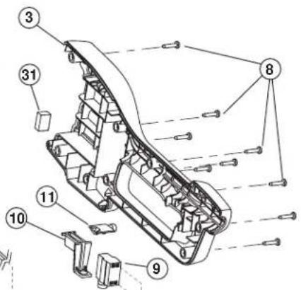
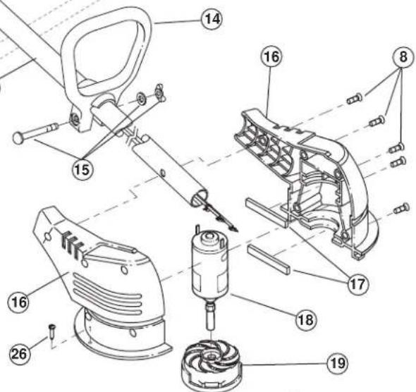
REPLACEMENT PARTS-MODEL YM155
12 VOLT BATTERY TRIMMER
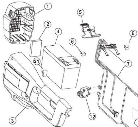
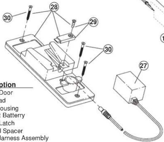
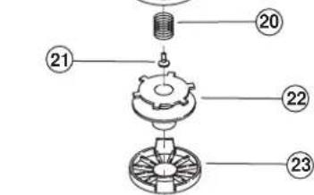
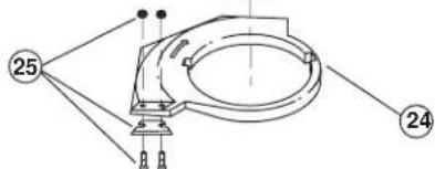
Item Part No. Description
1791-182696 Battery Door
2791-182542 Foam Pad
3 753-05062 Battery Housing
4 791-182391B 12 Volt Battery
5 791-182699 Battery Latch
6 791-182702 Terminal Spacer
7 791-182724 Wiring Harness Assembly
8791-181482 Housing Screw
9791-180150 Switch Assembly (includes 10)
10 791-182318 Trigger
11 791-180364 Lock-Off Button
12 791-180365 Circuit Breaker
13 791-180367 Motor Wire Tube
14 791-153064 D-Handle (includes 15)
15 791-181587 Handle Hardware
16 753-05066 Motor Housing
17 791-180369 Spacer
18 791-182715 Motor with Shaft
19 791-180372 Outer Spool and Eyelet/Motor Fan
20791-180374 Spring
21753-04010 Screw
22 791-180292B Inner Reel with .080" Line
23 791-180376 Reel Cover
24 791-180293 Guard Assembly (includes 25)
25 791-180377 Blade Assembly
26 753-1202 Guard Screw
27 791-182534 12 Volt Charger
28 791-180295 Charging Station Stand (includes 29 & 30
29 791-180378 Barrel Clamp with Screw
30 791-182709 Mounting Screw
31 753-04007 Front Battery Pads
Optional Accessories
-
791-610375 Replacement Line (.080 Diameter)
-
791-180327 Bump Head Assembly (includes 20-24))

CAUTION: Only authorized service technicians should perform adjustments to double-insulated units.
GARANTÍA LIMITADA DEL FABRICANTE PARA: