AVICZ7210DAB - GPS Navigation System PIONEER - Free user manual and instructions
Find the device manual for free AVICZ7210DAB PIONEER in PDF.
| Brand | Pioneer |
| Model | AVICZ7210DAB |
| Product Type | GPS navigation system with DAB digital radio |
| Power Supply | 12 V DC, negative ground |
| Fuse | 10 A |
| Speaker Impedance | 4 Ω to 8 Ω (50 W max per channel) |
| Navigation Functions | GPS guidance, map display, points of interest, voice guidance |
| DAB Radio | Digital radio reception (DAB/DAB+) |
| Connectivity | Bluetooth, USB (2 ports), AUX, video input (RCA), rear view camera |
| Compatibility | Apple CarPlay, Android Auto, iPod/iPhone, Android smartphones |
| Number of Audio Channels | 4 channels (front, rear) + subwoofer output |
| Rear Video Output | Yes, for auxiliary screen |
| GPS Antenna | Cable length 3.55 m |
| Microphone | Cable length 3 m, adjustable |
| Maintenance and Cleaning | Clean with a soft, dry cloth. Do not use chemicals. |
| Safety | Do not use while driving (except navigation). Secure firmly, do not obstruct airbags. |
| Installation | Professional installation recommended. Requires ACC position on vehicle. |
| Spare Parts and Repairability | Do not repair yourself. Contact a Pioneer authorized technician. |
Frequently Asked Questions - AVICZ7210DAB PIONEER
User questions about AVICZ7210DAB PIONEER
0 question about this device. Answer the ones you know or ask your own.
Ask a new question about this device
Download the instructions for your GPS Navigation System in PDF format for free! Find your manual AVICZ7210DAB - PIONEER and take your electronic device back in hand. On this page are published all the documents necessary for the use of your device. AVICZ7210DAB by PIONEER.
USER MANUAL AVICZ7210DAB PIONEER
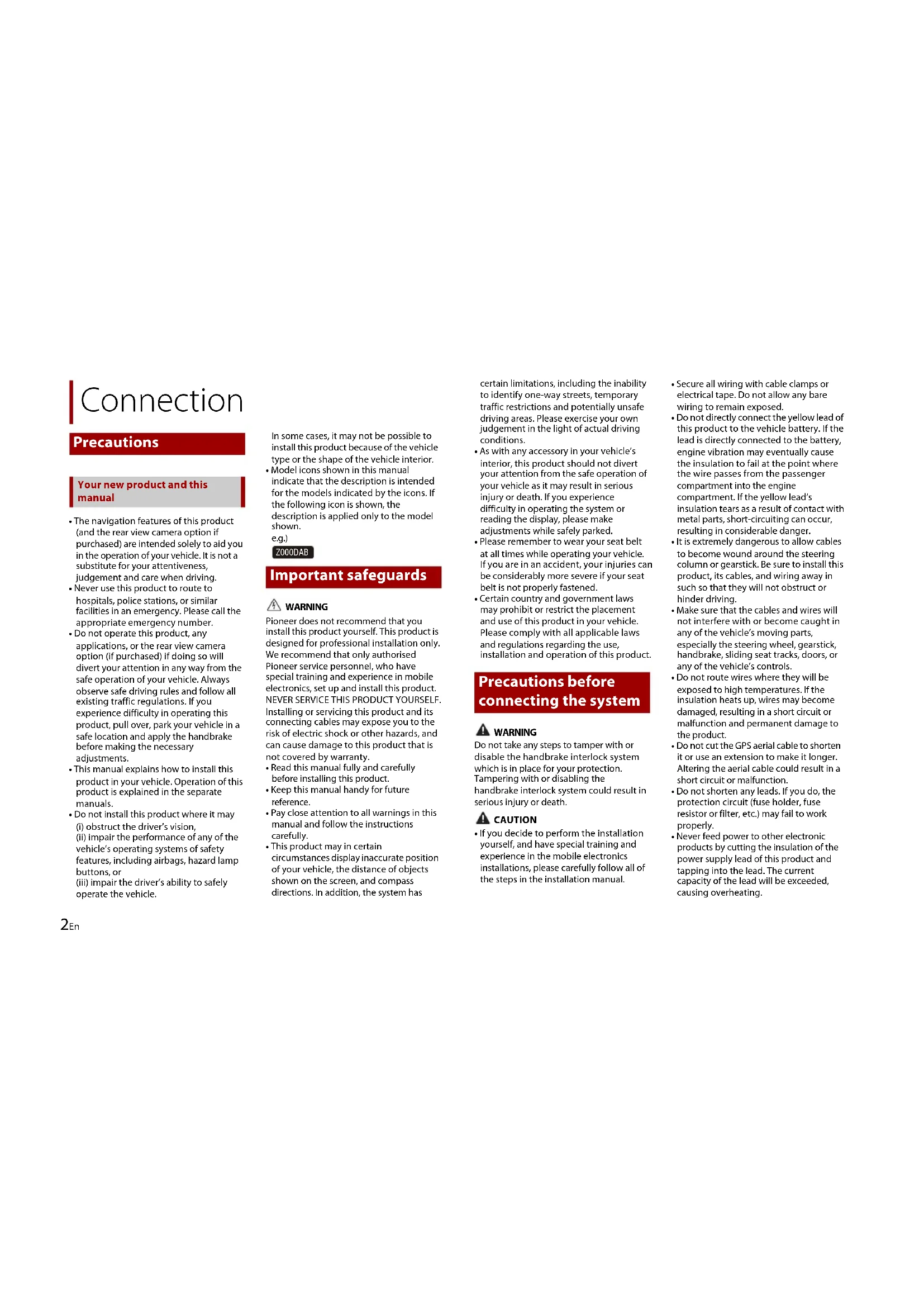
Your new product and this manual
- The navigation features of this product (and the rear view camera option if purchased) are intended solely to aid you in the operation of your vehicle. It is not a substitute for your attentiveness, judgement and care when driving.
- Never use this product to route to hospitals, police stations, or similar facilities in an emergency. Please call the appropriate emergency number.
- Do not operate this product, any applications, or the rear view camera option (if purchased) if doing so will divert your attention in any way from the safe operation of your vehicle. Always observe safe driving rules and follow all existing traffic regulations. If you experience difficulty in operating this product, pull over, park your vehicle in a safe location and apply the handbrake before making the necessary adjustments.
- This manual explains how to install this product in your vehicle. Operation of this product is explained in the separate manuals.
- Do not install this product where it may (i) obstruct the driver's vision, (ii) impair the performance of any of the vehicle's operating systems of safety features, including airbags, hazard lamp buttons, or (iii) impair the driver's ability to safely operate the vehicle.
In some cases, it may not be possible to install this product because of the vehicle type or the shape of the vehicle interior.
- Model icons shown in this manual indicate that the description is intended for the models indicated by the icons. If the following icon is shown, the description is applied only to the model shown.
e.g.)
Z000DAB
Important safeguards
WARNING
Pioneer does not recommend that you install this product yourself. This product is designed for professional installation only. We recommend that only authorised Pioneer service personnel, who have special training and experience in mobile electronics, set up and install this product. NEVER SERVICE THIS PRODUCT YOURSELF. Installing or servicing this product and its connecting cables may expose you to the risk of electric shock or other hazards, and can cause damage to this product that is not covered by warranty. - Read this manual fully and carefully before installing this product. - Keep this manual handy for future reference. - Pay close attention to all warnings in this manual and follow the instructions carefully. - This product may in certain circumstances display inaccurate position of your vehicle, the distance of objects shown on the screen, and compass directions. In addition, the system has
certain limitations, including the inability to identify one-way streets, temporary traffic restrictions and potentially unsafe driving areas. Please exercise your own judgement in the light of actual driving conditions.
- As with any accessory in your vehicle's interior, this product should not divert your attention from the safe operation of your vehicle as it may result in serious injury or death. If you experience difficulty in operating the system or reading the display, please make
- Please remember to wear your seat belt at all times while operating your vehicle. If you are in an accident, your injuries can be considerably more severe if your seat belt is not properly fastened.
- Certain country and government laws may prohibit or restrict the placement and use of this product in your vehicle. Please comply with all applicable laws and regulations regarding the use, installation and operation of this product.
Precautions before connecting the system
WARNING
Do not take any steps to tamper with or disable the handbrake interlock system which is in place for your protection. Tampering with or disabling the handbrake interlock system could result in serious injury or death.
CAUTION
- If you decide to perform the installation yourself, and have special training and experience in the mobile electronics installations, please carefully follow all of the steps in the installation manual.
- Secure all wiring with cable clamps or electrical tape. Do not allow any bare wiring to remain exposed.
- Do not directly connect the yellow lead of this product to the vehicle battery. If the lead is directly connected to the battery, engine vibration may eventually cause the insulation to fail at the point where the wire passes from the passenger compartment into the engine compartment. If the yellow lead's insulation tears as a result of contact with metal parts, short-circuiting can occur, resulting in considerable danger.
- It is extremely dangerous to allow cables to become wound around the steering column or gearstick. Be sure to install this product, its cables, and wiring away in such so that they will not obstruct or hinder driving.
- Make sure that the cables and wires will not interfere with or become caught in any of the vehicle's moving parts, especially the steering wheel, gearstick, handbrake, sliding seat tracks, doors, or any of the vehicle's controls.
- Do not route wires where they will be exposed to high temperatures. If the insulation heats up, wires may become damaged, resulting in a short circuit or malfunction and permanent damage to the product.
- Do not cut the GPS aerial cable to shorten it or use an extension to make it longer. Altering the aerial cable could result in a short circuit or malfunction.
- Do not shorten any leads. If you do, the protection circuit (fuse holder, fuse resistor or filter, etc.) may fail to work properly.
- Never feed power to other electronic products by cutting the insulation of the power supply lead of this product and tapping into the lead. The current capacity of the lead will be exceeded, causing overheating.
Before installing this product
- Use this unit with a 12-volt battery and negative earthing only. Failure to do so may result in a fire or malfunction.
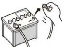
- To avoid shorts in the electrical system, be sure to disconnect the (−) battery cable before installation.
To prevent damage

WARNING
- Use speakers over 50 W (maximum input power) and between 4 Ω to 8 Ω (impedance value). Do not use 1 Ω to 3 Ω speakers for this product.
- The black lead is earth. Please earth this lead separately from the earth of high current products such as power amps. Do not earth more than one product together with the earth from another product. For example, you must separately earth any amp unit away from the earth of this product. Connecting earths together can cause a fire and/or damage the products if their earths became detached.
- When replacing the fuse, be sure to only use a fuse of the rating prescribed on this product.
- When disconnecting a connector, pull the connector itself. Do not pull the lead, as you may pull it out of the connector.
• This product cannot be installed in a vehicle without ACC (accessory) position on the ignition switch.

ACC position

No ACC position
• To avoid short-circuiting, cover the disconnected lead with insulating tape. It is especially important to insulate all unused speaker leads, which if left uncovered may cause a short circuit.
- Attach the connectors of the same colour to the corresponding coloured port, i.e., blue connector to the blue port, black to black, etc.
- For connecting a power amp or other devices to this product, refer to the manual for the product to be connected.
- Since a unique BPTL circuit is employed, do not directly earth the side of the speaker lead or connect the side of another side of the speaker lead together. Be sure to connect the side of the speaker lead to the side of the speaker lead on this product.
- The graphical symbol placed on the product means direct current.
Notice for the blue/white lead
- When the ignition switch is turned on (ACC ON), a control signal is output through the blue/white lead. Connect to an external power amp's system remote control terminal, the auto-aerial relay control terminal, or the aerial booster power control terminal (max. 300 mA 12 V DC). The control signal is output
through the blue/white lead, even if the audio source is switched off.
- Be sure not to use this lead as the power supply lead for the external power amps. Such connection could cause excessive current drain and malfunction.
- Be sure not to use this lead as the power supply lead for the auto-aerial or aerial booster. Such connection could cause excessive current drain and malfunction.

Important
When this product is in [Power OFF] mode, the control signal is also turned off. If [Power OFF] mode is cancelled, the control signal is output again and the aerial is extended with the auto aerial function (if the aerial is being used). Be careful so that the extended aerial does not come into contact with any obstacles.
Rear panel (main terminals)

WARNING
- To avoid the risk of accident and the potential violation of applicable laws, this product should never be used while the vehicle is being driven except for navigation purposes. And, also rear displays should not be in a location where it is a visible distraction to the driver.
- In some countries, the viewing of images on a display inside a vehicle even by persons other than the driver may be illegal. Where such regulations apply they must be obeyed and this product's video source should not be used.
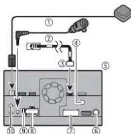
① GPS aerial 3.55 m
② Microphone 3 m
③ Vehicle Bus conversion cable 13 cm*. Refer to the instruction manual for the Vehicle Bus adapter (sold separately).
④ Digital Radio aerial input*
⑤ This product
⑥ Aerial jack
⑦ AV cable IN/OUT
⑧ Power supply
⑨ Fuse (10 A)
⑩ Wired remote input Hard-wired remote control adapter can be connected (sold separately).
*AVIC-Z920DAB/AVIC-Z820DAB/AVIC-Z720DAB/AVIC-Z7210DAB

CAUTION
For improved Digital Radio reception, make sure a Digital Radio aerial with phantom power input (active type) is used. Pioneer recommends using AN-DAB1 or CA-AN-DAB.001 (sold separately). Current consumption of the Digital Radio aerial should be 100 mA or less.
Power cord

WARNING
IMPROPER CONNECTION MAY RESULT IN SERIOUS DAMAGE OR INJURY
INCLUDING ELECTRICAL SHOCK, AND INTERFERENCE WITH THE OPERATION OF THE VEHICLE'S ANTILOCK BRAKING SYSTEM, AUTOMATIC TRANSMISSION AND SPEEDOMETER INDICATION.
CAUTION
It is strongly suggested that the speed pulse wire be connected for accuracy of navigation and better performance.
flowchart
graph TD
    A["①"] --> B["②"]
    B --> C["③"]
    C --> D["④"]
    D --> E["⑤"]
    E --> F["⑥"]
    F --> G["⑦"]
    G --> H["⑧"]
    H --> I["⑨"]
    I --> J["⑩ (5*)"]
    J --> K["⑪ (6*)"]
    K --> L["⑬ 1"]
    L --> M["⑭ 2"]
    M --> N["⑮ 3"]
    N --> O["⑯ 4*"]
    O --> P["⑰ 1*"]
    P --> Q["⑱ 2*"]
    Q --> R["⑲ 3*"]
    R --> S["⑳ 4*"]
    S --> T["⑴ 5*"]
    T --> U["⑵ 6*"]
    U --> V["⑶ 7*"]
    V --> W["⑷ 8*"]
    W --> X["⑧ 9*"]
    X --> Y["⑨ 10*"]
    Y --> Z["⑩ 11*"]
    Z --> AA["⑪ 12*"]
    AA --> AB["⑫ 13*"]
    AB --> AC["⑬ 14*"]
    AC --> AD["⑭ 15*"]
    AD --> AE["⑮ 16*"]
    AE --> AF["⑯ 17*"]
    AF --> AG["⑰ 18*"]
    AG --> AH["⑱ 19*"]
    AH --> AI["㉑ 20*"]
    AI --> AJ["㉒ 21*"]
    AJ --> AK["㉓ 22*"]
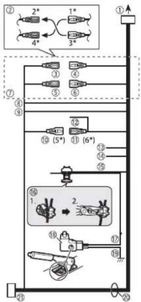
① To power supply
② Depending on the kind of vehicle, the function of 2^ and 4^ may be different. In this case, be sure to connect 1^ to 4^ and 3^ to 2^ .
③ Yellow (2*)
Back-up (or accessory)
④ Yellow (1*)
To terminal supplied with power regardless of ignition switch position.
⑤ Red (4*)
Accessory (or back-up)
⑥ Red (3*)
Connect to terminal controlled by ignition switch (12 V DC).
⑦ Connect leads of the same colour to each other.
⑧ Orange/white
To lighting switch terminal.
⑨ Black (earth)
To vehicle (metal) body.
10 Blue/white (5*)
The pin position of the ISO connector will differ depending on the type of vehicle. Connect 5* and 6* when Pin 5 is an aerial control type. In another type of vehicle, never connect 5* and 6*.
⑪ Blue/white (6*)
Connect to auto-aerial relay control terminal (max. 300 mA 12 V DC).
⑫ Blue/white
Connect to system control terminal of the power amp (max. 300 mA 12 V DC).
⑬ Violet/white
This is connected so that this product can detect whether the vehicle is moving forwards or backwards. Connect the violet/white lead to the lead whose voltage changes when the gearstick is put in reverse. Unless connected, the sensor may not detect your vehicle travelling forwards/backwards properly, and thus the position of your vehicle detected by the sensor may be misaligned from the actual position.
When you use a rear view camera, please make sure to connect this lead. Otherwise you cannot switch to the rear view camera picture.
⑭ Pink (CAR SPEED SIGNAL INPUT)
This product is connected here to detect the distance the vehicle travels. Always connect the vehicle's speed detection circuit. Failure to make this connection will increase errors in the vehicle's location display.
15 Light green
Used to detect the ON/OFF status of the handbrake. This lead must be connected to the power supply side of the handbrake switch.
If this connection is made incorrectly or omitted, certain functions of this product will be unusable.
16 Connection method
Clamp the lead (1) then clamp firmly with needle-nosed pliers (2).
⑰ Power supply side
⑱ Handbrake switch
19 Earth side
20 Speaker leads
White: Front left + or high range left + White/black: Front left - or high range left -
Grey: Front right + or high range right + Grey/black: Front right - or high range right -
Green: Rear left + or middle range left + Green/black: Rear left - or middle range left -
Violet: Rear right + or middle range right +
Violet/black: Rear right – or middle range right –
② ISO connector
In some vehicles, the ISO connector may be divided into two. In this case, be sure to connect to both connectors.
NOTES
• The position of the speed detection circuit and the position of the handbrake switch vary depending on the vehicle model. For details, consult your authorised Pioneer dealer or an installation professional.
- When a subwoofer is connected to this product instead of a rear speaker, change the rear output setting in the initial setting. The subwoofer output of this product is monaural.
- When using a subwoofer of 2 , be sure to connect the subwoofer to the violet and violet/black leads of this unit. Do not connect anything to the green and green/black leads.
Power amp (sold separately)
Important
The speaker leads are not used when this connection is in use.
flowchart
graph TD
    A["Module ①"] --> B["Switch"]
    C["Module ②"] --> D["Switch"]
    E["Module ③"] --> F["Switch"]
    G["Module ④"] --> H["Switch"]
    I["Module ⑤"] --> J["Switch"]
    K["Module ⑥"] --> L["Switch"]
    M["Device ⑦"] --> N["Switch"]
    O["Component ⑧"] --> P["Switch"]
    Q["Component ⑨"] --> R["Switch"]
    S["Component ⑩"] --> T["Switch"]
    U["Component ⑪"] --> V["Switch"]
    W["Component ⑬"] --> X["Switch"]
    Y["Component ⑮"] --> Z["Switch"]
    AA["Component ⑰"] --> AB["Switch"]
    AC["Component ⑪"] --> AD["Switch"]
    AE["Component ⑫"] --> AF["Switch"]
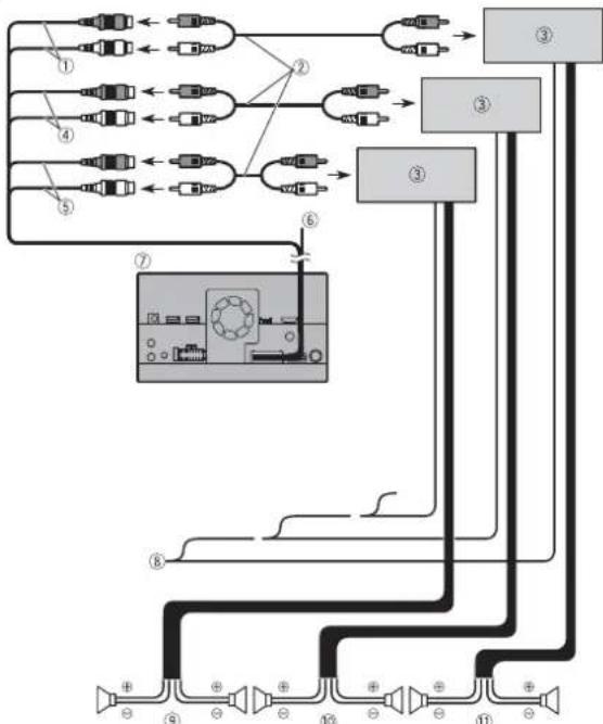
① Subwoofer output (SUBWOOFER OUTPUT) 23 cm (STD)
Low range output (NW)
② RCA cable (sold separately)
③ Power amp
④ Front output (FRONT OUTPUT) 15 cm (STD)
High range output (NW)
⑤ Rear output (REAR OUTPUT) 15 cm (STD)
Middle range output (NW)
⑥ Yellow/black (MUTE)
If you use an equipment with Mute function, wire this lead to the Audio Mute lead on that equipment. If not, keep the Audio Mute lead free of any connections.
⑦ This product
⑧ System remote control
Connect to Blue/white cable (max. 300 mA 12 V DC).
⑨ Rear speaker (STD)
Middle range speaker (NW)
⑩ Front speaker (STD)
High range speaker (NW)
⑪ Subwoofer (STD)
Low range speaker (NW)
NOTES
- Select the appropriate speaker mode between standard mode (STD) and network mode (NW). For details, refer to the Operation Manual.
- Audio source will be set to mute or attenuate, while the following sounds will not be muted or attenuated. For details, refer to Operation Manual.
-Voice guidance of the navigation
-Incoming ring tone and incoming voice of the mobile phone that is connected to this product via Bluetooth wireless technology
iPod/iPhone and smartphone
NOTES
- For details on how to connect an external device using a separately sold cable, refer to the manual for the cable.
- For details concerning the connection, operations and compatibility of the iPhone, refer to the Operation Manual.
- For details concerning the connection and operations of the smartphone, refer to the Operation Manual.
Attaching identification labels to USB cables
Attach identification labels to USB cables before installing this product in a vehicle.
1 Connect USB cables to the USB port 1 and 2 on the rear of this product.
2 Attach the identification labels corresponding to each port to the USB cables as illustrated below. Attach the "Port 1 Apple CarPlay" label to the USB cable connected to the USB port 1. Attach the "Port 2" or "Port 2 Android Auto" label to the USB cable connected to the USB port 2.

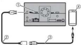
iPod/iPhone
Connecting via the USB port
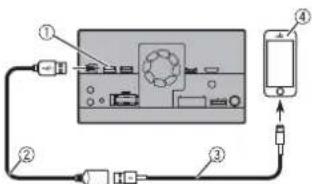
① USB port1
② USB cable 1.5 m
③ USB interface cable for iPod/iPhone (CD-IU52) (sold separately)
④ iPhone
Smartphone (Android™ device)
Connecting via the USB port
flowchart
graph TD
    A["①"] --> B["Central Device"]
    B --> C["Device ④"]
    C --> D["Device ③"]
    D --> E["Device ②"]
    E --> F["Device ③"]
    F --> G["Device ②"]
① USB port2
② USB cable 1.5 m
③ USB - micro USB cable (Type USB A - micro USB B) (supplied with CD-MU200)
④ Smartphone
Camera
When you use the rear view camera, the rear view image is automatically switched from the video by moving the gearstick to REVERSE (R). Camera View mode also allows you to check what is behind you while driving.
WARNING
USE INPUT ONLY FOR REVERSE OR MIRROR IMAGE REAR VIEW CAMERA. OTHER USE MAY RESULT IN INJURY OR DAMAGE.
CAUTION
• The screen image may appear reversed.
- With the rear view camera you can keep an eye on trailers, or back into a tight parking spot. Do not use for entertainment purposes.
- Objects in rear view may appear closer or more distant than in reality.
- The image area of full-screen images displayed while backing or checking the rear of the vehicle may differ slightly.
flowchart
graph TD
    A["Device ①"] --> B["Component ②"]
    B --> C["Component ③"]
    C --> D["Component ④"]
    D --> E["Component ⑤"]
    E --> F["Component ⑥"]
    F --> G["Component ⑦"]
    G --> H["Component ⑧"]
    H --> I["Component ⑨"]
    I --> J["Component ⑩"]
    J --> K["Component ⑪"]
① This product
② Power supply
③ Power cord
④ Violet/white (REVERSE-GEAR SIGNAL INPUT)
⑤ Brown (REAR VIEW CAMERA IN) 23 cm
⑥ Yellow (VIDEO INPUT) 23 cm
⑦ Rear view camera (ND-BC8) (sold separately)
⑧ To video output
⑨ RCA cable (supplied with ND-BC8)
⑩ RCA cable (sold separately)
⑪ View camera (sold separately)
NOTES
- Connect only the rear view camera to brown cable. Do not connect any other equipment.
- Some appropriate settings are required to use rear view cameras. For details, refer to the Operation Manual.
External video component
Using AV input
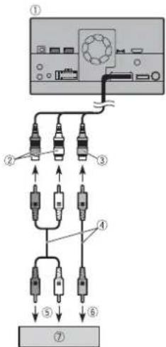
① This product
② Red, white (AUDIO INPUT) 23 cm
③ Yellow (VIDEO INPUT) 23 cm
④ RCA cable (sold separately)
⑤ To audio input
⑥ To video input
⑦ External video component (sold separately)
NOTE
The appropriate setting is required to use the external video component. For details, refer to the Operation Manual.
Using an AUX input
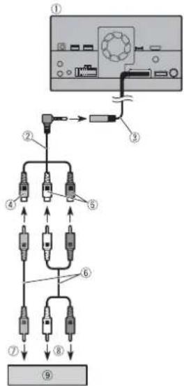
① This product
② Mini-jack AV cable (sold separately)
③ AUX input (AUX IN) 15 cm
④ Yellow
⑤ Red, white
⑥ RCA cables (sold separately)
⑦ To video output
⑧ To audio outputs
⑨ External video component (sold separately)
NOTE
The appropriate setting is required to use the external video component. For details, refer to the Operation Manual.
CAUTION
Be sure to use a mini-jack AV cable (sold separately) for wiring. If you use other cables, the wiring position might differ resulting in disturbed images and sounds.
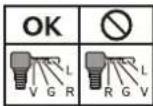
L: Left audio (White)
R: Right audio (Red)
V:Video (Yellow)
G: Earth
Using an HDMI input
Z920DAB
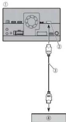
① This product
② HDMI port
③ High Speed HDMI™ Cable (sold
separately)
④ HDMI device (sold separately)
NOTE
When you connect the High Speed HDMI™ Cable, use the lock tie to fix it securely (page 7).
Securing the High Speed HDMI™
Z920DAB
Be sure to fix the High Speed HDMI™ Cable with the lock tie, when you connect the external device with the High Speed HDMI™ Cable.
1 Insert the High Speed HDMI™ Cable into the HDMI port.
2 Wrap the lock tie around the hook above the HDMI port and the High Speed HDMI™ Cable, and then tighten it to secure the High Speed HDMI™ Cable.
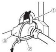
① Hook
② Lock tie
③ High Speed HDMI™ Cable
CAUTION
Do not tighten up the lock tie more than necessary.
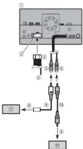
Rear display
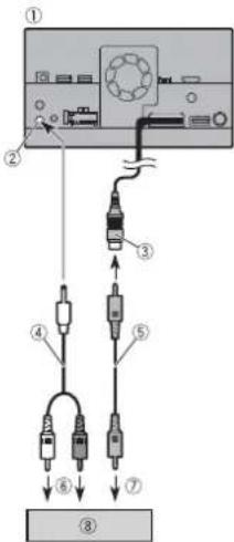
① This product
② Rear audio output (R. AUDIO OUT)
③ Yellow (REAR MONITOR OUTPUT) 30 cm
④ Mini pin plug cable (sold separately)
⑤ RCA cables (sold separately)
⑥ To audio input
⑦ To video input
⑧ Rear display with RCA input jacks (sold separately)
WARNING
NEVER install the rear display in a location that enables the driver to watch the video source while driving.
This product's rear video output is for connection of a display to enable
passengers in the rear seats to watch the video source.
Installation
Precautions before installation
CAUTION
- Never install this product in places where, or in a manner that:
—Could injure the driver or passengers if the vehicle stops suddenly.
- May interfere with the driver's operation of the vehicle, such as on the floor in front of the driver's seat, or close to the steering wheel or gearstick.
- Make sure there is nothing behind the dashboard or panelling when drilling holes in them. Be careful not to damage fuel lines, brake lines, electronic components, communication wires or power cables.
- When using screws, do not allow them to come into contact with any electrical lead. Vibration may damage wires or insulation, leading to a short circuit or other damage to the vehicle.
• To ensure proper installation, be sure to use the supplied parts in the manner specified. If any parts are not supplied with this product, use compatible parts in the manner specified after you have the part compatibility checked by your dealer. If parts other than supplied or compatible ones are used, they may damage internal parts of this product or they may work loose and the product may become detached. - It is extremely dangerous to allow cables to become wound around the steering column or gearstick. Be sure to install this product, its cables, and wiring away in
such so that they will not obstruct or hinder driving.
- Make sure that leads cannot get caught in a door or the sliding mechanism of a seat, resulting in a short circuit.
- Please confirm the proper function of your vehicle's other equipment after installation of this product.
- Do not install this product where it may
(i) obstruct the driver's vision,
(ii) impair the performance of any of the
vehicle's operating systems or safety
features, including airbags, hazard lamp
buttons or
(iii) impair the driver's ability to safely
operate the vehicle.
• Install this product between the driver's seat and front passenger seat so that it will not be hit by the driver or passenger if the vehicle stops quickly. - Never install this product in front of or next to the place in the dashboard, door, or pillar from which one of your vehicle's airbags would deploy. Please refer to your vehicle's owner's manual for reference to the deployment area of the frontal airbags.
- Failure to follow all of these precautions may result in serious injury or death.
To avoid electromagnetic interference
In order to prevent interference, set the following items as far as possible from this product, other cables or leads: • FM, MW/LW aerial and its lead
- DAB aerial and its lead (AVIC-Z920DAB/AVIC-Z820DAB/AVIC-Z720DAB/AVIC-Z7210DAB) - GPS aerial and its lead In addition, you should lay or route each aerial lead as far as possible from other aerial leads. Do not bind, lay or route them together, or cross them. Electromagnetic noise will increase the potential for errors in the vehicle's location display.
Before installing
- Consult with your nearest dealer if installation requires drilling holes or other modifications of the vehicle. - Before making a final installation of this product, temporarily connect the wiring to confirm that the connections are correct and the system works properly.
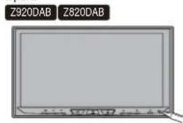
For AVIC-Z920DAB and AVIC-Z820DAB users
Do not install this product in a position where the opening of the LCD panel is obstructed by any obstacles, such as the gearstick. Before installing this product, be sure to leave sufficient space so that the LCD panel does not obstruct the gearstick when it is fully opened. This may cause interference with the gearstick, or a malfunction of the mechanism of this product.
Installation notes
- Do not install this product in places subject to high temperatures or humidity, such as: - Places close to a heater, vent or air conditioner. - Places exposed to direct sunlight, such as on top of the dashboard.
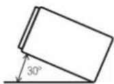
- Places that may be exposed to rain, such as close to the door or on the vehicle's floor. Install this product in an area strong enough to bear its weight. Choose a position where this product can be firmly installed, and install it securely. If this product is not securely installed, the current location of the vehicle cannot be displayed correctly. Install this product horizontally on a surface within 0 to 30 degrees tolerance (within 5 degrees to the left or right). Improper installation of the unit with the surface tilted more than these tolerances increases the potential for errors in the vehicle's location display, and might otherwise cause reduced display performance.
- When installing, to ensure proper heat dispersal when using this unit, make sure you leave ample space behind the rear panel and wrap any loose cables so they are not blocking the vents.
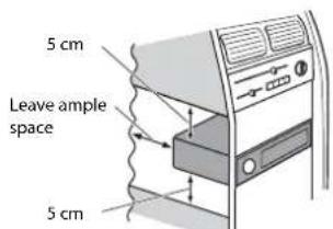
- The cords must not cover the area shown in the figure below. This is necessary to allow the amps and navigation mechanism to dissipate heat.
① Do not cover this area. • The semiconductor laser will be damaged if it overheats, so don't install this product anywhere hot- for instance, near a heater outlet.
Before installing this product
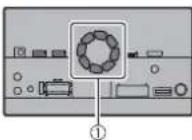
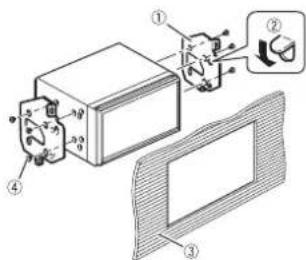
1 Remove the trim ring. Extend top and bottom of the trim ring outwards to remove the trim ring.
① Trim ring
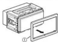
2 Insert the supplied extraction keys into both sides of the unit until they click into place.
3 Pull the unit out of the holder.
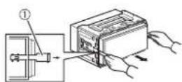
① Extraction key
Installation with the holder
1 Install the holder into the dashboard. 2 Secure the mounting sleeve by using a screwdriver to bend the metal tabs (90°) into place.
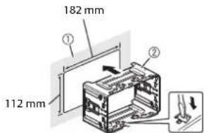
① Dashboard ② Holder
3 Install this product into the holder.
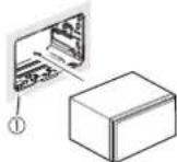
① Dashboard 4 Attach the trim ring.
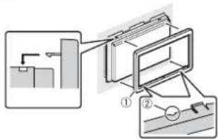
① Trim ring
② Groove
Attach the trim ring with the side with a groove facing downward.
Installation using the screw holes on the side of this product
1 Fastening this product to the factory radio-mounting bracket.
Position this product so that its screw holes are aligned with the screw holes of the bracket, and tighten the screws at three locations on each side.
Use either the truss head screws or flush surface screws, depending on the shape of the bracket's screw holes.
① Factory radio-mounting bracket
② If the pawl interferes with installation, you may bend it down out of the way.
③ Dashboard or console
④ Truss head screw or flush surface screw
Be sure to use the screws supplied with this product.
Installing the GPS aerial
CAUTION
Do not cut the GPS aerial lead to shorten it or use an extension to make it longer. Altering the aerial cable could result in a short circuit or malfunction and permanent damage to this product.
Installation notes
- The aerial should be installed on a level surface where radio waves will be blocked as little as possible. Radio waves cannot be received by the aerial if reception from the satellite is blocked.
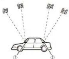
① Dashboard
② Rear shelf
- When installing the GPS aerial inside the vehicle, be sure to use the metal sheet provided with your system. If this is not used, the reception sensitivity will be poor.
- Do not cut the accessory metal sheet. This would reduce the sensitivity of the GPS aerial.
• Take care not to pull the aerial lead when removing the GPS aerial. The lead may become detached.
- Do not paint the GPS aerial, as this may affect its performance.
When installing the aerial inside the vehicle (on the dashboard or rear shelf)

WARNING
Do not install the GPS aerial over any sensors or vents on the dashboard of the vehicle, as doing so may interfere with the proper functioning of such sensors or vents and may compromise the ability of the metal sheet under the GPS aerial to properly and securely affix to the dashboard.
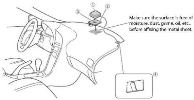
① GPS aerial
② Metal sheet
Peel off the protective sheet on the rear.
③ Double-sided tape
④ Clamps
Use clamps to secure the lead where necessary inside the vehicle.
NOTES
- Affix the metal sheet on the surface as level as possible where the GPS aerial faces the window.
- Affix the GPS aerial on the metal sheet using the double-sided tape.
- The metal sheet contains a strong adhesive which may leave a mark on the surface if it is removed.
- When attaching the metal sheet, do not cut it into small pieces.
- Some models use window glass that does not allow signals from GPS satellites to pass through. On such models, install the GPS aerial on the outside of the vehicle.
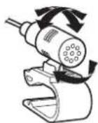
Installing the microphone
- Install the microphone in a place where its direction and distance from the driver make it easiest to pick up the driver's voice.
- Be sure to turn off (ACC OFF) the product before connecting the microphone.
- Depending on the vehicle model, the microphone cable length may be too short when you mount the microphone on the sun visor. In such cases, install the microphone on the steering column.
Mounting on the sun visor
1 Fit the microphone lead into the groove.
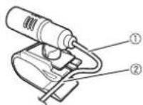
① Microphone lead ② Groove
2 Attach the microphone clip to the sun visor.
① Microphone clip
② Clamps
Use separately sold clamps to secure the lead where necessary inside the vehicle.
Install the microphone on the sun visor when it is in the up position. It cannot recognise the driver's voice if the sun visor is in the down position.
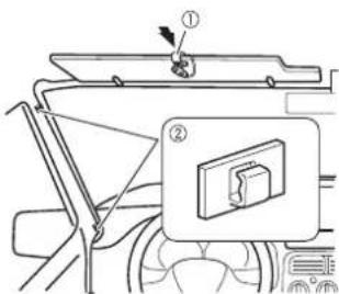
Installation on the steering column
1 Detach the microphone base from the microphone clip by sliding the microphone base while pressing the tab.
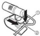
① Tab
② Microphone base
2 Mount the microphone on the steering column.
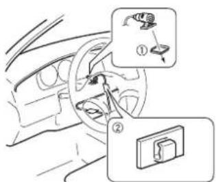
① Double-sided tape
② Clamps
Use separately sold clamps to secure the lead where necessary inside the vehicle.
NOTE
Install the microphone on the steering column, keeping it away from the steering wheel.
Adjusting the microphone angle
The microphone angle can be adjusted.
After installation
After installing this product
1 Reconnect the negative (-) terminal of the vehicle's battery.
First, double-check that all connections are correct and that this product is installed correctly. Reassemble all vehicle components that you previously removed. Then reconnect the negative (-) cable to the negative (-) terminal of the battery.
2 Start the engine.
3 Press the RESET button.
Press the RESET button on this product with a pointed object such as the tip of a pen.
- Some of the settings and recorded contents will not be reset.
4 Change the settings as desired.
- For details concerning operations, refer to Operation Manual.
5 Drive down an unobstructed road until the GPS starts receiving the signal normally.
NOTE
After installing this product, be sure to check at a safe place that the vehicle is performing normally.

Connexion
Précautions
Panneau arrière (bornes principales)
ATTENTION
1 Retirez la garniture.
① Garniture
② Rainure
① PortaUSB 1
② Cavo USB da 1,5 m
③ Cavo interfaccia USB per iPod/iPhone (CD-IU52) (venduto separatamente)
④ iPhone
① Porta USB 2
② Cavo USB da 1,5 m
③ Cavo USB - micro USB (tipo USB A - micro USB B) (fornito con CD-MU200)
④ Smartphone
Videocamera
① Ghiera
② Scanalatura
① Puerto USB 2
② Cable USB de 1,5 m
③ Cable USB - micro USB (Tipo USB A - micro USB B) (suministrado con el CD-MU200)
④ Smartphone
Cámara
① Anillo embellecedor
② Ranura
natural_image
Illustration of a generic electronic device with a screen and control panel (no text or symbols visible)① Armaturenbrett
② Hutablage
① Mikrofon-Clip
② Kabelklemmen
① Dit product
L: Audio links (wit)
R: Audio rechts
(rood)
V:Video (geel)
G:Aarde
① Dashboard
② Hoedenplank
① Microfoonklem
② Klemmen
28-8, Honkomagome 2-chome, Bunkyo-ku,
Tokyo 113-0021, Japan
PIONEER EUROPE NV
Haven 1087, Keetberglaan 1, B-9120 Melsele, Belgium/Belgique
TEL: (0) 3/570.05.11
PIONEER ELECTRONICS (USA) INC.
P.O. Box 1540, Long Beach, California 90801-1540, U.S.A.
TEL: (800) 421-1404
© 2019 PIONEER CORPORATION. All rights reserved.