
RM-1000BP - Remote control SONY - Free user manual and instructions
Find the device manual for free RM-1000BP SONY in PDF.
| Product type | Wired remote control for camcorder |
| Brand | Sony |
| Model | RM-1000BP |
| Dimensions (W x H x D) | 158 x 70 x 181 mm |
| Weight (main unit) | 402 g |
| Power supply | Via camcorder (LANC terminal) |
| Operating temperature | 0 °C to 40 °C |
| Operating humidity | Less than 80% |
| Storage temperature | -20 °C to +60 °C |
| Main functions | Zoom, focus, iris, white balance, shutter, gain, picture profile, assignable switches, menu control |
| Package contents | Remote control, accessory cable 1 m, accessory cable 10 m, carrying case, mounting plate, hand strap |
| Safety | Do not expose to rain or moisture; avoid shocks and liquid spills; do not overtighten mounting screws |
| Maintenance and cleaning | Clean with a soft, dry cloth. Do not use solvents. |
| Cleaning | Soft dry cloth |
Frequently Asked Questions - RM-1000BP SONY
User questions about RM-1000BP SONY
0 question about this device. Answer the ones you know or ask your own.
Ask a new question about this device
Download the instructions for your Remote control in PDF format for free! Find your manual RM-1000BP - SONY and take your electronic device back in hand. On this page are published all the documents necessary for the use of your device. RM-1000BP by SONY.
USER MANUAL RM-1000BP SONY
Operating Instructions GB
Mode d'emploi FR
natural_image
Technical line drawing of a mechanical clamp or bracket assembly (no text or symbols)操作上のご注意
To reduce fire or shock hazard, do not expose the unit to rain or moisture.
For the Customers in the U. S. A.
This device complies with Part 15 of the FCC Rules. Operation is subject to the following two conditions:
(1) this device may not cause harmful interference, and
(2) this device must accept any interference received, including interference that may cause undesired operation.
CAUTION
You are cautioned that any changes or modifications not expressly approved in this manual could void your authority to operate this equipment.
Note:
This equipment has been tested and found to comply with the limits for a Class B digital device, pursuant to Part 15 of the FCC Rules.
These limits are designed to provide reasonable protection against harmful interference in a residential installation. This equipment generates, uses, and can radiate radio frequency energy and, if not installed and used in accordance with the instructions, may cause harmful interference to radio communications. However, there is no guarantee that interference will not occur in a particular installation. If this equipment does cause harmful interference to radio or television reception, which can be determined by turning the equipment off and on, the user is encouraged to try to correct the interference by one or more of the following measures:
– Reorient or relocate the receiving antenna.
- Increase the separation between the equipment and receiver.
- Connect the equipment into an outlet on a circuit different from that to which the receiver is connected.
- Consult the dealer or an experienced radio/TV technician for help.
For the Customers in Canada
This Class B digital apparatus complies with Canadian ICES-003.
For the Customers in Europe
Disposal of Waste Electrical and Electronic Equipment for business use (Applicable in the European Union and other European countries with separate collection systems)

natural_image
Symbol of a trash bin crossed out by two diagonal lines (no text or numbers present)
This symbol on the product or on its packaging indicates that this product shall not be treated as household waste. Instead it shall be handed over to the applicable take-back scheme for the recycling of electrical and electronic equipment. By ensuring this product is disposed of correctly, you will help prevent potential negative consequences for the environment and human health, which could otherwise be caused by inappropriate waste handling of this product. The recycling of materials will help to conserve natural resources. For more detailed information about recycling of this product, please contact your local Sony office or visit Sony Europe's web site for business customers:
http://www.sonybiz.net/environment
This product with the CE marking complies with the EMC Directive issued by the Commission of the European Community.
Compliance with this directive implies conformity to the following European standards:
• EN55103-1 :Electromagnetic Interference (Emission)
• EN55103-2 :Electromagnetic Susceptibility (Immunity)
This product is intended for use in the following Electromagnetic Environment(s):
E1 (residential), E2 (commercial and light industrial), E3 (urban outdoors) and E4 (controlled EMC environment ex. TV studio).
Notice for the customers in the countries applying EU Directives
The manufacturer of this product is Sony Corporation, 1-7-1 Konan Minato-ku Tokyo, 108-0075 Japan. The Authorized Representative for EMC and product safety is Sony Deutschland GmbH, Hedelfinger Strasse 61, 70327 Stuttgart, Germany. For any service or guarantee matters please refer to the addresses given in separate service or guarantee documents.
Table of Contents
Cautions 5
Notes on Use....6
Features 6
Preparation before Use....7
Identifying the Parts....8
Separate HOLD Setting....16
Specifications 18
Cautions
Refer to this manual and the operating instructions provided with your video camera for further information as well.
- Be sure not to drop this unit or spill liquid on it.
- Do not leave this unit in direct sunlight, near a heater, or in locations with high humidity.
- Insert and remove the remote plug in a straight manner. Inserting or removing the remote plug by force may cause this unit to damage.
- Do not overly tighten the fixing plate. Doing so may damage this unit.
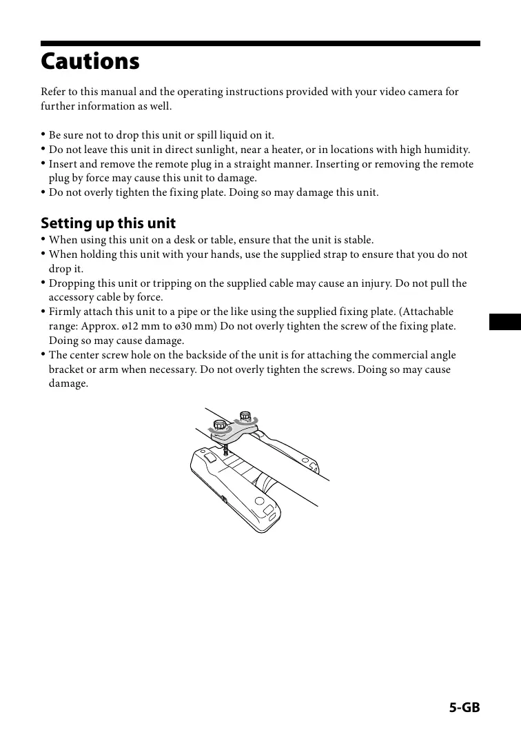
Setting up this unit
- When using this unit on a desk or table, ensure that the unit is stable.
- When holding this unit with your hands, use the supplied strap to ensure that you do not drop it.
- Dropping this unit or tripping on the supplied cable may cause an injury. Do not pull the accessory cable by force.
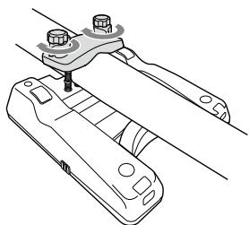
- Firmly attach this unit to a pipe or the like using the supplied fixing plate. (Attachable range: Approx. 12 mm to 30 mm) Do not overly tighten the screw of the fixing plate. Doing so may cause damage.
- The center screw hole on the backside of the unit is for attaching the commercial angle bracket or arm when necessary. Do not overly tighten the screws. Doing so may cause damage.
natural_image
Technical line drawing of a mechanical clamp or bracket assembly (no text or symbols)Notes on Use
- This unit cannot perform two or more remote-control operations at the same time with the system. Operate one at a time.
- When the video camera is set to auto-adjust recording, some control keys of the video camera cannot be operated by this unit.
- Check the result of the operation with this unit on the LCD screen of the video camera or monitor output screen etc.
- This unit can change the video camera's setting even if they have been set by changing the position of the switch on the video camera.
When disconnecting the cable or the power of the video camera is cycled, the video camera settings will change to those of the switch position on the video camera.
Example of the appropriate switch:
Slide switch, lever switch etc. (H/M/L of GAIN, PRESET/A/B of WHT BAL etc.)
- The control keys on this unit operate in almost the same way as the corresponding control keys on the video camera.
(Operation with the FOCUS/IRIS dial and ZOOM lever on this unit and operation with the FOCUS/IRIS dial and ZOOM lever on the video camera are very similar but not exactly the same.)
For details on the operation settings, refer to the operating instructions provided with your video camera.
Features
- The RM-1000BP is a Remote Commander for making images by video engineers.
- This unit can be connected to the video camera using the LANC 📊 terminal with the accessory cable. (For details, see p. 7.)
- Using this unit enables the remote operation of the MENU key and other control keys on the video camera.
- This unit makes operations smooth because of the arrangement of the IRIS dial, the FOCUS dial and ZOOM lever.
- By using the ZOOM DIRECTION switch and ZOOM SPEED switch, this unit can operate the wide variations of zoom operation with the ZOOM lever.
Preparation before Use
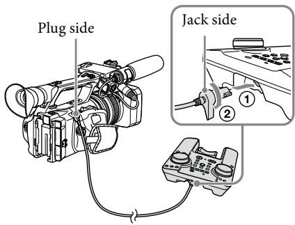
Connecting this unit to the video camera
1 Place this unit at a stable place. Check that the power of the video camera is set to "OFF."
2 Turn downward the lever portion of the accessory cable jack side. Insert it straight into the terminal on the back side of this unit and rotate the accessory cable jack 90 degrees in a clockwise direction to lock it.
3 Connect the plug side of the accessory cable to the video camera.
- If this unit is separated from the video camera, use the accessory cable (10 m).
- Do not connect any cable to this unit other than the accessory cable. Do not connect the accessory cable 1m and 10m .
Setting the video camera to recording status
For details, refer to the operating instructions provided with your video camera.
Set the power of the video camera to "ON" and cancel the auto-adjust recording status\*.
The POWER LED and REC LED of this unit light in red and then change to green. Then POWER LED lights in green.
* The operating switch that sets and cancels the auto-adjust recording status of the video camera varies depending on the video camera. (AUTO LOCK switch, AUTO/MANUAL switch etc.)
- Cancel the auto-adjust recording status of the video camera. Check that each function can be adjusted manually. When the video camera is in the auto-adjust recording status, the POWER LED blinks slowly in green.
- When the remaining tape or battery power is low, the REC LED will blink in red.
Identifying the Parts
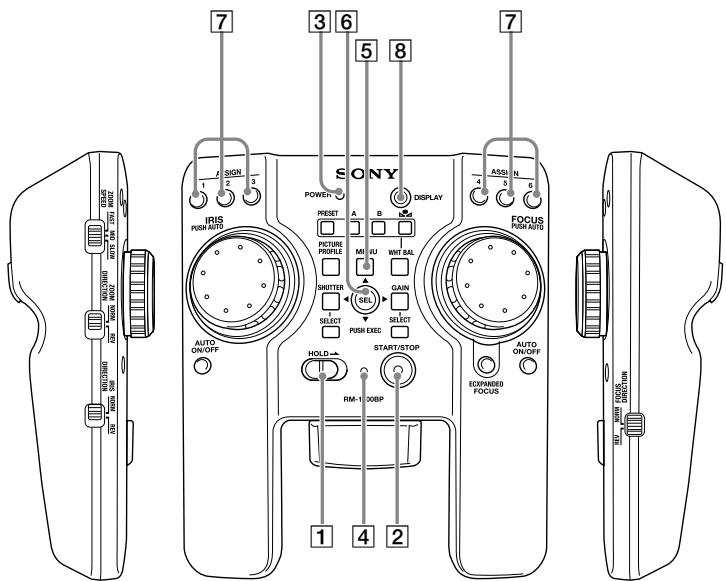
1 HOLD switch
HOLD is set or canceled by the position of this switch.
ON (right position): This unit is set to HOLD. This unit cannot operate the video camera.
OFF (left position): HOLD setting of this unit is cancelled.
You can select the control key that can be operated when this unit is set to HOLD. For details, see “Separate HOLD Setting” (p. 16).
2 START/STOP key
Recording starts by pressing this key.
To stop recording, press the START/STOP key again.
3 POWER LED
The status of this unit is indicated.
Lit (green): This unit is connected to the video camera correctly.
Blinking slowly (green): The video camera is in the auto-adjust recording status.
Blinking rapidly (green): The pressed control key is in HOLD status.
4 REC LED
The recording status of the video camera is indicated.
Lit (red): The video camera is in the recording status.
Blinking slowly (red): The remaining capacity of the tape or remaining battery power is low.
Blinking rapidly (red): The tape or battery power will run out soon.
Blinking (green): The video camera is in the preparation status between the times when the START/STOP button is pressed and when the recording starts correctly.
Extinguished: Recording is stopped.
5 MENU key
The MENU screen appears by pressing this key.
To hide the MENU screen, press this key again.
6 SEL/PUSH EXEC lever
The selected item or number can be changed on the MENU screen or other menu setting screen by moving this lever from right to left or up and down.
To confirm or enter the selected item, press the center of this lever.
- For details, refer to the operating instructions provided with your video camera.
- Depending on the video camera, moving this lever from right to left may not be possible.
7 ASSIGN key
The functions assigned to the ASSIGN keys on the video camera are applied by pressing these keys.
- For details on settings, refer to the operating instructions provided with your video camera.
8 DISPLAY key
The OSD (ON SCREEN DISPLAY) on the screen is switched by pressing this key.
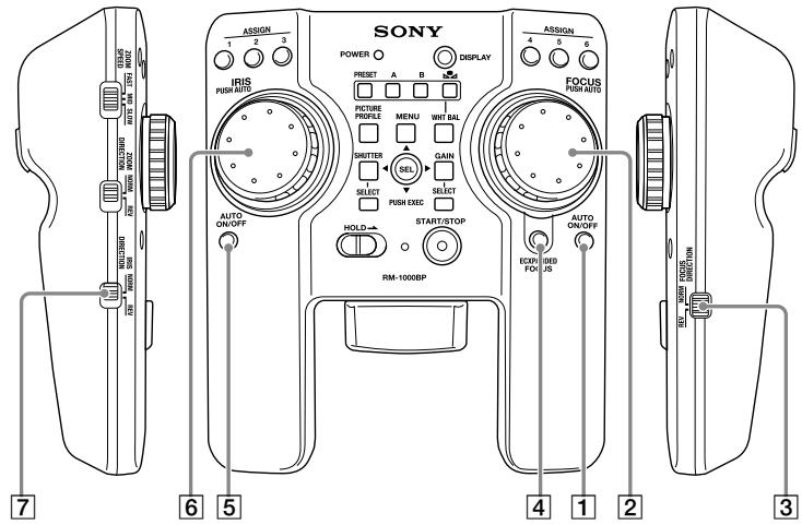
Focus adjustment
1 FOCUS AUTO ON/OFF key
The auto focus adjustment is set or canceled by pressing this key.
2 FOCUS dial
Rotate this dial to adjust the focus.
Depending on the speed of rotating the dial, the quantity of the focus adjustment will vary.
If the dial is rotated faster, the focus will change to the NEAR side/FAR side faster.
To adjust the focus automatically, press and hold the center of the dial. (PUSH AUTO FOCUS function)
During PUSH AUTO FOCUS, if you leave your hand from the dial, auto focus adjustment will be stopped.
- Depending on the video camera, the quantity of the focus adjustment varies by the quantity and speed of rotating the dial.
3 FOCUS DIRECTION switch
The direction of rotating the FOCUS dial can be changed by the position of this switch.
NORM: When rotating the FOCUS dial in the clockwise direction, the focus adjusts closer. When rotating the FOCUS dial in the counterclockwise direction, the focus adjusts further.
REV: When rotating the FOCUS dial in the clockwise direction, the focus adjusts further. When rotating the FOCUS dial in the counterclockwise direction, the focus adjusts closer.
4 EXPANDED FOCUS key
The image on the screen is magnified by pressing this key.
To return to the original size, press the key again.
Notes
When using the video camera with a replacement lens, set the focus ring to the electronic control status if you are using the supplied lens. If you are using a lens other than the one that was supplied, this unit may not operate the focus of the video camera.
Iris adjustment
5 IRIS AUTO ON/OFF key
The auto iris adjustment is set or canceled by pressing this key.
6 IRIS dial
Iris is adjusted by rotating this dial.
Depending on the speed of rotating the dial, the quantity of the iris adjustment will vary. If the dial is rotated faster, the iris will change to the OPEN side/CLOSE side faster.
To adjust the iris automatically, press and hold the center of the dial. (PUSH AUTO IRIS function)
During PUSH AUTO IRIS, if you leave your hand from the dial, auto iris adjustment will be stopped.
- Depending on the video camera, the quantity of the iris adjustment varies by the quantity and speed of rotating the dial.
7 IRIS DIRECTION switch
The direction of rotating the IRIS dial can be changed by the position of this switch.
NORM: When rotating the IRIS dial in the clockwise direction, the aperture is opened. When rotating the IRIS dial in the counterclockwise direction, the aperture is closed.
REV: When rotating the IRIS dial in the clockwise direction, the aperture is closed. When rotating the IRIS dial in the counterclockwise direction, the aperture is opened.
Notes
When using the video camera with a replacement lens, set the iris switch of the lens to “auto adjustment (AUTO)”.
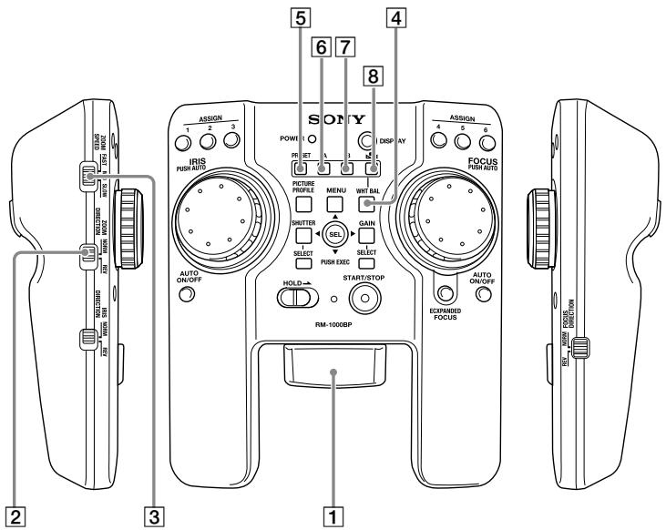
ZOOM
If the video camera has the ZOOM switch, set it to [SERVO] or [REMOTE] etc.
1 ZOOM lever
Zoom is adjusted by rotating this lever.
2 ZOOM DIRECTION switch
The direction of rotating the ZOOM lever can be changed by the position of this switch.
NORM: When rotating the ZOOM lever to the right, the subject appears closer (telephoto). When rotating the ZOOM lever to the left, the subject appears further (wide-angle).
REV: When rotating the ZOOM lever to the right, the subject appears further (wide-angle). When rotating the ZOOM lever to the left, the subject appears closer (telephoto).
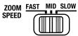
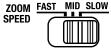
3 ZOOM SPEED switch
The quantity of the zoom speed when rotating the ZOOM lever can be changed by the position of this switch.
SLOW: Regardless of the ZOOM lever's rotating quantity, the video camera zooms at the slowest speed constantly.
MID: Depending on the ZOOM lever's rotating quantity, the video camera zooms faster. (4 stages)
FAST: Depending on the ZOOM lever's rotating quantity, the video camera zooms even faster. (8 stages)
White balance adjustment
4 WHT BAL key
The white balance is set to manual adjustment by pressing this key and the white balance setting set on the video camera is applied.
To return to the auto white balance adjustment, press this key again.
- For details on settings, refer to the operating instructions provided with your video camera.
5 PRESET key
PRESET is applied by pressing this key. For details on changing or switching the settings, refer to the operating instructions provided with your video camera.
6 A key
The value of the white balance stored in the ▲A (memory A) is applied by pressing this key.
7 B key
The value of the white balance stored in the ⚪B (memory B) is applied by pressing this key.
8 ▲ key ((one push) WHT BAL)
When the white balance is set to □A or □B, the value of the white balance stored in □A or □B is applied by pressing this key.
- For details on settings, refer to the operating instructions provided with your video camera.
Notes
When using a video camera that has a slide switch or lever switch, the white balance setting (PRESET, A, B etc.) can be changed by changing the position of the switch or lever. If the accessory cable is disconnected or the power of the video camera is cycled, the video camera setting will be changed to that of the position of the switch on the video camera.
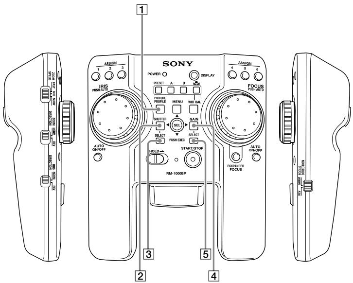
Picture profile setting
1 PICTURE PROFILE key
The picture profile setting screen is applied by pressing this key.
To hide the setting screen, press this key again.
- For details on settings, refer to the operating instructions provided with your video camera.
Shutter speed adjustment
2 SHUTTER key
The auto shutter adjustment is cancelled and the shutter setting or value of the shutter speed set on the video camera is applied by pressing this key.
- Depending on the video camera, the shutter setting change mode is applied.
3 SELECT key
The shutter setting applied by pressing the SHUTTER key can be changed by pressing this key.
Notes
Depending on the video camera, the SELECT key may not be available. To make settings or to change the shutter speed value, refer to the operating instructions provided with your video camera.
Gain adjustment
4 GAIN key
The gain setting set on the video camera is applied by pressing this key.
5 SELECT key
The gain mode applied by pressing the GAIN key can be changed.
Notes
When using a video camera that has a slide switch or lever switch, the gain setting can be changed by changing the position of the switch or lever. The video camera setting changes to that of the position of the switch on the video camera, if the accessory cable is disconnected or the video camera power is cycled.
Separate HOLD Setting
You can set the each control key to the key that is set to HOLD or the key that can be operated when the HOLD switch is set to ON.
The default setting is that all operations are set to HOLD.
Setting to the separate HOLD setting status
1 Slide the HOLD switch to ON.
This unit is set to the HOLD mode.
2 While you press and hold the DISPLAY key, press and hold the SEL/PUSH EXEC lever to the left for two seconds or more.
This unit enters the HOLD key editable mode.
By changing the position of the ZOOM SPEED switch, you can select the mode among the following three modes.
| ZOOM SPEED switch position | Mode | Function | Mode display |
 | HOLD key select mode | In this mode, the operation of that key toggles between usable/prohibited when set to HOLD. | POWER LED lights (red). |
 | HOLD key check and store mode | In this mode, whether the control key can be operated when this unit is set to HOLD is displayed on the REC LED by pressing the key.Press and hold the SEL/PUSH EXEC lever for two seconds or more to store the setting set in the HOLD key select mode. | POWER LED lights (orange). |
 | HOLD key initialize mode | In this mode, press and hold the SEL/PUSH EXEC lever for two seconds or more to initialize the setting of the control key. | POWER LED blinks (red). |
Separate HOLD setting of the control key
1 Slide the ZOOM SPEED switch to FAST to set to the HOLD key select mode.
2 Set the desired control key to the key that can be operated when this unit is set to HOLD by operating the key.
While you press and hold the key, the REC LED displays the status of the key.
Lit (red): The key cannot be operated when this unit is set to HOLD.
Lit (green): The key can be operated when this unit is set to HOLD.
3 When you have finished making separate HOLD settings for the desired keys, slide the ZOOM SPEED switch to MID to set to the HOLD key check and store mode.
4 Press the each key to check the status of the separate HOLD setting.
While you press and hold the key, the REC LED displays the status of the key.
Lit (red): The key cannot be operated when this unit is set to HOLD.
Lit (green): The key can be operated when this unit is set to HOLD.
5 Press and hold the SEL/PUSH EXEC lever for two or more to store the setting selected in the HOLD key select mode.
The separate HOLD setting is effective. The mode returns to the normal HOLD status.
- If you do not operate the key for 15 seconds or more, the mode returns to the normal HOLD status.
- The separate HOLD setting is not effective until the setting is stored. If the mode is returns to the normal HOLD status when you are setting the each key, the previous setting will be disabled.
Initializing the separate HOLD settings of the control key
1 Slide the ZOOM SPEED switch to SLOW to set to the HOLD key initialize mode.
2 Press and hold the SEL/PUSH EXEC lever for two seconds or more.
The settings of the keys return to the default setting.
Specifications
Functions:
HOLD switch, START/STOP key, MENU key, SEL/PUSH EXEC lever, ASSIGN key, DISPLAY key
Focus
FOCUS dial, FOCUS DIRECTION switch, FOCUS AUTO ON/OFF key, EXPANDED FOCUS key
Iris
IRIS dial, IRIS DIRECTION switch, IRIS AUTO ON/OFF key
Zoom
ZOOM lever, ZOOM DIRECTION switch, ZOOM SPEED switch
White balance
WHT BAL key, PRESET key, A key, B key, ▲▲ key
Picture profile
PICTURE PROFILE key
Gain
GAIN key, SELECT key
Shutter
SHUTTER key, SELECT key
Dimensions:
Approx. 158 × 70 × 181 mm (6 1/4 × 2 7/8 × 7 1/4 in.) (w/h/d)
Mass:
Approx. 402 g (14.2 oz) (Main body only)
Operating environment:
Operating temperature: 0 °C to 40 °C ( 32 °F to 104 °F )
Operating humidity: less than 80%
Storing temperature:
-20^ to +60^ (-4^ to +140^)
Included items:
Remote Commander (1)
Accessory cord (1 m) (1)
Accessory cord (10 m) (1)
Storage case (1)
Fixing plate (1)
Hand strap (1)
Set of printed documentation
Design and specifications are subject to change without notice.
Français
AVERTISSEMENT
natural_image
Symbol of a trash bin crossed out by two diagonal lines (no text or numbers present)
natural_image
Technical line drawing of a mechanical assembly with no visible text or symbolsnatural_image
Symbol of a trash bin crossed out by two diagonal lines (no text or numbers present)
natural_image
Technical line drawing of a mechanical assembly with no visible text or symbolsNotas sobre el uso
Selector IRIS, interruptor IRIS DIRECTION, tecla IRIS AUTO ON/OFF
Zoom
Palanca ZOOM, interruptor ZOOM DIRECTION, interruptor ZOOM SPEED
Balance de blancos
natural_image
Technical line drawing of a mechanical clamp or bracket assembly (no text or symbols)使用须知
8 键 (one push) WHT BAL)
Printed on 70% or more recycled paper
using VOC (Volatile Organic
Compound)-free vegetable oil based ink.