
DCM5001 - Cd player/recorder DENON - Free user manual and instructions
Find the device manual for free DCM5001 DENON in PDF.
| Product Type | CD changer player (100 discs) |
| Brand | Denon |
| Model | DCM5001 |
| Disc capacity | 100 CDs (vertical magazine changer) |
| Daisy chain connection | Up to 5 units (600 CDs maximum) with DCM-5000 main unit |
| Output zones | Dual zone (zone 1 and zone 2) with separate signals possible |
| Special functions | Random play, continuous play, cross fade, CD-TEXT compatibility, HDCD and AL24 processing (via DCM-5000) |
| Analog audio outputs | 2 channels (L/R), level 2.0 V |
| Digital output | Coaxial (0.5 Vp-p, 75 Ω) |
| Frequency response | 2 – 20,000 Hz |
| Signal-to-noise ratio | 100 dB |
| Harmonic distortion | 0.008% (1 kHz) |
| Power supply | AC 120 V, 60 Hz (North American models) |
| Power consumption | 42 W |
| Dimensions (W × H × D) | 434 × 243 × 474.5 mm |
| Weight | 16.2 kg |
| Maintenance and cleaning | Clean CDs with a soft, dry cloth. Do not use benzene or thinner. |
| Safety | Disconnect power before moving. Avoid high temperatures. Do not insert objects into the unit. |
| Included accessories | User manual, warranty, connection cables (audio, coaxial, control) |
Frequently Asked Questions - DCM5001 DENON
User questions about DCM5001 DENON
0 question about this device. Answer the ones you know or ask your own.
Ask a new question about this device
Download the instructions for your Cd player/recorder in PDF format for free! Find your manual DCM5001 - DENON and take your electronic device back in hand. On this page are published all the documents necessary for the use of your device. DCM5001 by DENON.
USER MANUAL DCM5001 DENON
TO PREVENT FIRE OR SHOCK HAZARD, DO NOT EXPOSE THIS APPLIANCE TO RAIN OR MOISTURE.
CAUTION:
- Handle the power supply cord carefully
Do not damage or deform the power supply cord. If it is damaged or deformed, it may cause electric shock or malfunction when used. When removing from wall outlet, be sure to remove by holding the plug attachment and not by pulling the cord.
- Do not open the top cover
In order to prevent electric shock, do not open the top cover. If problems occur, contact your DENON dealer.
- Do not place anything inside
Do not place metal objects or spill liquid inside the CD player. Electric shock or malfunction may result.
Please, record and retain the Model name and serial number of your set shown on the rating label.
Model No. DCM-5001 Serial No.
CAUTION: TO REDUCE THE RISK OF ELECTRIC SHOCK, DO NOT REMOVE COVER (OR BACK). NO USER-SERVICEABLE PARTS INSIDE. REFER SERVICING TO QUALIFIED SERVICE PERSONNEL.

The lightning flash with arrowhead symbol, within an equilateral triangle, is intended to alert the user to the presence of uninsulated "dangerous voltage" within the product's enclosure that may be of sufficient magnitude to constitute a risk of electric shock to persons.

The exclamation point within an equilateral triangle is intended to alert the user to the presence of important operating and maintenance (servicing) instructions in the literature accompanying the appliance.
FOR U.S.A. & CANADA MODEL ONLY
CAUTION
TO PREVENT ELECTRIC SHOCK DO NOT USE THIS (POLARIZED) PLUG WITH AN EXTENSION CORD, RECEPTACLE OR OTHER OUTLET UNLESS THE BLADES CAN BE FULLY INSERTED TO PREVENT BLADE EXPOSURE.
POUR LES MODELES AMERICAINS ET CANADIENS UNIQUEMENT
ATTENTION
POUR PREVENIR LES CHOCSELECTRIQUES NE PAS UTILISER CETTE FICHE POLARISEE AVEC UN PROLONGATEUR UNE PRISE DE COURANT OU UNE AUTRE SORTIE DE COURANT, SAUF SI LES LAMES PEUVENT ETRE INSEREES A FOND SANS EN LAISSE AUCUNE PARTIE A DECOUVERT.
NOTE:
This CD player uses the semiconductor laser. To allow you to enjoy music at a stable operation, it is recommended to use this in a room of 5^ (41^) 35^ (95^)
LABELS (for U.S.A. model only)
CERTIFICATION
THIS PRODUCT COMPLIES WITH DHHS RULES 21 CFR SUBCHAPTER APPLICABLE AT DATE OF MANUFACTURE.
CAUTION:
USE OF CONTROLS OR ADJUSTMENTS OR REFORMANCE OF PROCEDURES OTHER THAN THOSE SPECIFIED HEREIN MAY RESULT IN HAZARDOUS RADIATION EXPOSURE.
THE COMPACT DISC PLAYER SHOULD NOT BE ADJUSTED OR REPAIRED BY ANYONE EXCEPT PROPERLY QUALIFIED SERVICE PERSONNEL.
This device complies with Part 15 of the FCC Rules. Operation is subject to the following two conditions: (1) This device may not cause harmful interference, and (2) this device must accept any interference received, including interference that may cause undesired operation.
This Class B digital apparatus meets all requirements of the Canadian Interference-Causing Equipment Regulations.
Use compact discs that include the

CD's with special shapes (heart-shaped CD's, octagonal CD's etc.) cannot be played on this set.
Attempting to do so may damage the set. Do not use such CD's.
- Read Instructions - All the safety and operating instructions should be read before the appliance is operated.
- Retain Instructions - The safety and operating instructions should be retained for future reference.
- Heed Warning - All warnings on the appliance and in the operating instructions should be adhered to.
- Following Instructions - All operating and use instructions should be followed.
- Water and Moisture - The appliance should not be used near water - for example, near a bathtub, washbowl, kitchen sink, laundry tub, in a wet basement, or near a swimming pool, and the like.
- Carts and Stands - The appliance should be used only with a cart or stand that is recommended by the manufacturer.
6A. An appliance and cart combination should be moved with care. Quick stops, excessive force, and uneven surfaces may cause the appliance and cart combination to overturn

- Wall or Ceiling Mounting - The appliance should be mounted to a wall or ceiling only as recommended by the manufacturer.
- Ventilation - The appliance should be situated so that its location or position does not interfere with its proper ventilation. For example, the appliance should not be situated on a bed, sofa, rug, or similar surface that may block the ventilation openings; or, placed in a built-in installation, such as a bookcase or cabinet that may impede the flow of air through the ventilation openings.
- Heat - The appliance should be situated away from heat sources such as radiators, heat registers, stoves, or other appliances (including amplifiers) that produce heat.
- Power Sources - The appliance should be connected to a power supply only of the type described in the operating instructions or as marked on the appliance.
-
Grounding or Polarization - Precautions should be taken so that the grounding or polarization means of an appliance is not defeated.
-
Power-Cord Protection - Power-supply cords should be routed so that they are not likely to be walked on or pinched by items placed upon or against them, paying particular attention to cords at plugs, convenience receptacles, and the point where they exit from the appliance.
- Cleaning - The appliance should be cleaned only as recommended by the manufacturer.
- Power Lines - An outdoor antenna should be located away from power lines.
- Outdoor Antenna Grounding - If an outside antenna is connected to the receiver, be sure the antenna system is grounded so as to provide some protection against voltage surges and built-up static charges. Article 810 of the National Electrical Code, ANSI/NFPA 70, provides information with regard to proper grounding of the mast and supporting structure, grounding of the lead-in wire to an antenna-discharge unit, size of grounding conductors, location of antenna-discharge unit, connection to grounding electrodes, and requirements for the grounding electrode. See Figure A.
- Nonuse Periods - The power cord of the appliance should be unplugged from the outlet when left unused for a long period of time.
- Object and Liquid Entry - Care should be taken so that objects do not fall and liquids are not spilled into the enclosure through openings.
- Damage Requiring Service - The appliance should be serviced by qualified service personnel when:
A. The power-supply cord or the plug has been damaged; or
B. Objects have fallen, or liquid has been spilled into the appliance; or
C. The appliance has been exposed to rain; or
D. The appliance does not appear to operate normally or exhibits a marked change in performance; or
E. The appliance has been dropped, or the enclosure damaged.
- Servicing - The user should not attempt to service the appliance beyond that described in the operating instructions. All other servicing should be referred to qualified service personnel.

NOTE ON USE / HINWEISE ZUM GEBRAUCH/OBSERVATIONS RELATIVES A L'UTILISATION NOTE SULL'USO / NOTAS SOBRE EL USO / ALVORENS TE GEBRIKEN / OBSERVERA OBSERVACOs QUANTO AO USO
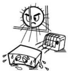
- Avoid high temperatures.
Allow for sufficient heat dispersion when installed on a rack.
- Handle the power cord carefully.
Hold the plug when unplugging the cord.

* (For sets with ventilation holes)
- Do not obstruct the ventilation holes.
Die Belfuftungsoffnungen durren nicht verdeckt werden. - Ne pas obstruer les trouss d'aération.
Non coprite i for di ventilazione. - No obstruya los crificios de ventilacion.
De ventilatieopeningen mogen niet worden beiblockeerd. - Tapp inte till ventilationsöppningarna.
- Não obstrua os orificios de ventilação.
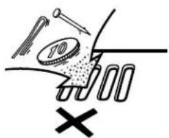
Do not let foreign objects in the set.
Keine fremden Gegenstände in das Gerätkommen lessen.
- No pas laisser des objets étrangers dans l'appareil.
E' importante che nessun oggett e inserito all'interno dell'unita.
- No deje objetos extraños dentro del equipo.
- Laat geen vreemde voorwerpen in dit apparaat vaallen.
So till att frammande foremal into frangir in i apparaten.
- Não deixe objetos estranhos no aparecido.

- Do not let insecticides, benzene, and thinner come in contact with the set.
- Lassen Sie das Gerald nicht mit Insektiziden, Benzin oder Verdunnungsmitteln in Berührung kommt.
- Ne pasmettre en contact des insecticides, du benzene et un diluent avec l'appareil.
- Assicuratevvi che l'unità non venga in contatto con insetticidi, benzo o solvent.
- No permita el contacto de insecticides, gasolina y diluyentes con el equipo.
- Laat geen insetkenverdelgende middelen, benzine of vertverdunner met dit apparaat in contactiert koren.
- Se till att inte inseteksmedel på spraybru, bensen och thinner kommer i kontakt med apparatens höje.
- Não permitta que insetecidas, benzina e dissolveente entrem em contacto com o aparelho.
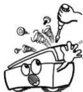
- Never disassemble or modify the set in any way.
Versuchen Sie nimels das Gerat auseinander zu erhönen oder auf jegliche Art zu verändern. - Ne jamais démonter ou modifier l'appareil d'une manière ou d'une autre.
Non smontate mai, ne modifie l'unita in nessun mode. - Nunca désarme o modifie e equipo de minunaforma.
- Noot oil apparaat demonteren of op andere wize modifieren.
Ta inte isar apparaten och forsok inte bygga om den. - Nunca desmonte ou modifique o'aquarelode alamage forma.
Thank you for purchasing the DENON compact disc player. Read the Operating Instructions thoroughly, and operate this player properly.
TABLE OF CONTENTS
1 MAIN FEATURES 5
2 BEFORE USING 5
3 CAUTIONS ON INSTALLATION 6
4 CAUTIONS DURING USE 6
5 INSTALLATION 7,8
6 STAND-ALONE PLAYBACK 9~11
DAISY CHAIN PLAYBACK. 11~14
8 COMPACT DISCS 14
9 TROUBLESHOOTING 15
10 SPECIFICATIONS 15
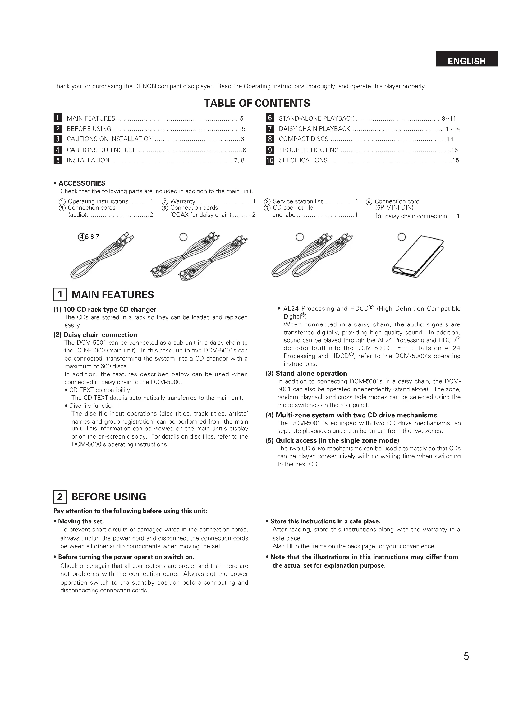
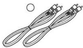
- ACCESSORIES
Check that the following parts are included in addition to the main unit.
① Operating instructions 1
(5) Connection cords
② Warranty. 1
6 Connection cords 10
③ Service station list
CD booklet file
④ Connection cord
(5P MINI-DIN)
for daisy chain connection....1


1 MAIN FEATURES
(1) 100-CD rack type CD changer
The CDs are stored in a rack so they can be loaded and replaced easily.
(2) Daisy chain connection
The DCM-5001 can be connected as a sub unit in a daisy chain to the DCM-5000 (main unit). In this case, up to five DCM-5001s can be connected, transforming the system into a CD changer with a maximum of 600 discs.
In addition, the features described below can be used when connected in daisy chain to the DCM-5000.
- CD-TEXT compatibility
The CD-TEXT data is automatically transferred to the main unit.
Disc file function
The disc file input operations (disc titles, track titles, artists' names and group registration) can be performed from the main unit. This information can be viewed on the main unit's display or on the on-screen display. For details on disc files, refer to the DCM-5000's operating instructions.
- AL24 Processing and HDCD® (High Definition Compatible Digital®)
When connected in a daisy chain, the audio signals are transferred digitally, providing high quality sound. In addition, sound can be played through the AL24 Processing and HDCD decoder built into the DCM-5000. For details on AL24 Processing and HDCD, refer to the DCM-5000's operating instructions.
(3) Stand-alone operation
In addition to connecting DCM-5001s in a daisy chain, the DCM-5001 can also be operated independently (stand alone). The zone, random playback and cross fade modes can be selected using the mode switches on the rear panel.
(4) Multi-zone system with two CD drive mechanisms
The DCM-5001 is equipped with two CD drive mechanisms, so separate playback signals can be output from the two zones.
(5) Quick access (in the single zone mode)
The two CD drive mechanisms can be used alternately so that CDs can be played consecutively with no waiting time when switching to the next CD.
2 BEFORE USING
Pay attention to the following before using this unit:
- Moving the set.
To prevent short circuits or damaged wires in the connection cords, always unplug the power cord and disconnect the connection cords between all other audio components when moving the set.
- Before turning the power operation switch on.
Check once again that all connections are proper and that there are not problems with the connection cords. Always set the power operation switch to the standby position before connecting and disconnecting connection cords.
- Store this instructions in a safe place.
After reading, store this instructions along with the warranty in a safe place.
Also fill in the items on the back page for your convenience.
- Note that the illustrations in this instructions may differ from the actual set for explanation purpose.
3 CAUTIONS ON INSTALLATION
The CD player uses a microcomputer for controlling internal electronic circuits. In the event that the player is used while a near-by tuner or TV is turned on, although unlikely, interference could occur either in the sound from the tuner or the picture of the TV. To avoid this, please take the following precautions.
- Keep the CD player as far away from the tuner or TV set as possible.
- Keep the power cord and connecting cords of the CD player separate from the antenna wires of the tuner and TV.
- Interference is particular likely to occur when an indoor antenna or a 300/ ohms feeder cable is used. Thus, use of an outdoor antenna and 75/ ohms coaxial cable is strongly recommended.

300Ω/ohms feeder cable
75 Ω/ohms coaxial cable
Be sure to install the player on a flat surface. Setting it at a slant may result in malfunction or damage.


4 CAUTIONS DURING USE
- This compact disc player is capable of playing discs which have the mark at right.
- During track selection, during search and when the player sustains a strong impact, the disc's rotational speed changes greatly, causing a small noise to be emitted. This is not a malfunction of the player.
- If the CD player is operated while an FM or AM broadcast is being received, there may be noise in the FM or AM reception. Please switch the power to the CD player off at such times.
- The DCM-5000 has a broad dynamic range. Please exercise caution when turning up the volume on the amplifier in cases when the playback volume is low. If the volume is turned up too high, it could damage the speakers.

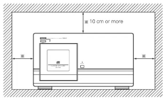
For heat dispersal, leave at least 10cm of space between the top, back and sides of this unit and wall or other components.

- Do not use any discs but exclusive audio discs with this CD player.
- Placing this player or its connection cords near a TV or other audio device could cause a humming sound to be emitted. If this occurs, relocate the player or reroute the connection cords.
- Be sure to remove the disc from the player before moving it. The discs could be damaged if left in the player while it is being moved.
- Do not move the player from a cold place to a warm place suddenly. If the player is cold when brought into a warm room, condensation could form, preventing proper operation of the player. If condensation does form on the player when it is brought into a warm room, wait at least 30 minutes before use.
5 INSTALLATION
Removing the Shipping Screws
The internal mechanisms are locked in place with shipping screws to protect them from shocks and vibrations. Be sure to remove the shipping screws (three) before using the player.
1 Turn the three shipping screws on section A of the rear panel counterclockwise and remove them.
2 Fasten the removed shipping screws in the holes in section B.
* The shipping screws and rubber washers will be needed when shipping the player in the future, so be sure to fasten them to the holes in section B so as not to lose them.

[When moving the player]
When shipping the player, be sure to protect the internal mechanisms from shocks and vibrations using the procedure described below.
1 Remove all the CDs from the disc rack following the procedure described under "Loading CDs" (page 8).
2 Close the front cover.
3 Press the power operation switch ON/STANDBY) to turn the power off.
4 Press the power operation switch (ON/STANDBY) while pressing in the DOOR OPEN button to turn the power on. Press and hold in the DOOR OPEN button. The DOOR OPEN LED starts flashing (green).
When the DOOR OPEN LED stops flashing (remaining lit), release the button, remove the three shipping screws from section B of the rear panel, put them in the holes in section A, then tighten them to lock the internal mechanism in place.
6 Press the power operation switch (ON/STANDBY) to turn the power off.
![DENON DCM5001 - [When moving the player] - 1](/content/2026/03/506467/images/513041cff688583116512a4df5f1f8a426378384a5553a88b26db22b7f660911.jpg)
![DENON DCM5001 - [When moving the player] - 2](/content/2026/03/506467/images/b115890e3c97da283732296e44745688854dfa27d944878d4cf8d1646381bb16.jpg)
Loading CDs
1
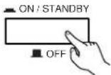
Press the power operation switch ON/STANDBY) to turn on the power.
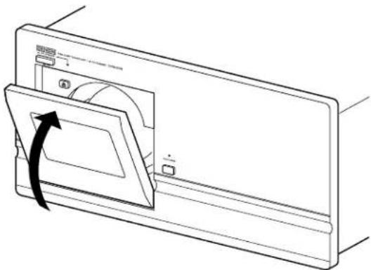
2

Press the DOOR OPEN button to open the front cover.
The DOOR OPEN button is operational about 10~20 seconds after the power is turned on.
- The DOOR OPEN LED flashes (red). Once the cover is open, the LED stops flashing remaining lit (red).
3
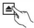
Press the eject button.
The disc rack unlocks and pops out a little.
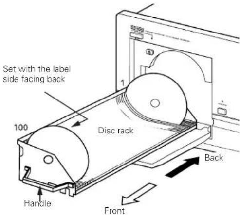
4
Grasp the disc rack's handle and pull the disc rack toward you.
5
Insert the CDs in the slits with the desired numbers.
- Set the discs with the label side facing back.
6
Grasp the disc rack's handle and push the disc rack in until it locks (until you hear a click).
7
Close the front cover.
- Push the front cover in until it locks (until you hear a click). The DOOR OPEN LED turns off.
- If no discs are loaded in the set, the DOOR OPEN LED lights (green).
NOTES:
- Never put your hands or other objects inside the set when the front cover is open. Doing so may result in injury or damage.
- Never place anything other than CDs on the disc rack. Doing so may result in damage.
- If you drop a disc into the player or drop a disc from the disc rack inside the player, disconnect the power immediately and contact your store of purchase.
- This model is for 12cm CD. Do not insert an 8cm CD nor 8cm CD with an adaptor. It damages both the player and the disc.


Booklet file
The liner notes or lyric cards for up to 100 CDs can be stored in the included booklet file.
We recommend attaching number stickers with the same numbers as the slits in which the discs are loaded to the booklet file's pockets.
600 number seals are provided for use should extra units be installed in a daisy chain.

Removing CDs
Following the procedure under "Loading CDs" to draw out the disc rack, then remove the CDs.
After removing the CDs, push the disc rack all the way in and close the front cover.
- Always remove all the CDs when moving the player. If discs are loaded, shocks or vibrations may cause scratches or damage to the CDs or the internal mechanisms.
- Before proceeding with connections or disconnections of cable and power cords, be sure to turn all system components off.
- Ensure that all cables are connected properly to the L (left) and R (right) jacks.
- Insert plugs fully into the terminals.
- Connect the output jacks to the amplifier CD, AUX or TAPE PLAY input jacks.
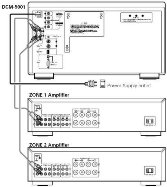
Connecting the Analog Output Jacks
Connect one end of the connection cord supplied with the CD player to the output terminals, left (L) and right (R) of the CD player, and the other end to the CD, AUX, or TAPE PLAY input terminals, left (L) and right (R), of the amplifier.
Connecting the Digital Output Jack (COAXIAL)
Use a 75 Ω/ohms coaxial pin cord to connect the digital output jack (DIGITAL COAX OUT) of the DCM-5001 to the digital input jack (COAXIAL) on a digital processor or D/A unit.
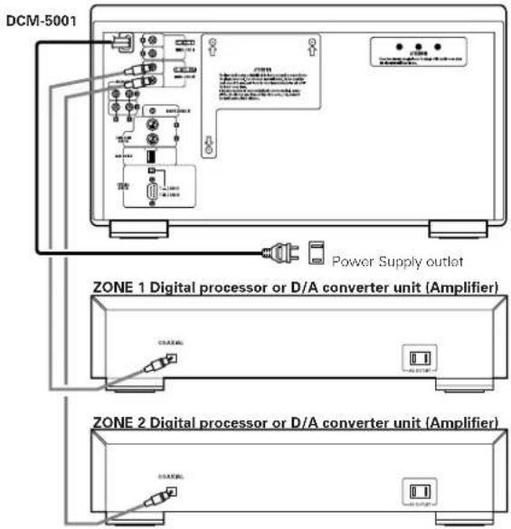
NOTE:
When the single zone mode is selected, no digital data is output from the ZONE 2 side.
Other Connections
The DCM-5001 is provided with computer and remote control interface ports, for compatibility with external remote control solutions offered by third party vendors. Contact your dealer or installation consultant for advice if you are considering the purchase of an external control system.
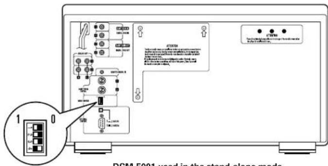
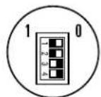
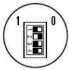
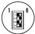
MODE SWITCH settings
When using the DCM-5001 in the stand alone mode, first set the play mode. Select the desired play mode using the mode switches on the rear panel, as shown on the table below.
| Switch setting | Mode | ||||||
| SW1 | SW2 | SW3 | SW4 | Zone mode | Continuous/Random | Cross fade | Play mode |
| 1 | 1 | 1 | 0 | SINGLE | CONTINUE | — | Continuous playback in the single zone mode. |
| 1 | 1 | 0 | 1 | SINGLE | RANDOM | ON | Random, cross fade playback in the single zone mode. |
| 1 | 1 | 0 | 0 | SINGLE | RANDOM | OFF | Random playback in the single zone mode. |
| 1 | 0 | 1 | 1 | MULTI | CONTINUE | — | Continuous playback in the multi zone mode. |
| 1 | 0 | 0 | 1 | MULTI | RANDOM | — | Random playback in the multi zone mode. |

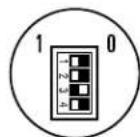
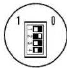
Switch and function settings
Single zone output Continuous play (Cross fade disabled)
Single zone output Random play Cross fade
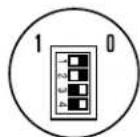
Single zone output
Random play
No cross fade
Multi-zone output Continuous play (Cross fade disabled)

Multi-zone output Random play (Cross fade disabled)
Play modes
Zone modes
The DCM-5001 has two sets of outputs (zone 1 and zone 2), and different playback signals can be output from each zone when in the multi zone mode.
Select the zone mode before starting playback.
SINGLE: The same signals are output from zone 1 and zone 2.
MULTI: Separate playback signals are output from zone 1 and zone 2.
Continuous and random modes
Continuous mode: All tracks of all discs are played in order starting from the lowest disc number.
In the multi-zone mode, disc 1 in zone 1 and disc 2 in zone 2 are played first, after which the next appropriate discs are selected and played in order.
Random mode: All the CDs are played in random order. One track is selected at random from each of the CDs.
Cross fade playback
The cross fade play function can only be used in the single zone mode.
The cross fade mode allows you to play tracks continuously without breaks in the sound by fading in and out when switching from playback on one disc to a track on the next disc.
Cross fade playback is possible, as described on the table below.
Random mode:
Cross fade playback is performed between tracks on discs selected at random (one track per disc).
Order of playback: Disc 3, Tr 5 Disc 18, Tr 1 Disc 56 Tr 3 Disc 29, Tr 4 ...
NOTE:
-
No signals are output from the digital outputs when the cross fade mode is selected.
-
In all play modes, playback starts over from the beginning of the first disc once the last disc is played. (The repeat play mode is set.)
Playback
- Once connection to the amplifier, disc setting and setting of the play mode with the mode switches are completed, once press the POWER OPERATION switch to turn off, and press the POWER OPERATION switch again to turn on.
The indicator lights (green) if there is no disc. Load a disc.

Playback begins in the set mode.
Turn off the POWER OPERATION switch to stop playback.
- When the DCM-5001 is used in the stand-alone mode, there is no standby mode for the POWER OPERATION switch. The power can only be set to ON (■) or OFF (■).
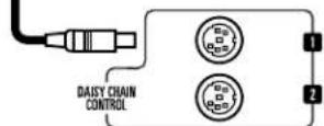
DAISY CHAIN PLAYBACK
Connections (outline)

To connect in daisy chain, connect as shown on the diagram above. For details, refer to the following page.
Daisy chain control signals: Connect the connector cords (5-pin cords, included) from the last sub unit in the chain to the next higher one, and so on.
- Digital audio signals: These are connected in the same way as the daisy chain control signals. Be sure to connect both connector cords (included) between the units, whether you select the single zone mode or the multi zone mode.
* Digital output from the main unit (DCM-5000) with the daisy chain.
Each unit in the daisy chain has its own digital output signals based on the each system clock and the main unit transfers its digital data to outside equipments.
So it may cause the digital-unlock for a while and may result a pause in the sound or a spike noise when switching to another unit during the daisy chain operation. It depends on the receiving equipments (digital amp, D/A converter etc.) respectively.
In this case, do not connect the digital output to other equipments.
(We recommended to use the Audio signal output)
Connections (detailed)
(Connections when using a DCM-5000 as the main unit)
- When using DCM-5001s as sub units, up to five DCM-5001s can be connected (resulting in a 600-disc CD changer).

For connections of the DCM-5000 to the amplifier and other components, refer to the DCM-5000's operating instructions.
DCM-5000 (main unit)
DCM-5001 (first)
DCM-5001 (second)
- To avoid the hum, noise and other troubles during operation, please connect the supplied connector cords.
DCM-5001 (third)
DCM-5001 (fourth)
DCM-5001 (fifth)
Cautions on daisy chain connections
Daisy chain connection (COAX)
- Connect the input and output jacks to the output and input jacks (respectively) with the same numbers.

* Be sure to connect both (1, 2) cords.
Daisy chain connection (control)
The cord can be connected to either the 1 or 2 jack.

Mode switch setting with daisy chain connection
Set the mode switches of the different components as described on the tables below.
Main unit (DCM-5000) setting
| Switch setting | Setting (ID No.) | Disc no. assignment | |||
| SW1 | SW2 | SW3 | SW4 | ||
| 1 | 0 | 0 | 0 | Main unit of a daisy chain | 1 ~ 100 |
Sub unit (DCM-5001) setting
| Switch setting | Setting (ID No.) | Disc no. assignment | |||
| SW1 | SW2 | SW3 | SW4 | ||
| 0 | 0 | 0 | 1 | 1st sub unit in daisy chain | 101 ~ 200 |
| 0 | 0 | 1 | 0 | 2nd sub unit in daisy chain | 201 ~ 300 |
| 0 | 0 | 1 | 1 | 3rd sub unit in daisy chain | 301 ~ 400 |
| 0 | 1 | 0 | 0 | 4th sub unit in daisy chain | 401 ~ 500 |
| 0 | 1 | 0 | 1 | 5th sub unit in daisy chain | 501 ~ 600 |
- Be sure to make the above settings. Be sure to set the DCM-5000 as the main unit. The first sub unit (the sub unit connected after the main unit) must be set to "0001". It cannot be set as the second or third sub unit. It is also not possible to skip numbers in the middle. The sub unit connected after the first sub unit must be set to the ID number for the second sub unit.
- If the mode switches are set wrong, the system cannot be operated normally.
Example: For the 3rd sub unit
DCM-5000 DCM-5001 DCM-5001 DCM-5001

"1000" "0001" "0010" "0011"
Playback
- Check the connections between all the components and the ID number settings of the different units (set with the mode switches), then turn on the power.
- Do not turn on the power switch of the main unit before turning on the power of the sub units. (It is necessary for the main unit to recognize the other unit.)
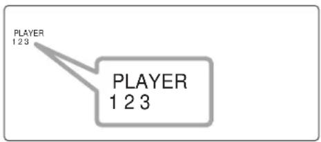
The numbers of the currently connected sub units appear in the "PLAYER" area of the DCM-5000's fluorescent display, indicating that the sub units are recognized as sub units.
Example: When a total of three units are connected (one DCM-5000 and two DCM-5001s): "1", "2" and "3" light.
- Once the above is completed, the DCM-5001s can be operated in the same way as the DCM-5000 using the keys on the DCM-5000's front panel or the remote control unit. (For details, refer to the DCM-5000's operating instructions.)
The system can be used as a CD changer with a maximum of 600 discs, and various operations can be performed (disc files, group playback, etc.).
- Before turn on the daisy chain system, be sure to check that the each unit's door is closed.
If you turn on the power with any unit open, its unit and the lower sub units can not be recognized as the part of the daisy chain system. - If you once open the door of one unit (main or sub unit) in the system, the daisy chain system stops its operation. Close the doors in order to restart the operation of the system.
- If you once turn off one of the unit (main unit or other sub unit) during operation, the system cannot be operated properly. So in this case, once turn off all the units and turn on the power of all the units again.
- Do not turn off the sub units during playback in any case. It will produce the noise from the audio output due to unusual condition of the system.
- If the connection cords (daisy chain control cords or digital audio cords for daisy chain) are not connected properly. Error message "Error 080 000" or "Error 1000 000" ( is a number code) appears on the display under circumstances.
If this happens, once turn off all the units of the system and check that the each connection cords are properly connected or not.
After correct the connection, turn on the power of the each unit again.
(If the problem persists, contact your store of purchase)
- About the error code in daisy chain
If the error code appears on the DCM-5000's display in the daisy chain system, the player No. that caused the error is also showed on the display.
Example: Error in the 1st sub unit.

DCM-5000 (Main unit) display
In this case, open the door of the displayed player depends on the error type. (For details, please refer to the DCM-5000's instruction manual.)
Close the door after check the disc, etc.
Once turn off the power of all units and turn on the daisy chain system again.
8 COMPACT DISCS
1. Cautions in Handling Compact discs
- Do not get fingerprints, oil, dirt or other substances on the compact disc. If the disc becomes dirty, wipe it off with a dry, soft cloth.
- Do not clean compact discs with benzene, paint thinner, water, record spray, anti-static agent, silicon cloth or similar substances.
- Take particular care to prevent scratches to the back side of the compact disc when removing it from the case and when inserting it in its case.
- Do not bend compact discs.
- Do not apply to compact discs.
-
Do not attempt to enlarge the center hole of the disc.
-
Do not write on the label (printed) side of the disc with a ball point pen or pencil.
- Bringing a CD into a warm room from a cold place could cause moisture to condense on the disc surface. Do not attempt to dry the disc with a hair dryer, etc.
2. Storage of Compact Discs
- To prevent dust, scratches, deformation, etc., be sure to store compact discs in their case.
-
Do not store compact discs in the following locations.
-
Places where direct sunlight strikes for long periods of time.
- Places with a high humidity or a lot of dust.
- Places reached by heat from a heater or similar appliance.
9 TROUBLESHOOTING
If a problem should arise, first check the following.
1.Are all connections correct?
- Have you operated the player according to the Operating Instructions?
If this unit is not operating properly, check the items listed in the table below. Should the problem persist, there may be a malfunction.
Disconnect the power immediately and contact your store of purchase.
| Symptom Cause Measures | Page | ||
| LED not lit when power switch set to on. | • Power cord not plugged in securely. • Check the insertion of the power cord plug. • Turn the power on with the remote control unit after turning the POWER switch on. | 9— | |
| Playback does not start in the stand alone mode. | • There are no discs in the disc rack. • Is the disc dirty or scratched? • The mode switches are not properly set. | 8 14 10 | |
| There is no sound, or it is distorted. | • Is the output cord properly connected to the amplifier? • Have the amplifier controls been set correctly? | 9 • Adjust the amplifier's controls. | |
| A specific position of the disc will not play. | • Is the disc dirty or scratched? • Wipe the dirt off the disc or replace the disc. 14 | ||
| No data is output from the digital output jack. | • Is the pin cord properly connected? • Check the connections. 9 | ||
| CD cannot be played or no sound is produced when connected in daisy chain. | • Is the pin cord (Digital out, in) properly connected? • Is the daisy chain control code properly connected? • The mode switches are not properly set. | 12 • Check the mode switch setting. |
10 SPECIFICATIONS
ANALOG
No. of Channels: 2 Channels
Frequency Response: 2 20,000~Hz
Wow & Flutter: Below measurable limit: ( ±0.001 % W.peak)
Output Level: 2.0V
Signal-to-noise Ratio: 100 dB
Harmonic Distortion: 0.008% (1 kHz)
DIGITAL
Output: COAXIAL (0.5 V P-P 75 Ω/ohms)
DISCS Compact Disc format
GENERAL CHARACTERISTICS
Power Supply: AC 120 V, 60 Hz (for North America model)
Power Consumption: 42 W
Dimensions: 434 (W) x 243 (H) x 474.5 (D) mm (17-3/32") x (9-9/16") x (18-43/64")
Weight: 16.2 kg (35 lbs 11 oz)
HDCD® and High Definition Compatible Digital® are registered trademarks of Pacific Microsonics, Inc.
- Design and specifications are subject to change without notice in the course of product improvement.
FRANCAIS
Lecture "Cross Fade" (Attenuation croised)
- Design and specifications are subject to change without notice in the course of product improvement.
NIPPON COLUMBIA CO.,LTD.
14-14,AKASAKA 4-CHOME,MINATO-KU,TOKYO 107-8011,JAPAN Telephone: (03) 3584-8111


- CAUTION:
- CAUTION: TO REDUCE THE RISK OF ELECTRIC SHOCK, DO NOT REMOVE COVER (OR BACK). NO USER-SERVICEABLE PARTS INSIDE. REFER SERVICING TO QUALIFIED SERVICE PERSONNEL.
- FOR U.S.A. & CANADA MODEL ONLY
- CAUTION
- POUR LES MODELES AMERICAINS ET CANADIENS UNIQUEMENT
- ATTENTION
- LABELS (for U.S.A. model only)
- CERTIFICATION
- NOTE ON USE / HINWEISE ZUM GEBRAUCH/OBSERVATIONS RELATIVES A L'UTILISATION NOTE SULL'USO / NOTAS SOBRE EL USO / ALVORENS TE GEBRIKEN / OBSERVERA OBSERVACOs QUANTO AO USO
- TABLE OF CONTENTS
- - ACCESSORIES
- MAIN FEATURES
- 100-CD rack type CD changer
- Daisy chain connection
- Stand-alone operation
- Multi-zone system with two CD drive mechanisms
- Quick access (in the single zone mode)
- BEFORE USING
- Pay attention to the following before using this unit:
- - Moving the set.
- - Before turning the power operation switch on.
- - Store this instructions in a safe place.
- CAUTIONS ON INSTALLATION
- CAUTIONS DURING USE
- INSTALLATION
- Removing the Shipping Screws
- [When moving the player]
- Loading CDs
- NOTES:
- Booklet file
- Removing CDs
- Connecting the Analog Output Jacks
- Connecting the Digital Output Jack (COAXIAL)
- NOTE:
- Other Connections
- MODE SWITCH settings
- Play modes
- Zone modes
- Continuous and random modes
- Cross fade playback
- Playback
- DAISY CHAIN PLAYBACK
- Connections (outline)
- Connections (detailed)
- DCM-5001 (second)
- Cautions on daisy chain connections
- Daisy chain connection (COAX)
- Daisy chain connection (control)
- Mode switch setting with daisy chain connection
- COMPACT DISCS
- Cautions in Handling Compact discs
- Storage of Compact Discs
- TROUBLESHOOTING
- SPECIFICATIONS
- ANALOG
- DIGITAL
- GENERAL CHARACTERISTICS
- FRANCAIS
- Lecture "Cross Fade" (Attenuation croised)
- NIPPON COLUMBIA CO.,LTD.
Brand : DENON
Model : DCM5001
Category : Cd player/recorder