SX400 - Exercise bike Sportstech - Free user manual and instructions
Find the device manual for free SX400 Sportstech in PDF.



| Product type | Exercise bike |
| Brand | Sportstech |
| Model | SX400 |
| Console power | 4 AA batteries (not included) |
| Resistance | Manual by tension button (emergency brake) |
| Console functions | Time, speed, distance, calories, heart rate, RPM |
| Training modes | Quick start, target time, target distance, target calories, target heart rate |
| Display | LCD |
| Heart rate sensor | Integrated in handles |
| Emergency brake | Yes, by pressing the tension button |
| Connectivity | TuneLink via jack cable (smartphone/tablet) |
| Adjustments | Seat height, handlebar height, seat position forward/backward |
| Pedals | With L/R marking, threaded (left counterclockwise, right clockwise) |
| Recommended use | Indoor, flat surface, protective mat |
| Maintenance | Clean with non-abrasive cloth, remove sweat immediately |
| Safety | Do not use unsupervised, consult a doctor before exercise, keep out of reach of children |
| Spare parts | Available on request (see manual for list) |
| Warranty | Online registration required (www.sportstech.de/garantie) |
| Manual | 115 pages, available in multiple languages |
Frequently Asked Questions - SX400 Sportstech
User questions about SX400 Sportstech
0 question about this device. Answer the ones you know or ask your own.
Ask a new question about this device
Download the instructions for your Exercise bike in PDF format for free! Find your manual SX400 - Sportstech and take your electronic device back in hand. On this page are published all the documents necessary for the use of your device. SX400 by Sportstech.
USER MANUAL SX400 Sportstech
natural_image
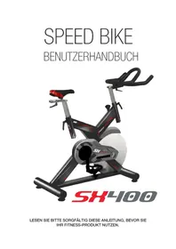
Exterior view of a modern exercise bike (no signage)LESEN SIE BITTE SORGFÄLTIG DIESE ANLEITUNG, BEVOR SIE IHR FITNESS-PRODUKT NUTZEN.
INHALTSVERZEICHNIS
SEITE
| NR. # NAME MENGE SPEZ | |||
| 1 PEDAL 1 JD-304 (9/16") | |||
| 2 ENDKAPPE 1 4 | 76 | ||
| 3 PASSBOLZEN 4 GB/T 12-1988 M10*90 | |||
| 4 STANDFUß HINTEN 1 WELDING | |||
| 5 UNTERLEGSCHEIBE GEBOGEN 4 | 10 | ||
| 6 | HUTMUTTER 5 | GB/T 802-1988 M10 | |
| 7 | FLASCHE | 1 | 73*215 |
| 8 | BOLZEN 2 GB/T 5780-2000 M8*40 | ||
| 9 KUGELLAGER 4 | 608ZZ | ||
| 10 | SATTELSTÜTZE | 1 WELDING | |
| 11 | ENDKAPPE 2 2 | 38*38*1,5 | |
| 12 | SATTELHALTERUNG | 1 WELDING | |
| 13 | SATTEL | 1 DD-268 | |
| 14 | GUMMIFUß | 4 | 52*39 |
| 15 | STANDFUß VORNE | 1 | WELDING |
| 16 | HAUPT-RAHMEN | 1 WELDING | |
| 17 | LENKERSTANGE | 1 WELDING | |
| 18 | LENKER | 1 WELDING | |
| 19 | L-GRIFF | 2 | M10*25 |
| 20 | UNTERLEGSCHEIBE FLACH 1 | 3 | 45* 10,5*4 |
| 21 | TRANSPORTROLLE | 2 | 69*23 |
| 22 | GETRÄNKEHALTER | 1 | 6 |
| 23 COMPUTER 1 | S-8210 | ||
| 24 | MUTTER | 6 | GB/T 889.1-2000 M8 |
| 25 | BOLZEN 1 | 1 GB/T77-2007 M6*6 | |
| 26 | L-GRIFF | 2 | (M16*1,5)*20mm |
| 27 | BOLZEN 1 | 4 | GB/T 70.2-2000 M8*16 |
| 28 | BEFESTIGUNGSMUTTER 1 | 2 | GB/T 6177.2-2000 M10*1,25 |
| 29 | KURBEL ENDENKAPE 1 | 28*6,5 | |
| 30 DRE-H-KNAUF 1 | 60*113 | ||
| 31 | MUTTER | 2 | GB/T 41-2000 M10 |
| 32 | FESTSTELLSCHRAUBE | 1 | 20*34 |
| 33 | LINKER PEDALARM | 1 | 170*15 |
| 34 | PEDALARM ABDECKUNG | 1 | 56*28 |
| 35 KUGELLAGER 4 | 6004ZZ | ||
| 36 | RECHTER PEDALARM | 1 | 170*15 |
| 37 GEWINDESTANGE 1 | 13,5*187 | ||
| 38 | UNTERLEGSCHEIBE 2 | 3 | 20* 14*2,0 |
| 39 | PLASTIK EINSCHUB 1 | 2 | 38*38*1,5 |
| 40 | BOLZEN 10 | 1 | M10*21 |
| 41 | SCHRAUBE 2 | 9 | GB/T 15856.1-2002 ST4,2*19 |
| NR # NAME Menge SPEZ | |||
| 42 SCHAFT 1 | 25*45 | ||
| 43 SCHRAUBE 3 2 GB/845-85 ST4,8*13 | |||
| 44 KETTENGEHÄUSE AUSSEN 1 575*260*45 | |||
| 45 KUGELLAGER 2 6203ZZ | |||
| 46 ACHSE 1 | 20*162 | ||
| 47 ABSTANDSHALTER LANG | 1 | 25* 20,2*41,2 | |
| 48 ABSTANDSHALTER KURZ | 1 | 25* 20,5*12 | |
| 49 | KETTENGEHÄUSE INNEN | 1 287*254*10 | |
| 50 | ANTRIEBSRIEMEN | 1 | 5P1180 |
| 51 | RIEMENRAD | 1 | 200*24 |
| 52 | SCHRAUBE 10 | 1 GB/845-85 ST4,8*13 | |
| 53 | FEDER 1 | 1 | 18*62 |
| 54 | BEFESTIGUNGSMUTTER 3 | 1 | M20*1,0 |
| 55 BOLZEN 3 | 4 | GB/T 5780-2000 M5*10 | |
| 56 | SCHWUNGRAD GEHÄUSE | 1 | 294*71*92 |
| 57 | UNTERLEGSCHEIBE FLACH 1 | 2 | GB/T 95-2002 10 |
| 58 | WELLENMUTTER | 1 | 18*11 |
| 59 BOLZEN 4 | 1 | GB/T 70,1-2000 M6*40 | |
| 60 | MUTTER 2 | 2 | GB/T 41-2000 M6 |
| 61 | SCHWUNGRAD | 1 | 460*17,5 |
| 62 | SCHWUNGRAD-ACHSE | 1 | 49*90 |
| 63 BOLZEN 5 | 1 | GB/T 70.1-2000 M6*20 | |
| 64 BOLZEN 6 | 4 | GB/T 70.1-2000 M6*30 | |
| 65 | UNTERLEGSCHEIBE FLACH | 8 | GB/T 95-2002 6 |
| 66 | BEFESTIGUNGSMUTTER | 2 | 27*M20*1 |
| 67 | SCHWUNGRAD HALTERUNG | 2 | 129*56,5*15 |
| 68 | BOZEN 7 | 4 | GB/T 70.1-2000 M6*12 |
| 69 | BOZEN8 2 | GB/T 70.1-2000 M6*12 | |
| 70 | EINSTELL-BLECH | 1 | 117*14,5* 1,5 |
| 71 | BREMSBLOCK | 1 | 161*21*19 |
| 72 | BREMSBELAG | 1 | 156*15,5*10 |
| 73 BOLZEN 9 | 2 | GB/T 5780-2000 M5*10 | |
| 74 | FEDERSCHEIBE 1 | 2 | GB/T 859-1987 5 |
| 75 | FEDERSCHEIBE 2 | 8 | GB/T 859-1987 6 |
| 76 | KLEINES RIEMENRAD | 1 | 64*23 |
| 77 | BEFESTIGUNGSMUTTER | 2 | 27*6 |
| 78 | PULSMESSER KABEL | 1 | L=100 |
| 79 | SENSOR | 1 | SR-202 |
| 80 | PULSMESSER-KABEL | 1 | L=800 |
| 81 | PULSMESSER | 2 | |
| 82 SCHRAUBE 5 2 GB/845-85 ST4,2*25 | |||
3. AUFBAUANLEITUNG:
1. BEACHTEN SIE:
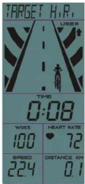
Workout mode selection
Target Time-> Target Distance-> Target Calories-> Target H.R.
Schnellstart
kompatible Fitness Apps

iBiking+
natural_image
Exterior view of a sports bike with visible branding and model number SH4100 (no text-heavy elements)PLEASE READ THIS MANUAL CAREFULLY BEFORE USING THIS BIKE
TABLE OF CONTENTS
PAGE
- Important safety notice 01
- Exploded View & part list 04
- Assembly instructions 08
- Adjustment 11
- Console operation-manual 14
1. IMPORTANT SAFETY NOTICE
Note the following precaution before assembling or operating the machine.
- Keep children and pets away from the Spinning Bike at all times. DO NOT leave unattended children in the same room with the machine.
- Handicapped or disabled persons should not use the spinning Bike without the presence of a qualified health professional or physician.
- If the user experiences dizziness, nausea, chest pain, or any other abnormal symptoms, STOP the workout at once. CONSULT A PHYSICIAN IMMEDIATELY.
- Before beginning training, remove all within a radius of 2 meters from the machine. DO NOT place any sharp objects around the Spinning Bike.
- Position the Spinning Bike on a clear, level surface away from water and moisture. Place mat under the unit to help keep the machine stable and to protect the floor.
- Use the Spinning Bike only for its intended use as described in this manual. DO NOT use any other accessories not recommended by the manufacturer.
- Assemble the machine exactly as the descriptions in the instruction manual.
- Check all bolts and other connections before using the machine for the first time and ensure that the trainer is in the safe condition.
- Hold a routine inspection of the equipment. Pay special attention to components which are the most susceptible to wear off, i.e. connecting points and wheels. The defective components should be replaced immediately. The safety level of this equipment can only be maintained by doing so. Please don't use the Spinning Bike until it is repaired well.
- NEVER operate the Spinning Bike if it is not functioning properly.
-
This machine can be used for only one person's training at a time.
-
Do not use abrasive cleaning articles to clean the machine. Remove drops of sweat from the machine immediately after finishing training.
- Always wear appropriate workout clothing when exercising. Running or aerobic shoes are also required.
- Before exercising, always do stretching first
- The power of the machine increases with increasing the speed, and the reverse. The machine is equipped with adjustable knob, which can adjust the resistance.
WARNING: BEFORE BEGINNING THIS OR ANY EXERCISE PROGRAM, CONSULT YOUR PHYSICIAN FIRST. THIS IS ESPECIALLY IMPORTANT FOR INDIVIDUALS OVER THE AGE OF 35 OR PERSONS WITH PRE-EXISTING HEALTH PROBLEMS. READ ALL INSTRUCTIONS BEFORE USING THE SPINNING BIKE. THANE ASSUMES NO RESPONSIBILITY FOR PERSONAL INJURY OR PROPERTY DAMAGE SUSTAINED BY OR THROUGH THE USE OF THIS PRODUCT
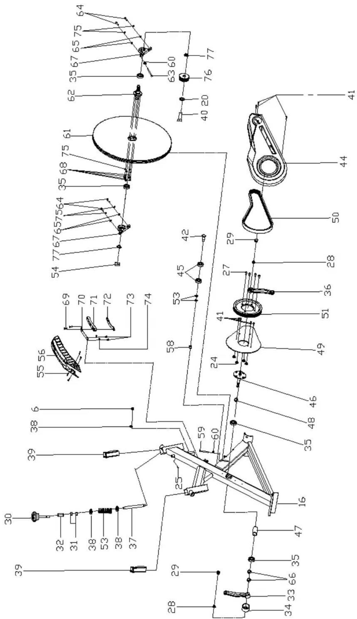
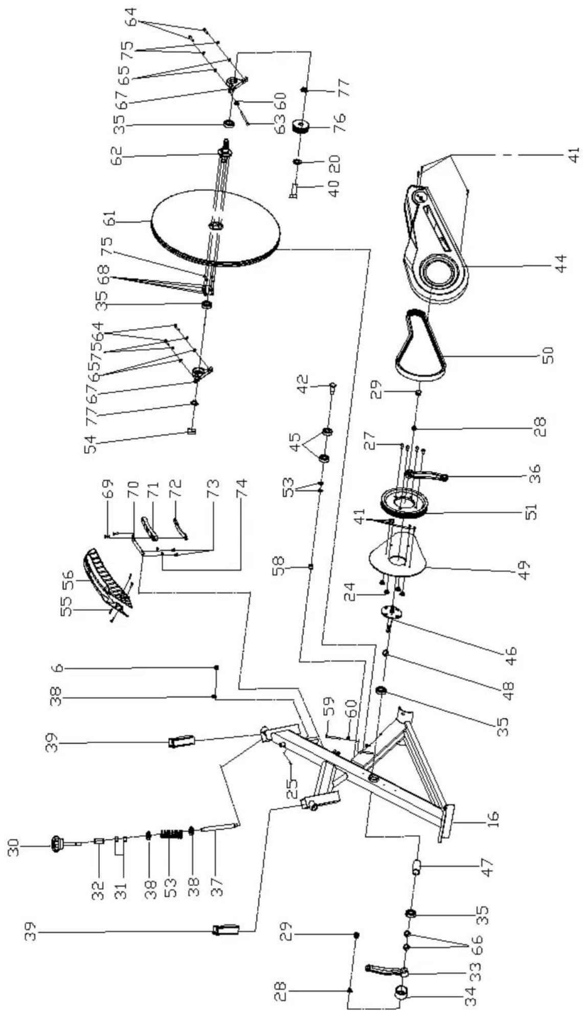
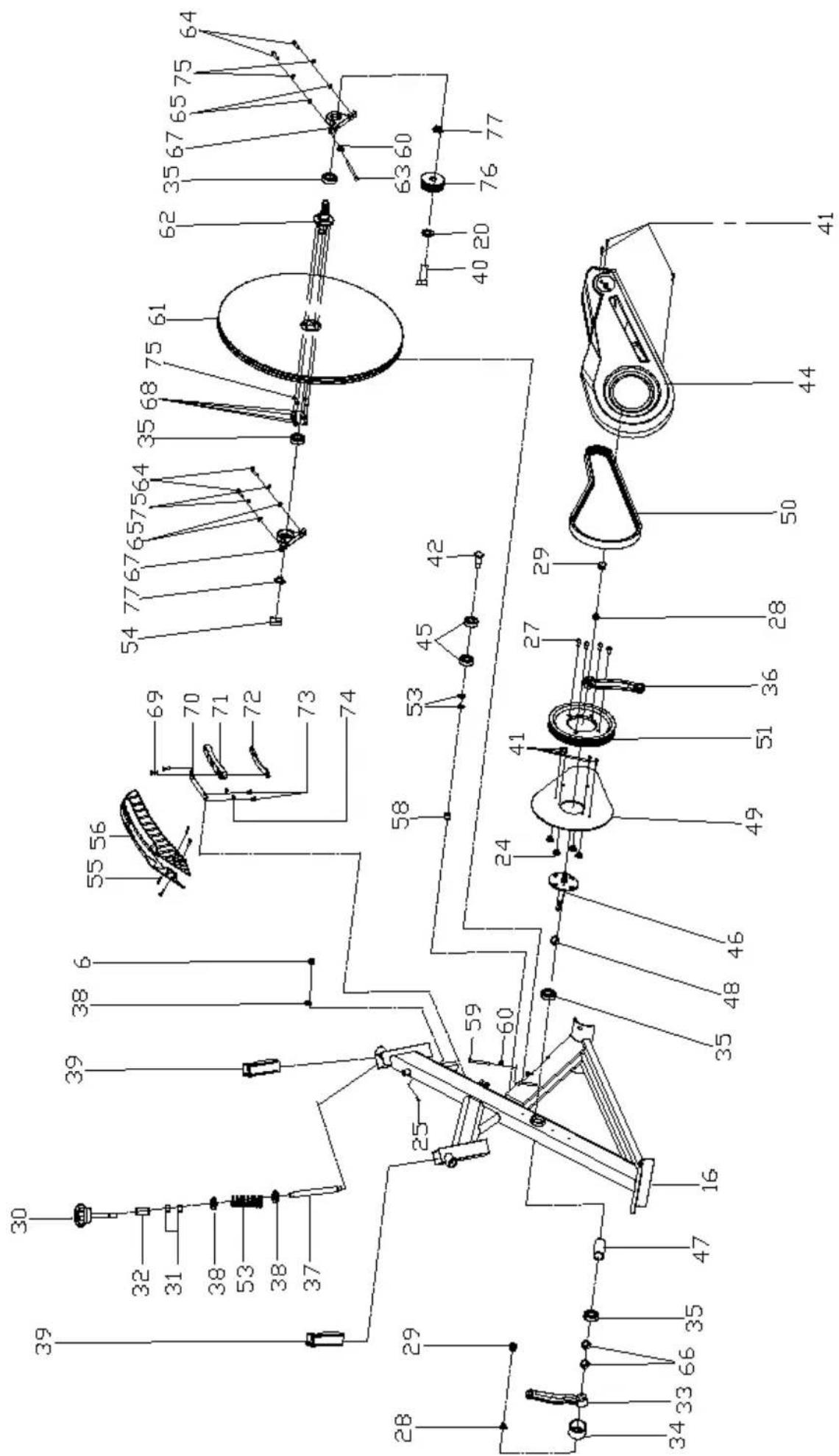
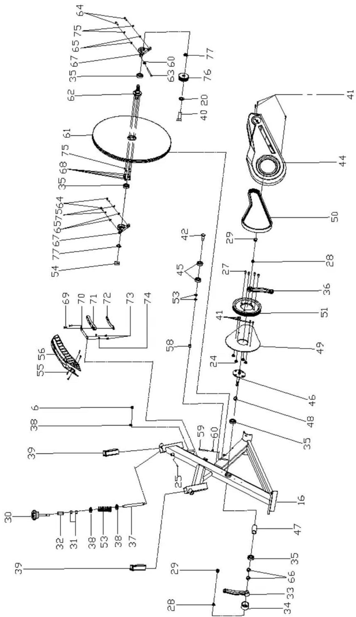
- EXPLODED-VIEW & PARTS LIST:
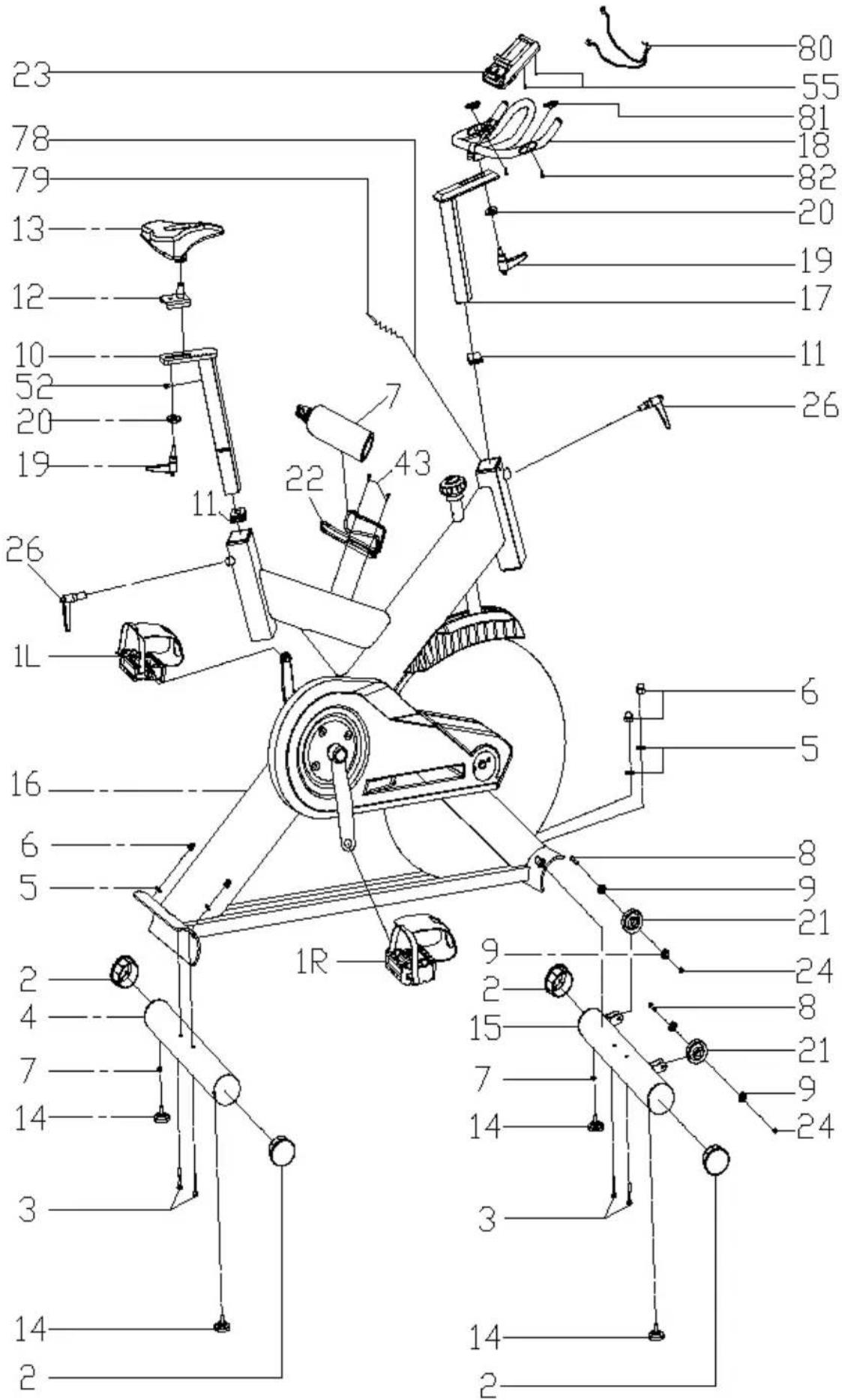
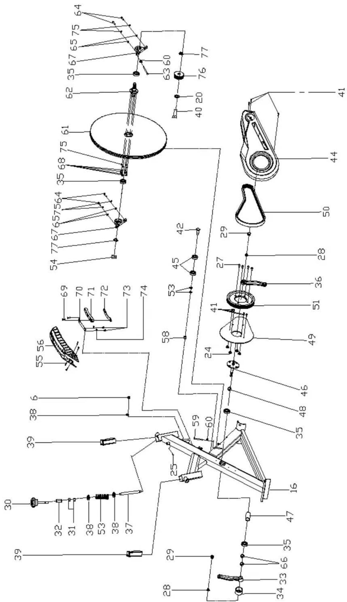
| No NAME QUANTITY SPEC | |||
| 1 PEDAL 1 JD-304 (9/16") | |||
| 2 END CAP 1 4 | φ76 | ||
| 3 CARRIAGE BOLT 4 GB/T 12-1988 M10*90 | |||
| 4 REAR STABILIZER 1 WELDING | |||
| 5 ARC WASHER 4 | φ10 | ||
| 6 DOMED NUT 5 GB/T 802-1988 M10 | |||
| 7 BOTTLE | 1 | φ73*215 | |
| 8 BOLT 2 GB/T 5780-2000 M8*40 | |||
| 9 BEARING | 4 | 608ZZ | |
| 10 VERTICAL SEAT POST | 1 WELDING | ||
| 11 END CAP 2 2 38*38*1,5 | |||
| 12 SEAT POST 1 WELDING | |||
| 13 SEAT 1 | DD-2681 | ||
| 14 STOPPER | 4 | φ52*39 | |
| 15 FRONT STABILIZER | 1 WELDING | ||
| 16 MAIN FRAME | 1 WELDING | ||
| 17 HANDLEBAR POST | 1 WELDING | ||
| 18 HANDLE BAR | 1 WELDING | ||
| 19 L SHAPE KNOB | 2 | M10*25 | |
| 20 FLAT WASHER 1 | 3 | φ45* φ10,5*4 | |
| 21 PU WHEEL | 2 | φ69*23 | |
| 22 BOTTLE HOLDER | 1 | φ6 | |
| 23 COMPUTER | 1 | SI-8210 | |
| 24 NUT | 6 | GB/T 889.1-2000 M8 | |
| 25 BOLT 1 1 GB/T77-2007 M6*6 | |||
| 26 L SHAPE KNOB | 2 (M16*1,5)*20mm | ||
| 27 BOLT 1 4 | GB/T 70.2-2000 M8*16 | ||
| 28 FIXING NUT 1 2 | GB/T 6177.2-2000 M10*1,25 | ||
| 29 CRANK END CAP | 1 | φ28*6,5 | |
| 30 KNOB 1 | φ60*113 | ||
| 31 NUT | 2 | GB/T 41-2000 M10 | |
| 32 TWIST THE FIXINGS | 1 | φ20*34 | |
| 33 LEFT CRANK 1 | 170*15 | ||
| 34 CRANK COVER 1 | φ56*28 | ||
| 35 BEARING | 4 | 6004ZZ | |
| 36 RIGHT CRANK 1 | 170*15 | ||
| 37 SCREW ROD 1 | φ13,5*187 | ||
| 38 WASHER 2 3 | φ20* φ14*2,0 | ||
| 39 PLASTIC SLEEVE 1 | 2 | 38*38*1,5 | |
| 40 BOLT 10 | 1 | M10*21 | |
| 41 SCREW 2 | 9 | GB/T 15856.1-2002 ST4,2*19 | |
| No NAME QUANTITY SPEC | |||
| 42 SHAFT 1 | 25*45 | ||
| 43 SCREW 3 2 GB/845-85 ST4,8*13 | |||
| 44 OUTER CHAIN COVER 1 575*260*45 | |||
| 45 BEARING 2 6203ZZ | |||
| 46 AXIS 1 | 20*162 | ||
| 47 LONG FIXING TUBE 1 | 25* 20,2*41,2 | ||
| 48 | SHORT FIXING TUBE | 1 | 25* 20,5*12 |
| 49 | INNER CHAIN COVER | 1 287*254*10 | |
| 50 | BELT | 1 | 5P1180 |
| 51 BELT WHEEL 1 | 200*24 | ||
| 52 | SCREW 10 | 1 GB/845-85 ST4,8*13 | |
| 53 SPRING 1 1 | 18*62 | ||
| 54 | FIXING NUT 3 1 | M20*1,0 | |
| 55 | BOLT 3 | 4 | GB/T 5780-2000 M5*10 |
| 56 | FLYWHEEL COVER 1 | 294*71*92 | |
| 57 | FLAT WASHER 1 | 2 | GB/T 95-2002 10 |
| 58 | SHAFT NUT | 1 | 18*11 |
| 59 | BOLT 4 | 1 GB/T 70 | 1-2000 M6*40 |
| 60 | NUT 2 | 2 | GB/T 41-2000 M6 |
| 61 | FLYWHEEL | 1 | 460*17,5 |
| 62 | FLYWHEEL SHAFT | 1 | 49*90 |
| 63 | BOLT 5 | 1 GB/T 70 | 1-2000 M6*20 |
| 64 | BOLT 6 | 4 GB/T 70 | 1-2000 M6*30 |
| 65 | FLAT WASHER | 8 | GB/T 95-2002 6 |
| 66 | FIXING NUT | 2 | 27*M20*1 |
| 67 | FLYWHEEL HOLDER | 2 | 129*56,5*15 |
| 68 | BOLT 7 | 4 GB/T 70 | 1-2000 M6*12 |
| 69 | BOLT 8 | 2 GB/T 70 | 1-2000 M6*12 |
| 70 | ADJUSTING METAL 1 | 117*14,5* 1,5 | |
| 71 | BLOCK | 1 | 161*21*19 |
| 72 | WOOLLY BLOCK | 1 | 156*15,5*10 |
| 73 | BOLT 9 | 2 | GB/T 5780-2000 M5*10 |
| 74 | SPRING WASHER 1 2 | GB/T 859-1987 5 | |
| 75 | SPRING WASHER 2 8 | GB/T 859-1987 6 | |
| 76 | LITTLE BELT WHEEL | 1 | 64*23 |
| 77 | FIXING NUT | 2 | 27*6 |
| 78 | PULSE WIRE | 1 | L=100 |
| 79 | SENSOR | 1 | SR-202 |
| 80 | PULSE WIRE | 1 | L=800 |
| 81 PULSE 2 | |||
| 82 SCREW 5 2 GB/845-85 ST4,2*25 | |||
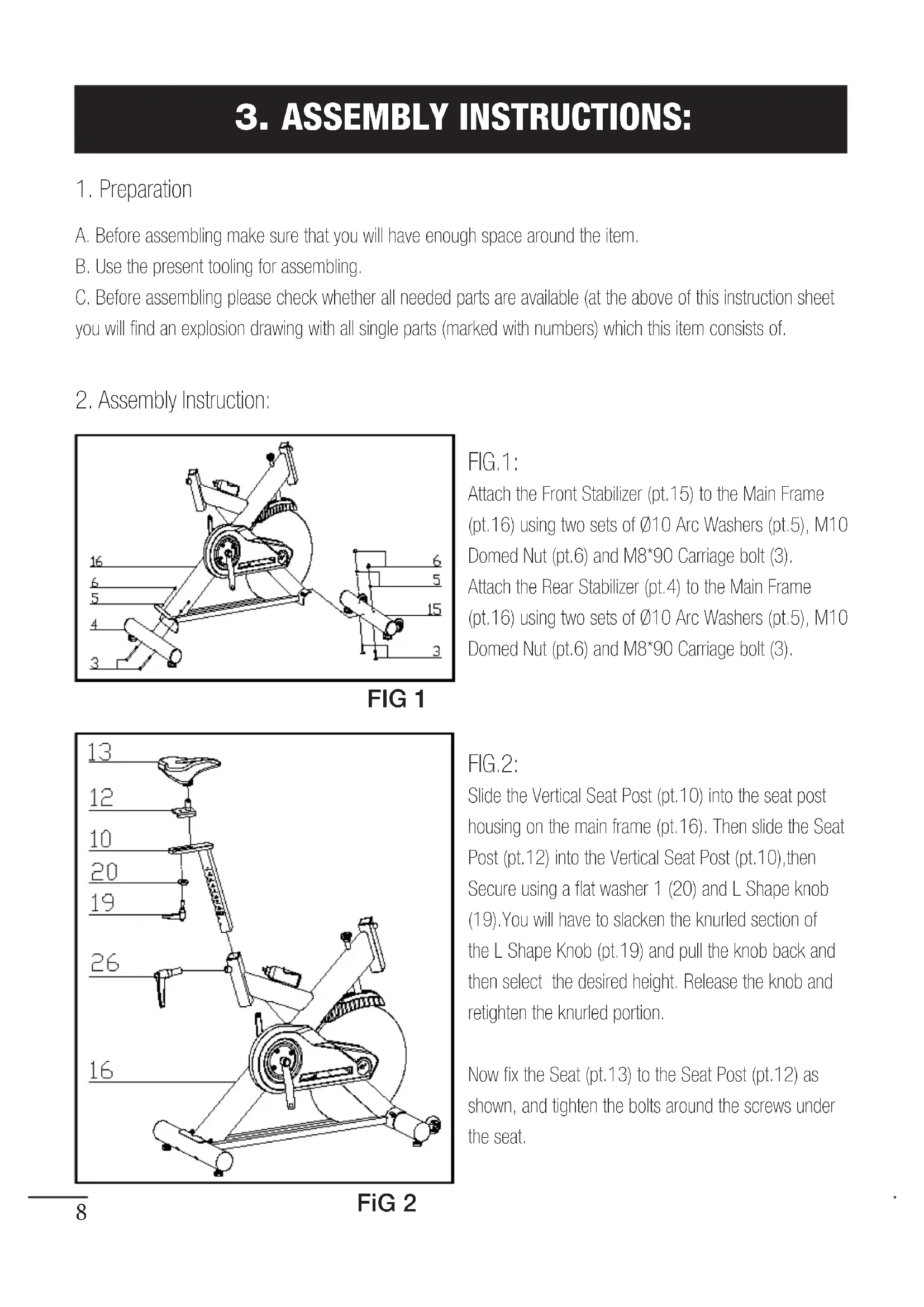
3. ASSEMBLY INSTRUCTIONS:
1. Preparation
A. Before assembling make sure that you will have enough space around the item.
B. Use the present tooling for assembling.
C. Before assembling please check whether all needed parts are available (at the above of this instruction sheet you will find an explosion drawing with all single parts (marked with numbers) which this item consists of.
2. Assembly Instruction:

FIG 1
FIG.1:
Attach the Front Stabilizer (pt.15) to the Main Frame (pt.16) using two sets of ∅10 Arc Washers (pt.5), M10 Domed Nut (pt.6) and M8*90 Carriage bolt (3). Attach the Rear Stabilizer (pt.4) to the Main Frame (pt.16) using two sets of ∅10 Arc Washers (pt.5), M10 Domed Nut (pt.6) and M8*90 Carriage bolt (3).
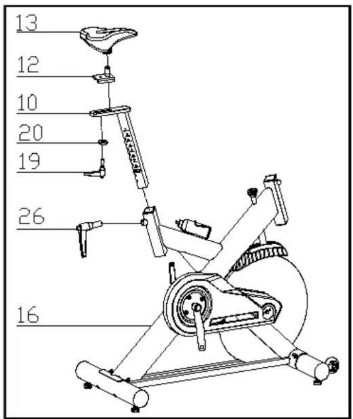
FIG.2:
Slide the Vertical Seat Post (pt.10) into the seat post housing on the main frame (pt.16). Then slide the Seat Post (pt.12) into the Vertical Seat Post (pt.10), then Secure using a flat washer 1 (20) and L Shape knob (19). You will have to slacken the knurled section of the L Shape Knob (pt.19) and pull the knob back and then select the desired height. Release the knob and retighten the knurled portion.
Now fix the Seat (pt.13) to the Seat Post (pt.12) as shown, and tighten the bolts around the screws under the seat.
FiG 2
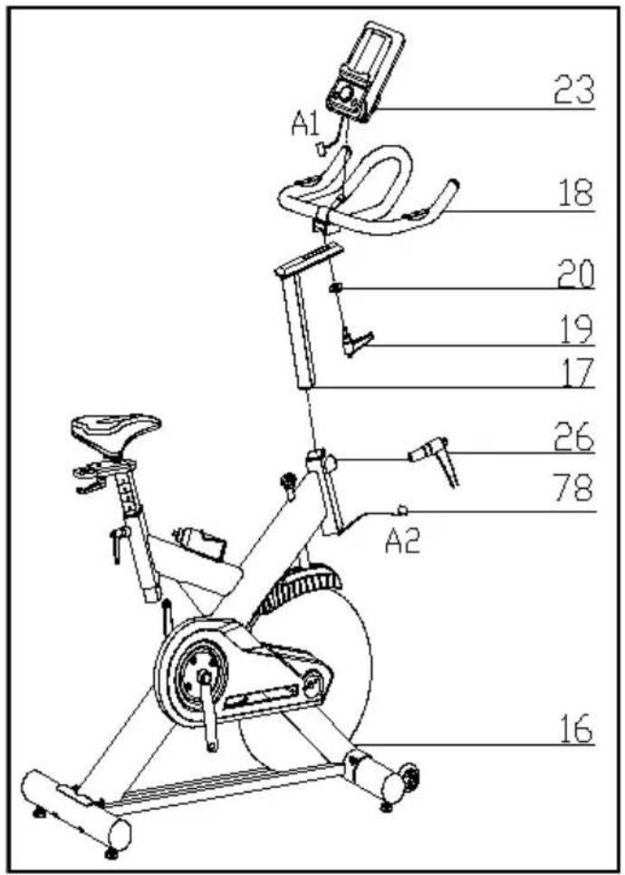
FIG 3
FIG.3:
Slide the Handlebar Post (pt.17) into the handlebar post housing on the main frame(pt.16). You will have to slacken the knurled section of the L Shape Knob (pt.26) and pull the knob back and then select the desired height. Release the knob and retighten the knurled portion.
Then fix the Handlebar (pt.18) with a flat washer 1 (20) and L Shape knob (19)
ATTENTION: YOU SHOULD FIX THE HANDLEBAR TIGHTLY
Fix the Computer (pt.78) onto the Computer Holder with bolt (pt.55), connect the plug (A1&A2),
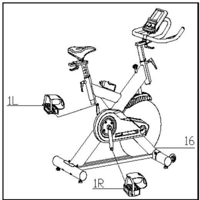
FiG 4
FIG.4:
The Pedals (pt.1 L & pt.1 R) are marked „L“ and „R“ - Left and Right. Connect them to their appropriate crank arms. The right crank arm is on the right- hand side of the cycle as you sit on it. Note that the Right pedal should be threaded on clockwise and the Left pedal counter-clockwise.
A.) Adjusting the Tension:
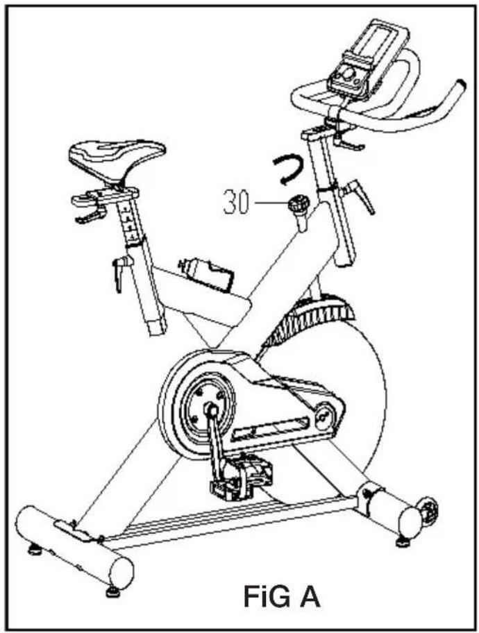
Increasing or decreasing the tension allows you to add variety to your workout sessions by adjusting the resistance level of the bike.
To increase tension and increase resistance (requiring more strength to pedal), turn the Emergency
Brake & Tension Control Knob (#30) to the right.
To decrease tension and increase resistance (requiring less strength to pedla), turn the Emergency
Brake & Tension Control Knob (#30) to the left.
B.) Using the Emergency Brake Function:
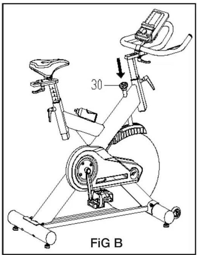
The same knob that allows you to adjust the tension of the bike also doubles as the Emergency
Brake. Use this safety feature in any situation where you would need to get off the bike and/or stop the bike's flywheel.
To use the Emergency Brake function in any situation you would need it in, firmly press down on the Emergency Brake & Tension Control Knob (#30).
4. ADJUSTMENT
*To adjust the seat height, slacken the spring knob on the vertical post stem on the main frame and pull back the knob. Position the vertical seat post for the desired height so that holes are aligned, then release the knob and retighten it.
*To move the seat forward in the direction of the handlebar or backwards away from it, loosen the adjusting knob and washer and pull the knob back. Slide horizontal seat post into desired position. Align holes and then retighten the adjusting knob.
*To adjust the handlebar height, slacken the spring knob and secondary knob and pull both knobs back. Slide the handlebar post along the housing on the main frame to the desired height and, with the holes aligned correctly, tighten the spring adjusting knob and then the secondary knob.
EXERCISE INSTRUCTIONS
Using your SPINNING BIKE provides you with several benefits, it will improve your physical fitness, tone muscle and in conjunction with calorie controlled diet help you lose weight.
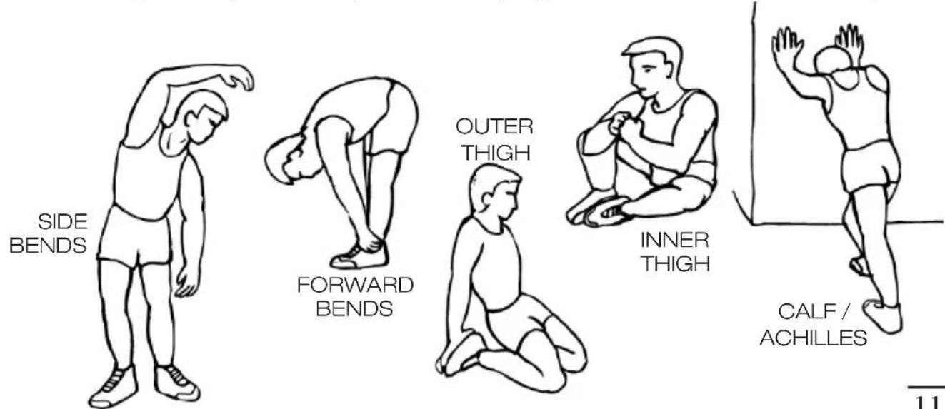
1. The Warm Up Phase
This stage helps get the blood flowing around the body and the muscles working properly. It will also reduce the risk of cramp and muscle injury. It is advisable to do a few stretching exercises as shown below. Each stretch should be held for approximately 30 seconds, do not force or jerk your muscles into a stretch - if it hurts, STOP.
2.The Exercise Phase
This is the stage where you put the effort in. After regular use, the muscles in your legs will become Stronger. Work to your but it is very important to maintain a steady tempo throughout. The rate of work should be sufficient to raise your heart beat into the target zone shown on the graph below.
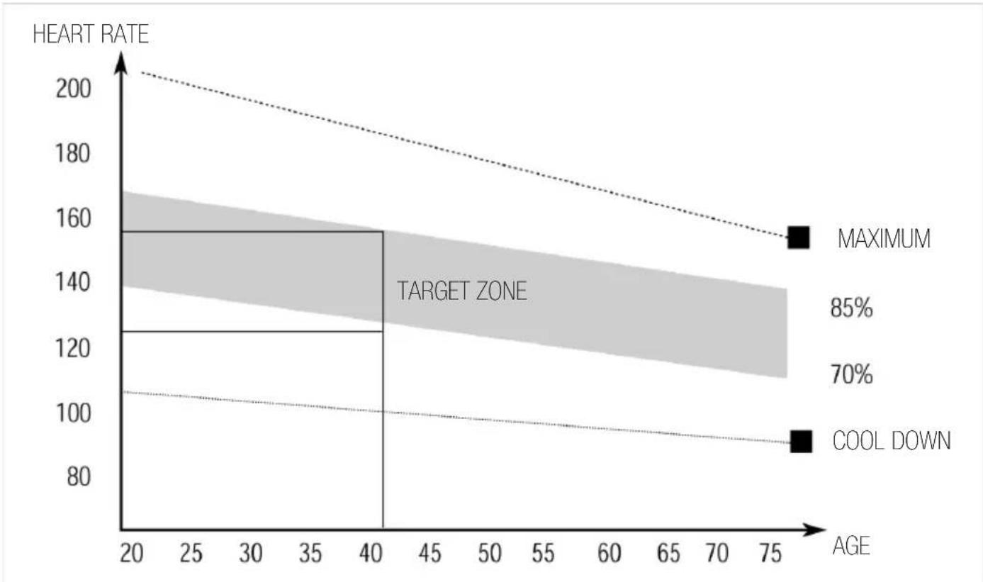
line
| AGE | HEART RATE | | --- | --- | | 20 | 200 | | 40 | 160 | | 75 | 155 |This stage should last for a minimum of 12 minutes for most people
This stage is to let your Cardio-vascular System and muscles wind down. This is a repeat of the warm up exercise e.g. reduce your tempo, continue for approximately 5 minutes. The stretching exercises should now be repeated, again remembering not to force or jerk your muscles into the stretch.
As you get fitter you may need to train longer and harder. It is advisable to train at least three times a week, and if possible space your workouts evenly throughout the week.
MUSCLE TONING
To tone muscle while on your SPINNING BIKE you will need to have the resistance set quite high. This will put more strain on our leg muscles and may mean you cannot train for as long as you would like. If you are also trying to improve your fitness you need to alter your training program. You should train as normal during the warm up and cool down phases, but towards the end of the exercise phase you should increase resistance, making your legs work harden than normal. You may have to reduce your speed to keep your heart rate in the target zone.
WEIGHT LOSS
The important factor here is the amount of effort you put in. The harder and longer you work the more calories you will burn. Effectively this is the same as if you were training to improve your fitness, the difference is the goal.
USE
The tension control knob allows you to alter the resistance of the pedals. A high resistance makes it more difficult to pedal, a low resistance makes it easier. For the best results set the tension while the bike is in use.
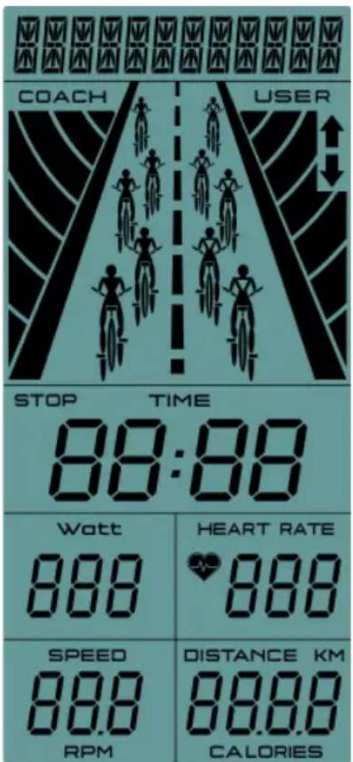
| Item Description | |
| Time .Display user workout time. .Display range 0:00 ~ 99:59 | |
| SPEED .Display user workout speed. .Display range 0.0 ~ 99.9 | |
| DISTANCE .Display user workout distance. .Display range 0.0 ~ 99.9 | |
| CALORIES .Display calories consumption during workout . .Display range 0 ~ 999 | |
| HEART RATE .Display user pulse during workout . .When user pulse exceed preset target value, monitor will alarm with Bi-bi sound. | |
| RPM .Revolution per minute. .Display range 0 ~ 999 | |
Button function
| Item Description | |
| Joggle wheel - Up | Adjust function value or selection up. |
| Joggle wheel - Down | Adjust function value or selection down. |
| Mode Confirm setting or selection. | |
| Reset Hold on for 2s, monitor will reboot.During setting or Stop mode, press it to go back to main menu . | |
| Start/Stop Start or stop workout. | |
Operation procedure:
Power on--
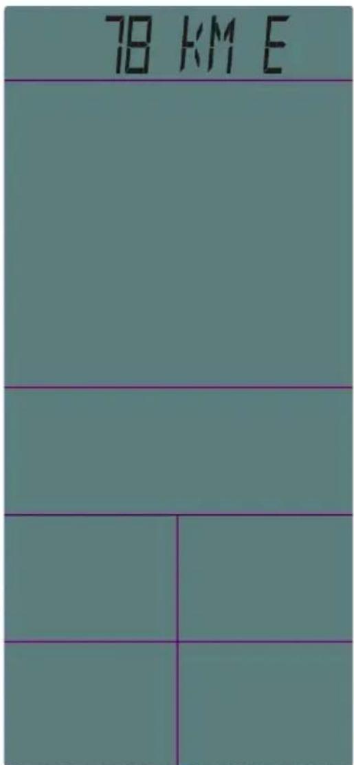
Install 4PCS AA batteries (or press RESET KEY for 2s), monitor will power on along with BUZZER sound 1s, LCD will show all segments 2s then display wheel diameter and unit 1s. Then go to USER setting mode. Without any signal input for 4 minutes, monitor will go to Sleeping mode. Press any key to wake up monitor.
User data setting--
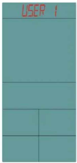
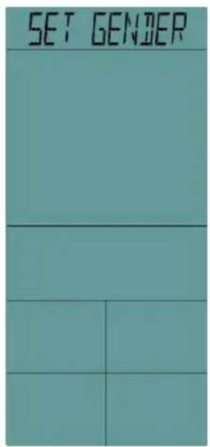
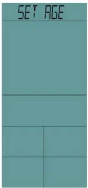
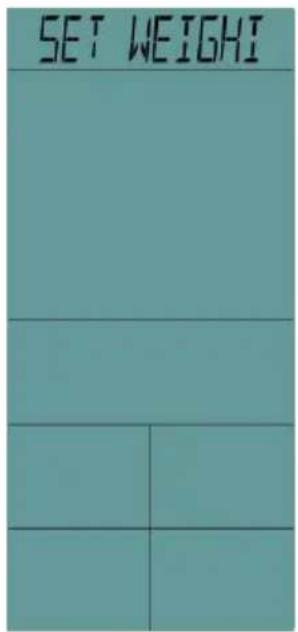
Use joggle wheel to select USER group from U1\~U4, press MODE to confirm.
Set Gender/ Age/ Height/ Weight, them come to workout page.
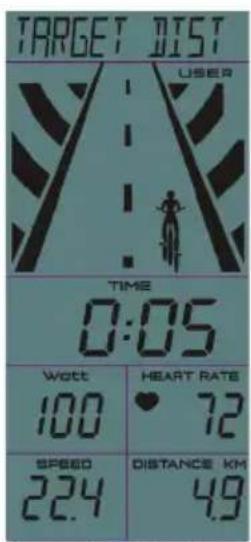
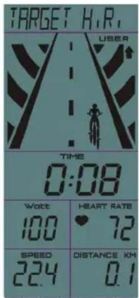
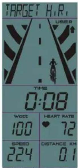
Workout mode selection
Use joggle wheel to select workout mode as: Target Time->Target Distance->Target Calories->Target H.R.
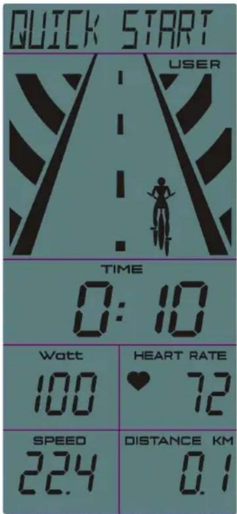
Quick start
- Start workout directly, TIME begins to count up. DISTANCE/ CALORIES/ RPM/ SPEED & HEART RATE will display value accordingly.
- The character animation only show USER, it will skip to next figure as per 0.1KM (or ML).
- Press STRAT/STOP button to stop workout, STOP icon is blinking, all value will remain.
- During workout, it is invalid to press RESET /Joggle wheel /ENTER button.
- In STOP mode, press RESET button, monitor return to function setting page.
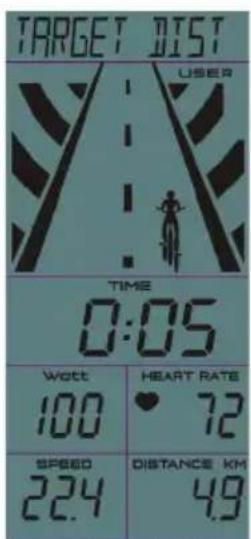
Target Time
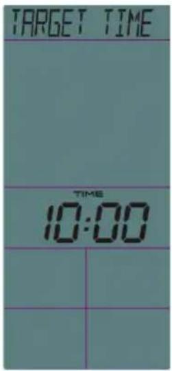
- Use joggle wheel to set Target TIME (preset value=10:00), press STRAT/STOP to workout in Target Time mode.
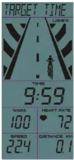
- TIME begins to count down from Target value, DISTANCE/ CALORIES/ RPM/ SPEED & HEART RATE will display value accordingly.
- The character animation only show USER, it will skip to next figure as per one fifth of the preset Time.
- Press STRAT/STOP button to stop workout, STOP icon is blinking, all value will remain.
- During workout, it is invalid to press RESET /Joggle wheel /ENTER button.
- In STOP mode, press RESET button, monitor return to function setting page.
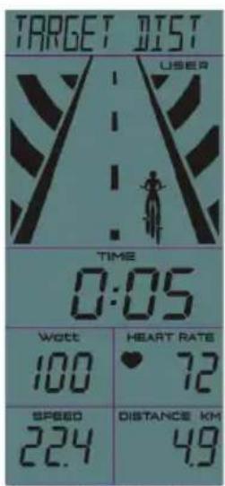
Target Distance
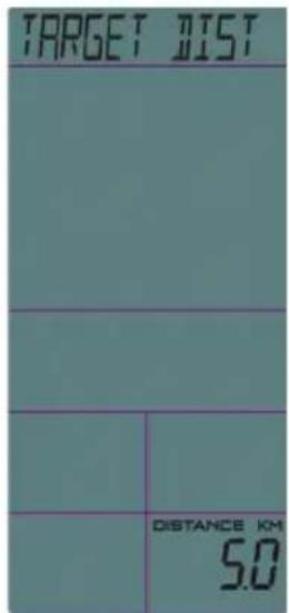
- Use joggle wheel to set Target DISTANCE (preset value=5.0), press STRAT/STOP to workout in Target Distance mode.
- DISTANCE begins to count down from Target value, TIME/ CALORIES/ RPM/ SPEED & HEART RATE will display value accordingly.
- The character animation only show USER, it will skip to next figure as per one fifth of the preset Distance.
- Press STRAT/STOP button to stop workout, STOP icon is blinking, all value will remain.
- During workout, it is invalid to press RESET /Joggle wheel /ENTER button.
- In STOP mode, press RESET button, monitor return to function setting page.
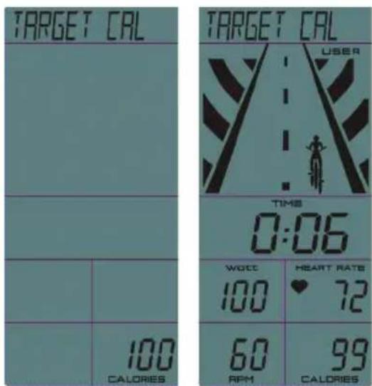
Target Calories
- Use joggle wheel to set Target CALORIES (preset value=100), press STRAT/STOP workout in Target Calories mode.
- CALORIES begins to count down from Target value, TIME/DISTANCE/RPM/SPEED & HEART RATE will display value accordingly.
- The character animation only show USER, it will skip to next figure as per one fifth of the preset Calories.
- Press STRAT/STOP button to stop workout, STOP icon is blinking, all value will remain.
- During workout, it is invalid to press RESET /Joggle wheel /ENTER button.
- In STOP mode, press RESET button, monitor return to function setting page.
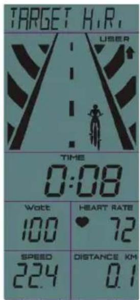
Target HR
- Use joggle wheel to set Target PULSE (preset value=100), press STRAT/STOP to workout in Target HR. Mode. Keep both hands hold on hand grips.
- TIME begins to count up, DISTANCE/ CALORIES/ RPM/ SPEED & HEART RATE will display value accordingly.
- The character animation only show USER, it will skip to next figure as per 0.1KM (or ML).
- When actual PULSE value is 50% higher than Target Pulse, ↑ is flashing to remind user too fast; When actual PULSE is 50% lower than Target Pulse, ↓ is flashing to remind user too slow.
- Press STRAT/STOP button to stop workout, STOP icon is blinking, all value will remain.
- During workout, it is invalid to press RESET /Joggle wheel /ENTER button.
- In STOP mode, press RESET button, monitor return to function setting page.

compatible fitness applications

iBiking+
Android: Download your favorite application from the Google PlayStore.
iPad/iPhone: Download your favorite application from the AppStore.
Check if your mobile device confirms the requirements for the application.
The requirements of each application are shown in the Google PlayStore or AppStore.
How to use:
Connect the included jack-in cable (headphone connector) to the console and to the headphone connector of your Smartphone or Tablet.
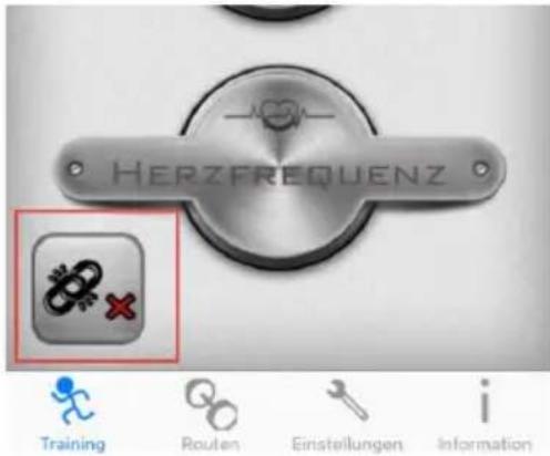
Open the application on your smartphone or tablet. Select the marked button at the bottom left side.
Choose the function „TuneLinc“ and follow the steps shown on the display
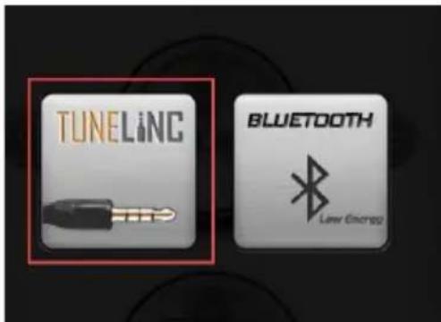
The devices are paired when the red cross switches to a green checkmark.
After this you can operate your device through the application.
European Disposal Directive 2002/96/EG
Never dispose your training device in your regular household waste.
Dispose the device only at a local or approved disposal. Take care of the currently applicable regulations. If you have doubts contact your local authorities for information about a correct and environment friendly disposal option.
batteries/rechargable batteries
In accordance with the battery regulation you are legally obliged as an end user to return all used batteries. Disposal in the regular household waste is forbidden by law.
On the most batteries you will find the symbol which remember you about this regulation. Beside this symbol there is usually information about the contained heavy metal. Such heavy metals require an environment friendly disposal. As an end user you are legally obliged to submit used batteries at the appropriate collection point of your city or commercially.
If you have doubts contact your local authorities for information about a correct and environment friendly disposal option.
warranty
Fill in the following field, to register your device for the warranty.
device-information:
product name/model: SPORTSTECH SX400
serial number:
purchase date: ____
invoice number:
personal information:
forname/last name:
street :
city code/city:
country:
E-Mail:
phone number*: ____
*voluntary information, the remaining fields are required and must be filled out.
I have read the warranty conditions and product specific operation/maintenance instructions and accept them with my signature. For warranty purposes I agree with the saving of my personal data.
The warranty conditions can be viewed at: www.sportstech.de/garantie
date
city
signature
Send the filled out warranty card by letter* to the following address:
InnovaMaxx GmbH, Potsdamer Str. 144, D-10783 Berlin
* sufficient postage necessary - letters without sufficient postage cannot be accepted
InnovaMaxx GmbH
Potsdamer Str. 144
D-10783 Berlin
natural_image
Exterior view of a sports bike (no signage or text in focus)VEUILLEZ LIRE ATTENTIVEMENT CE GUIDE AVANT L'UTILISATION DU VELO
TABLE DES MATIERES
PAGE
| No | NOM | QUANTITE SPEC | |
| 1 | Pédales | 1 | JD-304 (9/16") |
| 2 | EMBOUT 1 | 4 φ 76 | |
| 3 | BOULON | 4 | GB/T 12-1988 M10*90 |
| 4 | STABILISATION ARRIÈRE | 1 | SOUDURE |
| 5 | LAVEUSE | 4 φ 10 | |
| 6 | ÉCROU dôme | 5 | GB/T 802-1988 M10 |
| 7 | BOUTEILLE | 1 | φ 73*215 |
| 8 | BOULON | 2 | GB/T 5780-2000 M8*40 |
| 9 | SUPPORT | 4 | 608ZZ |
| 10 | SIEGE VERTICAL | 1 | SOUDURE |
| 11 | EMBOUT 2 | 2 | 38*38*1,5 |
| 12 | POSTE | 1 | SOUDURE |
| 13 | SIEGE | 1 | DD-2681 |
| 14 | STOPPEUR | 4 | φ 52*39 |
| 15 | FRONT DE STABILISATION | 1 | SOUDURE |
| 16 | Châssis principal | 1 | SOUDURE |
| 17 | GUIDON | 1 | SOUDURE |
| 18 | GUIDON | 1 | SOUDURE |
| 19 | KNOB FACONNE | 2 | M10*25 |
| 20 | RONDELLE PLATE 1 | 3 | φ 45* φ 10,5*4 |
| 21 | ROUE | 2 | φ 69*23 |
| 22 | Support de bouteille | 1 φ 6 | |
| 23 | Ordinateur | 1 | SI-8210 |
| 24 | ÉCROU | 6 | GB/T 889.1-2000 M8 |
| 25 | BOULON 1 | 1 | GB/T77-2007 M6*6 |
| 26 | Rondelle plate | 2 | (M16*1,5)*20mm |
| 27 | BOULON 1 | 4 | GB/T 70.2-2000 M8*16 |
| 28 | ÉCROU 1 | 2 | GB/T 6177.2-2000 M10*1,25 |
| 29 | MANIVELLE | 1 | φ 28*6,5 |
| 30 | BOUTON | 1 | φ 60*113 |
| 31 | ÉCROU | 2 | GB/T 41-2000 M10 |
| 32 | TOURNER LES FIXATIONS | 1 | φ 20*34 |
| 33 | MANIVELLE GAUCHE | 1 | 170*15 |
| 34 | Couverture de manivelle | 1 | φ 56*28 |
| 35 | SUPPORT | 4 | 6004ZZ |
| 36 | MANIVELLE DROITE | 1 | 170*15 |
| 37 | VIS | 1 | Φ 13,5*187 |
| 38 | LAVEUSE 2 | 3 | φ 20* φ 14*2,0 |
| 39 | MANCHE PLASTIQUE 1 | 2 | 38*38*1,5 |
| 40 | BOULON 10 | 1 | M10*21 |
| 41 | VIS 2 | 9 | GB/T 15856.1-2002 ST4,2*19 |
| 5 | LAVEUSE | 4 φ 10 | |
| 6 | ÉCROU dôme | 5 | GB/T 802-1988 M10 |
| 7 | BOUTEILLE | 1 | φ 73*215 |
| 8 | BOULON | 2 | GB/T 5780-2000 M8*40 |
| 9 | SUPPORT | 4 | 608ZZ |
| 10 | SIEGE VERTICAL | 1 | SOUDURE |
| 11 | EMBOUT 2 | 2 | 38*38*1,5 |
| 12 | POSTE | 1 | SOUDURE |
| 13 | SIEGE | 1 | DD-2681 |
| 14 | STOPPEUR | 4 | φ 52*39 |
| 15 | FRONT DE STABILISATION | 1 | SOUDURE |
| 16 | Châssis principal | 1 | SOUDURE |
| 17 | GUIDON | 1 | SOUDURE |
| 18 | GUIDON | 1 | SOUDURE |
| 19 | KNOB FACONNE | 2 | M10*25 |
| 20 | RONDELLE PLATE 1 | 3 | φ 45* φ 10,5*4 |
| 21 | ROUE | 2 | φ 69*23 |
| 22 | Support de bouteille | 1 φ 6 | |
| 23 | Ordinateur | 1 | SI-8210 |
| 24 | ÉCROU | 6 | GB/T 889.1-2000 M8 |
| 25 | BOULON 1 | 1 | GB/T77-2007 M6*6 |
| 26 | Rondelle plate | 2 | (M16*1,5)*20mm |
| 27 | BOULON 1 | 4 | GB/T 70.2-2000 M8*16 |
| 28 | ÉCROU 1 | 2 | GB/T 6177.2-2000 M10*1,25 |
| 29 | MANIVELLE | 1 | φ 28*6,5 |
| 30 | BOUTON | 1 | φ 60*113 |
| 31 | ÉCROU | 2 | GB/T 41-2000 M10 |
| 32 | TOURNER LES FIXATIONS | 1 | φ 20*34 |
| 33 | MANIVELLE GAUCHE | 1 | 170*15 |
| 34 | Couverture de manivelle | 1 | φ 56*28 |
| 35 | SUPPORT | 4 | 6004ZZ |
| 36 | MANIVELLE DROITE | 1 | 170*15 |
| 37 | VIS | 1 | Φ 13,5*187 |
| 38 | LAVEUSE 2 | 3 | φ 20* φ 14*2,0 |
| 39 | MANCHE PLASTIQUE 1 | 2 | 38*38*1,5 |
| 40 | BOULON 10 | 1 | M10*21 |
| 41 | VIS 2 | 9 | GB/T 15856.1-2002 ST4,2*19 |
3. INSTRUCTIONS D'ASSEMBLAGE:
1. PRÉPARATION:
line
| ÂGE | RYTHME CARDIAQUE | | --- | --- | | 20 | 200 | | 40 | 160 | | 75 | 150 |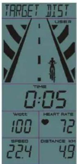
Calories cibles
Applications de fitness compatibles
iBiking+
natural_image
Exterior view of a modern exercise bike (no signage)INDICE
PAG.
- IMPORTANTI INFORMAZIONI SULLA SICUREZZA 01
- DISEGNO ESPLOSO E LISTA DEI COMPONENTI 04
- ISTRUZIONI PER L'ASSEMBLAGGIO 08
- REGOLAZIONE 11
- MANUALE OPERATIVO DELLA CONSOLE 14
1. IMPORTANTI INFORMAZIONI SULLA SICUREZZA
| No | NOME | QUANTITÀ SPEC | |
| 1 | PEDALE | 1 | JD-304 (9/16") |
| 2 | CAPPUCCIO | 4 φ 76 | |
| 3 | BULLONE CARRELLO | 4 | GB/T 12-1988 M10*90 |
| 4 | STABILIZZATORE RETRO | 1 | SALDATURA |
| 5 | RONDELLA AD ARCO | 4 φ 10 | |
| 6 | DADO A CUPOLA | 5 | GB/T 802-1988 M10 |
| 7 | BOTTIGLIA | 1 | φ 73*215 |
| 8 | BULLONE | 2 | GB/T 5780-2000 M8*40 |
| 9 | SOSTEGNO | 4 | 608ZZ |
| 10 | PALO SEDILE VERTICALE | 1 | SALDATURA |
| 11 | CAPPUCCIO | 2 | 38*38*1,5 |
| 12 | PALO SEDILE | 1 | SALDATURA |
| 13 | SEDILE | 1 | DD-2681 |
| 14 | TAPPO | 4 | φ 52*39 |
| 15 | STABILIZZATORE | 1 | SALDATURA |
| 16 | STRUTTURA | 1 | SALDATURA |
| 17 | PALO MANUBRIO | 1 | SALDATURA |
| 18 | MANUBRIO | 1 | SALDATURA |
| 19 | MANIGLIA A L | 2 | M10*25 |
| 20 | RONDELLA PIATTA 1 | 3 | φ 45* φ 10,5*4 |
| 21 | RUOTA PU | 2 | φ 69*23 |
| 22 | PORTA BOTTIGLIA | 1 φ 6 | |
| 23 | COMPUTER | 1 | SI-8210 |
| 24 | DADO | 6 | GB/T 889.1-2000 M8 |
| 25 | BOLT 1 | 1 | GB/T77-2007 M6*6 |
| 26 | L SHAPE KNOB | 2 | (M16*1,5)*20mm |
| 27 | BULLONE 1 | 4 | GB/T 70.2-2000 M8*16 |
| 28 | DADO FISSAGGIO 1 | 2 | GB/T 6177.2-2000 M10*1,25 |
| 29 | CAPPUCCIO MANOVELLA | 1 | φ 28*6,5 |
| 30 | MANIGLIA | 1 | φ 60*113 |
| 31 | DADO | 2 | GB/T 41-2000 M10 |
| 32 | GUARNIZIONI | 1 | φ 20*34 |
| 33 | MANOVELLA SINISTRA | 1 | 170*15 |
| 34 | COPERTURA | 1 | φ 56*28 |
| 35 | SOSTEGNO | 4 | 6004ZZ |
| 36 | MANOVELLA DESTRA | 1 | 170*15 |
| 37 | ASTA VITE | 1 | Φ 13,5*187 |
| 38 | RONDELLA 2 | 3 | φ 20* φ 14*2,0 |
| 39 | CUSTODIA PLASTICA 1 | 2 | 38*38*1,5 |
| 40 | BULLONE | 1 | M10*21 |
| 41 | VITE 2 | 9 | GB/T 15856.1-2002 ST4,2*19 |
| 42 | ASTA | 1 | 25*45 |
| 43 | VITE 3 | 2 | GB/845-85 ST4,8*13 |
| 44 | COPERTURA CATENA | 1 | 575*260*45 |
| 45 | SOSTEGNO | 2 | 6203ZZ |
| 46 | ASSE | 1 | 20*162 |
| 47 | TUBO LUNGO | 1 | 25* 20,2*41,2 |
| 48 | TUBO CORTO | 1 | 25* 20,5*12 |
| 49 | COPERTURA CATENA | 1 | 287*254*10 |
| 50 | CINGHIA | 1 | 5P1180 |
| 51 | RUOTA CINGHIA | 1 | 200*24 |
| 52 | VITE 10 | 1 | GB/845-85 ST4,8*13 |
| 53 | MOLLA 1 | 1 | 18*62 |
| 54 | DADO GUARNIZIONE 3 | 1 | M20*1,0 |
| 55 | BULLONE 3 | 4 | GB/T 5780-2000 M5*10 |
| 56 | COPERTURA VOLANO | 1 | 294*71*92 |
| 57 | RONDELLA PIATTA 1 | 2 | GB/T 95-2002 10 |
| 58 | DADO ASSE | 1 | 18*11 |
| 59 | BULLONE 4 | 1 | GB/T 70,1-2000 M6*40 |
| 60 | DADO 2 | 2 | GB/T 41-2000 M6 |
| 61 | VOLANO | 1 | 460*17,5 |
| 62 | ASTA VOLANO | 1 | 49*90 |
| 63 | BULLONE 5 | 1 | GB/T 70.1-2000 M6*20 |
| 64 | BULLONE 6 | 4 | GB/T 70.1-2000 M6*30 |
| 65 | RONDELLA PIATTA | 8 | GB/T 95-2002 6 |
| 66 | DADO | 2 | 27*M20*1 |
| 67 | SOSTEGNO VOLANO | 2 | 129*56,5*15 |
| 68 | BULLONE 7 | 4 | GB/T 70.1-2000 M6*12 |
| 69 | BULLONE 8 | 2 | GB/T 70.1-2000 M6*12 |
| 70 | METALLO REGOLABILE | 1 | 117*14,5* δ 1,5 |
| 71 | BLOCCO | 1 | 161*21*19 |
| 72 | BLOCCO LANOSO | 1 | 156*15,5*10 |
| 73 | BULLONE 9 | 2 | GB/T 5780-2000 M5*10 |
| 74 | RONDELLA MOLLA 1 | 2 | GB/T 859-1987 5 |
| 75 | RONDELLA MOLLA 2 | 8 | GB/T 859-1987 6 |
| 76 | RUOTA PICCOLA CINGHIA | 1 | 64*23 |
| 77 | DADO | 2 | 27*6 |
| 78 | CAVO BATTITO POLSO | 1 L=100 | |
| 79 | SENSORE | 1 | SR-202 |
| 80 | CAVO BATTITO POLSO | 1 L=800 | |
| 81 | BATTITO | 2 | |
| 82 | VITE 5 | 2 | GB/845-85 ST4,2*25 |
3. ISTRUZIONI DI ASSEMBLAGGIO:
1. PREPARAZIONE:
natural_image
Exterior view of a sports bike with visible branding and model number SH4100 (no text-heavy elements)POR FAVOR LEA ESTE MANUAL CUIDADOSAMENTE ANTES DE USAR LA BICICLETA
TABLA DE CONTENIDOS
PAG.
| No | NOMBRE | CANTIDAD ESPECIFIC | |
| 1 | PEDAL | 1 | JD-304 (9/16") |
| 2 | TAPA DE EXTREMO 1 | 4 φ 76 | |
| 3 | TORNILLO DE CABEZA REDONDA | 4 | GB/T 12-1988 M10*90 |
| 4 | ESTABILIZADOR TRASERO | 1 | Pieza de unión |
| 5 | ARANDELA EN ARCO | 4 φ 10 | |
| 6 | TUERCA ESFERICA | 5 | GB/T 802-1988 M10 |
| 7 | BOTELLA | 1 | φ 73*215 |
| 8 | TORNILLO | 2 | GB/T 5780-2000 M8*40 |
| 9 | RODAMIENTO | 4 | 608ZZ |
| 10 | TIJA DE SILLIN VERTICAL | 1 | Pieza de unión |
| 11 | TAPA DE EXTREMO 2 | 2 | 38*38*1,5 |
| 12 | TIJA DE SILLIN | 1 | Pieza de unión |
| 13 | SILLA | 1 | DD-2681 |
| 14 | TAPON | 4 | φ 52*39 |
| 15 | ESTABILIZADOR FRONTAL | 1 | Pieza de unión |
| 16 | MARCO PRINCIPAL | 1 | Pieza de unión |
| 17 | POSTE DEL MANILLAR | 1 | Pieza de unión |
| 18 | BARRA DEL MANILLAR | 1 | Pieza de unión |
| 19 | PERILLA EN L | 2 | M10*25 |
| 20 | ARANDELA PLANA 1 | 3 | φ 45* φ 10,5*4 |
| 21 | RUEDA DETRANSPORTE | 2 | φ 69*23 |
| 22 | PORTABOTELLAS | 1 φ 6 | |
| 23 | ORDENADOR | 1 | SI-8210 |
| 24 | TUERCA | 6 | GB/T 889.1-2000 M8 |
| 25 | TORNILLO 1 | 1 | GB/T77-2007 M6*6 |
| 26 | PERILLA EN L | 2 | (M16*1,5)*20mm |
| 27 | TORNILLO 1 | 4 | GB/T 70.2-2000 M8*16 |
| 28 | TUERCA DE FIJACIÓN 1 | 2 | GB/T 6177.2-2000 M10*1,25 |
| 29 | TAPA DE EXTREMO DE LA BIELA | 1 | φ 28*6,5 |
| 30 | PERILLA | 1 | φ 60*113 |
| 31 | TUERCA | 2 | GB/T 41-2000 M10 |
| 32 | TORNILLO DE FIJACIÓN | 1 | φ 20*34 |
| 33 | BIELA IZQUIERDA | 1 | 170*15 |
| 34 | CUBIERTA DE LA BIELA | 1 | φ 56*28 |
| 35 | RODAMIENTO | 4 | 6004ZZ |
| 36 | BIELA DERECHA | 1 | 170*15 |
| 37 | VARILLA ROSCADA | 1 | Φ 13,5*187 |
| 38 | ARANDELA 2 | 3 | φ 20* φ 14*2,0 |
| 39 | FUNDA PLASTICA 1 | 2 | 38*38*1,5 |
| 40 | TORNILLO 10 | 1 | M10*21 |
| 41 | TORNILLO 2 | 9 | GB/T 15856.1-2002 ST4,2*19 |
| 42 | EJE | 1 | 25*45 |
| 43 | TORNILLO 3 | 2 | GB/845-85 ST4,8*13 |
| 44 | TAPA EXTERIOR DE CADENA | 1 | 575*260*45 |
| 45 | RODAMIENTO | 2 | 6203ZZ |
| 46 | EJE | 1 | 20*162 |
| 47 | TUBO DE FIJACIÓN LARGO | 1 | 25* 20,2*41,2 |
| 48 | TUBO DE FIJACIÓN CORTO | 1 | 25* 20,5*12 |
| 49 | TAPA INTERIOR DE CADENA | 1 | 287*254*10 |
| 50 | CORREA | 1 | 5P1180 |
| 51 | RUEDA DE LA CORREA | 1 | 200*24 |
| 52 | TORNILLO 10 | 1 | GB/845-85 ST4,8*13 |
| 53 | RESORTE 1 | 1 | 18*62 |
| 54 | TUERCA DE FIJACIÓN 3 | 1 | M20*1,0 |
| 55 | TORNILLO 3 | 4 | GB/T 5780-2000 M5*10 |
| 56 | TAPA DE LA RUEDA VOLANTE | 1 | 294*71*92 |
| 57 | ARANDELA PLANA 1 | 2 | GB/T 95-2002 10 |
| 58 | TUERCA DE EJE | 1 | 18*11 |
| 59 | TORNILLO 4 | 1 | GB/T 70,1-2000 M6*40 |
| 60 | TUERCA 2 | 2 | GB/T 41-2000 M6 |
| 61 | RUEDA VOLANTE | 1 | 460*17,5 |
| 62 | EJE DE LA RUEDA VOLANTE | 1 | 49*90 |
| 63 | TORNILLO 5 | 1 | GB/T 70.1-2000 M6*20 |
| 64 | TORNILLO 6 | 4 | GB/T 70.1-2000 M6*30 |
| 65 | ARANDELA PLANA | 8 | GB/T 95-2002 6 |
| 66 | TUERCA DE FIJACIÓN | 2 | 27*M20*1 |
| 67 | SOPORTE DE RUEDA VOLANTE | 2 | 129*56,5*15 |
| 68 | TORNILLO 7 | 4 | GB/T 70.1-2000 M6*12 |
| 69 | TORNILLO 8 | 2 | GB/T 70.1-2000 M6*12 |
| 70 | METAL AJUSTABLE | 1 | 117*14,5* δ 1,5 |
| 71 | BLOQUE | 1 | 161*21*19 |
| 72 | BLOQUE DE LANA | 1 | 156*15,5*10 |
| 73 | TORNILLO 9 | 2 | GB/T 5780-2000 M5*10 |
| 74 | ARANDELA ELASTICA 1 | 2 | GB/T 859-1987 5 |
| 75 | ARANDELA ELASTICA 2 | 8 | GB/T 859-1987 6 |
| 76 | RUEDA PEQUEÑA DE LA CORREA | 1 | 64*23 |
| 77 | TUERCA DE FIJACIÓN | 2 | 27*6 |
| 78 | CABLE DE PULSO | 1 L=100 | |
| 79 | SENSOR | 1 | SR-202 |
| 80 | CABLE DE PULSO | 1 L=800 | |
| 81 | PULSO | 2 | |
| 82 | TORNILLO 5 | 2 | GB/845-85 ST4,2*25 |
3. INSTRUCCIONES DE ENSAMBLAJE:
1. PREPARACIÓN:
Send the filled out warranty card by letter* to the following address:
InnovaMaxx GmbH, Potsdamer Str. 144, D-10783 Berlin
- INHALTSVERZEICHNIS
- SEITE
- AUFBAUANLEITUNG:
- BEACHTEN SIE:
- Workout mode selection
- Schnellstart
- kompatible Fitness Apps
- TABLE OF CONTENTS
- PAGE
- IMPORTANT SAFETY NOTICE
- Note the following precaution before assembling or operating the machine.
- ASSEMBLY INSTRUCTIONS:
- Preparation
- Assembly Instruction:
- FIG.1:
- FIG.2:
- FIG.3:
- ATTENTION: YOU SHOULD FIX THE HANDLEBAR TIGHTLY
- FIG.4:
- ADJUSTMENT
- EXERCISE INSTRUCTIONS
- The Warm Up Phase
- 2.The Exercise Phase
- This stage should last for a minimum of 12 minutes for most people
- MUSCLE TONING
- WEIGHT LOSS
- USE
- Operation procedure:
- Power on--
- User data setting--
- Quick start
- Target Time
- Target Distance
- Target Calories
- Target HR
- compatible fitness applications
- How to use:
- European Disposal Directive 2002/96/EG
- batteries/rechargable batteries
- warranty
- device-information:
- personal information:
- TABLE DES MATIERES
- INSTRUCTIONS D'ASSEMBLAGE:
- PRÉPARATION:
- Calories cibles
- Applications de fitness compatibles
- INDICE
- PAG.
- IMPORTANTI INFORMAZIONI SULLA SICUREZZA
- ISTRUZIONI DI ASSEMBLAGGIO:
- PREPARAZIONE:
- TABLA DE CONTENIDOS
- INSTRUCCIONES DE ENSAMBLAJE:
- PREPARACIÓN:
Brand : Sportstech
Model : SX400
Category : Exercise bike