
SH 150 S - Boiler STIEBEL ELTRON - Free user manual and instructions
Find the device manual for free SH 150 S STIEBEL ELTRON in PDF.
| Brand | Stiebel Eltron |
| Model | SH 150 S |
| Product type | Electric storage water heater for domestic hot water |
| Nominal capacity | 150 liters |
| Dimensions (H x W x D) | 1445 x 510 x 510 mm |
| Empty weight | 53.3 kg |
| Full weight | 203 kg |
| Power supply | 230/400 V, 50 Hz, single-phase or three-phase |
| Connected load | 1-4 kW (230 V) / 3-6 kW (400 V) |
| Temperature setting range | 35 °C to 82 °C |
| Maximum permissible pressure | 0.6 MPa (6 bar) |
| Energy efficiency class | C |
| Protection rating | IP25 |
| Mixed water volume at 40 °C | 292 liters (at 65 °C, cold water 15 °C) |
| Operating mode | Pressurized or free-flow |
| Frost protection | Yes, integrated (requires power supply) |
| Corrosion protection anode | Indicator anode with LED wear indicator |
| Heat capacity display | LED indicator of available hot water quantity |
| Tank material | Enameled steel « anticor® » |
| Noise level | 15 dB(A) |
| Supplied accessories | Wall suspension, spacers, covers, mounting template |
| Spare parts and repairability | Recommended original parts (heating element, anode, safety group) |
| Maintenance and cleaning | Damp cloth, periodic descaling, check safety valve |
| Safety | Residual current device (RCD) required, all-pole disconnection, safety valve |
| Warranty | According to the conditions of the Stiebel Eltron subsidiary in the country of purchase |
Frequently Asked Questions - SH 150 S STIEBEL ELTRON
User questions about SH 150 S STIEBEL ELTRON
0 question about this device. Answer the ones you know or ask your own.
Ask a new question about this device
Download the instructions for your Boiler in PDF format for free! Find your manual SH 150 S - STIEBEL ELTRON and take your electronic device back in hand. On this page are published all the documents necessary for the use of your device. SH 150 S by STIEBEL ELTRON.
USER MANUAL SH 150 S STIEBEL ELTRON
natural_image
Technical line drawing of a rectangular enclosure or enclosure with a vertical rod and control knob (no text or symbols)STIEBEL ELTRON
BESONDERE HINWEISE
BEDIENUNG
natural_image
Grid of grayscale squares on black background, no text or symbols present| SH 30 S | 1 | 10 | 20 | 30 | 40 | 50 | 60 | 75 |
| SH 50 S | 1 | 13 | 30 | 45 | 65 | 80 | 100 | 125 |
| SH 80 S | 1 | 20 | 50 | 75 | 100 | 130 | 160 | 200 |
| SH 100 S | 1 | 25 | 60 | 90 | 130 | 160 | 200 | 250 |
| SH 120 S | 1 | 30 | 70 | 110 | 155 | 195 | 235 | 300 |
| SH 150 S | 1 | 40 | 90 | 135 | 190 | 240 | 295 | 370 |
www.stiebel-eltron.com/registration
INSTALLATION
8. Sicherheit
1 Distanzstück oben
natural_image
Illustration of a person installing or adjusting a large cylindrical device on a table, with no visible text or symbols.
natural_image
Technical line drawing of a structural joint or bracket assembly (no text or symbols present)1 Abdeckkappe
natural_image
Technical line drawing of a mechanical assembly with mounting holes and a scale (no text or symbols)natural_image
Cross-sectional diagram of a mechanical assembly with no visible text or symbols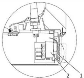
8570
natural_image
Cross-sectional technical drawing of a mechanical assembly (no visible text or labels)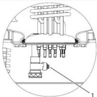
natural_image
Technical diagram of a mechanical assembly with labeled component 1 (no text or symbols present)D0000038572
3 kW 789 2/N/PE \~ 400 V
4 kW 7 8 9 2/N/PE \~ 400 V
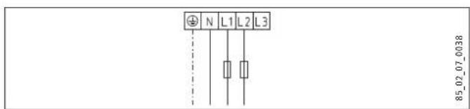
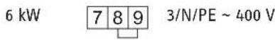
6 kW 7 8 9 3/N/PE \~ 400 V

line
| X | Series 1 | Series 2 | Series 3 | Series 4 | Series 5 | |---|---|---|---|---|---| | 30 | 2.8 | 1.2 | 0.8 | 0.6 | 0.4 | | 50 | 4.5 | 2.1 | 1.4 | 1.0 | 0.6 | | 80 | 7.1 | 3.5 | 2.3 | 1.8 | 1.0 | | 100 | 8.9 | 4.4 | 3.0 | 2.3 | 1.4 | | 120 | 10.6 | 5.2 | 3.6 | 2.7 | 1.7 | | 150 | 13.2 | 6.4 | 4.5 | 3.3 | 2.2 |X Nenninhalt [I]
Y Dauer [h]
1 1 kW
2 2 kW
3 3 kW
4 4 kW
5 6 kW
- General information 16
1.1 Safety instructions 16
1.2 Other symbols in this documentation 16
1.3 Units of measurement 16 - Safety 16
2.1 Intended use 16
2.2 General safety instructions 16
2.3 Test symbols 17 - Appliance description 17
3.1 Frost protection 17 - Settings 17
- Cleaning, care and maintenance 17
- Troubleshooting 18
INSTALLATION
- Safety 18
7.1 General safety instructions 18
7.2 Instructions, standards and regulations ____ 18
- Appliance description 18
8.1 Standard delivery 18
8.2 Accessories 18
- Preparations 18
9.1 Installation site 18
9.2 Fitting the wall mounting bracket 18
9.3 Preparing the connecting cables 19
- Installation 19
10.1 Water connection 19
10.2 Appliance installation 19
10.3 Power supply 20
- Commissioning 20
11.1 Commissioning 20
11.2 Recommissioning 20
-
Settings 21
-
Shutting down 21
-
Troubleshooting 21
-
Maintenance 22
15.1 Checking the safety valve 22
15.2 Draining the appliance ____ 22
15.3 Checking / replacing the signal anode ____ 22
15.4 Descaling 22
15.5 Anti-corrosion protection 22
- Specification 23
16.1 Dimensions and connections 23
16.2 Wiring diagrams and terminals 24
16.3 Heat-up diagram 25
16.4 Fault conditions 25
16.5 Details on energy consumption 25
16.6 Data table 26
GUARANTEE
ENVIRONMENT AND RECYCLING
SPECIAL INFORMATION
- The appliance may be used by children aged 3 and up and persons with reduced physical, sensory or mental capabilities or a lack of experience and know-how, provided that they are supervised or they have been instructed on how to use the appliance safely and have understood the resulting risks. aged 3 to 8 years are only allowed to operate the tap connected to the appliance. Children must never play with the appliance. Children must never clean the appliance or perform user maintenance unless they are supervised.
- The connection to the power supply is only permissible as a permanent connection in conjunction with the removable cable grommet. Ensure the appliance can be separated from the power supply by an isolator that disconnects all poles with at least 3 mm contact separation.
- Secure the appliance as described in chapters "Installation / Preparations" and "Installation / Installation / Appliance installation".
- Observe the minimum and maximum water inlet pressure (see chapter "Installation /Specification / Data table").
- Drain the appliance as described in the chapter "Installation / Maintenance / Draining the appliance".
- Install a residual current device (RCD).
Sealed unvented operating mode:
- The appliance is under pressure. During the heat-up process, expansion water will drip from the safety valve.
- Regularly activate the safety valve to prevent it from becoming blocked, e.g. by limescale deposits.
- Install a type-tested safety valve in the cold water supply line. Please note that, depending on the static pressure, you may also need a pressure reducing valve.
- Size the drain so that water can drain off unimpeded when the safety valve is fully opened.
- Fit the discharge pipe of the safety valve with a constant downward slope and in a room free from the risk of frost.
- The safety valve discharge aperture must remain open to the atmosphere.
OPERATION
1. General information
The chapter "Operation" is intended for appliance users and qualified contractors.
The chapter "Installation" is intended for qualified contractors.

Note
Read these instructions carefully before using the appliance and retain them for future reference.
Pass on the instructions to a new user if required.
1.1 Safety instructions
1.1.1 Structure of safety instructions

KEYWORD Type of risk
Here, possible consequences are listed that may result from failure to observe the safety instructions.
▶ Steps to prevent the risk are listed.
1.1.2 Symbols, type of risk
Symbol Type of risk

Injury

Electrocution

Burns
(burns, scalding)
1.1.3 Keywords
KEYWORD Meaning
| DANGER | Failure to observe this information will result in serious injury or death. |
| WARNING | Failure to observe this information may result in serious injury or death. |
| CAUTION | Failure to observe this information may result in non-serious or minor injury. |
1.2 Other symbols in this documentation

Note
General information is identified by the symbol shown on the left.
▶ Read these texts carefully.
Symbol Meaning

Material losses
(appliance, consequential and environmental losses)

Appliance disposal
This symbol indicates that you have to do something. The action you need to take is described step by step.
1.3 Units of measurement

Note
All measurements are given in mm unless stated otherwise.
2. Safety
2.1 Intended use
This appliance is designed to heat DHW. The appliance can supply one - or, in sealed unvented (pressurised) mode - several draw-off points.
This appliance is intended for domestic use. It can be used safely by untrained persons. The appliance can also be used in a non-domestic environment, e.g. in a small business, as long as it is used in the same way.
Any other use beyond that described shall be deemed inappropriate. Using the appliance for heating fluids other than water or for water supplemented with chemicals, such as brine, is also deemed inappropriate.
Observation of these instructions and of instructions for any accessories used is also part of the correct use of this appliance.
2.2 General safety instructions

WARNING Burns
During operation, the valve and safety assembly can reach temperatures in excess of 60 °C.
There is a risk of scalding at outlet temperatures in excess of 43 °C.

WARNING Injury
The appliance may be used by children aged 3 and up and persons with reduced physical, sensory or mental capabilities or a lack of experience and know-how, provided that they are supervised or they have been instructed on how to use the appliance safely and have understood the resulting risks. aged 3 to 8 years are only allowed to operate the tap connected to the appliance. Children must never play with the appliance. Children must never clean the appliance or perform user maintenance unless they are supervised.

Material losses
Protect the water lines and the safety assembly against frost.

Note
Sealed unvented operating mode: The appliance is under pressure. During the heat-up process, expansion water will drip from the safety valve.
▶ If water continues to drip when heating is completed, please inform your qualified contractor. Open vented operating mode: Whenever water is heated up, expansion water will drip from the spout.
2.3 Test symbols
See type plate on the appliance.
3. Appliance description
The appliance heats domestic hot water electrically, in line with the connected heating output. You can adjust the temperature using the temperature selector. Subject to the power supply, the water is automatically heated to the required temperature. The currently available heat content is displayed.
The appliance is suitable for both open vented (non-pressurised) and sealed unvented (pressurised) operation.
The internal steel cylinder is coated in special directly applied "anticor®" enamel and equipped with a signal anode. The anode with consumption indicator protects the cylinder interior from corrosion.
3.1 Frost protection
The appliance is also protected against frost on the temperature setting "cold", as long as the power supply is guaranteed. The appliance switches on in good time and heats the water. The appliance does not protect the water supply lines and the safety assembly against frost.
4. Settings
The temperature can be freely adjusted.
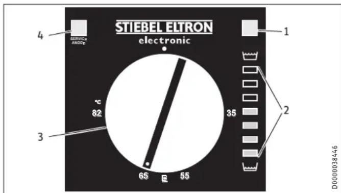
1 ON/OFF indicator
2 Heat content indicator
3 Temperature selector
4 SERVICE ANODE indicator
- Cold
E Recommended energy saving position, low scaling, 60 °C
82 °C Maximum temperature setting
Depending on the system, the actual temperatures may vary from the set value.
SERVICE ANODE indicator
Sealed unvented operating mode:

Material losses
Sealed unvented operating mode:
▶ Notify your qualified contractor if the SERVICE ANODE indicator illuminates.
Open vented operating mode:

Note
In open vented operation, the SERVICE ANODE indicator has no function.
Check the protective anode after the first 2 years of use and replace if necessary.
ON/OFF indicator
The ON/OFF indicator illuminates when water is being heated.
Heat content indicator
The display shows the currently available amount of mixed water at 40 °C, with a cold water temperature of 15 °C and a temperature setting of 65 °C. The number of lights indicates the minimum available volume of mixed water at 40 °C.
This enables you to match the temperature setting to your draw-off pattern to ensure optimum efficiency and save energy. We recommend you initially set the temperature to 65 °C . If more than one indicator remains illuminated when your maximum draw-off volume is reached you can lower the set temperature.
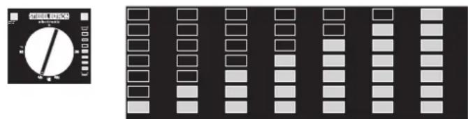
| SH 30 S | 10 | 20 | 30 | 40 | 50 | 60 | 75 |
| SH 50 S | 13 | 30 | 45 | 65 | 80 | 100 | 125 |
| SH 80 S | 20 | 50 | 75 | 100 | 130 | 160 | 200 |
| SH 100 S | 25 | 60 | 90 | 130 | 160 | 200 | 250 |
| SH 120 S | 30 | 70 | 110 | 155 | 195 | 235 | 300 |
| SH 150 S | 40 | 90 | 135 | 190 | 240 | 295 | 370 |
| DHW demand, mixed water volume 40 °C | |
| Bath | 120-150 |
| Shower | 30-50 |
| Hand washing | 2-5 |
5. Cleaning, care and maintenance
▶ Have the electrical safety of the appliance and the function of the safety assembly regularly checked by a qualified contractor.
The signal anode must be replaced by the qualified contractor as soon as the SERVICE ANODE indicator illuminates (see chapter "Maintenance / Replacing the signal anode").
▶ Never use abrasive or corrosive cleaning agents. A damp cloth is sufficient for cleaning the appliance.
Scaling
▶ Almost every type of water will deposit lime at high temperatures. This settles inside the appliance and affects both the performance and service life. The heating elements must therefore be descaled from time to time. A qualified contractor who knows the local water quality will tell you when the next service is due.
▶ Check the taps/valves regularly. You can remove limescale deposits at the spouts using commercially available descaling agents.
▶ Regularly activate the safety valve to prevent it from becoming blocked, e.g. by limescale deposits.
- Troubleshooting
| Problem Cause Remedy | ||
| The water does not heat up. | There is no power. Check the fuses/MCBs in your fuse box. | |
| The flow rate is low. | The aerator in the valve or the shower head is scaled up or contaminated. | Clean and/or descale the aerator or shower head. |
| SERVICE ANODE indicator illuminates. | The signal anode needs replacing. | Notify your qualified contractor. |
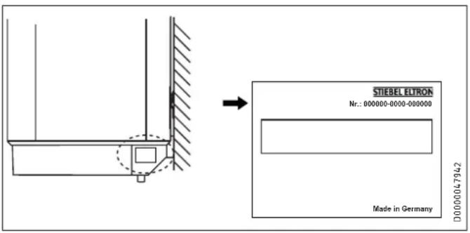
If you cannot remedy the fault, notify your qualified contractor. To facilitate and speed up your enquiry, please provide the serial number from the type plate (000000-0000-000000):
INSTALLATION
7. Safety
Only a qualified contractor should carry out installation, commissioning, maintenance and repair of the appliance.
7.1 General safety instructions
We guarantee trouble-free function and operational reliability only if original accessories and spare parts intended for the appliance are used.
7.2 Instructions, standards and regulations

Note
Observe all applicable national and regional regulations and instructions.
8. Appliance description
8.1 Standard delivery
The following are delivered with the appliance:
- Wall mounting bracket (2 pce for appliances with 120 l and 150 l nominal capacity)
- Spacers 5 mm (2 pce at the top / 2 pce at the bottom; for appliances with 120 l and 150 l, 4 pce at the top / 4 pce at the bottom)
Caps (2 pce)
- Installation template
8.2 Accessories
Required accessories
Various safety assemblies are available for sealed unvented (pressure-tested) operation, depending on the static pressure. These type-tested safety assemblies protect the appliance against impermissible excess pressure.
Further accessories
Taps are available as accessories for open vented operation.
9. Preparations
9.1 Installation site
The appliance is designed for installation on a solid wall. Ensure the wall offers adequate load bearing capacity.
Always install the appliance vertically in a room free from the risk of frost and near the draw-off point.
9.2 Fitting the wall mounting bracket
▶ You can use the installation template to transfer the dimensions to the wall.
Drill the holes and secure the wall mounting bracket with screws and rawl plugs. Select fixing materials in accordance with the wall construction/condition.
You can compensate for unevenness in the wall with the spacers provided.
Appliances with a nominal capacity of 120 l or 150 l require 2 wall mounting brackets.
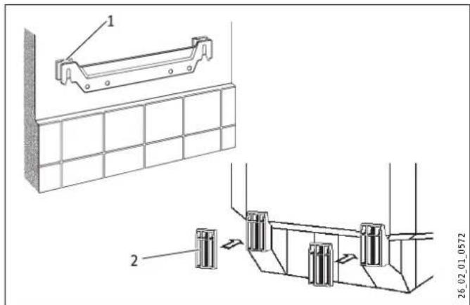
1 Upper spacer
2 Lower spacer
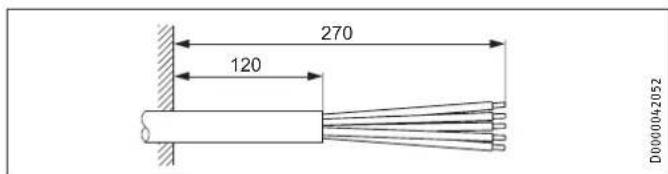
9.3 Preparing the connecting cables
10. Installation
10.1 Water connection

Material losses
Carry out all water connection and installation work in accordance with regulations.
For sealed unvented (pressurised) operation, operate the appliance only with pressure-tested taps. For open vented (non-pressurised) operation, use non-pressurised taps. Connect the hydraulic connections with flat gaskets.
10.1.1 Permissible materials

Material losses
When using plastic pipework, observe the manufacturer's data and the chapter "Specification / Fault conditions". The temperature setting can be limited by the qualified contractor (see chapter "Settings / Limiting the temperature selection").
Cold water line
Galvanised steel, stainless steel, copper and plastic are approved materials.
A safety valve is required.
DHW line
Stainless steel, copper and plastic pipework are approved materials.
10.1.2 Sealed unvented (pressure-tested) for supplying several draw-off points
The max. permissible pressure must not be exceeded (see chapter "Specification / Data table" and cylinder specification).
▶ Install a type-tested safety valve in the cold water supply line. Please note that, depending on the static pressure, you may also need a pressure reducing valve.
▶ Size the drain so that water can drain off unimpeded when the safety valve is fully opened.
▶ Fit the discharge pipe of the safety valve with a constant downward slope and in a room free from the risk of frost.
▶ The safety valve discharge aperture must remain open to the atmosphere.
10.1.3 Open (non-pressurised) for supplying one draw-off point

Note
Never shut off the outlet and pivoting spout.
Do not use an aerator.
10.2 Appliance installation
Appliances with a nominal capacity of 120 l or 150 l require 2 people for installation.
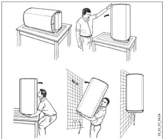
natural_image
Illustration of a person installing or adjusting a large cylindrical device on a workbench, with no visible text or symbols.
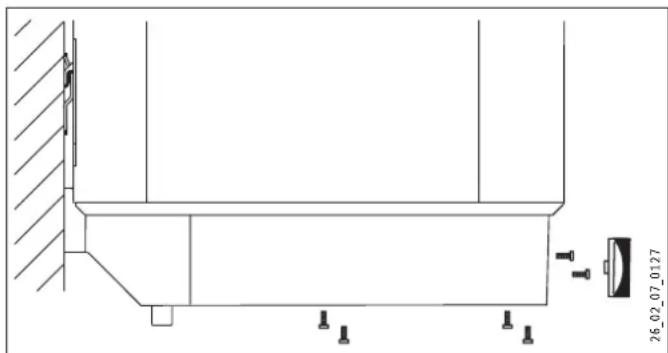
natural_image
Technical diagram of a structural support frame assembly (no text or symbols)1 Cap
▶ Fit the caps.
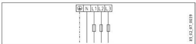
10.3 Power supply

WARNING Electrocution
Carry out all electrical connection and installation work in accordance with relevant regulations.
Before any work on the appliance, disconnect all poles from the power supply.

WARNING Electrocution
The connection to the power supply is only permissible as a permanent connection in conjunction with the removable cable grommet. Ensure the appliance can be separated from the power supply by an isolator that disconnects all poles with at least 3 mm contact separation.

WARNING Electrocution
Ensure that the appliance is earthed.

Material losses
Install a residual current device (RCD).

Material losses
Observe the type plate. The specified voltage must match the mains voltage.
natural_image
Technical line drawing of a mechanical assembly with mounting holes and a scale indicator (no text or symbols)▶ Pull off the temperature selector.
▶ Undo the screws.
▶ Remove the lower cap.
▶ Pull the cable grommet out downwards while pressing on the locking hooks.
▶ Push the cable grommet over the connecting cable and snap the cable grommet back in place.
- Connect the required load in accordance with the wiring diagrams (see chapter "Specification / Wiring diagrams and terminals").
▶ Fit the lower cap.
▶ Insert the screws.
▶ Push on the temperature selector.
- Tick the selected connected load and voltage on the type plate with a ballpoint pen.
Sealed unvented (pressure-tested) operation
- Connect the safety assembly to the appliance by screwing the pipes onto the appliance.
Open vented (non-pressurised) operation
▶ Connect the appliance to the tap.
11. Commissioning
11.1 Commissioning
▶ Open a draw-off point until the appliance has filled up and the pipework is free of air.
▶ Adjust the flow rate. For this, observe the maximum permissible flow rate with a fully opened tap (see chapter "Specification / Data table").
▶ Sealed unvented (pressure-tested) operation: If necessary reduce the flow rate at the butterfly valve of the safety assembly.
▶ Turn the temperature selector to maximum.
▶ Switch the mains power ON.
▶ Check the function of the appliance. Ensure that the thermostat switches off.
▶ Sealed unvented (pressure-tested) operation: Check the function of the safety assembly.
11.1.1 Appliance handover
Explain the function of the appliance and safety assembly to users and familiarise them with their operation.
▶ Make users aware of potential dangers, especially the risk of scalding.
▶ Hand over these instructions.
11.2 Recommissioning
See chapter "Commissioning".
12. Settings
Limiting the temperature selection
You can adjust the temperature selection limit beneath the temperature selector.
▶ Set the temperature selector to "cold" and isolate the appliance from the power supply.
▶ Remove the temperature selector.
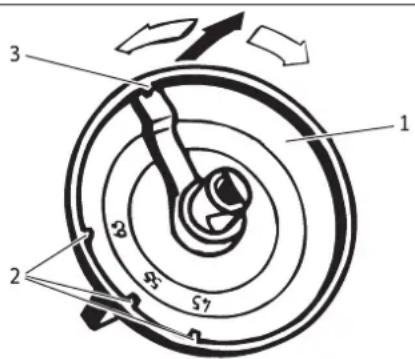
26_02_07_0099
1 Temperature selector
2 Temperature selection limit at 45 °C, 55 °C, 65 °C
3 Factory setting 85 °C
▶ Adjust the temperature selection limit.
▶ Replace the temperature selector.
13. Shutting down
▶ Disconnect the appliance from the mains at the MCB/fuse in the fuse box.
- Drain the appliance (see chapter "Maintenance / Draining the appliance").
14. Troubleshooting

Note
At temperatures below -15 ^ the high limit safety cut-out may respond. The appliance may be subjected to these temperatures during storage or transport.
| Fault Cause | Remedy | |
| The water does not heat up. | The high limit safety cut-out has responded because the controller is faulty. | Remedy the cause of the fault. Replace the controller-limiter combination. |
| The high limit safety cut-out has responded because the temperature has fallen below -15 °C. | Press the reset button (see diagram). | |
| The flanged immersion heater is faulty. | Replace the flanged immersion heater. | |
| The safety valve drips when heating is switched off. | The valve seat is contaminated. | Clean the valve seat. |
| SERVICE ANODE indicator illuminates. | The signal anode has been consumed. | Replace the signal anode. |
Reset key, high limit safety cut-out
The reset button is located behind the temperature selector.
▶ Pull off the temperature selector.
1 Reset key, high limit safety cut-out
2 Controller/limiter combination
15. Maintenance

WARNING Electrocution
Carry out all electrical connection and installation work in accordance with relevant regulations.
Before any work on the appliance, disconnect all poles of the appliance from the power supply.
For some maintenance work, the lower cap must be removed.
If you need to drain the appliance, observe chapter "Draining the appliance".
Note the insertion depths of the controller-limiter combination (see chapter "Specification / Dimensions and connections").
15.1 Checking the safety valve
▶ Check the safety valve regularly.
15.2 Draining the appliance

WARNING Burns
Hot water may escape during the draining process.
If is necessary to drain the cylinder for maintenance or to protect the whole installation from frost, proceed as follows:
▶ Close the shut-off valve in the cold water feed line.
▶ Open the hot water taps on all draw-off points.
natural_image
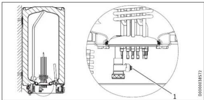
Technical diagram of a mechanical assembly with cross-sectional and top views (no text or symbols)1 Drain valve with hose connection G 3/4
▶ Undo the cap of the "drain" connection.
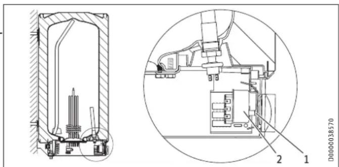
15.3 Checking / replacing the signal anode
▶ If the SERVICE ANODE indicator illuminates, check the signal anode and replace if necessary.
SH 30 S (M 8)
▶ Removed the flanged immersion heater to replace the signal anode.
SH 50 - 150 S (G ^3/4 )
▶ You can replace the anode without removing the flanged immersion heater.
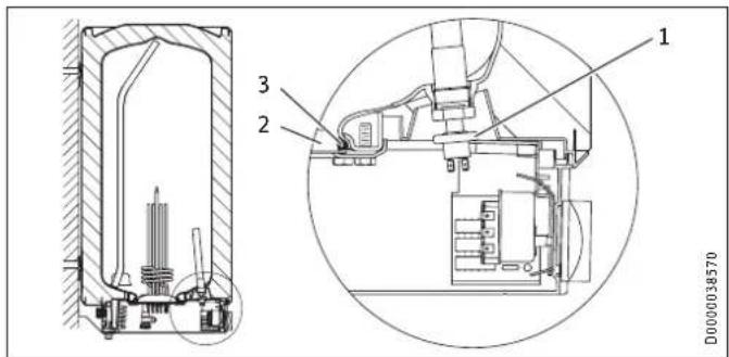
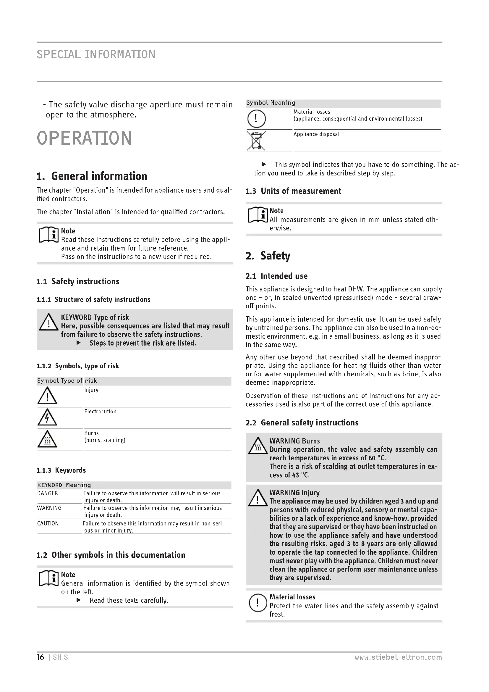
1 Pressure switch for signal anode
2 Flange plate
3 Seal ring
▶ When replacing the anode, take great care to fit the pressure switch on tightly.
Torque: 1 ^+0.5 Nm (tighten by hand)
15.4 Descaling
▶ Open vented operating mode: If you are using a mixer tap with a hand shower, regular descaling will be necessary.
▶ Only descale the flange after disassembly and never treat the cylinder surface or signal anode with descaling agents.
15.5 Anti-corrosion protection
When carrying out service work, ensure that the anti-corrosion protection on the insulating plate is not damaged or removed. Reinsert the anti-corrosion protection correctly after replacement.
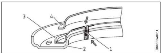
1 Anti-corrosion protection (390 Ω)
2 Pressure plate
3 Insulating plate
4 Flanged immersion heater
16. Specification
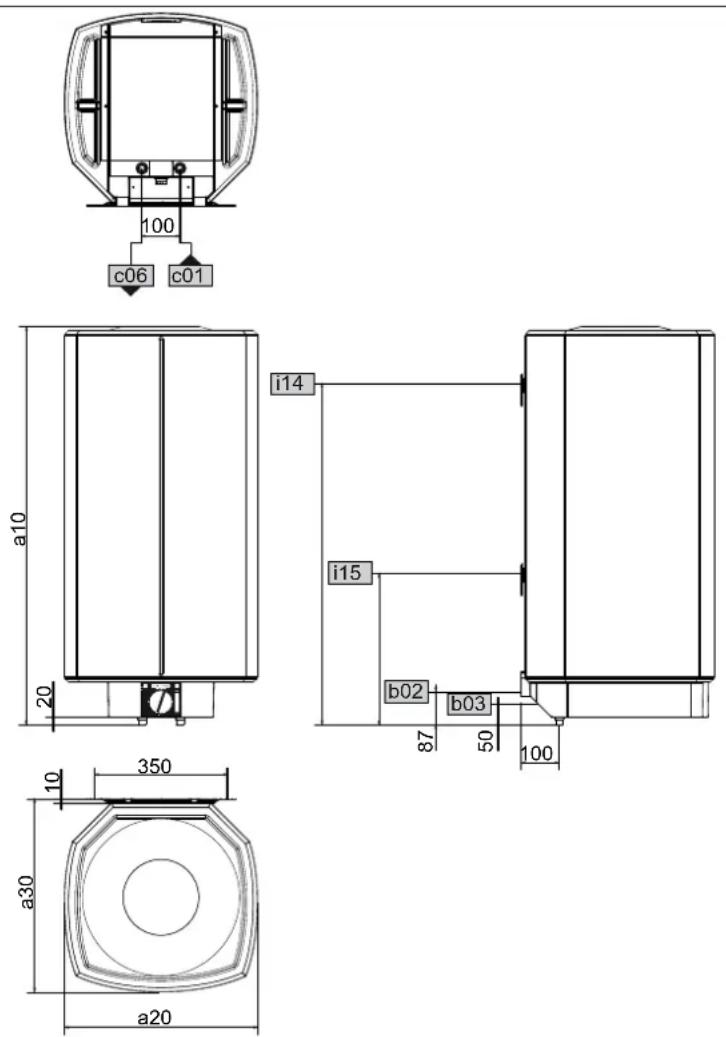
16.1 Dimensions and connections
D0000024799
| SH 30 S SH 50 S SH 80 S SH 100 S SH 120 S SH 150 S | |||||||||
| a10 | Appliance | Height | mm | 770 | 740 | 1050 | 1050 | 1210 | 1445 |
| a20 | Appliance | Width | mm | 410 | 510 | 510 | 510 | 510 | 510 |
| a30 | Appliance | Depth | mm | 420 | 510 | 510 | 510 | 510 | 510 |
| b02 | Entry electrical cables I | PG 21 | PG 21 | PG 21 | PG 21 | PG 21 | PG 21 | ||
| b03 | Entry electrical cables II | ||||||||
| c01 | Cold water inlet | Male thread | G 1/2 A | G 1/2 A | G 1/2 A | G 1/2 A | G 1/2 A | G 1/2 A | |
| c06 | DHW outlet | Male thread | G 1/2 A | G 1/2 A | G 1/2 A | G 1/2 A | G 1/2 A | G 1/2 A | |
| i14 | Wall mounting bracket I | Height | mm | 700 | 600 | 900 | 900 | 900 | 1100 |
| Max. ∅ fixing screw | mm | 12 | 12 | 12 | 12 | 12 | 12 | ||
| i15 | Wall mounting bracket II | Height | mm | 300 | 300 | ||||
| Max. ∅ fixing screw | mm | 12 | 12 | ||||||
Controller-limiter combination immersion depths
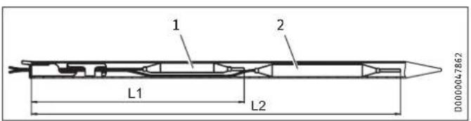
1 Limiter sensor
2 Controller sensor
| SH30 S | SH50 S | SH80 S | SH100 S | SH120 S | SH150 S | ||||||||
| L1 | Immersion depth | mm | 260 | 260 | 240 | 240 | 240 | 260 | |||||
| L2 | Immersion depth | mm | 380 | 380 | 350 | 350 | 350 | 380 | |||||
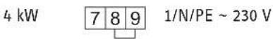
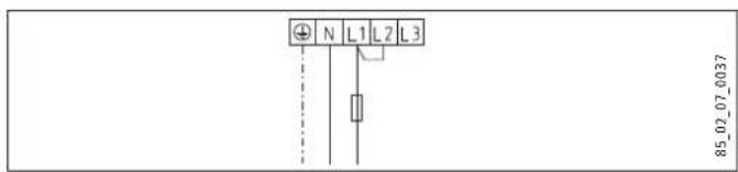
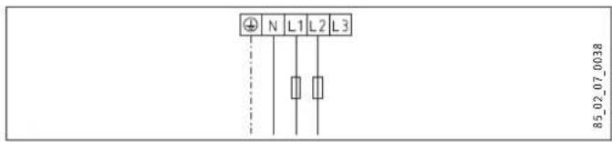
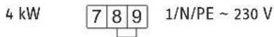
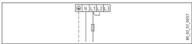
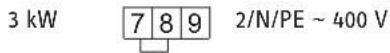
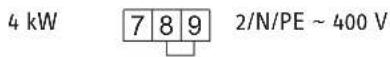
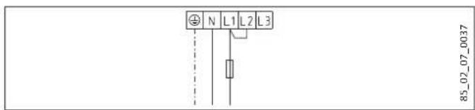
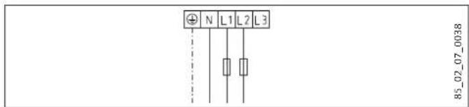
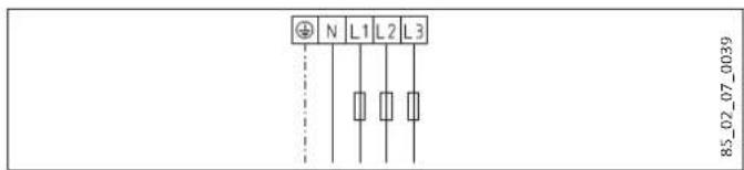
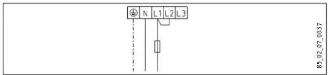
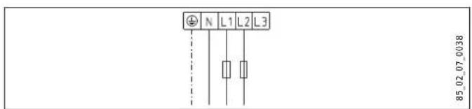
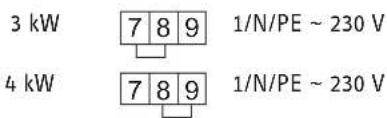
16.2 Wiring diagrams and terminals
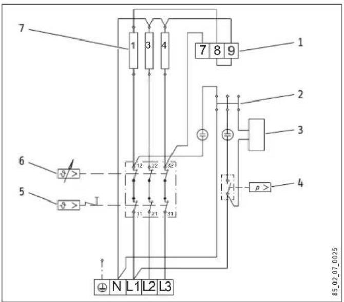
1 Terminal for output changeover
2 Plug-in distributor for N conductor
3 Heat content indicator
4 Pressure switch for signal anode
5 High limit safety cut-out
6 Temperature controller
7 Heating element, 2 kW \~ 230 V each
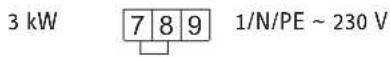
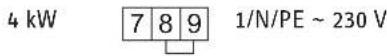
1 kW 789 1/N/PE \~ 230 V
2 kW 789 1/N/PE \~ 230 V
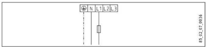
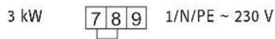
3 kW 789 1/N/PE \~ 230 V
4 kW 7 8 9 1/N/PE \~ 230 V
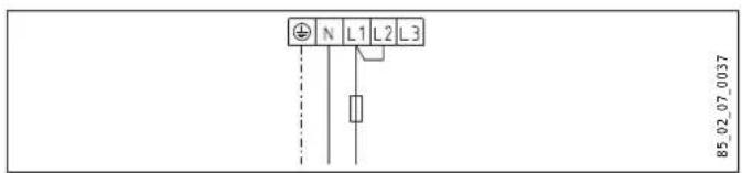
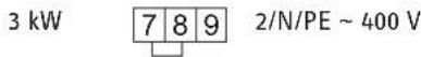
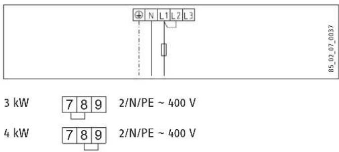
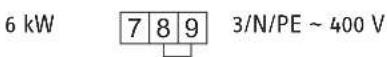
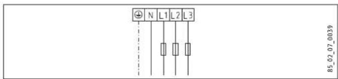
3 kW 789 2/N/PE \~ 400 V
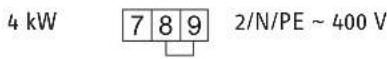
4 kW 7 8 9 2/N/PE \~ 400 V
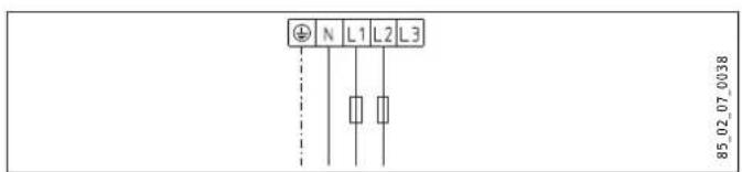
6 kW 7 8 9 3/N/PE \~ 400 V

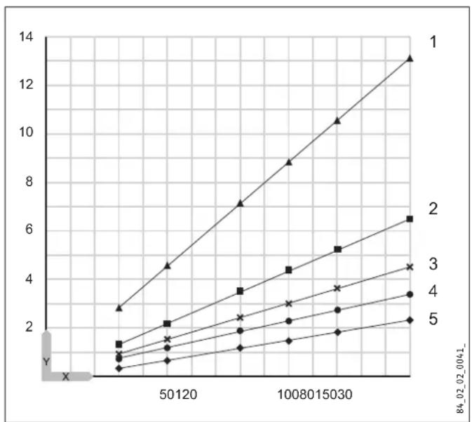
16.3 Heat-up diagram
The heat-up time depends on the cylinder capacity, cold water inlet temperature and heating output.
Diagram with 15 °C cold water temperature:
Set temperature setting 82 °C
line
| X | Series 1 | Series 2 | Series 3 | Series 4 | Series 5 | |---|---|---|---|---|---| | 0 | 2.8 | 1.2 | 0.8 | 0.6 | 0.4 | | 50120 | 4.5 | 2.1 | 1.5 | 1.2 | 0.8 | | 10080 | 7.0 | 3.5 | 2.5 | 2.0 | 1.2 | | 15030 | 9.0 | 4.5 | 3.5 | 3.0 | 1.8 | | 20080 | 10.5 | 5.3 | 4.5 | 3.8 | 2.2 | | 25030 | 13.0 | 6.5 | 4.5 | 3.5 | 2.5 | The chart displays a single data series with X-axis values ranging from 0 to over 1200 and Y-axis values from 0 to over 14. The legend is labeled with numbers 1 through 5 in the top row.X Nominal capacity [I]
Y Duration [h]
1 1 kW
2 2 kW
3 3 kW
4 4 kW
5 6 kW
16.4 Fault conditions
In the event of a fault, temperatures of up to 95 °C at 0.6 MPa can occur.
16.5 Details on energy consumption
Product datasheet: Conventional water heaters to regulation (EU) no. 812/2013 and 814/2013
| SH 30 S | SH 50 S | SH 80 S | SH 100 S | SH 120 S | SH 150 S | ||
| 073047 | 073048 | 073049 | 073050 | 073051 | 073052 | ||
| Manufacturer | STIEBEL ELTRON | STIEBEL ELTRON | STIEBEL ELTRON | STIEBEL ELTRON | STIEBEL ELTRON | STIEBEL ELTRON | |
| Load profile | S | M | M | L | L | XL | |
| Energy efficiency class | B | C | C | C | C | C | |
| Energy conversion efficiency | % | 36 | 38 | 37 | 38 | 38 | 39 |
| Annual power consumption | kWh | 518 | 1349 | 1381 | 2666 | 2705 | 4321 |
| Default temperature setting | °C | 60 | 60 | 60 | 60 | 60 | 60 |
| Sound power level | dB(A) | 15 | 15 | 15 | 15 | 15 | 15 |
| Option for exclusive operation during off-peak periods | - | - | - | - | - | - | |
| Smart function | - | - | - | - | - | - | |
| Daily power consumption | kWh | 2.437 | 6.233 | 6.419 | 12.288 | 12.516 | 19.859 |
| Amount of mixed water 40 °C | l | 50 | 80 | 122 | 133 | 182 | 229 |
16.6 Data table
| SH 30 S SH 50 S SH 80 S SH 100 S SH 120 S SH 150 S | |||||||
| 073047 | 073048 | 073049 | 073050 | 073051 | 073052 | ||
| Hydraulic data | |||||||
| Nominal capacity | l | 30 | 50 | 80 | 100 | 120 | 150 |
| Amount of mixed water 40 °C (15 °C/65 °C) | l | 59 | 97 | 159 | 198 | 235 | 292 |
| Electrical data | |||||||
| Connected load ~ 230 V | kW | 1-4 | 1-4 | 1-4 | 1-4 | 1-4 | 1-4 |
| Connected load ~ 400 V | kW | 3-6 | 3-6 | 3-6 | 3-6 | 3-6 | 3-6 |
| Phases | 1/N/PE, 2/N/PE, 3/N/PE | 1/N/PE, 2/N/PE, 3/N/PE | 1/N/PE, 2/N/PE, 3/N/PE | 1/N/PE, 2/N/PE, 3/N/PE | 1/N/PE, 2/N/PE, 3/N/PE | 1/N/PE, 2/N/PE, 3/N/PE | |
| Rated voltage | V | 230/400 | 230/400 | 230/400 | 230/400 | 230/400 | 230/400 |
| Frequency | Hz | 50 | 50 | 50 | 50 | 50 | 50 |
| Single circuit operating mode | X | X | X | X | X | X | |
| Application limits | |||||||
| Temperature setting range | °C | 35-82 | 35-82 | 35-82 | 35-82 | 35-82 | 35-82 |
| Max. permissible pressure | MPa | 0.6 | 0.6 | 0.6 | 0.6 | 0.6 | 0.6 |
| Test pressure | MPa | 0.78 | 0.78 | 0.78 | 0.78 | 0.78 | 0.78 |
| Max. permissible temperature | °C | 95 | 95 | 95 | 95 | 95 | 95 |
| Max. flow rate | l/min | 18 | 18 | 18 | 18 | 18 | 18 |
| Min. water inlet pressure | MPa | 0.1 | 0.1 | 0.1 | 0.1 | 0.1 | 0.1 |
| Max. water inlet pressure | MPa | 0.6 | 0.6 | 0.6 | 0.6 | 0.6 | 0.6 |
| Min./max. conductivity, drinking water | μS/cm | 100-1500 | 100-1500 | 100-1500 | 100-1500 | 100-1500 | 100-1500 |
| Energy data | |||||||
| Standby energy consumption/24 h at 65 °C | kWh | 0.46 | 0.54 | 0.67 | 0.86 | 0.99 | 1.1 |
| Energy efficiency category | B | C | C | C | C | C | |
| Versions | |||||||
| IP rating | IP25 | IP25 | IP25 | IP25 | IP25 | IP25 | |
| Sealed unvented type | X | X | X | X | X | X | |
| Open vented type | X | X | X | X | X | X | |
| Colour | White | White | White | White | White | White | |
| Dimensions | |||||||
| Height | mm | 770 | 740 | 1050 | 1050 | 1210 | 1445 |
| Width | mm | 410 | 510 | 510 | 510 | 510 | 510 |
| Depth | mm | 420 | 510 | 510 | 510 | 510 | 510 |
| Weights | |||||||
| Weight, full | kg | 53 | 78 | 118 | 140 | 165 | 203 |
| Weight, empty | kg | 23.1 | 28 | 38 | 40.8 | 45.5 | 53.3 |
Guarantee
The guarantee conditions of our German companies do not apply to appliances acquired outside of Germany. In countries where our subsidiaries sell our products a guarantee can only be issued by those subsidiaries. Such guarantee is only granted if the subsidiary has issued its own terms of guarantee. No other guarantee will be granted.
We shall not provide any guarantee for appliances acquired in countries where we have no subsidiary to sell our products. This will not affect warranties issued by any importers.
Environment and recycling
▶ Dispose of the appliances and materials after use in accordance with national regulations.
If a crossed-out waste bin is pictured on the appliance, take the appliance to your local waste and recycling centre or nearest retail take-back point for reuse and recycling.
This document is made of recyclable paper.
- Dispose of the document at the end of the appliance's life cycle in accordance with national regulations.
REMARQUES PARTICULIÈRES
UTILISATION
natural_image
Illustration of a person installing or adjusting a cylindrical device on a table, with no visible text or symbols.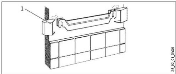
natural_image
Technical line drawing of a structural support bracket assembly (no text or symbols)1 Cache
▶ Montez les caches.
natural_image
Technical line drawing of a mechanical assembly with mounting holes and a vertical component (no text or symbols)natural_image
Technical diagram of a mechanical assembly with cross-sectional and top views (no text or labels)3 kW 789 1/N/PE \~ 230 V
4 kW 789 1/N/PE \~ 230 V

3 kW 789 2/N/PE \~ 400 V
4 kW 7 8 9 2/N/PE \~ 400 V

6 kW 7 8 9 3/N/PE \~ 400 V

16.3 Courbe de chauffe
line
| X | Series 1 | Series 2 | Series 3 | Series 4 | Series 5 | |---|---|---|---|---|---| | 0 | 2.8 | 1.2 | 0.8 | 0.6 | 0.4 | | 50120 | 4.5 | 2.1 | 1.5 | 1.2 | 0.7 | | 10080 | 7.0 | 3.5 | 2.5 | 2.0 | 1.2 | | 15030 | 9.0 | 4.5 | 3.2 | 2.8 | 1.6 | | 20080 | 10.5 | 5.3 | 3.8 | 3.4 | 2.0 | | 25030 | 13.0 | 6.5 | 4.5 | 3.8 | 2.4 | The chart displays a linear trend with X-axis labeled as 'X' and Y-axis labeled as 'Y'. The legend is labeled '1', '2', '3', '4', and '5'. The values for each series are explicitly labeled on the chart.X Capacité nominale [I]
Y Durée [I]
1 1 kW
2 2 kW
3 3 kW
4 4 kW
5 6 kW
WAARSCHUWING verbranding
natural_image
Abstract pattern of black and white rectangular blocks arranged in vertical columns (no text or symbols)| SH 30 S | 1 | 10 | 20 | 30 | 40 | 50 | 60 | 75 |
| SH 50 S | 1 | 13 | 30 | 45 | 65 | 80 | 100 | 125 |
| SH 80 S | 1 | 20 | 50 | 75 | 100 | 130 | 160 | 200 |
| SH 100 S | 1 | 25 | 60 | 90 | 130 | 160 | 200 | 250 |
| SH 120 S | 1 | 30 | 70 | 110 | 155 | 195 | 235 | 300 |
| SH 150 S | 1 | 40 | 90 | 135 | 190 | 240 | 295 | 370 |
| Warmwaterbehoefte, mengwatervolume 40 °C | |
| Baden | 120-150 |
| Douchen | 30-50 |
| Handen wassen | 2-5 |
natural_image
Illustration of a person installing or adjusting a large cylindrical device on a workbench, with no visible text or symbols.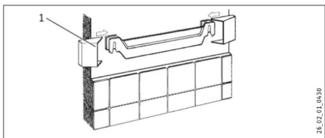
1 Afdekkap
▶ Monteer de afdekkappen.
natural_image
Technical line drawing of a mechanical assembly with mounting holes and a scale (no text or symbols)WAARSCHUWING verbranding
natural_image
Cross-sectional diagram of a mechanical assembly with no visible text or symbols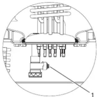
natural_image
Technical diagram of a mechanical assembly with labeled component 1 (no text or symbols present)D0000038572

line
| X | Y (Series 1) | Y (Series 2) | Y (Series 3) | Y (Series 4) | Y (Series 5) | |---|---|---|---|---|---| | 0 | 2.8 | 1.2 | 0.8 | 0.6 | 0.4 | | 50120 | 4.5 | 2.1 | 1.5 | 1.2 | 0.8 | | 10080 | 7.0 | 3.5 | 2.5 | 2.0 | 1.2 | | 15030 | 8.8 | 4.4 | 3.2 | 2.7 | 1.6 | | 20080 | 10.5 | 5.2 | 3.8 | 3.3 | 2.0 | | 25030 | 13.2 | 6.4 | 4.5 | 3.8 | 2.4 | The chart displays a linear trend with increasing X values from left to right along the X-axis. The Y-axis values are explicitly labeled for each data point.X Nominale inhoud [I]
Y Duur [h]
1 1 kW
2 2 kW
3 3 kW
4 4 kW
5 6 kW
15.4 Storingssituaties
natural_image
Grid of white squares on black background, no text or symbols present| SH 30 S | 1 | 10 | 20 | 30 | 40 | 50 | 60 | 75 |
| SH 50 S | 1 | 13 | 30 | 45 | 65 | 80 | 100 | 125 |
| SH 80 S | 1 | 20 | 50 | 75 | 100 | 130 | 160 | 200 |
| SH 100 S | 1 | 25 | 60 | 90 | 130 | 160 | 200 | 250 |
| SH 120 S | 1 | 30 | 70 | 110 | 155 | 195 | 235 | 300 |
| SH 150 S | 1 | 40 | 90 | 135 | 190 | 240 | 295 | 370 |
natural_image
Illustration of a person installing or adjusting a large cylindrical device on a table, with no visible text or symbols.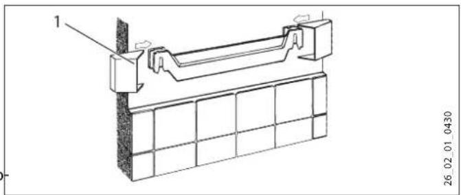
1 Защитная крышка
natural_image
Technical line drawing of a mechanical assembly with mounting holes and a scale indicator (no text or symbols)natural_image
Technical line drawing of a mechanical assembly with cross-sectional and top views (no text or symbols)3 kBt 7 8 9 1-φ./N/PE \~ 230 B 4 kBt 7 8 9 1-φ./N/PE \~ 230 B
3 kBt 7 8 9 2/N/PE \~ 400 B 4 kBt 7 8 9 2/N/PE \~ 400 B
6 kBt 7 8 9 3-φ./N/PE \~ 400 B
line
| X | Series 1 | Series 2 | Series 3 | Series 4 | Series 5 | |---|---|---|---|---|---| | 0 | 2.8 | 1.2 | 0.8 | 0.6 | 0.4 | | 50120 | 4.5 | 2.2 | 1.5 | 1.2 | 0.8 | | 10080 | 7.0 | 3.5 | 2.5 | 2.0 | 1.2 | | 15030 | 8.8 | 4.5 | 3.2 | 2.8 | 1.6 | | 20080 | 10.5 | 5.3 | 3.8 | 3.4 | 2.0 | | 25030 | 13.0 | 6.5 | 4.5 | 3.8 | 2.4 | The chart displays a single data series with values for the top row (labeled '1') and the bottom row (labeled 'X'). The bottom row contains additional numerical labels (e.g., '84_02_02_0041_) but no corresponding data series are plotted in this view.natural_image
Abstract pattern of vertical gray and white squares on black background (no text or symbols)| SH 30 S | 1 | 10 | 20 | 30 | 40 | 50 | 60 | 75 |
| SH 50 S | 1 | 13 | 30 | 45 | 65 | 80 | 100 | 125 |
| SH 80 S | 1 | 20 | 50 | 75 | 100 | 130 | 160 | 200 |
| SH 100 S | 1 | 25 | 60 | 90 | 130 | 160 | 200 | 250 |
| SH 120 S | 1 | 30 | 70 | 110 | 155 | 195 | 235 | 300 |
| SH 150 S | 1 | 40 | 90 | 135 | 190 | 240 | 295 | 370 |
natural_image
Illustration of a person installing or adjusting a large cylindrical device on a workbench, with no visible text or symbols.
natural_image
Technical line drawing of a structural support bracket assembly (no text or symbols)natural_image
Technical line drawing of a mechanical assembly with mounting holes and a vertical component (no text or symbols)natural_image
Technical line drawing of a mechanical assembly with cross-sectional and top views (no text or symbols)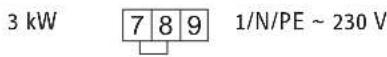
line
| X | Series 1 | Series 2 | Series 3 | Series 4 | Series 5 | |---|---|---|---|---|---| | 0 | 2.8 | 1.2 | 0.8 | 0.6 | 0.4 | | 50120 | 4.5 | 2.1 | 1.5 | 1.2 | 0.8 | | 10080 | 7.0 | 3.5 | 2.5 | 2.0 | 1.2 | | 15030 | 9.0 | 4.5 | 3.5 | 3.0 | 1.8 | | 20080 | 10.5 | 5.3 | 4.5 | 3.8 | 2.2 | | 25030 | 13.0 | 6.5 | 4.5 | 3.5 | 2.5 |natural_image
Grid of rectangular blocks on black background, no text or symbols present| SH 30 S | 1 | 10 | 20 | 30 | 40 | 50 | 60 | 75 |
| SH 50 S | 1 | 13 | 30 | 45 | 65 | 80 | 100 | 125 |
| SH 80 S | 1 | 20 | 50 | 75 | 100 | 130 | 160 | 200 |
| SH 100 S | 1 | 25 | 60 | 90 | 130 | 160 | 200 | 250 |
| SH 120 S | 1 | 30 | 70 | 110 | 155 | 195 | 235 | 300 |
| SH 150 S | 1 | 40 | 90 | 135 | 190 | 240 | 295 | 370 |
natural_image
Illustration of a person installing or adjusting a large cylindrical device on a table, with no visible text or symbols.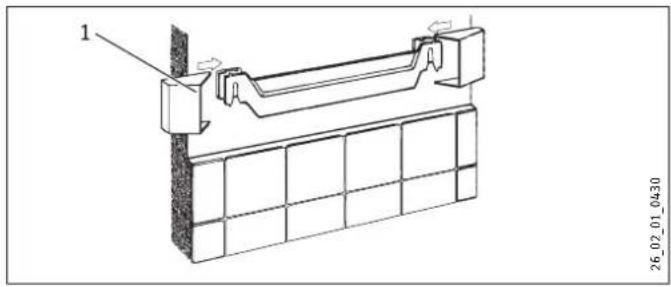
natural_image
Technical line drawing of a structural joint or bracket assembly (no text or symbols present)1 Sapka
natural_image
Technical line drawing of a mechanical assembly with mounting holes and a scale (no text or symbols)natural_image
Cross-sectional diagram of a mechanical assembly with no visible text or symbols
natural_image
Technical line drawing of a mechanical assembly with labeled parts (1 and 2), no readable text or symbols beyond labels8570
natural_image
Cross-sectional diagram of a mechanical assembly with no visible text or symbols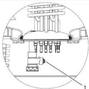
natural_image
Technical diagram of a mechanical assembly with labeled component 1 (no text or symbols present)D0000038572

line
| X | Series 1 | Series 2 | Series 3 | Series 4 | Series 5 | |---|---|---|---|---|---| | 30 | 2.8 | 1.2 | 0.8 | 0.6 | 0.4 | | 50 | 4.5 | 2.1 | 1.5 | 1.1 | 0.7 | | 80 | 7.0 | 3.5 | 2.3 | 1.8 | 1.1 | | 100 | 8.8 | 4.4 | 3.0 | 2.3 | 1.4 | | 120 | 10.6 | 5.2 | 3.6 | 2.7 | 1.7 | | 150 | 13.2 | 6.4 | 4.5 | 3.3 | 2.2 |- BESONDERE HINWEISE
- BEDIENUNG
- INSTALLATION
- Sicherheit
- Abdeckkappe
- GUARANTEE
- ENVIRONMENT AND RECYCLING
- SPECIAL INFORMATION
- Sealed unvented operating mode:
- OPERATION
- General information
- Note
- Safety instructions
- Structure of safety instructions
- KEYWORD Type of risk
- Symbols, type of risk
- Keywords
- Other symbols in this documentation
- Units of measurement
- Safety
- Intended use
- General safety instructions
- WARNING Burns
- WARNING Injury
- Material losses
- Test symbols
- Appliance description
- Frost protection
- Settings
- SERVICE ANODE indicator
- ON/OFF indicator
- Heat content indicator
- Cleaning, care and maintenance
- Scaling
- Safety
- General safety instructions
- Instructions, standards and regulations
- Appliance description
- Standard delivery
- Accessories
- Required accessories
- Further accessories
- Preparations
- Installation site
- Fitting the wall mounting bracket
- Preparing the connecting cables
- Installation
- Water connection
- Permissible materials
- Cold water line
- DHW line
- Sealed unvented (pressure-tested) for supplying several draw-off points
- Open (non-pressurised) for supplying one draw-off point
- Appliance installation
- Power supply
- WARNING Electrocution
- Sealed unvented (pressure-tested) operation
- Open vented (non-pressurised) operation
- Commissioning
- Commissioning
- Appliance handover
- Recommissioning
- Settings
- Limiting the temperature selection
- Shutting down
- Troubleshooting
- Reset key, high limit safety cut-out
- Maintenance
- Checking the safety valve
- Draining the appliance
- Checking / replacing the signal anode
- Descaling
- Anti-corrosion protection
- Specification
- Dimensions and connections
- Heat-up diagram
- Fault conditions
- Details on energy consumption
- REMARQUES PARTICULIÈRES
- UTILISATION
- Cache
- Courbe de chauffe
- WAARSCHUWING verbranding
- Afdekkap
- Storingssituaties
- Защитная крышка
Brand : STIEBEL ELTRON
Model : SH 150 S
Category : Boiler