
MHN33PD - Washing machine MAYTAG - Free user manual and instructions
Find the device manual for free MHN33PD MAYTAG in PDF.

| Product type | Commercial washing machine |
| Brand | Maytag |
| Model | MHN33PD |
| Power supply | 120 V, 60 Hz, 15 A or 20 A, AC only |
| Wash cycles | Normal, Delicates, PowerWash |
| Available temperatures | Cold, Cool, Warm, Hot |
| Adjustable wash time | 9 to 17 minutes |
| Maximum spin speed | 800 rpm (adjustable 600, 750, 800, 1000) |
| Additional options | Extra rinse, Pre-wash |
| Payment system | Coins (model PD) or debit card (model PR) |
| Door lock | Yes, automatic during cycle |
| Recommended cleaning | Monthly with bleach; clean seal and dispenser drawer |
| Safety | Grounding required; fire and electric shock instructions |
| Warranty | 7-year limited (specific parts) – see manual for details |
| Included parts | Retaining strap, water inlet hoses (2), washers (4), caps (4), tie, drain hose, flange |
| Optional accessories | Drip tray, cleaning product, storage rack, pedestal |
| Intended use | Laundromat or pay-per-use |
Frequently Asked Questions - MHN33PD MAYTAG
User questions about MHN33PD MAYTAG
0 question about this device. Answer the ones you know or ask your own.
Ask a new question about this device
Download the instructions for your Washing machine in PDF format for free! Find your manual MHN33PD - MAYTAG and take your electronic device back in hand. On this page are published all the documents necessary for the use of your device. MHN33PD by MAYTAG.
USER MANUAL MHN33PD MAYTAG
INSTALLATION INSTRUCTIONS
COMMERCIAL FRONT-LOAD WASHER
INSTRUCTIONS D'INSTALLATION
LAVEUSE COMMERCIALE À CHARGEMENT FRONTAL
Location Requirements 5
Drain System 5
Electrical Requirements. 6
INSTALLATION INSTRUCTIONS 6
Remove Transport System. 6
Connect the Inlet Hoses 7
Connect the Drain Hose 8
Secure the Drain Hose 8
Level the Washer 9
Complete Installation 9
USER&SET-UPINSTRUCTIONS 10
General User Information 10
Control Set-up Procedures 10
Start Operating Set-up. 10
WASHER CARE 14
Cleaning Your Washer. 14
Water Inlet Hoses 15
ASSISTANCE OR SERVICE 15
WARRANTY 16
TABLE DES MATIÈRES
SECURITE DE LA LAVEUSE 17
EXIGENCES D'INSTALLATION 18
ASSISTANCE OU SERVICE 31
GARANTIE 32
TABLE DE CONTENIDOS
Your safety and the safety of others are very important.
We have provided many important safety messages in this manual and on your appliance. Always read and obey all safety messages.

This is the safety alert symbol.
This symbol alerts you to potential hazards that can kill or hurt you and others.
All safety messages will follow the safety alert symbol and either the word "DANGER" or "WARNING."
These words mean:
DANGER
WARNING
You can be killed or seriously injured if you don't immediately follow instructions.
You can be killed or seriously injured if you don't follow instructions.
All safety messages will tell you what the potential hazard is, tell you how to reduce the chance of injury, and tell you what can happen if the instructions are not followed.
IMPORTANT SAFETY INSTRUCTIONS
WARNING: To reduce the risk of fire, electric shock, or injury to persons when using the washer, follow basic precautions, including the following:
Read all instructions before using the washer.
- Do not wash articles that have been previously cleaned in, washed in, soaked in, or spotted with gasoline, dry-cleaning solvents, other flammable, or explosive substances as they give off vapors that could ignite or explode.
- Do not add gasoline, dry-cleaning solvents, or other flammable, or explosive substances to the wash water. These substances give off vapors that could ignite or explode.
Under certain conditions, hydrogen gas may be produced in a hot water system that has not been used for 2 weeks or more. HYDROGEN GAS IS EXPLOSIVE. If the hot water system has not been used for such a period, before using the washing machine, turn on all hot water faucets and let the water flow from each for several minutes. This will release any accumulated hydrogen gas. As the gas is flammable, do not smoke or use an open flame during this time.
- Do not allow children to play on or in the washer. Close supervision of children is necessary when the washer is used near children.
Before the washer is removed from service or discarded, remove the door or lid. - Do not reach into the washer if the drum, tub or agitator is moving.
- Do not install or store the washer where it will be exposed to the weather.
Do not tamper with controls. - Do not repair or replace any part of the washer or attempt any servicing unless specifically recommended in this manual or in published user-repair instructions that you understand and have the skills to carry out.
See Installation Instructions for grounding instructions.
SAVE THESE INSTRUCTIONS
INSTALLATION REQUIREMENTS
Tools and Parts
Gather the required tools and parts before starting installation. The parts supplied are in the washer drum.
Tools needed for connecting the water inlet hoses:
Pliers (that open to 918^ )
- Flashlight (optional)
Tools needed for installation:
Open end wrenches 1/2" and 9/16"
Level
TORX T20+ security screwdriver
Wood block
1/4" Nut driver
Ruler or measuring tape
Parts supplied:
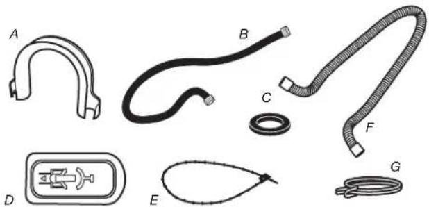
A. U-shaped hose form
B. Water inlet hoses (2)
C. Inlet hose washers (4)
D. Transit bolt hole plug (4)
E. Beaded tie strap
F. Drain hose
Parts supplied for PD Models:
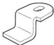
Service door lock cam
Parts supplied for PR Models:
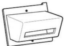
Card reader bezel
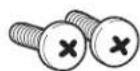
Screws (2)
Alternate Parts
Your installation may require additional parts. If you are interested in purchasing one of the items listed here, call the toll-free number in the "Assistance or Service" section.
| If you have You will need to buy | |
| Laundry tub or standpipe taller than 96" (2.4 m) | Sump pump system (if not already available) |
| Overhead sewer Standard | 20 gal. (76 L), 30" (762 mm) tall drain tub or utility sink and sump pump (available from local plumbing suppliers) |
| Floor drain Siphon break, Part Number 285834; additional drain hose, Part Number 8318155; and connector kit, Part Number 285835 | |
| Drain hose too short 4 ft. (1.2 m) drain hose extension kit, Part Number 285863 | |
| Water faucets beyond reach of fill hoses | 2 longer water fill hoses: 6 ft. (1.8 m) Part Number 76314 10 ft. (3.0 m) Part Number 350008 |
Accessories
Enhance your washer with these premium accessories.
For more high-quality items or to order, call 1-800-344-1274, or visit us at www.maytag.com/accessories. In Canada call:
1-800-688-2002 or visit us at www.maytag.ca/accessories.
| Part Number Accessory | |
| 8212526 | Washer drip trays, fits under all |
| 31682 | All purpose appliance cleaner |
| 1903WH | Laundry supply storage cart |
Options
Pedestal
You have the option of purchasing pedestals separately for this washer. The pedestal will add to the total height of the washer.
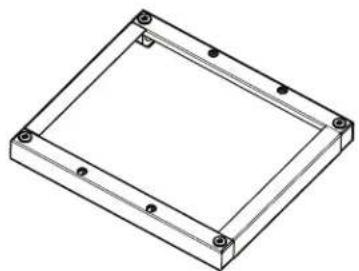
Optional pedestal
| Pedestal Height | Approximate height with washer | Color | Part Number |
| 27½" (73 mm) | 47.5" (1207 mm) | White WHP0400VW |
NOTE: Some models have pedestal pre-installed.
Location Requirements
Selecting the proper location for your washer improves performance and minimizes noise and possible washer "walk."
Your washer can be installed under a custom counter, or in a basement, laundry room, or recessed area. See "Drain System."
Companion appliance location requirements should also be considered. Proper installation is your responsibility.
You will need
A water heater set to deliver 120^ (49^) water to the washer.
A grounded electrical outlet located within 6 ft. (1.8 m) of where the power cord is attached to the back of the washer. See "Electrical Requirements."
Hot and cold water taps located within 4 ft. (1.2 m) of the hot and cold water fill valves, and water pressure of 20 psi-100 psi (137.9 kPa-689.6 kPa).
A level floor with a maximum slope of 1^ (25 mm) under entire washer. Installing the washer on soft floor surfaces, such as carpets or surfaces with foam backing, is not recommended.
A sturdy and solid floor to support the washer with a total weight (water and load) of 400 lbs (180kg)
Do not operate your washer in temperatures below 32^ (0^) . Some water can remain in the washer and can cause damage in low temperatures.
Installation clearances
The location must be large enough to allow the washer door to be fully opened.
Additional spacing should be considered for ease of installation and servicing. The door opens more than 90^ , and it is not reversible.
Additional clearances might be required for wall, door, and floor moldings.
Additional spacing of 1" (25 mm) on all sides of the washer is recommended to reduce noise transfer.
- Companion appliance spacing should also be considered.
Washer Dimensions
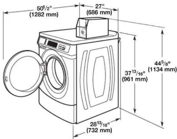
Door is not reversible.
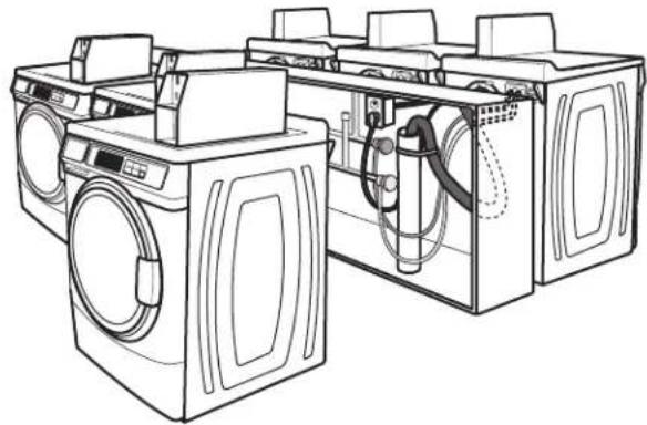
A floor drain should be provided under the bulkhead. Prefabricated bulkheads with electrical outlets, water inlet lines, and drain facilities should be used only where local codes permit.
Drain System
The washer can be installed using the standpipe drain system (floor or wall), the laundry tub drain system, or the floor drain system. Select the drain hose installation method you need. See "Tools and Parts."
Standpipe drain system - wall or floor (views A & B)
The standpipe drain requires a minimum diameter standpipe of 2^ (50 mm). The minimum carry-away capacity can be no less than 10 gal. (38 L) per minute, per washer.
The top of the standpipe must be at least 30^ (762 mm) high and no higher than 96^ (2.4 m) from the bottom of the washer.
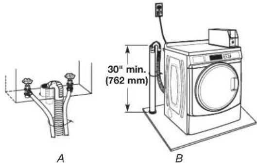
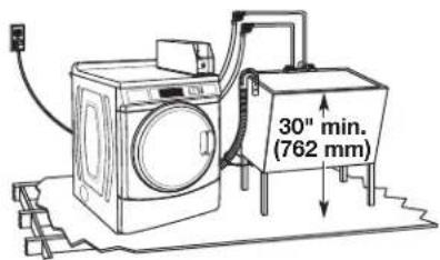
Laundry tub drain system
The laundry tub needs a minimum 20 gal. (76 L) capacity. The top of the laundry tub must be at least 30'' (762 mm) above the floor.
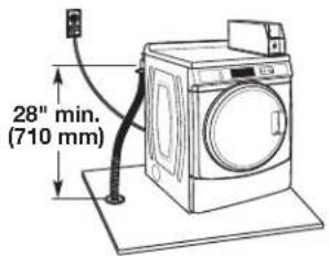
Floor drain system
The floor drain system requires a siphon break that may be purchased separately. See "Tools and Parts."
The siphon break must be a minimum of 28'' (710 mm) from the bottom of the washer. Additional hoses might be needed.
Electrical Requirements
AWARNING

Electrical Shock Hazard
Plug into a grounded 3 prong outlet.
Do not remove ground prong.
Do not use an adapter.
Do not use an extension cord.
Failure to follow these instructions can result in death, fire, or electrical shock.
A 120V,60Hz AC only, 15 A or 20 A, fused electrical supply is required. A time-delay fuse or circuit breaker is recommended. It is recommended that a separate circuit serving only this washer be provided.
This washer is equipped with a power supply cord having a 3 prong grounding plug.
To minimize possible shock hazard, the cord must be plugged into a mating, 3 prong, grounding-type outlet, grounded in accordance with local codes and ordinances. If a mating outlet is not available, it is the personal responsibility and obligation of the customer to have the properly grounded outlet installed by a qualified electrician.
If codes permit and a separate ground wire is used, it is recommended that a qualified electrician determine that the ground path is adequate.
Do not ground to a gas pipe.
Check with a qualified electrician if you are not sure if the washer is properly grounded.
Do not have a fuse in the neutral or ground circuit.
GROUNDING INSTRUCTIONS
For a grounded, cord-connected washer:
This washer must be grounded. In the event of a malfunction or breakdown, grounding will reduce the risk of electrical shock by providing a path of least resistance for electric current. This washer is equipped with a cord having an equipment-grounding conductor and a grounding plug. The plug must be plugged into an appropriate outlet that is properly installed and grounded in accordance with all local codes and ordinances.
WARNING: Improper connection of the equipment-grounding conductor can result in a risk of electric shock. Check with a qualified electrician or serviceman if you are in doubt as to whether the appliance is properly grounded.
Do not modify the plug provided with the appliance - if it will not fit the outlet, have a proper outlet installed by a qualified electrician.
For a permanently connected washer:
This washer must be connected to a grounded metal, permanent wiring system, or an equipment grounding conductor must be run with the circuit conductors and connected to the equipment-grounding terminal or lead on the appliance.
INSTALLATION INSTRUCTIONS
Remove Transport System
WARNING
Excessive Weight Hazard
Use two or more people to move and install washer.
Failure to do so can result in back or other injury.
IMPORTANT: Position the washer so that the rear of the washer is within approximately 3 ft. (900 mm) of its final location.
There are four shipping bolts in the rear panel of the washer that support the suspension system during transportation. These bolts also retain the power cord inside the washer until the bolts are removed.
- Keep the washer in the upright position while removing the shipping bolts.
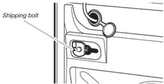
Shipping bolt with plastic spacer
- Using a 1/2 (13 mm) wrench, loosen each of the bolts.
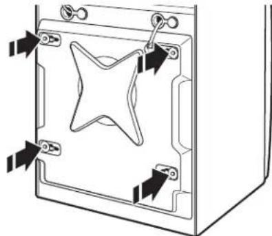
- Once the bolt is loose, move it to the center of the hole and completely pull out the bolt, including the plastic spacer covering the bolt.
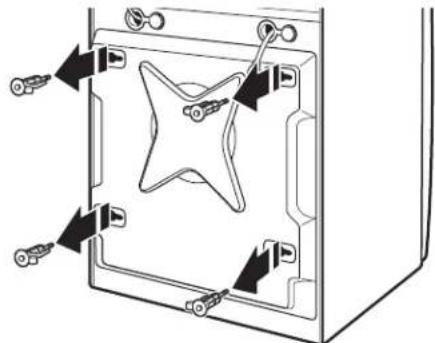
- Once all four bolts are removed, discard the bolts and spacers. Then push the power cord plug into the opening on the right side of the rear panel and pull the power cord through the opening on the left side of the rear panel and close holes with the attached cap. Do not pull plug end of power cord through the right side hole.
- Close the bolt holes with the four transport bolt hole plugs.
NOTE: If the washer is to be transported at a later date, call your product distributor or installer. To avoid suspension and structural damage, your washer must be properly set up for relocation by a trained professional.
Connect the Inlet Hoses
Insert new flat washers (supplied) into each end of the inlet hoses. Firmly seat the washers in the couplings.
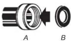
A. Coupling B.Washer
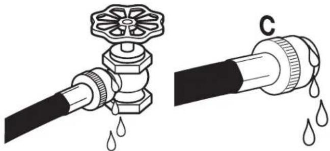
Connect the inlet hoses to water faucets
Make sure the washer drum is empty.
- Attach a hose to the hot water faucet. Screw on coupling by hand until it is seated on the washer.
-
Attach a hose to the cold water faucet. Screw on coupling by hand until it is seated on the washer.
-
Using pliers, tighten the couplings with an additional two-thirds turn.
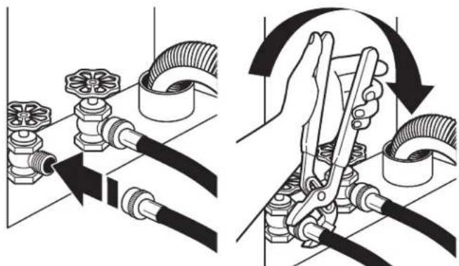
NOTE: Do not overtighten or use tape or sealants on the valve. Damage to the valves can result.
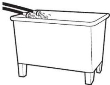
Clear water lines
Run water through both faucets and inlet hoses, into a laundry tub, drainpipe, or bucket, to get rid of particles in the water lines that might clog the inlet valve screens.
- Check the temperature of the water to make sure that the hot water hose is connected to the hot water faucet and that the cold water hose is connected to the cold water faucet.
Connect the inlet hoses to the washer
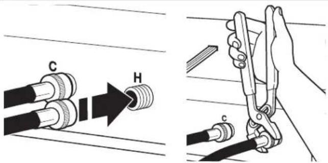
C. Cold water inlet
H. Hot water inlet
- Attach the hot water hose to the check valve on washer's hot (H) water inlet valve. Screw on coupling by hand until it is seated on the check valve.
- Attach the cold water hose to the check valve on washer's cold (C) water inlet valve. Screw on coupling by hand until it is seated on the check valve.
-
Using pliers, tighten the couplings with an additional two-thirds turn. NOTE: Do not overtighten. Damage to the coupling can result.
-
Turn on the water faucets completely and check for leaks and at washer connection.
NOTE: Replace inlet hoses after 5 years of use to reduce the risk of hose failure. Record hose installation or replacement dates on the hoses for future reference.
Periodically inspect and replace hoses if bulges, kinks, cuts, wear, or leaks are found.
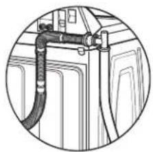
Connect the Drain Hose
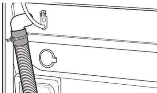
Remove drain hose from washer drum
- Using locking pliers, squeeze hose clamp tabs together and insert over the end of drain hose.
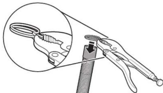
- Slide drain hose onto washer connection.
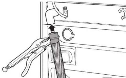
- Once drain hose is in place, release pliers.
Washer drain system can be installed using a floor drain, wall standpipe, floor standpipe, or laundry tub.
Laundry tub drain or standpipe drain
Connect the drain hose form to the corrugated drain hose.
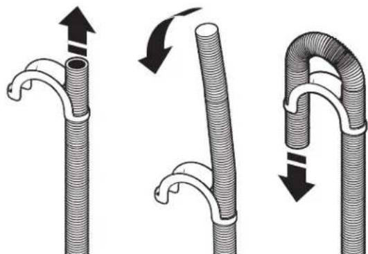
To keep drain water from going back into the washer:
Use the drain hose form, and do not force excess drain hose into standpipe. Hose should be secure but loose enough to provide a gap for air.
Do not lay excess hose on the bottom of the laundry tub.
Floor drain
You may need additional parts. See Floor drain under "Tools and Parts."
Secure the Drain Hose
Drain hose must be secured to stop the hose from moving when water is pumped out. If the drain hose moves, water may end up on the floor.
It is the responsibility of the installer to install and secure the drain hose into the provided plumbing/drain in a manner that will avoid the drain hose coming out of or leaking from the plumbing/drain.
- Drape the power cord over the washer top.
- Move the washer to its final location.
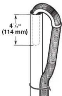
- Place the drain hose in the laundry tub or standpipe as shown. See illustrations A, B, and C.
AB
C
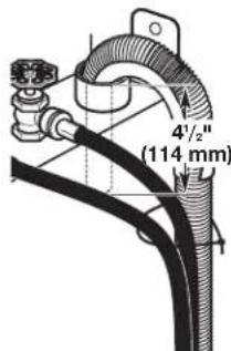
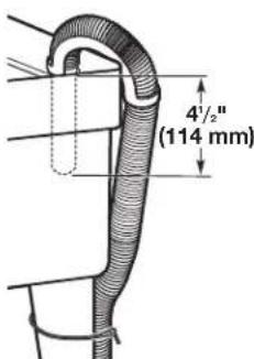
NOTES:
- Do not force excess drain hose back into the rear of the washer.
To avoid siphoning, do not seal or put more than 41/2 (114 mm) of the drain hose into drainpipe or standpipe.
Level the Washer
Properly leveling your washer avoids excessive noise and vibration.
- Check the levelness of the washer by placing a level on the top edge of the washer, first side-to-side, then front to back.
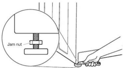
If the washer is against a wall, move the washer out slightly before tipping back. If the washer is not level, first prop the front with a wood block and adjust the feet as necessary; then, prop the back and adjust feet as necessary. Repeat this step until washer is level.
- Make sure all four feet are stable and resting on the floor. Then check that the washer is perfectly level (use a level).
- After the washer is level, use a 9/16" open-end wrench to turn the nuts on the feet tightly against the washer cabinet.
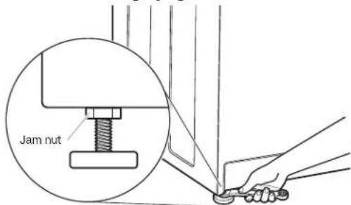
IMPORTANT: All four feet must be tightened. If the nuts are not tight against the washer cabinet, the washer may vibrate.
- The washer should not move front to back, side to side, or diagonally when pushed on its top edges.
- Slide the washer to its final location.
- Confirm the levelness of the washer.
Complete Installation
- Check the electrical requirements. Be sure that you have the correct electrical supply and the recommended grounding method. See "Electrical Requirements."
- Check that all parts are now installed. If there is an extra part, go back through the steps to see which step was skipped.
- Check that you have all of your tools.
- Dispos of/recycle all packaging materials.
- Check that the water faucets are on.
- Check for leaks around faucets and inlet hoses.
AWARNING

Electrical Shock Hazard
Plug into a grounded 3 prong outlet.
Do not remove ground prong.
Do not use an adapter.
Do not use an extension cord.
Failure to follow these instructions can result in death, fire, or electrical shock.
- Plug into a grounded 3 prong outlet.
- To test and to clean your washer, measure 1/2 the detergent manufacturer's recommended amount of High Efficiency (HE) detergent for a medium-size load. Pour the detergent into the detergent dispenser. Select any cycle and allow the washer to complete one whole cycle.
USER & SET-UP INSTRUCTIONS


NOTE: After the washer has been installed and plugged in, the display may show '0 MINUTES'. Once the washer has been plugged in and the washer door opened and closed, the display will show the price. In washers set for free cycles, the display will flash 'SELECT CYCLE'.
- PD Models: Insert coins until 'SELECT CYCLE' flashes in display.
PR Models: A debit card is required rather than coins. In Enhanced Debit mode, the card balance will also display when a debit card is inserted into the reader. - Door must be closed before cycle selection is made,
- Press fabric setting key pad for the wash cycle desired. After the cycle is started, the time will display and count down.
- If a cycle is interrupted by opening the door, 'RESELECT CYCLE' will flash in the display. To restart the washer, close door, and reselect desired cycle.
General User Information
SCROLLING 'OUT OF ORDER' SHOWING IN DISPLAY
This condition indicates the washer is inoperative.
'0 MINUTES'SHOWING IN DISPLAY
This indicates the cycle is complete and the washer cannot be operated. Coins dropped or debit inputs during this condition will be stored in escrow but cannot be used until normal operation is restored by opening and closing the door. If a door switch fails, it must be replaced before normal operation can be restored.
COLD START (Initial first use)
Washer is programmed at the factory as follows:
11-minute wash period
3 rinses (extra rinse not enabled)
$1.75 wash price (PD models)
$0 00 wash price (PR models)
WARM START (after power failure)
A few seconds after power is restored, if a cycle was in progress at the time of the power failure, 'RESELECT CYCLE' will flash in the display, indicating the need for a key press to restart the washer.
DOOR LOCK
Prior to beginning a cycle, there is a door lock routine of lock/unlock/relock; then cycle begins. The door will remain locked until the end of a cycle or approximately 2 minutes after a power interruption.
PRICING
After the door is opened following the completion of a cycle, the display indicates the cycle price (unless set for free operation). As coins are dropped or debit inputs arrive, the display will change to lead the user through the initiation of a cycle.
FREE CYCLES
This is established by setting the cycle price to zero. When this happens, 'SELECT CYCLE' will appear rather than a cycle price.
DEBIT CARD READY
This washer is debit card 'cable' ready. It will accept a variety of debit card systems, but does NOT come with a debit card reader. Refer to the debit card reader manufacturer for proper washer set-up. In models converted to a Generation 1 debit card system, debit pulses represent the equivalent of one coin (coin 1).
Control Set-up Procedures
IMPORTANT: Read all instructions before operating.
PD Models: Insert access door key, turn, and lift to remove access door.
PR Models: Once the debit card reader is installed (according to the reader manufacturer's instructions), the set-up mode can only be entered by inserting a set-up card (supplied by the reader manufacturer) into the card slot. If a set-up card is not available, diagnostic modes can be entered by removing connector AA1 on the circuit board or by using the Service Access Code (see Service Access Code section, page 14) for PR models set up as a PN.
The lower fabric setting key pads and the digital display are used to set up the controls.
The display can contain four numbers and/or letters and a decimal point. These are used to indicate the set-up codes and related code values available for use in programming the washer.
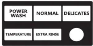
HOW TO USE THE KEY PADS TO PROGRAM THE CONTROLS
- POWERWASH - UPPER LEFT key pad is used to adjust the values associated with set-up codes. Pressing the key pad will increment the value. Rapid adjustment is possible by holding the key pad down.
- The TEMPERATURE - LOWER LEFT key pad is used to adjust the values associated with set-up codes. Pressing the key pad will decrement the value. Rapid adjustment is possible by holding down the key pad.
- The EXTRA RINSE - LOWER MIDDLE key pad will advance through the set-up codes. Pressing the key pad will advance to the next available set-up code. Holding the key pad down will automatically advance through the set-up codes at a rate of 1 per second.
- The DELICATES - UPPER RIGHT key pad is used to select or deselect options.
Start Operating Set-up
Before proceeding, it is worth noting that, despite all of the options available, an owner can simply choose to uncrate a new commercial washer, hook it up, plug it in, and have a washer that operates.
Washers are preset at the factory for an 11-minute wash period and three rinses (no extra rinse).
SET-UP CODES
The EXTRA RINSE - LOWER MIDDLE key pad will advance you from code to code.
The TEMPERATURE - LOWER LEFT and POWERWASH - UPPER LEFT key pads will change the code value.
TheDELICATES - UPPER RIGHT key pad will select or deselect options.
FOR PR MODELS: The set-up codes are the same as for the "PD" model except where noted.
The set-up code is indicated by the one or two left-hand characters. The set-up code value is indicated by the two or three right-hand characters.
| CODE EXPLANATION | |
| 6 07 | NORMAL REGULAR CYCLE PRICE (NormAL Factory Default) |
| 6 07 | Represents the number of quarters (coin 1); may adjust from 0-200. (See VALUE OF COIN 1.) Increase from 0-200 by pressing the UPPER LEFT key pad and decrease by pressing LOWER LEFT key pad. Factory default of 7 quarters = $1.75. |
| 6 00 | PR MODELS ONLY: Factory default of 0 quarters. 6 01 setting would represent one coin slide actuation. → Press the LOWER MIDDLE key pad once to advance to next code. |
| 6 07 | DELICATES REGULAR CYCLE PRICE (Delicates Factory Default) |
| 6 07 | Represents the number of quarters (coin 1); may adjust from 0-200. (See VALUE OF COIN 1.) Increase from 0-200 by pressing the UPPER LEFT key pad and decrease by pressing LOWER LEFT key pad. Factory default of 7 quarters = $1.75. |
| 6 00 | PR MODELS ONLY: Factory default of 0 quarters. 601 setting would represent one coin slide actuation. → Press the LOWER MIDDLE key pad once to advance to next code. |
| 6 07 | POWERWASH REGULAR CYCLE PRICE (Washing Factory Default) |
| 6 07 | Represents the number of quarters (coin 1); may adjust from 0-200. (See VALUE OF COIN 1.) Increase from 0-200 by pressing the UPPER LEFT key pad and decrease by pressing LOWER LEFT key pad. Factory default of 7 quarters = $1.75. |
| 6 00 | PR MODELS ONLY: Factory default of 0 quarters. 6.01 setting would represent one coin slide actuation. → Press the LOWER MIDDLE key pad once to advance to next code. |
| 7 11 | WASH LENGTH |
| 7 11 | This is the number of minutes for WASH. Washer comes from the factory preset with 11 minutes. Choose from 9-17 minutes by pressing the LOWER LEFT key pad. |
| → | Press the LOWER MIDDLE key pad once to advance to next code. |
| 8 00 | ADDITIONAL RINSE OPTION/EXIT SERVICE MODE |
| NOTE: This only affects NORMAL and DELICATES cycles. Additional Rinse is always enabled for POWERWASH. | |
| 8 00 | Additional Rinse not selected 'OFF'. Use this field to exit Service Mode when entered via the key dance. Press and hold the LOWER LEFT key pad to exit Service Mode. |
| 8 Ar | Additional Rinse selected 'ON'. Use this field to exit Service Mode when entered via the key dance. Press and hold the LOWER LEFT key pad to exit Service Mode. Press the LOWER MIDDLE key pad once to advance to next code. |
| 9 00 | CYCLE COUNTER OPTION This option is either SELECTED 'ON' or NOT SELECTED 'OFF'. |
| 9 00 | Not Selected 'OFF'. |
| 9 0C | Selected 'ON' and not able to be deselected. Press the LOWER RIGHT key pad 3 consecutive times to select 'ON'. Once selected 'ON' it cannot be deselected. |
| → | Press the LOWER MIDDLE key pad once to advance to next code. |
| CODE EXPLANATION | |
| 1.00 | MONEY COUNTER OPTION This option is either SELECTED 'ON' or NOT SELECTED 'OFF'. |
| 1.00 | Not Selected 'OFF'. |
| 1.0C | Selected 'ON'. |
| Press the UPPER RIGHT key pad 3 consecutive times to select 'ON' and 3 consecutive times to remove (Not Selected 'OFF'). Counter resets by going from 'OFF' to 'ON'. | |
| 1 C0 | Selected 'ON' and not able to be deselected. To select 'ON' and not able to be deselected, first select 'ON', then within 2 seconds, press the LOWER RIGHT key pad twice, LOWER LEFT key pad once, and exit the set-up mode. |
| → | Press the LOWER MIDDLE key pad once to advance to next code. |
| 2.00 | SPECIAL PRICING OPTIONS This option is either SELECTED 'ON' or NOT SELECTED 'OFF'. |
| 2.00 | Not Selected 'OFF', and next available code will be A.00. |
| 2. SP | Selected 'ON'. Press the UPPER RIGHT key pad once for this selection. |
| NOTE: If SPECIAL PRICING OPTION is selected, there is access to codes '3.XX' through '9.XX'.→ | Press the LOWER MIDDLE key pad once to advance to next code. |
| Options to use if SPECIAL PRICING is selected: | |
| 3.07 | NORMAL SPECIAL CYCLE PRICE |
| NORMAL | |
| 3.07 | Represents the number of quarters (coin 1); may adjust from 0–200. (See VALUE OF COIN 1.) Increase from 0–200 by pressing the UPPER LEFT key pad and decrease by pressing LOWER LEFT key pad. Factory default of 7 quarters = 1.75. |
| 3.00 | PR MODELS ONLY: Factory default of 0 quarters.→Press the LOWER MIDDLE key pad once to advance to next code. |
| 3.07 | DELICATES SPECIAL CYCLE PRICE |
| DELICATES | |
| 3.07 | Represents the number of quarters (coin 1); may adjust from 0–200. (See VALUE OF COIN 1.) Increase from 0–200 by pressing the UPPER LEFT key pad and decrease by pressing LOWER LEFT key pad. Factory default of 7 quarters =1.75. |
| 3.00 | PR MODELS ONLY: Factory default of 0 quarters.→Press the UPPER MIDDLE key pad once to advance to next code. |
| 3.07 | POWERWASH SPECIAL CYCLE PRICE |
| POWERWASH | |
| 3.07 | Represents the number of quarters (coin 1); may adjust from 0–200. (See VALUE OF COIN 1.) Increase from 0–200 by pressing the UPPER LEFT key pad and decrease by pressing LOWER LEFT key pad. Factory default of 7 quarters = $1.75. |
| 3.00 | PR MODELS ONLY: Factory default of 0 quarters.→Press theLOWER MIDDLEkey pad once to advance to next code. |
| 5.00 | TIME-OF-DAY CLOCK, MINUTES |
| 5.00 | This is the TIME-OF-DAY CLOCK, minute setting; select 0-59 minutes by pressing the LOWER LEFT key pad. |
| → | Press the LOWER MIDDLE key pad once to advance to next code. |
| 6.00 | TIME-OF-DAY CLOCK, HOURS NOTE: Uses MILITARY TIME or 24 hr. clock. |
| 6.00 | This is the TIME-OF-DAY CLOCK, hour setting; select 0-23 hours by pressing the LOWER LEFT key pad. Press the LOWER MIDDLE key pad once to advance to next code. |
| 7.00 | SPECIAL PRICE START HOUR NOTE: Uses MILITARY TIME or 24 hr. clock. |
| 7.00 | This is the start hour; 0-23 hours. Select START HOUR by pressing the LOWER LEFT or UPPER LEFT key pad. |
| → | Press the LOWER MIDDLE key pad once to advance to next code. |
| 8.00 | SPECIAL PRICE STOP HOUR NOTE: Uses MILITARY TIME or 24 hr. clock. |
| 8.00 | This is the stop hour; 0-23 hours. Select STOP HOUR by pressing the LOWER LEFT or UPPER LEFT key pad. |
| → | Press the LOWER MIDDLE key pad once to advance to next code. |
| 9.10 | SPECIAL PRICE DAY |
| 9.10 | This represents the day of the week and whether special pricing is selected for that day. A number followed by '0' indicates no selection that particular day (9.10). A number followed by an 'S' indicates selected for that day (9.1S). Days of the week (1-7) are selected by pressing the LOWER LEFT key pad. Press the UPPER RIGHT key pad once to select special pricing for each day chosen. When exiting set-up code '9', the display must show current day of week: |
| DISPLAY DAY OF WEEK CODE (selected) | |
| 10 Day 1 = Sunday 1S 20 Day 2 = Monday 2S 30 Day 3 = Tuesday 3S 40 Day 4 = Wednesday 4S 50 Day 5 = Thursday 5S 60 Day 6 = Friday 6S 70 Day 7 = Saturday 7S | |
| → | Press the LOWER MIDDLE key pad once to advance to next code. |
| A. 00 | VAULT VIEWING OPTION This option is either SELECTED 'ON' or NOT SELECTED 'OFF'. |
| A. 00 | Not Selected 'OFF'. |
| A. SC | Selected 'ON'. Press the UPPER RIGHT key pad once for this selection. When selected, the money and/or cycle counts will be viewable (if counter option(s) is selected) when the coin box is removed. |
| → | Press the LOWER MIDDLE key pad once to advance to next code. |
| CODE EXPLANATION | |
| b. 05 | VALUE OF COIN 1 |
| b. 05 | This represents the value of coin 1 in number of 0.05 increments of the larger coin value. 5 x0.05 = $0.25. By pressing the LOWER LEFT key pad, there is the option of 1-199 for the quantity of $0.05 increments. Press the LOWER MIDDLE key pad once to advance to next code. |
| C. 20 | VALUE OF COIN 2 |
| C. 20 | This represents the value of coin 2 in number of 0.05 increments of the larger coin value. 20 x0.05 = $1.00. PR MODELS ONLY: Factory default of $0.25. By pressing the LOWER LEFT key pad, there is the option of 1-199 for the quantity of $0.05 increments. Press the LOWER MIDDLE key pad once to advance to next code. |
| C. 05 | → |
| d. 00 | COIN SLIDE OPTION This option is either SELECTED 'ON' or NOT SELECTED 'OFF'. Replacement of meter case will be needed for coin slide mounting. |
| d. 00 | Not Selected 'OFF'. |
| d. CS | Selected 'ON'. NOTE: This option needs to be set to '00' unless the meter case has been changed to accept a coin slide device. Press the UPPER RIGHTkey pad 3 consecutive times for this selection. When coin slide mode is selected, set 'b'. equal to value of vend price in $0.05 increments. Set set-up code 6 xx (regular cycle price) and set-up code 3.xx (special cycle price) to number of slide operations. If the installer sets-up 'CS' and a coin drop mechanism is installed, the washer will not register coins that are inserted. |
| → | Press the LOWER MIDDLE key pad once to advance to next code. |
| E. 00 | ADD COINS OPTION This option is either SELECTED 'ON' or NOT SELECTED 'OFF'. This option causes the customer display to show the number of coins (coin 1) to enter, rather than the dollars-and-cents amount. |
| E. 00 | Not Selected 'OFF'. |
| E. AC | Selected 'ON'. Press the UPPER RIGHTkey pad 3 consecutive times for this selection. → |
| H. 00 | COOL TEMPERATURE UPGRADE PRICE |
| H. 00 | Increase from 0-200 by pressing the UPPER LEFT key pad and decrease by pressing LOWER LEFT key pad. Factory default for 0 coins = 0.00. |
| → | Press the LOWER MIDDLE key pad once to advance to next code. |
| H. 00 | WARM TEMPERATURE UPGRADE PRICE |
| WARM | Increase from 0-200 by pressing the UPPER LEFT key pad and decrease by pressing LOWER LEFT key pad. Factory default for 0 coins =0.00. |
| → | Press the LOWER MIDDLE key pad once to advance to next code. |
| H. 00 | HOT TEMPERATURE UPGRADE PRICE |
| HOT | |
| H. 00 | Increase from 0-200 by pressing the UPPER LEFT key pad and decrease by pressing LOWER LEFT key pad. Factory default for 0 coins = 0.00. |
| → | Press the LOWER MIDDLE key pad once to advance to next code. |
| H. 01 | EXTRA RINSE UPGRADE PRICE |
| EXTRA RINSE | |
| H. 01 | Increase from 0-200 by pressing the UPPER LEFT key pad and decrease by pressing LOWER LEFT key pad. Factory default for 0 coins =0.00. |
| → | Press the LOWER MIDDLE key pad once to advance to next code. |
| J. Cd | COIN/DEBIT OPTION |
| J. Cd | Both coin and debit selected. Press the UPPER RIGHT key pad 3 consecutive times for this selection. |
| J. C_ | Coins selected, debit disabled. Press the UPPER RIGHT key pad 3 consecutive times for this selection. |
| J. _d | PR models factory default to J. _d. Debit Card selected, coins disabled. Press the UPPER RIGHT key pad 3 consecutive times to change this selection. |
| J. Ed | Enhanced Debit is self-selected when a Generation 2 card reader is installed in the washer. The Ed option cannot be manually selected or deselected. |
| → | Press the LOWER MIDDLE key pad once to advance to next code. |
| L. 00 | PRICE SUPPRESSION OPTIONThis option causes the customer display to show 'ADD' or 'AVAILABLE' rather than the amount of money to add. (Used mainly in debit installations.) |
| L. 00 | Not Selected 'OFF.' |
| L. PS | Selected 'ON.' Press the UPPER RIGHTkey pad once for this selection. |
| → | Press the LOWER MIDDLE key pad once to advance to next code. |
| n. CE | CLEAR ESCROW OPTIONWhen selected, money held in escrow for 30 minutes without further escrow or cycle activity will be cleared. |
| n. 00 | Not Selected 'OFF'. |
| n. CE | Selected 'ON'. Press the UPPER RIGHTkey pad once for this selection. |
| → | Press the LOWER MIDDLE key pad once to advance to next code. |
| r. 800 | TOP SPIN SPEED RPM |
| r. 800 | This can be selected from the following spin speeds: 600 rpm, 750 rpm, 800 rpm, 1000 (displays as 999) rpm. Step between speeds by pressing the UPPER RIGHT key pad. Factory default of 800 rpm. Press the LOWER MIDDLE key pad once to advance to next code. |
| CODE EXPLANATION | |
| U. 00 | PENNY INIncrement OFFSET |
| U. 00 | This represents the penny increment price offset used in Generation 2 (Enhanced Debit) PR models. Choose from 0-4 pennies by pressing the LOWER LEFT key pad. |
| → | Press the LOWER MIDDLE key pad once to advance to next code. |
| A1. 03 | PREWASH LENGTH |
| A1. 03 | This is the number of minutes of PREWASH. Select between 2 and 7 minutes by pressing the UPPER LEFT key pad to increase or the LOWER LEFT key pad to decrease. |
| → | Press the LOWER MIDDLE key pad once to advance to next code. |
| A2. 03 | FINAL SPIN LENGTH |
| A2. 03 | This is the number of minutes of final high speed spin. Choose from 3-8 minutes by pressing the UPPER LEFT key pad to increase or the LOWER LEFT key pad to decrease. |
| → | Press the LOWER MIDDLE key pad once to advance to next code. |
| A3. 02 | NORMAL CYCLE SETTINGS |
| A3. 02 Allows the owner to select the cycle default options of Water Temperature, Prewash, and Extra Rinse. See Table 1 for specific settings. Normal is set to 02 from the factory. The UPPER LEFT and LOWER LEFT key pads change the values. | |
| A4. 00 | DELICATES CYCLE SETTINGS |
| A4. 00 Allows the owner to select the cycle default options of Water Temperature, Prewash, and Extra Rinse. See Table 1 for specific settings. Delicates is set to 00 from the factory. The UPPER LEFT and LOWER LEFT key pads change the values. | |
| A5. OF | POWERWASH CYCLE SETTINGS |
| A5. OF Allows the owner to select the cycle default options of Water Temperature, Prewash, and Extra Rinse. See Table 1 for specific settings. POWERWASH is set to OFF from the factory. The UPPER LEFT and LOWER LEFT key pads change the values. | |
| Table 1 | |||||||
| A3, A4, or A5 | Extra Rinse | Prewash | Wash Temp | A3, A4, or A5 | Extra Rinse | Prewash | Wash Temp |
| 00 Off | Off Cold | 08 On | Off | Cold | |||
| 01 Off | Off Cool | 09 On | Off | Cool | |||
| 02 | Off | Off | Warm | 0A | On | Off | Warm |
| 03 | Off | Off | Hot | 0b | On | Off | Hot |
| 04 | Off | On | Cold | 0c | On | On | Cold |
| 05 Off | On Cool | 0d On | On | cool | |||
| 06 Off | On | Warm | 0E O | On | Warm | ||
| 07 Off | On Hot | 0F | On On | Hot | |||
If cycle counter (90C) is selected, the following is true:
100 Represents the number 10 2 = 200
of cycles in HUNDREDs
200 Represents the number
of cycles in ONES
2 25 = 25
TOTAL CYCLES = 225
This is "VIEW ONLY" and cannot be cleared.
Press the LOWER MIDDLE key pad once to advance to next code.
If money counter (1.0C or 1.C0) is selected, the following is true:
3 00 Number of dollars
301 = $100.00
in HUNDREDS
4 00 Number of dollars in ONES
468 = $68.00
500 Number of CENTS
575 = $ .75
TOTAL = $168.75
END OF SET-UP PROCEDURES
EXIT FROM SET-UP MODE
PD Models:
Reinstall access door.
PR Models:
- Unplug washer or disconnect power.
- Open console, reinsert plug into AA1, close console.
- Plug in washer or reconnect power.
PR MODELS SET UP AS PN WITH PROGRAMMING SWITCH: Turn key clockwise and remove.
PR MODELS SET UP AS PN WITHOUT PROGRAMMING SWITCH:
Set-up mode can be exited by using procedures from Service Access Code (Below).
SERVICE ACCESS CODE
This code can be entered to access service mode without removing the console. It only functions on washers set up for 0 vend price without any Special Pricing set-up, and the Coin/Debit Option must be set to "J_d". If the washer is not in failure mode, the door must be opened to proceed. Service Access Code contains four steps. Perform the following steps:
- Press the upper left key pad.
- Press the lower right key pad.
- Press the upper right key pad.
- Press the lower left key pad.
NOTE: If the Service Access Code procedure is not completed properly, as noted above, there is a 15 second delay before it can be attempted again.
There are three options to exit from the Service Mode:
- From Set-up Code 8, press the lower left (Temperature) key pad for 4 seconds.
- Wait 2 minutes without touching any key pads (without diagnostic modes running).
- Power down the washer, then reapply power.
WASHER CARE
Cleaning Your Washer
Cleaning the Door Seal/Bellow
- Open the washer door and remove any clothing or items from the washer.
- Inspect inner glass door. If debris is present, wipe off debris using damp cloth.
- Inspect the colored seal/bellow between the door opening and the drum for stained areas. Pull back the seal/bellow to inspect all areas under the seal/bellow and to check for foreign objects.
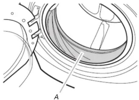
A. Seal/Bellow
- If stained areas are found, wipe down these areas of the seal/bellow, using the procedure that follows:
a) Mix a dilute solution, using 3/4 cup (177 mL) of liquid chlorine bleach, and 1 gal. (3.8 L) of warm tap water.
b) Wipe the seal/bellow area with the dilute solution, using a damp cloth.
c) Let stand 5 minutes.
d) Wipe down area thoroughly with a dry cloth and let the washer interior air dry with door open.
IMPORTANT:
Wear rubber gloves when cleaning for prolonged periods.
Refer to the bleach manufacturer's instructions for proper use.
Washer Maintenance Procedure
This washer has a special cycle that uses higher water volumes in combination with liquid chlorine bleach to thoroughly clean the inside of the washer.
NOTES:
- Read these instructions completely before beginning the cleaning process.
If necessary, the cleaning cycle may be interrupted by pressing the UPPER RIGHT key pad twice. However, this will not immediately stop the cycle. The washer will continue with several rinse and drain steps to ensure that all remaining bleach is rinsed from the washer.
Begin procedure
- Open the washer door and remove any clothing or items from the washer.
2. Use liquid chlorine bleach:
Open the dispenser drawer and immediately add 2/3 cup (160~mL) of liquid chlorine bleach to the bleach compartment.
NOTE: Do not add any detergent to this cycle. Use of more than 2/3 cup (160 mL) of bleach will cause product damage over time.
- Close the washer door and the dispenser drawer.
- To start the Clean Washer cycle, first enter "Start Operating Set-up." Then press and hold the UPPER RIGHT key pad for 1 second. With the entire display flashing, press BRIGHTS.
NOTE: The door will lock, the drum will rotate a 1/2 turn, then the door will unlock, lock again, and then the cycle will continue.
The washer will not fill, but the drum will rotate while the washer runs a short sensing cycle. This will take approximately 3 minutes.
- The cycle will determine whether clothing or other items are in the washer.
a) If no items are detected in the washer, it will proceed to Step 7.
b) If any items are detected in the washer, "rL" or "F-34" will be displayed. Then the door will unlock.
Press theUPPER RIGHTkey pad to cancel the failure code. Then repeat steps 1, 3, and 4 to start the cycle again. - Once the cycle has begun, allow the cycle to complete.
- After the cycle is complete, leave the door open slightly, to allow for better ventilation and drying of washer interior.
Always do the following to maintain washer freshness:
Use only "HE" High Efficiency detergent.
Leave the door slightly open after each cycle to allow for better ventilation and drying of washer interior.
Clean the washer monthly using the Washer Maintenance Procedure and 2/3 cup (160 mL) of liquid chlorine bleach.
If the procedure does not sufficiently improve the washer freshness, please evaluate your installation and usage conditions for other causes.
Cleaning the exterior
Use a soft damp cloth or sponge to wipe up any spills. Occasionally wipe the outside of your washer to keep it looking new. Use mild soap and water. Do not use abrasive products.
Cleaning the dispenser drawer
The dispenser drawer is removable for easy cleaning.
- Unlock the dispenser drawer by pressing the release lever. Remove the drawer.
- Remove the inserts (the siphon from the softener and bleach compartments).
- Wash the parts under running water. NOTE: Do not wash components in the dishwasher.
- Re-install the inserts and return the dispenser to the drawer.
Water Inlet Hoses
Replace water inlet hoses after 5 years of use to reduce the risk of hose failure. Periodically inspect and replace water inlet hoses if bulges, kinks, cuts, wear, or leaks are found.
When replacing your water inlet hoses, mark the date of replacement.
ASSISTANCE OR SERVICE
If you need assistance:
Contact the distributor where the washer was purchased; locate an authorized Maytag Commercial Laundry distributor or visit www.maytagcommerciallaundry.com.
When you call, have the washer model number and serial number. Both numbers can be found on the serial/rating plate located on your washer.
MAYTAG COMMERCIAL LAUNDRY LIMITED WARRANTY
MHN33PD, MHN33PR, MHN33PN, MLE22PD, MLG22PD***,
MLE22PR, MLG22PR, MLE22PN, MLG22PN
IF YOU NEED SERVICE:
Contact your authorized Maytag Commercial Laundry distributor.
To locate your authorized Maytag Commercial Laundry distributor,
visit www.MaytagCommercial Laundry.com.
For written correspondence:
Maytag Commercial Laundry Service Department
2000 N M 63
Benton Harbor, Michigan 49022-2632 USA
SEVEN YEAR LIMITED WARRANTY
WHAT IS COVERED
WHAT IS NOT COVERED
FIVE YEAR LIMITED WARRANTY
(PARTS ONLY - LABOR NOT INCLUDED)
For the first five years from the original date of purchase, when this commercial appliance is installed, maintained, and operated according to the instructions attached to or furnished with the product, Maytag brand of Whirlpool Corporation (hereafter "Maytag") will pay for factory specified replacement parts to correct defects in materials or workmanship that existed when this commercial appliance was purchased. This limited warranty does not include labor.
SIXTH THROUGH SEVENTH YEAR LIMITED WARRANTY
(CERTAIN COMPONENT PARTS ONLY - LABOR NOT INCLUDED)
In the sixth through seventh years from the date of original purchase, when this commercial appliance is installed, operated, and maintained in a vended and/or multi-housing environment ONLY according to instructions attached to or furnished with the product, Maytag will pay for factory specified replacement parts for the following components to correct non-cosmetic defects in materials or workmanship in the part that prevent functioning of the product and that existed when this commercial appliance was purchased. This is a limited 7-year warranty on the below named parts only and does not include labor.
Washer only: Drive Bearings, Tub Seal, Bearing Spacer, Hub, Cross Piece, Drum, Rear Tub, Front Tub, Drum Shaft YOUR SOLE AND EXCLUSIVE REMEDY UNDER THIS LIMITED WARRANTY SHALL BE PART REPLACEMENT AS PROVIDED HEREIN. Maytag recommends that you use an "authorized" service provider to diagnose and repair your Commercial Laundry product. Maytag will not be responsible under this warranty to provide additional replacement parts as a result of incorrect diagnosis or repair by an "unauthorized" service company. Except in the European Union, this limited warranty is valid only when the commercial appliance is used in the country in which it was purchased. This limited warranty is effective from the date of the original consumer purchase. Proof of original purchase date is required to obtain service under this limited warranty.
-
All other costs including labor, transportation, shipping, or custom duties for covered parts.
-
Factory specified replacement parts if this commercial appliance is used for other than normal, commercial use or when it is used in a manner that is inconsistent to published user or operator instructions and/or Installation Instructions.
-
Service calls to correct the installation of your commercial appliance, to instruct you on how to use your commercial appliance, to replace or repair house fuses, or to correct external wiring or plumbing.
-
Service calls to repair or replace appliance light bulbs, air filters, or water filters. Consumable parts are excluded from warranty coverage.
-
Damage resulting from improper handling of product during delivery, theft, accident, alteration, misuse, abuse, fire, flood, acts of God, improper installation, installation not in accordance with local electrical or plumbing codes, or use of products not approved by Maytag.
-
Pick up and delivery. This commercial appliance is designed to be repaired on location.
-
Repairs to parts or systems resulting from unauthorized modifications made to the commercial appliance.
-
The removal and reinstallation of your commercial appliance if it is installed in an inaccessible location or is not installed in accordance with published installation instructions.
-
Damage resulting from exposure to chemicals.
-
Changes to the building, room, or location needed in order to make the commercial appliance operate correctly.
-
Factory specified replacement parts on commercial appliances with original model/serial numbers that have been removed, altered, or cannot be easily determined.
-
Discoloration, rust, or oxidation of stainless steel surfaces.
-
Factory specified replacement parts as a result of incorrect diagnosis or repair by an "unauthorized" service company.
-
Replacement parts during the sixth through seventh years from the date of original purchase where the commercial appliance is installed, operated and maintained in a setting other than a vended and/or multi-housing environment.
-
Replacement parts during the sixth through seventh years from the date of original purchase where the defective part is not preventing the functioning of the product.
The cost of repair or replacement under these excluded circumstances shall be borne by the customer.
DISCLAIMER OF IMPLIED WARRANTYES
IMplied warranties, including any implied warranty of merchantability or implied warranty of fitness for a particular purpose, are limited to seven years or the shortest period allowed by law. Some locations may not allow limitations on the duration of implied warranties of merchantability or fitness, so this limitation may not apply to you. This warranty gives you specific legal rights, and you also may have other rights that vary.
DISCLAIMER OF REPRESENTATIONS OUTSIDE OF WARRANTY
Maytag makes no representations about the quality, durability, or need for service or repair of this major appliance other than the representations contained in this Warranty. If you want a longer or more comprehensive warranty than the limited warranty that comes with this major appliance, you should ask your retailer about buying an extended warranty. The benefits to you given by this warranty are in addition to other rights and remedies available to you under a law in relation to the goods or service to which this warranty relates. Please contact Maytag for further information on warranty terms.
LIMITATION OF REMEDIES; EXCLUSION OF INCIDENTAL AND CONSEQUENTIAL DAMAGES
YOUR SOLE AND EXCLUSIVE REMEDY UNDER THIS LIMITED WARRANTY SHALL BE PRODUCT REPAIR AS PROVIDED HEREIN. MAYTAG SHALL NOT BE LIABLE FOR INCIDENTAL OR CONSEQUENTIAL DAMAGES. Some locations do not allow the exclusion or limitation of incidental or consequential damages, so these limitations and exclusions may not apply to you. This warranty gives you specific legal rights, and you also may have other rights that vary by location.
SECURITE DE LA LAVEUSE
TOTAL PROGRAMMES = 225
ASSISTANCE OU SERVICE
Commercial Laundry agrees le plus proche, consultez
le site Internet www.MaytagCommercial Laundry.com.
Maytag Commercial Laundry Service Department
2000 N M 63
Maytag Commercial Laundry Service Department
2000 N M 63


- INSTALLATION INSTRUCTIONS
- COMMERCIAL FRONT-LOAD WASHER
- INSTRUCTIONS D'INSTALLATION
- LAVEUSE COMMERCIALE À CHARGEMENT FRONTAL
- TABLE DES MATIÈRES
- TABLE DE CONTENIDOS
- Your safety and the safety of others are very important.
- DANGER
- WARNING
- IMPORTANT SAFETY INSTRUCTIONS
- SAVE THESE INSTRUCTIONS
- INSTALLATION REQUIREMENTS
- Tools and Parts
- Tools needed for connecting the water inlet hoses:
- Tools needed for installation:
- Parts supplied:
- Parts supplied for PD Models:
- Parts supplied for PR Models:
- Alternate Parts
- Accessories
- Options
- Pedestal
- Location Requirements
- You will need
- Installation clearances
- Washer Dimensions
- Drain System
- Standpipe drain system - wall or floor (views A & B)
- Laundry tub drain system
- Floor drain system
- Electrical Requirements
- AWARNING
- Electrical Shock Hazard
- GROUNDING INSTRUCTIONS
- For a grounded, cord-connected washer:
- For a permanently connected washer:
- Remove Transport System
- Excessive Weight Hazard
- Connect the Inlet Hoses
- Connect the inlet hoses to water faucets
- Clear water lines
- Connect the inlet hoses to the washer
- Connect the Drain Hose
- Remove drain hose from washer drum
- Laundry tub drain or standpipe drain
- To keep drain water from going back into the washer:
- Floor drain
- Secure the Drain Hose
- NOTES:
- Level the Washer
- Complete Installation
- USER & SET-UP INSTRUCTIONS
- General User Information
- SCROLLING 'OUT OF ORDER' SHOWING IN DISPLAY
- '0 MINUTES'SHOWING IN DISPLAY
- COLD START (Initial first use)
- WARM START (after power failure)
- DOOR LOCK
- PRICING
- FREE CYCLES
- DEBIT CARD READY
- Control Set-up Procedures
- HOW TO USE THE KEY PADS TO PROGRAM THE CONTROLS
- Start Operating Set-up
- SET-UP CODES
- If cycle counter (90C) is selected, the following is true:
- If money counter (1.0C or 1.C0) is selected, the following is true:
- END OF SET-UP PROCEDURES
- EXIT FROM SET-UP MODE
- PD Models:
- PR Models:
- SERVICE ACCESS CODE
- There are three options to exit from the Service Mode:
- WASHER CARE
- Cleaning Your Washer
- Cleaning the Door Seal/Bellow
- IMPORTANT:
- Washer Maintenance Procedure
- Begin procedure
- Use liquid chlorine bleach:
- Always do the following to maintain washer freshness:
- Cleaning the exterior
- Cleaning the dispenser drawer
- Water Inlet Hoses
- ASSISTANCE OR SERVICE
- If you need assistance:
- MAYTAG COMMERCIAL LAUNDRY LIMITED WARRANTY
- SEVEN YEAR LIMITED WARRANTY
- WHAT IS COVERED
- WHAT IS NOT COVERED
- FIVE YEAR LIMITED WARRANTY
- (PARTS ONLY - LABOR NOT INCLUDED)
- SIXTH THROUGH SEVENTH YEAR LIMITED WARRANTY
- (CERTAIN COMPONENT PARTS ONLY - LABOR NOT INCLUDED)
- DISCLAIMER OF IMPLIED WARRANTYES
- DISCLAIMER OF REPRESENTATIONS OUTSIDE OF WARRANTY
- LIMITATION OF REMEDIES; EXCLUSION OF INCIDENTAL AND CONSEQUENTIAL DAMAGES
- SECURITE DE LA LAVEUSE
- ASSISTANCE OU SERVICE
Brand : MAYTAG
Model : MHN33PD
Category : Washing machine