
XMGS6DSP - Car speaker SONY - Free user manual and instructions
Find the device manual for free XMGS6DSP SONY in PDF.
User questions about XMGS6DSP SONY
0 question about this device. Answer the ones you know or ask your own.
Ask a new question about this device
Download the instructions for your Car speaker in PDF format for free! Find your manual XMGS6DSP - SONY and take your electronic device back in hand. On this page are published all the documents necessary for the use of your device. XMGS6DSP by SONY.
USER MANUAL XMGS6DSP SONY
6/5 Channel Class-D Amplifier with DSP
Operating Instructions
GB
Mode d'emploi
FR
The model and serial numbers are located on the bottom of the unit. Record the serial number in the space provided below. Refer to these numbers whenever you call upon your Sony dealer regarding this product.
Model No. XM-GS6DSP
Serial No. ____
To use the unit safely, see "Installation and Connections" (page 6) for details.
The nameplate indicating operating voltage, etc., is located on the bottom of the chassis.
Warning
FOR THE CUSTOMERS IN THE USA. NOT APPLICABLE IN CANADA, INCLUDING IN THE PROVINCE OF QUEBEC.
POUR LES CLIENTS AUX ÉTATS-UNIS. NON APPLICABLE AU CANADA, Y COMPRIS LA PROVINCE DE QUÉBEC.
This equipment has been tested and found to comply with the limits for a Class B digital device, pursuant to Part 15 of the FCC Rules.
These limits are designed to provide reasonable protection against harmful interference in a residential installation. This equipment generates, uses, and can radiate radio frequency energy and, if not installed and used in accordance with the instructions, may cause harmful interference to radio communications. However, there is no guarantee that interference will not occur in a particular installation. If this equipment does cause harmful interference to radio or television reception, which can be determined by turning the equipment off and on, the user is encouraged to try to correct the interference by one or more of the following measures:
— Reorient or relocate the receiving antenna.
— Increase the separation between the equipment and receiver.
- Connect the equipment into an outlet on a circuit different from that to which the receiver is connected.
— Consult the dealer or an experienced radio/TV technician for help.
You are cautioned that any changes or modifications not expressly approved in this manual could void your authority to operate this equipment.
This device complies with Part 15 of the FCC Rules and Industry Canada's licence-exempt RSSs. Operation is subject to the following two conditions:
(1) This device may not cause interference; and (2) This device must accept any interference, including interference that may cause undesired operation of the device.
This transmitter must not be co-located or operated in conjunction with any other antenna or transmitter.
Under Industry Canada regulations, this radio transmitter may only operate using an antenna of a type and maximum (or lesser) gain approved for the transmitter by Industry Canada. To reduce potential radio interference to other users, the antenna type and its gain should be so chosen that the equivalent isotropically radiated power (e.i.r.p.) is not more than that necessary for successful communication.
This equipment complies with FCC/IC radiation exposure limits set forth for an uncontrolled environment and meets the FCC radio frequency (RF) Exposure Guidelines and RSS-102 of the IC radio frequency (RF) Exposure rules. This equipment has very low levels of RF energy that is deemed to comply without maximum permissive exposure evaluation (MPE).
Important notice
Caution
IN NO EVENT SHALL SONY BE LIABLE FOR ANY INCIDENTAL, INDIRECT OR CONSEQUENTIAL DAMAGES OR OTHER DAMAGES INCLUDING, WITHOUT LIMITATION, LOSS OF PROFITS, LOSS OF REVENUE, LOSS OF DATA, LOSS OF USE OF THE PRODUCT OR ANY ASSOCIATED EQUIPMENT, DOWNTIME, AND PURCHASER'S TIME RELATED TO OR ARISING OUT OF THE USE OF THIS PRODUCT, ITS HARDWARE AND/OR ITS SOFTWARE.
Dear customer, this product includes a radio transmitter.
Please check your vehicle operation manual or contact the manufacturer of your vehicle or your vehicle dealer, before you install this product into your vehicle.
Emergency calls
This BLUETOOTH car handsfree and the electronic device connected to the handsfree operate using radio signals, cellular, and landline networks as well as user-programmed function, which cannot guarantee connection under all conditions. Therefore do not rely solely upon any electronic device for essential communications (such as medical emergencies).
On BLUETOOTH communication
- Microwaves emitting from a BLUETOOTH device may affect the operation of electronic medical devices. Turn off this unit and other BLUETOOTH devices in the following locations, as it may cause an accident.
- where inflammable gas is present, in a hospital, train, airplane, or petrol station
- near automatic doors or a fire alarm
- hIs unit supports security capabilities that comply with the BLUETOOTH standard to provide a secure connection when the BLUETOOTH wireless technology is used, but security may not be enough depending on the setting. Be careful when communicating using BLUETOOTH wireless technology.
- W do not take any responsibility for the leakage of information during BLUETOOTH communication.
If you have any questions or problems concerning your unit that are not covered in this manual, consult your nearest Sony dealer.
Features
- Sony 5-speaker system with 4.1ch DSP connection supported.
- δny 3-way component speaker connection supported.
- Bletooth® connection with your iPhone/Android™ smartphone supported.
- Maximum power output of 100 W per channel (FRONT/REAR at 4 Ω) and 300 W per channel (SUB at 2 Ω).
- is unit can be used as a bridging amplifier with a maximum output of 1,100 W (SUB at 2 Ω).
- Bilt-in LPF (low-pass filter) (REAR/SUB), HPF (high-pass filter) (FRONT/REAR), and Low boost circuit (SUB).
- Protection circuit and indicator provided.
- Dect connection can be made with the speaker output of your car audio unit if that is not equipped with the line output (High level input connection).
- Hlevel Sensing Power On feature allows this unit to be activated without the need for a REMOTE connection.
- Use power supply* for stable and regulated output power.
\* Pulse power supply
This unit has a built-in power regulator which converts the power supplied by the 12 V DC car battery into high speed pulses using a semiconductor switch. These pulses are stepped up by the built-in pulse transformer and separated into both positive and negative power supplies before being converted into direct current again. This is to regulate fluctuating voltage from the car battery. This lightweight power supply system provides a highly efficient power supply with a low impedance output.
Table of Contents
Warning 2
Features. 4
Operation
Location and Function of Controls .... 5
Installation and Connections
Parts for Installation and Connections ..... 6
Installation 7
Connections 7
Power connections....8
REMOTE connections 9
Input connections.... 10
Speaker connections 14
BLUETOOTH
Preparing a BLUETOOTH Device 15
Pairing and connecting with a BLUETOOTH device 15
Connecting with a paired BLUETOOTH device 16
Playing a BLUETOOTH Device 16
Settings
DSP Settings 17
Sony | Music Center with iPhone/Android smartphone 17
Establishing the Sony | Music Center connection 17
Configuring the DSP settings 17
Additional Information
Precautions 18
About iPod 19
Maintenance 19
Fuse replacement 19
Specifications 20
Copyrights 21
Troubleshooting 21
Support Site 23
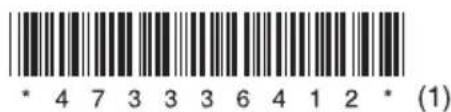
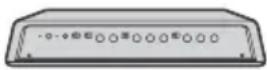
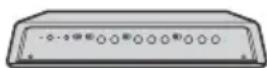
Location and Function of Controls
Control panel side
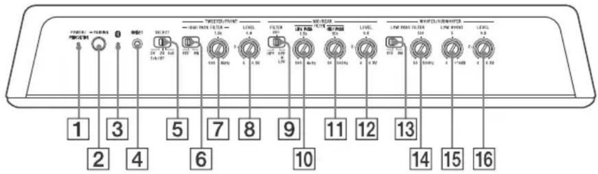
Connector panel side
1 POWER/PROTECTOR indicator (green)
- Lights up when the unit is turned on.
- Flashes when the unit detects an abnormality. See "Troubleshooting" (page 21) for solutions to problems.
2 PAIRING button
Press and hold for 2 seconds to enter the pairing standby mode.
Press and hold for 7 seconds to turn off the BLUETOOTH functions (BLUETOOTH off mode). (Available only when the SELECT switch is set to the "2V" or "5V" position.)
3 (BLUETOOTH) indicator (blue)
- Flashes quickly in pairing standby mode.
- Flashes slowly in BLUETOOTH standby mode.
- Lights up when BLUETOOTH connection is established.
4 BSET button
Resets the unit to the factory defaults (the DSP settings and BLUETOOTH pairing information stored on the unit are also erased).
Press with a pointed object such as a ballpoint pen.
5 SEECT (input select) switch
Selects "2ch/BT" or "6ch" mode depending on the use/non-use of the DSP. When selecting the "2ch/BT" mode, also select the sensitivity "2V" or "5V" depending on the pre-output level of your car audio unit (page 10).
TWEETER/FRONT (tweeter/front speaker) section:
6 HGH PASS FILTER switch
Turns the high-pass filter on/off.
7 HGH PASS FILTER control
Adjusts the cut-off frequency (500 Hz - 4 kHz).
8 LEVEL control
Adjusts the input level (0.3 V - 6 V). Turn it dockwise when the output level of the audio device seems low.
MID/REAR (midrange/rear speaker) section:
9 RTER switch
Selects "HPF" (high-pass filter) or "HPF+LPF" (high-pass and low-pass filters) according to the speaker system.
10 LOW PASS FILTER control
Adjusts the cut-off frequency (500 Hz - 4 kHz).
11 HGH PASS FILTER control
Adjusts the cut-off frequency (50 Hz - 500 Hz).
12 LEVEL control
Adjusts the input level (0.3 V – 6 V). Turn it clockwise when the output level of the audio device seems low.
WOOFER/SUBWOOFER (woofer/subwoofer) section:
13 LOW PASS FILTER switch
Turns the low-pass filter on/off.
14 LOW PASS FILTER control
Adjusts the cut-off frequency (50 Hz - 500 Hz).
15 LOW BOOST control
Boosts the frequencies around 40 Hz to a maximum of 10 dB (0 dB - 10 dB).
16 LEVEL control
Adjusts the input level (0.3 V - 6 V). Turn it clockwise when the output level of the audio device seems low.
17 LINE INPUT connector
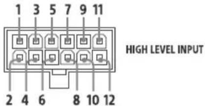
18 HIGH LEVEL INPUT connector
19 REMOTE IN jack
For a wired remote control (not supplied)
SPEAKER OUT section:
20 TWETER/FRONT/MID/REAR connector
21 WOFER/SUBWOOFER terminals
POWER section:
22 Fse (30 A)
23 A C (accessary) terminal
+12V terminal
GND (ground (earth)) terminal
Installation and Connections
Parts for Installation and Connections
①
5 × 20 mm (7/32 × 13/16 in)

②
③
④
⑤
This parts list does not include all the package contents.
Installation
- Select the mounting location where it is easy to press the PAIRING button on the unit.
- Koose the mounting location carefully so the unit will not interfere with the normal movements of the driver and it will not be exposed to direct sunlight or hot air from the heater.
- Do not mount the unit in a confined space such as under the floor carpet that will obstruct heat dissipation.
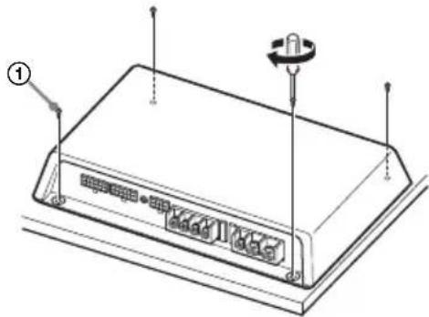
Mounting the unit
First, place the unit where you plan to install it, and mark the positions of the 4 screw holes on a mounting board (not supplied). Then drill a 3 mm (1/8 in) pilot hole at each mark and mount the unit onto the board with the supplied mounting screws. The mounting screws are all 20 mm ( ^13/16 in) long, so make sure that the mounting board is thicker than 20 mm ( ^13/16 in).
natural_image
Diagram of a rectangular electronic device with labeled ports and a knob, no text or symbols presentConnections
- Before making any connections, disconnect the ground (earth) terminal of the car battery to avoid short circuits.
- Beure to use speakers with an adequate power rating. If you use small capacity speakers, they may be damaged.
- D not connect the ⊖ terminal of the speaker system to the car chassis, and do not connect the ⊖ terminal of the right speaker with that of the left speaker.
- nstall the input and output cords away from the power supply wire. Running them close together may generate interference noise.
- His unit is a high powered amplifier. Therefore, it may not perform to its full potential if used with the speaker cords supplied with the car.
- flyour car is equipped with a computer system for navigation or some other purpose, do not remove the ground (earth) wire from the car battery. If you disconnect the wire, the computer memory may be erased. To avoid short circuits when making connections, disconnect the +12 V power supply wire until all the other wires have been connected.
Making the terminal connections
Pass the wires through the cap, connect the wires, then cover the terminals with the cap.
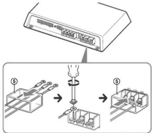
Note
When you tighten a screw, be careful not to apply too much torque as doing so may damage the screw (the torque value should be less than 1 N·m).
Power connections
- Connect the +12 V power supply wire only after all the other wires have been connected.
- Be she to connect the ground (earth) wire of the unit securely to a metal point of the car. A loose connection may cause a malfunction of the amplifier.
- Wen using a car audio unit without a remote output (REMOTE OUT) for the amplifier, connect the remote input (REM) terminal to the accessory power supply.
- Be a power supply wire with a fuse (60 A) attached.
- A power wires connected to the positive battery post should be fused within 450 mm (17 ^3 /4 in) of the battery post, and before they pass through any metal.
- Take sure that the car's battery wires connected to the car (ground (earth) to chassis) are of a wire gauge at least equal to that of the main power wire connected from the battery to the amplifier.
- Dring full-power operation, a current of more than 60 A will run through the system. Therefore, make sure that the wires to be connected to the +12 V and GND terminals of this unit are at least 8-Gauge (AWG-8) or have a sectional area of more than 8 mm ^2 (11/32 in ^2 ).
Making power connections
Power connection wires (not supplied) are required.
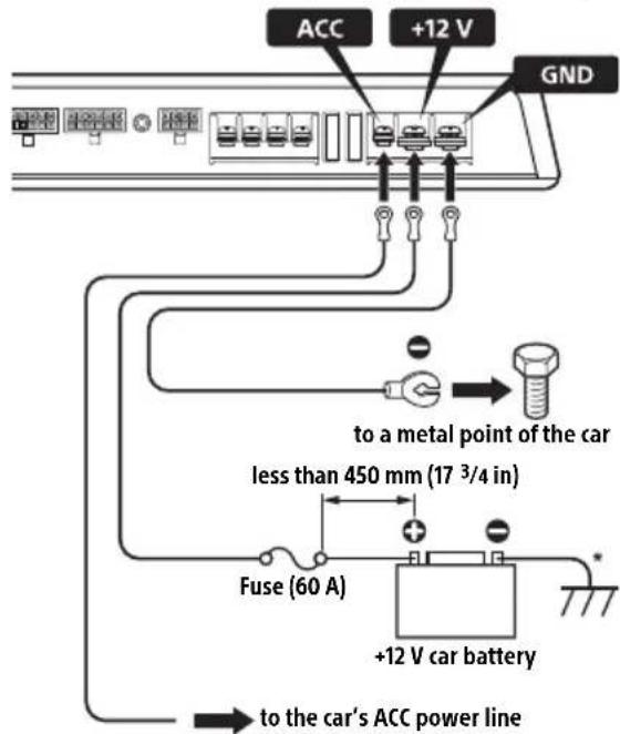
* Ground (earth) to chassis.
REMOTE connections
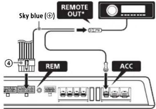
For the line input connections A (page 10), B (page 11) or C (page 11) only. Connect the remote out (REMOTE OUT) from your car audio unit to the appropriate position.
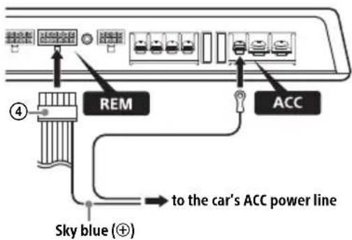
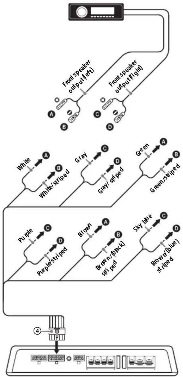
When your car's ignition has an ACC position
Connect the remote out (REMOTE OUT) from your car audio unit to the remote input (REM) terminal via the high level connector ④ (sky blue lead ⊕), and connect the ACC terminal to the car's ACC power line.
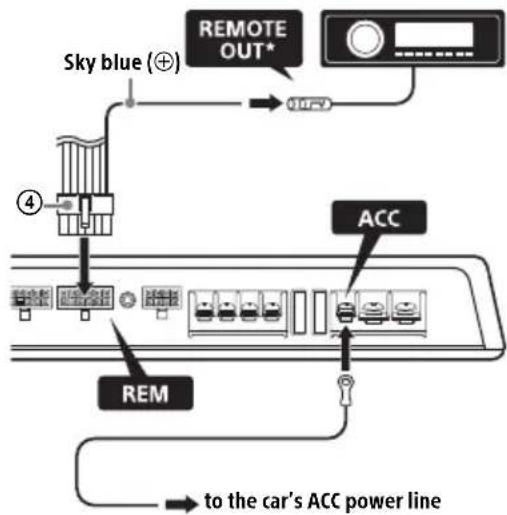
* The REMOTE connection is not necessary when making the high level input connection D (page 12), E (page 12) and F (page 13).
If your car audio unit has no REMOTE OUT
Connect the ACC terminal to the car's ACC power line, and connect the remote input (REM) terminal to the car's ACC power line via the high level input connector ④ (sky blue lead ⊕).
When your car's ignition has no ACC position
Connect the remote out (REMOTE OUT) from your car audio unit to the ACC terminal, and connect the remote out (REMOTE OUT) from your car audio unit to the remote input (REM) terminal via the high level input connector ④ (sky blue lead ⊕).
flowchart
graph TD
    A["Sky blue (⊕)"] --> B["REMOTE OUT*"]
    B --> C["RES"]
    C --> D["ACC"]
    style A fill:#f9f,stroke:#333
    style D fill:#bbf,stroke:#333
* With this connection, a BLUETOOTH device cannot be played while the car audio unit is turned off.
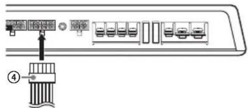
If your car audio unit has no REMOTE OUT Connect the high level input connector ④.\*
* With this connection, a BLUETOOTH device cannot be played while the car audio unit is turned off.
Input connections
Set the SELECT switch to the appropriate position according to the speaker system.
2ch/BT mode and 6ch mode
Select "2ch/BT" or "6ch" mode depending on the use/non-use of the DSP.
When selecting the "2ch/BT" mode, also select the sensitivity "2V" or "5V" depending on the pre-output level of your car audio unit.
| Mode For | |
| 6ch (Through mode) | → using this unit as a 6ch amplifier (no built-in DSP is used)*1. For details on the connections, see:– “BLine input connection (for Subwoofer BTL system/6ch mode)”(page 11).– “EHigh level input connection (for Subwoofer BTL system/6ch mode)”(page 12).→ using this unit with a 3-way speaker system. With this connection, a 3-ways speaker system can be driven without a crossover network. For details on the connections, see:– “CLine input connection (for 3-way speaker system/6ch mode)”(page 11).– “FHigh level input connection (for 3-way speaker system/6ch mode)”(page 13). |
| 2ch/BT (DSP mode)*2*3 | → encoding 2ch input signals into 4.1ch output signals (the built-in DSP is used). For details on the connections, see:– “ALine input connection (with DSP enabled/2ch mode)”(page 10).– “DHigh level input connection (with DSP enabled/2ch mode)”(page 12).→ playing a BLUETOOTH device by operating the “Sony | Music Center” application. For details, see “Playing a BLUETOOTH Device”(page 16). |
| 2V | Setting the sensitivity “2V” or “5V” of the “2ch/BT” mode. Normally, use this unit set to “2V”.When using a car audio unit with a high pre-output level, set to “5V” if the sound is distorted while increasing the volume. |
| 5V | |
*1 While a bridged subwoofer connection is made, this unit functions as a 5ch amplifier.
*2 When adjusting the volume balance of the front speakers, rear speakers and subwoofer while the unit is in 2ch mode (DSP mode), operate your iPhone/Android smartphone to adjust the [Fader], [Balance] and [Subwoofer Level] settings of the "Sony | Music Center" application.
*3 The sound settings of the DSP (page 17) can be made by the "Sony | Music Center" application on the iPhone/Android smartphone. Before setting, operate your iPhone/Android smartphone to establish the BLUETOOTH connection with this unit (page 15).
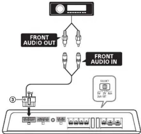
A Line input connection (with DSP enabled/2ch mode)
With the speaker connection 1 (page 14)
flowchart
graph TD
    A["Device"] --> B["FRONT AUDIO OUT"]
    A --> C["FRONT AUDIO IN"]
    C --> D["SELECT 5V 2V 80Hz 2ch/1BT"]
    D --> E["Device ③"]
    style A fill:#f9f,stroke:#333
    style B fill:#ccf,stroke:#333
    style C fill:#ccf,stroke:#333
    style D fill:#cfc,stroke:#333
    style E fill:#fcc,stroke:#333
Notes
- Wen making this connection, set the SELECT switch to the "2V" position.
- The SELECT switch to the "5V" position if the sound is distorted when increasing the volume of the car audio unit (only for car audio unit with a pre-output level of 5 V).
B Line input connection (for Subwoofer BTL system/6ch mode)
With the speaker connection 1 or 2 (page 14)
flowchart
graph TD
    A["Device"] --> B["FRONT AUDIO OUT"]
    A --> C["REAR AUDIO OUT"]
    A --> D["SUB AUDIO OUT"]
    A --> E["FRONT AUDIO IN"]
    A --> F["REAR AUDIO IN"]
    A --> G["SUB AUDIO IN"]
    B --> H["Select 5V 2V 6ch 2ch/8T"]
    C --> I["Select 5V 2V 6ch 2ch/8T"]
    D --> J["Select 5V 2V 6ch 2ch/8T"]
    E --> K["Select 5V 2V 6ch 2ch/8T"]
    F --> L["Select 5V 2V 6ch 2ch/8T"]
    G --> M["Select 5V 2V 6ch 2ch/8T"]
    H --> N["Device"]
    I --> O["Device"]
    J --> P["Device"]
    K --> Q["Device"]
    L --> R["Device"]
    M --> S["Device"]
Notes
- Wen making this connection, set the SELECT switch to the "6ch" position.
- Make sure the signal to SUB AUDIO IN is monaural. SUB AUDIO IN of this unit does not support stereo signal input.
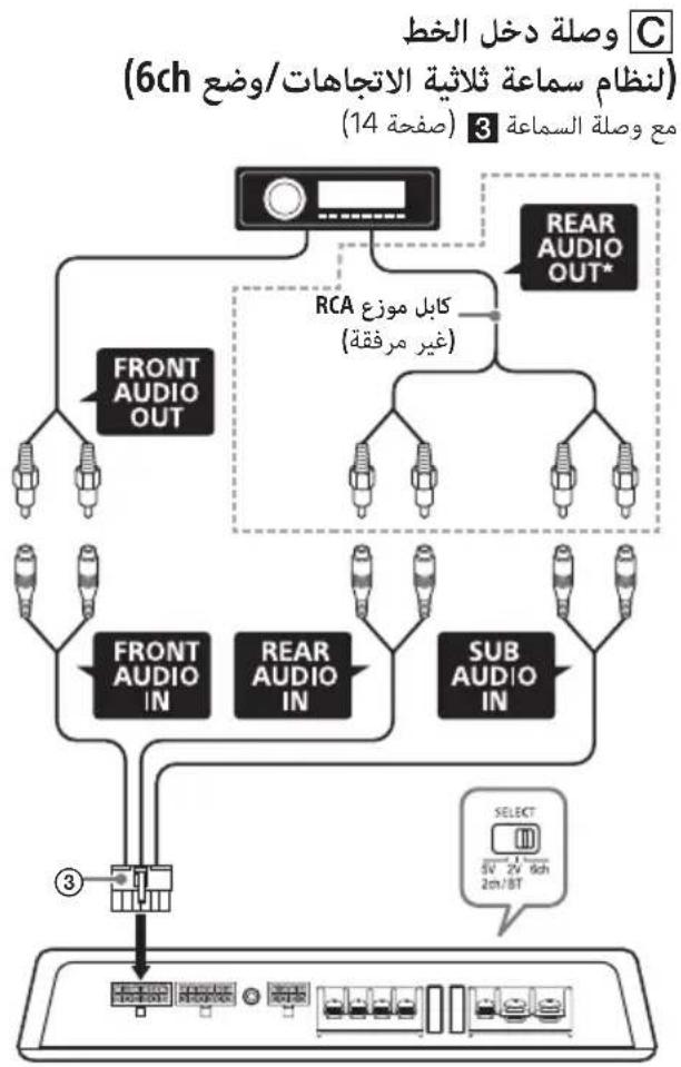
C Line input connection (for 3-way speaker system/6ch mode)
With the speaker connection 3 (page 15)
flowchart
graph TD
    A["REAR AUDIO OUT*"] --> B["FRONT AUDIO OUT"]
    A --> C["RCA splitter cable (not supplied)"]
    C --> D["FRONT AUDIO IN"]
    C --> E["REAR AUDIO IN"]
    C --> F["SUB AUDIO IN"]
    D --> G["3"]
    E --> G
    F --> G
    G --> H["Select 5V 2V Sch/ BT"]
Note
When making this connection, set the SELECT switch to the "6ch" position.
* Use an RCA splitter cable (not supplied) to branch the signals from REAR AUDIO OUT to REAR AUDIO IN and SUB AUDIO IN.
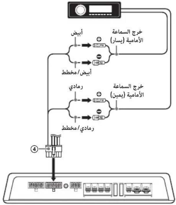
D High level input connection (with DSP enabled/2ch mode)
With the speaker connection 1 (page 14)
flowchart
graph TD
    A["White"] --> B["White/stripped"]
    B --> C["Front speaker output (left)"]
    B --> D["Gray/stripped"]
    D --> E["Front speaker output (right)"]
    C --> F["Output 4"]
    E --> F
E High level input connection (for Subwoofer BTL system/6ch mode)
With the speaker connection 1 or 2 (page 14)
flowchart
graph TD
    A["Input"] --> B["White"]
    B --> C["White/striped"]
    C --> D["Gray"]
    D --> E["Gray/striped"]
    E --> F["Green"]
    F --> G["Green/striped"]
    G --> H["Purple"]
    H --> I["Purple/striped"]
    I --> J["Brown"]
    J --> K["Brown/(black) striped"]
    K --> L["Brown/(blue) striped"]
    L --> M["Output"]
    style A fill:#f9f,stroke:#333
    style M fill:#ccf,stroke:#333
Note
If subwoofer outputs are not equipped to your car audio unit, use this unit as a 4ch amplifier, or make the connection in 2ch mode (☐) instead.
F High level input connection (for 3-way speaker system/6ch mode)
With the speaker connection 3 (page 15)
flowchart
graph TD
    A["Device"] --> B["Front Speaker output (left)"]
    A --> C["Front Speaker output (right)"]
    B --> D["White"]
    B --> E["Gray"]
    C --> F["Green"]
    D --> G["White/striped"]
    E --> H["Gray/striped"]
    F --> I["Green/striped"]
    G --> J["Purple"]
    H --> K["Brown"]
    I --> L["Sky blue"]
    J --> M["Purple/striped"]
    K --> N["Brown/(pack) striped"]
    L --> O["Brown/(blue) striped"]
    M --> P["Output"]
    N --> P
    O --> P
    P --> Q["Device"]
High level input cord connection
Connect the cords properly to speakers.
| 1 | FL Front speaker (left) White/striped | ⊕ | White |
| 2 | |||
| 3 | FR Front speaker (right) Gray/striped | ⊕ | Gray |
| 4 | |||
| 5 | RL Rear speaker (left) Green/striped | ⊕ | Green |
| 6 | |||
| 7 | RR Rear speaker (right) Purple/striped | ⊕ | Purple |
| 8 | |||
| 9 | SL Subwoofer (left) | ⊕ | Brown |
| 10 | Brown/(black) striped | ||
| 11 | SR Subwoofer (right) | ⊕ | Sky blue |
| 12 | Brown/(blue) striped |
Speaker connections
Set the HIGH PASS FILTER switch, FILTER switch and LOW PASS FILTER switch on the control panel to the appropriate positions according to the speaker system.
Also, refer to the manual supplied with your speakers for further details.
1 4.1ch speaker system with a bridged subwoofer connection
With the input connection A or B (page 10, 11)
flowchart
graph TD
    A["Front speaker (min. 4 Ω)"] --> B["R"]
    C["Rear speaker (min. 4 Ω)"] --> D["R"]
    E["High Pass Filter OFF ON"] --> F["Filter OFF HP+ LPF"]
    G["Low Pass Filter QTY ON"] --> H["Filter QTY HP+ LPF"]
    I["Subwoofer (min. 2 Ω)"] --> J["BTL"]
    style A fill:#f9f,stroke:#333
    style C fill:#f9f,stroke:#333
    style E fill:#ccf,stroke:#333
    style G fill:#ccf,stroke:#333
    style I fill:#cfc,stroke:#333
    style J fill:#fcc,stroke:#333
Notes
- Wen making this connection, set the filter switches to the following positions:
-HIGH PASS FILTER: OFF
- FILTER: OFF
- LOW PASS FILTER: ON
- Wen adjusting the volume balance of the front speakers, rear speakers and subwoofer while the unit is in 2ch mode (DSP mode), operate your iPhone/Android smartphone to adjust the [Fader], [Balance] and [Subwoofer Level] settings of the "Sony | Music Center" application.
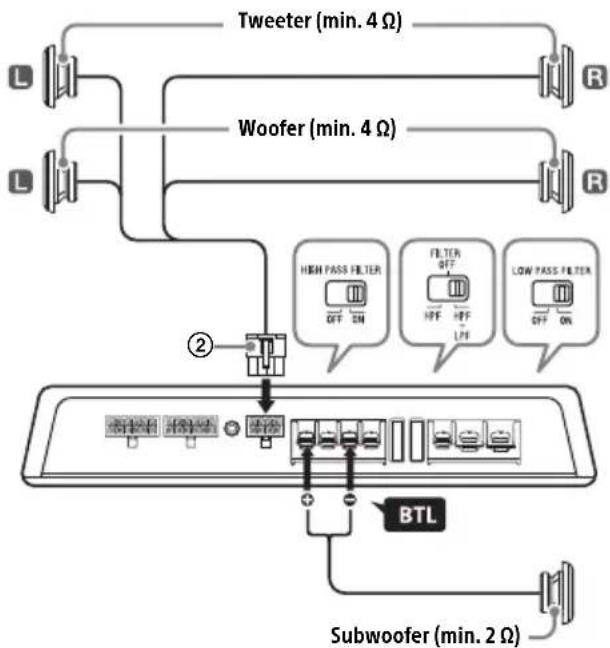
2 2-way speaker system with a bridged subwoofer connection
With the input connection A or B (page 10, 11)
flowchart
graph TD
    A["Tweeter (min. 4 Ω)"] --> B["R"]
    C["Woofer (min. 4 Ω)"] --> D["R"]
    E["High Pass Filter OFF ON"] --> F["FFP"]
    G["Filter OFF HPF"] --> H["LPF"]
    I["Low Pass Filter OFF ON"] --> J["OFF ON"]
    K["BTL"] --> L["Subwoofer (min. 2 Ω)"]
    M["Switch"] --> N["Control Panel"]
    O["Switch"] --> P["Control Panel"]
    Q["Switch"] --> R["Control Panel"]
Note
When making this connection, set the filter switches to the following positions:
-HIGH PASS FILTER: ON
- FILTER: HPF+LPF
- LOW PASS FILTER: ON
3 3-way speaker system
With the input connection C (page 11) Using Sony 3 Way Component Speaker System XS-GS1631C is recommended.
flowchart
graph TD
    A["Tweeter (min. 4 Ω)"] --> B["Midrange speaker (min. 4 Ω)"]
    B --> C["High Pass Filter"]
    B --> D["Filter"]
    B --> E["Low Pass Filter"]
    C --> F["Grid of switches"]
    D --> G["Grid of switches"]
    E --> H["Grid of switches"]
    I["Woofer (min. 2 Ω)"] --> J["Grid of switches"]
    K["L"] --> L["Switch"]
    M["R"] --> N["Switch"]
    O["L"] --> P["Switch"]
    Q["L"] --> R["Switch"]
    S["R"] --> T["Switch"]
Note
When making this connection, set the filter switches to the following positions:
-HIGH PASS FILTER: ON
- FILTER: HPF+LPF
- LOW PASS FILTER: ON
Speaker cord connection
Connect the cords properly to speakers.
| 1 | FL Front speaker (left) White/striped | ⊕ | White |
| 2 | |||
| 3 | FR Front speaker (right) Gray/striped | ⊕ | Gray |
| 4 | |||
| 5 | RL Rear speaker (left) Green/striped | ⊕ | Green |
| 6 | |||
| 7 | RR Rear speaker (right) Purple/striped | ⊕ | Purple |
| 8 |
BLUETOOTH
Preparing a BLUETOOTH Device
You can enjoy music on a BLUETOOTH compatible device such an iPhone/Android smartphone (hereafter "BLUETOOTH device" if not otherwise specified). For details on connecting, refer to the operating instructions supplied with the device. Before connecting the device, turn down the volume of the BLUETOOTH device; otherwise, a loud sound may result. (Available only when the SELECT switch is set to the "2V" or "5V" position.)
Pairing and connecting with a BLUETOOTH device
When connecting a BLUETOOTH device for the first time, mutual registration (called "pairing") is required. Pairing enables this unit and other devices to recognize each other.
flowchart
graph LR
    A["手机"] --> B["X-shaped arrow"]
    B --> C["Device with four circular buttons"]
1 Place the BLUETOOTH device within 1 m (3 ft) of this unit.
2 Press and hold PAIRING for 2 seconds.
The indicator flashes quickly while the unit is in pairing standby mode.
3 Perform pairing on the BLUETOOTH device so it detects this unit.
4 Select [XM-GS6DSP] shown in the display of the BLUETOOTH device.
If your model name does not appear, repeat from step 2.
5 If passkey input is required on the BLUETOOTH device, input [0000]. When pairing is made, the ✕ indicator flashes slowly.
6 Select this unit on the BLUETOOTH device to make the BLUETOOTH connection. The indicator lights up when the connection is established.
Note
While connected to a BLUETOOTH device, this unit cannot be detected from another device. To enable detection, press PAIRING to enter the pairing standby mode and search for this unit from another device.
To start playback
For details, see "Playing a BLUETOOTH Device" (page 16).
To disconnect the paired device
Perform step 2.
Connecting with a paired BLUETOOTH device
To use this unit with BLUETOOTH, connection with a paired device is required. Some paired devices will connect to this unit automatically.


Operate the BLUETOOTH device to make the BLUETOOTH connection with this unit (page 15).
Playing a BLUETOOTH Device
You can play contents on a connected BLUETOOTH device that supports BLUETOOTH A2DP (Advanced Audio Distribution Profile).
(Available only when the SELECT switch is set to the "2V" or "5V" position.)


To play the BLUETOOTH device, installing the "Sony | Music Center" application to your iPhone/Android smartphone is required.
Download the latest version of "Sony | Music Center" application from the App Store for iPhone or from Google Play for Android smartphone.
1 Operate the BLUETOOTH device to make the BLUETOOTH connection with this unit (page 15).
2 Launch the "Sony | Music Center" application.
3 Start up your audio playback application on the BLUETOOTH device.
4 Operate the BLUETOOTH device to start playback.
To adjust the volume
During playback, adjust the volume of your iPhone/Android smartphone, or adjust the sound settings of the "Sony | Music Center" application.
To switch to the line input connection (in 2ch mode)
Select [Audio In] on the "Sony | Music Center" application.
To turn off the BLUETOOTH functions
Press and hold PAIRING for 7 seconds.
The BLUETOOTH pairing information stored on the unit is erased.
Tip
If the car's ignition is turned off while the BLUETOOTH connection is established, this unit reconnects automatically to the last-connected BLUETOOTH device when the car's ignition is turned to on.
Settings
DSP Settings
You can configure the DSP settings using the "Sony | Music Center" application with the "Advanced car audio setting" app embedded in as a plug-in. (Available only when the SELECT switch is set to the "2V" or "5V" position.)
Sony | Music Center with iPhone/Android smartphone
Downloading the latest version of the "Sony | Music Center" application is required from the App Store for iPhone or from Google Play for Android smartphone.
Notes
- Or your safety, follow your local traffic laws and regulations, and do not operate the application while driving.
- "gny | Music Center" is an app for controlling Sony audio devices which are compatible with "Sony | Music Center", by your iPhone/Android smartphone.
- What you can control with "Sony | Music Center" varies depending on the connected device.
- d make use of "Sony | Music Center" features, see the details on your iPhone/Android smartphone.
- for further details on "Sony | Music Center," visit the following URL: http://www.sony.net/smcqa/
- Visit the website below and check the compatible iPhone/Android smartphone models. For iPhone: visit the App Store For Android smartphone: visit Google Play
About the "Advanced car audio setting" application
"Advanced car audio setting" is a plug-in application enabling you to configure further sound settings by the "Sony | Music Center" application. Downloading the latest version of the "Advanced car audio setting" application is required from the App Store for iPhone or from Google Play for Android smartphone.
Establishing the Sony | Music Center connection
1 Make the BLUETOOTH connection with your iPhone/Android smartphone (page 15).
2 Launch the "Sony | Music Center" application.
Connection to iPhone/Android smartphone starts.
For details on the operations on iPhone/Android smartphone, see the Help of the application.
If the device number appears
Make sure that the number is displayed (e.g., 123456), then select [Yes] on the iPhone/Android smartphone.
Configuring the DSP settings
1 Operate your iPhone/Android smartphone to activate the "Sony | Music Center" application, then touch the [Settings] icon.
Alternatively, touch [Advanced car audio setting] to enter the setting mode.
2 Tap [Sound].
3 Tap the desired setup item, then make the sound settings.
The following items can be set.
Equalizer (equalizer)
Selects an equalizer curve from 10 equalizer curves or off: [Off], [R&B], [Rock], [Pop], [Hip-Hop], [EDM], [Jazz], [Soul], [Country], [Karaoke]*, [Custom]. The equalizer curve setting can be memorized for each source.
* [Karaoke] reduces the vocal sound but cannot fully remove it during playback. Also, using a microphone is not supported.
Listening Position (listening position)
Front/Rear Position (front/rear position)
Simulates a natural sound field by delaying the sound output from speakers to suit your position:
① [Front Left] (front left),
② [Front Right] (front right),
③ [Front] (center front),
④ [All] (center of your car),
[Custom] (position set by "Advanced car audio setting" of "Sony | Music Center")
[OFF] (no position set)
Fine-tunes the listening position setting: [+3] - [Center] - [-3].
(Available only when [Front/Rear Position] is not set to [Off] or [Custom].)
Ⓐ [Near] (near),
⑧ [Normal] (normal),
© [Far] (far)
(Available only when [Front/Rear Position] is not set to [Off] or [Custom].)
Adjust Position (adjust position)
Subwoofer Position (subwoofer position)
Balance (balance)
Adjusts the sound balance: [15] - [0] - [-15]. Alternatively, adjust the setting point to the left/right in the "BAL/FAD/SW Level" setting of "Advanced car audio setting".
Fader (fader)
Adjusts the relative level: [15] - [0] - [-15]. Alternatively, adjust the setting point to up/down in the "BAL/FAD/SW Level" setting of "Advanced car audio setting".
Subwoofer Level (subwoofer level)
Adjusts the subwoofer volume level: [-11.0] - [0.0] - [10.0]. Alternatively, touch SW Level +/- in the "BAL/FAD/SW Level" setting of "Advanced car audio setting".
Additional Information
Precautions
- This unit is designed for negative ground (earth) 12 V DC operation only.
- US speakers with an impedance of 2 Ω to 8 Ω (SUB), and 4 Ω to 8 Ω (FRONT/REAR).
- Do not connect any active speakers (with built-in amplifiers) to the speaker terminals of the unit. Doing so may damage the active speakers.
- void installing the unit in areas subject to:
- high temperatures such as from direct sunlight or hot air from the heater
- rain or moisture
- dust or dirt.
- if your car is parked in direct sunlight and there is a considerable rise in temperature inside the car, allow the unit to cool down before use.
- Wen installing the unit horizontally, be sure not to cover the fins with the floor carpet, etc.
- if this unit is placed too close to the car audio unit or antenna (aerial), interference may occur. In this case, relocate this unit away from the car audio unit or antenna (aerial).
- f ho power is being supplied to the car audio unit, check the connections.
- This power amplifier employs a protection circuit* to protect the transistors and speakers if the amplifier malfunctions. Do not attempt to test the protection circuits by covering the heat sink or connecting improper loads.
- Do not use the unit on a weak battery as its optimum performance depends on a good power supply.
- or safety, keep your car audio unit volume moderate so that you can still hear other sounds.
\* Protection circuit
This amplifier is provided with a protection circuit that operates in the following cases:
- when the unit overheats
- when a DC current is generated
- when the speaker terminals are short-circuited. The POWER/PROTECTOR indicator will blink, and the un it will shut down. If this happens, take out the cassette tape or disc, turn off the connected equipment, and determine the cause of the malfunction. If the unit has overheated, wait until it cools down before use.
If you have any questions or problems concerning your unit that are not covered in this manual, please consult your nearest Sony dealer.
About iPod
- You can connect to the following iPod models. Update your iPod devices to the latest software before use.
Compatible iPhone/iPod models
| Compatible Model Bluetooth® | |
| iPhone 8 √ | |
| iPhone 8 Plus √ | |
| iPhone 7 √ | |
| iPhone 7 Plus √ | |
| iPhone SE √ | |
| iPhone 6s √ | |
| iPhone 6s Plus √ | |
| iPhone 6 √ | |
| iPhone 6 Plus √ | |
| iPhone 5s √ | |
| iPhone 5c √ | |
| iPhone 5 √ | |
| iPhone 4s √ | |
| iPod touch (6th generation) √ | |
| iPod touch (5th generation) √ |
- Use of the Made for Apple badge means that an accessory has been designed to connect specifically to the Apple product(s) identified in the badge, and has been certified by the developer to meet Apple performance standards. Apple is not responsible for the operation of this device or its compliance with safety and regulatory standards. Please note that the use of this accessory with an Apple product may affect wireless performance.
If you have any questions or problems concerning your unit that are not covered in this manual, consult your nearest Sony dealer.
Maintenance
Fuse replacement
When replacing the fuse, be sure to use one matching the amperage stated above the fuse holder. If the fuse blows, check the power connection and replace both the fuses. If the fuse blows again after replacement, there may be an internal malfunction. In such a case, consult your nearest Sony dealer.
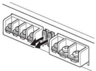
natural_image
Technical line drawing of a multi-chamber electrical connector or socket assembly (no text or symbols)Warning
Never use a fuse with an amperage rating exceeding the one supplied with the unit as this could damage the unit.
Specifications
AUDIO POWER SPECIFICATIONS

CTA2006 Standard
Power Output: 45 Watts RMS × 4 at 4
Ohms, 90 Watts RMS × 2 at 4 Ohms < 1% THD+N
SN Ratio: 83 dBA (FRONT/REAR), 80 dBA
(SUB) (reference: 1 Watt into 4 Ohms)
Wireless Communication
Communication System:
BLUETOOTH Standard version 3.0
Output:
BLUETOOTH Standard Power Class 2 (Max. Conducted +1 dBm)
Maximum communication range ^*1 :
Line of sight approx. 10 m (33 ft)
Frequency band:
2.4 GHz band
(2.4000 GHz - 2.4835 GHz)
Modulation method: FHSS
Compatible BLUETOOTH Profiles ^2 :
A2DP (Advanced Audio Distribution Profile) 1.3
AVRCP (Audio Video Remote Control Profile) 1.5
SPP (Serial Port Profile)
Corresponding codec:
SBC (.sbc), AAC (.m4a)
*1 The actual range will vary depending on factors such as obstacles between devices, magnetic fields around a microwave oven, static electricity, reception sensitivity, antenna (aerial)'s performance, operating system, software application, etc.
*2 BLUETOOTH standard profiles indicate the purpose of BLUETOOTH communication between devices.
General
Circuit system:
Class D Amplifier,
Pulse power supply
Inputs:
RCA pin jacks,
High level input connector
Input level adjustment range (in 6ch mode):
0.3 V - 6 V (RCA pin jacks),
3 V - 12 V (High level input)
Outputs:
Speaker output connector,
WOOFER/SUBWOOFER terminals
Speaker impedance:
4 Ω - 8 Ω (Speaker output connector),
2 Ω - 8 Ω (WOOFER/SUBWOOFER terminals)
Maximum output:
5 Speakers:
100 W × 4 (FRONT/REAR at 4 Ω),
1,100 W × 1 (SUB BTL at 2 Ω)
6 Speakers:
100 W × 4 (FRONT/REAR at 4 Ω),
300 W × 2 (SUB at 2 Ω)
Rated output (supply voltage at 14.4 V, 20 Hz -
20 kHz, 1% THD):
6 Speakers:
45 W × 4 (FRONT/REAR at 4 Ω),
90 W × 2 (SUB at 4 Ω)
Frequency response:
20 Hz - 20 kHz ( ^+0.5_-3.0 ) (FRONT/REAR),
20 Hz - 10 kHz ( ^+0.5_-3.0 ) (SUB)
Harmonic distortion:
0.1% at 1 W, 1 kHz (FRONT/REAR at 4 Ω),
0.1% at 45 W, 1 kHz (SUB at 4 Ω)
Low-pass filter:
500 Hz - 4 kHz, 12 dB/oct (REAR),
50 Hz - 500 Hz, 12 dB/oct (SUB)
High-pass filter:
500 Hz - 4 kHz, 12 dB/oct (FRONT),
50 Hz - 500 Hz, 12 dB/oct (REAR)
Low boost:
0 dB - 10 dB (40 Hz) (SUB)
Power requirements:
12 V DC car battery (negative ground (earth))
Power supply voltage:
10.5 V - 16 V
Current drain:
At rated output: 36 A
45 W × 4 (FRONT/REAR at 4 Ω),
90 W × 2 (SUB at 4 Ω)
ACC Input: 1 mA
Remote input: 1 mA
Dimensions:
Approx. 295 mm × 51 mm × 199.5 mm
(11 5/8 in × 2 1/8 in × 7 7/8 in) (w/h/d) not incl.
projecting parts and controls
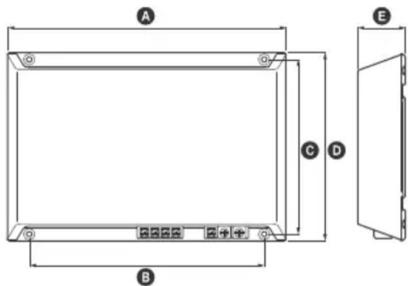
A 295 mm (11 ^5 /8 in)
B 248 mm (97/8 in)
© 184.8 mm (7 ^3 /8 in)
D 199.5 mm (7 7/8 in)
E 51 mm (2 1/8 in)
Mass:
Approx. 2.6 kg (5 lb 12 oz) not incl. accessories
Package contents:
Main unit (1)
Mounting screws (4)
High level input cord (1)
RCA input cord (1)
Speaker output cord (1)
Protection cap (1)
Your dealer may not handle some of the above listed accessories. Please ask the dealer for detailed information.
Design and specifications are subject to change without notice.
Copyrights
The Bluetooth ^® word mark and logos are registered trademarks owned by the Bluetooth SIG, Inc. and any use of such marks by Sony Corporation is under license. Other trademarks and trade names are those of their respective owners.
Apple, iPhone, iPod, and iPod touch are trademarks of Apple Inc., registered in the U.S. and other countries.
Google, Google Play and Android are trademarks of Google LLC.
Troubleshooting
The following checklist will assist in the correction of most problems which you may encounter with your unit. Before going through the checklist below, refer to the connection and operating procedures.
The POWER/PROTECTOR indicator does not light up.
→ The fuse is blown.
- Replace the fuse with a new one.
→ He ground (earth) wire is not securely connected.
- Fasten the ground (earth) wire securely to a metal point of the car.
→ He voltage going into the remote input (REM) terminal is too low.
- Turn on the car audio unit if it is not turned on.
- Use a relay if the system employs too many amplifiers.
→ Check the battery voltage (10.5 V – 16 V).
The POWER/PROTECTOR indicator flashes quickly.
→ Turn off the power switch. The speaker outputs have shorted.
- Rectify the cause of the short.
→ ürn off the power switch. Make sure the speaker cord and ground (earth) wire are securely connected.
The POWER/PROTECTOR indicator flashes slowly (once every second).
→ The thermal protector has activated, and the speaker outputs will be decreased.
- Make sure the impedance of connected speakers is appropriate.
The unit becomes abnormally hot.
→ The unit heats up abnormally.
- Use speakers with suitable impedance: 2 - 8 (stereo), 4 - 8 (when used as a bridging amplifier).
→ Make sure to place the unit in a well ventilated location.
Alternator noise is heard.
→ The power connecting wires are installed too close to the RCA pin cords.
- Keep the wires away from the cords.
→ He ground (earth) wire is not securely connected.
- Fasten the ground (earth) wire securely to a metal point of the car.
→ Negative speaker wires are touching the car chassis.
- Keep the wires away from the car chassis.
The sound is muffled.
→ Check that the filter settings and the cut-off frequency adjustment are appropriate according to the speaker system. For details, see "Input connections" (page 10) and "Speaker connections" (page 14).
The sound is too quiet.
→ The LEVEL adjustment control is not appropriate. Turn the LEVEL adjustment control in the clockwise direction.
BLUETOOTH function
The indicator does not light up.
→ The selected connection mode on the unit is not appropriate. - Check that the SELECT switch is set to the "2V" or "5V" position.
This unit cannot be detected from BLUETOOTH devices.
→ Press PAIRING to set this unit to pairing standby mode before pairing the BLUETOOTH devices.
→ his unit may not be detected from a BLUETOOTH device already connected to other BLUETOOTH devices.
- Operate the BLUETOOTH device to release the connections with other BLUETOOTH devices, then search for this unit.
→ flthe device is already paired, detect this unit from the BLUETOOTH device while the ✗ indicator on the unit is flashing quickly.
Connection is not possible.
→ The connection is controlled from the BLUETOOTH device. - Operate the BLUETOOTH device to connect to this unit.
The device name of this unit does not appear.
→ Depending on the status of the BLUETOOTH device, it may not be possible to obtain the device name of this unit.
The volume of the connected BLUETOOTH device is low (high).
→ Volume level will differ depending on the BLUETOOTH device. - Adjust the volume of the connected BLUETOOTH device or this unit.
The sound skips during playback of a BLUETOOTH device.
→ Reduce the distance between this unit and the BLUETOOTH device.
→ flthe BLUETOOTH device is inside a case which interrupts the signal, remove the case from the BLUETOOTH device during use.
→ Several BLUETOOTH devices or other devices which emit radio waves are in use nearby.
- Turn off the other devices.
- Increase the distance from the other devices.
→ File playback sound stops momentarily when the connection with the cellular phone is being made on the BLUETOOTH device. This is not a malfunction.
This unit cannot be controlled from the BLUETOOTH device.
→ Check that the connected BLUETOOTH device supports AVRCP.
Some functions do not work.
→ Check that the connected BLUETOOTH device supports the functions in question.
Pairing failed due to a timeout.
→ Depending on the connecting BLUETOOTH device, the time limit for pairing may be short. – Try completing the pairing within the time.
Cannot pair.
→ If the pairing information of the unit is on the connecting BLUETOOTH device, the unit may not be able to pair with a previously paired BLUETOOTH device after initializing the unit. In this case, delete the pairing information of the unit from the BLUETOOTH device, and then pair them again.
BLUETOOTH function cannot operate.
→ Turn off the car audio unit, then turn the car audio unit on again.
Sony | Music Center operation
Application name does not match the actual application in "Sony | Music Center".
→ Launch the application again from the "Sony | Music Center" application.
If these solutions do not help improve the situation, consult your nearest Sony dealer.
Support Site
If you have any questions or for the latest support information on this product, please visit the website below:
Customers in the United States/Canada:
Customers in Asia Pacific/Middle East:
http://www.sony-asia.com/section/support
http://www.sony-asia.com/caraudio/
Communication BLUETOOTH
Installation et raccordements
21 Brnes WOOFER/SUBWOOFER
Section POWER :
22 Fable (30 A)
23 Bone ACC (accessoires)
Borne +12V
Borne GND (masse)
Installation et raccordements
natural_image
Technical line drawing of a rectangular electronic device with ports and a circular knob (no text or symbols)Raccordements
Remarque
Raccordements REMOTE
natural_image
Technical line drawing of a multi-chamber electrical connector or socket assembly (no text or symbols)Avertissement
Jumelage impossible.
http://www.sony-asia.com/section/support
http://www.sony-asia.com/caraudio/
23 Arminial ACC (accessoria)
Terminal +12V
Terminal GND (a tierra)
natural_image
Technical line drawing of a rectangular electronic device with mounting points and a central knob (no text or symbols)Conexiones
Nota
flowchart
graph TD
    A["Tweeter (min. 4 Ω)"] --> B["Low Speaker"]
    C["Woofer (min. 4 Ω)"] --> D["Low Speaker"]
    E["Subwoofer (min. 2 Ω)"] --> F["BTL"]
    B --> G["High Pass Filter Off ON"]
    D --> H["Filter Off HPF UPF UPF UPF UPF UPF UPF UPF UPF UPF UPF UPF UPF UPF UPF UPF UPF UPF UPF UPF UPF UPF UPF UPF UPF UPF UPF UPF UPF UPF UPF UPF UPF UPF UPF UPF UPF UPF UPF UPF UPF UPF UPF UPF UPF UPF UPF UPF UPF UPF UPF Upf"]
    G --> I["Switch"]
    H --> J["Switch"]
    I --> K["Switch"]
    J --> L["Switch"]
    K --> M["Switch"]
    L --> N["Switch"]
    M --> O["Switch"]
    N --> P["Switch"]
    O --> Q["Switch"]
    P --> R["Switch"]
    Q --> S["Switch"]
    R --> T["Switch"]
    S --> U["Switch"]
    T --> V["Switch"]
    U --> W["Switch"]
    V --> X["Switch"]
    W --> Y["Switch"]
    X --> Z["Switch"]
    Y --> AA["Switch"]
    Z --> AB["Switch"]
Nota
natural_image
Technical line drawing of a multi-chamber electrical connector or socket assembly (no text or symbols)Advertencia
natural_image
Technical line drawing of a rectangular electronic device with mounting holes and a central knob (no text or symbols)การเชื่อมต่อ
หมายเหตุ
flowchart
graph TD
    A["Speaker L"] --> B["Speaker R"]
    C["Speaker L"] --> D["Speaker R"]
    E["Speaker L"] --> F["Speaker R"]
    G["Speaker L"] --> H["Speaker R"]
    I["Speaker L"] --> J["Speaker R"]
    K["Speaker L"] --> L["Speaker R"]
    M["Speaker L"] --> N["Speaker R"]
    O["Speaker L"] --> P["Speaker R"]
    Q["Speaker L"] --> R["Speaker R"]
    S["Speaker L"] --> T["Speaker R"]
    U["Speaker L"] --> V["Speaker R"]
    W["Speaker L"] --> X["Speaker R"]
    Y["Speaker L"] --> Z["Speaker R"]
    AA["Speaker L"] --> AB["Speaker R"]
    AC["Speaker L"] --> AD["Speaker R"]
    AE["Speaker L"] --> AF["Speaker R"]
    AG["Speaker L"] --> AH["Speaker R"]
    AI["Speaker L"] --> AJ["Speaker R"]
    AK["Speaker L"] --> AL["Speaker R"]
    AM["Speaker L"] --> AN["Speaker R"]
    AO["Speaker L"] --> AP["Speaker R"]
    AQ["Speaker L"] --> AR["Speaker R"]
    AS["Speaker L"] --> AT["Speaker R"]
    AU["Speaker L"] --> AV["Speaker R"]
    AW["Speaker L"] --> AX["Speaker R"]
    AY["Speaker L"] --> AZ["Speaker R"]
    BA["Speaker L"] --> BB["Speaker R"]
    BC["Speaker L"] --> BD["Speaker R"]
    BE["Speaker L"] --> BF["Speaker R"]
    BG["Speaker L"] --> BH["Speaker R"]
    BI["Speaker L"] --> BJ["Speaker R"]
    BK["Speaker L"] --> BL["Speaker R"]
    BM["Speaker L"] --> BN["Speaker R"]
    BO["Speaker L"] --> BP["Speaker R"]
    BZ["Speaker L"] --> CA["Speaker R"]
    CB["Speaker L"] --> CD["Speaker R"]
    CE["Speaker L"] --> CF["Speaker R"]
    CG["Speaker L"] --> CH["Speaker R"]
    CI["Speaker L"] --> CJ["Speaker R"]
    CK["Speaker L"] --> CL["Speaker R"]
    CM["Speaker L"] --> CN["Speaker R"]
    CO["Speaker L"] --> CP["Speaker R"]
    CS["Speaker L"] --> CT["Speaker R"]
    CU["Speaker L"] --> CV["Speaker R"]
    CW["Speaker L"] --> CX["Speaker R"]
    CY["Speaker L"] --> CZ["Speaker R"]
    DA["Speaker L"] --> DB["Speaker R"]
    DC["Speaker L"] --> DD["Speaker R"]
    DJ["Speaker L"] --> DE["Speaker R"]
    DF["Speaker L"] --> DG["Speaker R"]
    DH["Speaker L"] --> DI["Speaker R"]
    DJA["BTL"] --> DJA
    DK["BTL"] --> DK
    LB["BTL"] --> BL
    CC["BTL"] --> CC
    DD["BTL"] --> DD
    DE["BTL"] --> DE
    DL["BTL"] --> DL
    EE["BTL"] --> EE
    FZ["BTL"] --> FZ
    GG["BTL"] --> GG
    BX["BTL"] --> BX
    BY["BTL"] --> BY
    BZ[ACTL/FF/FF/FF/FF/FF/FF/FF/FF/FF/FF/FF/FF/FF/FF/FF/FF/FF/FF/FF/FF/FF/FF/FF/FF/FF/FF/FF/FF/FF/FF/FF/FF/FF/FF/FF/FF/FF/FF/FF/FF/FF/FF/FF/FF/FF/FF/FF/FF/FF/FF/CCY/BTL/ACTL/ACTL/ACTL/ACTL/ACTL/ACTL/ACTL/ACTL/ACTL/ACTL/ACTL/ACTL/ACTL/ACTL/ACTL/ACTL/ACTL/ACTL/ACTL/ACTL/ACTL/ACTL/ACTL/ACTL/ACTL/ACTL/ACTL/ACTL/ACTL/ACTL/ACTL/ACTL/ACTL/ACTL/BTL/ACTL/ACTL/ACTL/ACTL/ACTL/ACTL/ACTL/ACTL/ACTL/ACTL/ACTL/ACTL/ACTL/ACTL/ACTL/ACTL/ACTL/ACTL/ACTL/ACTL/ACTL/ACTL/ACTL/ACTL/ACTL/ACTL/BTL/ACTL/ACTL/ACTL/ACTL/ACTL/ACTL/AACTL/ACTL/ACTL/ACTL/ACTL/ACTL/ACTL/ACTL/ACTL/ACTL/ACTL/ACTL/ACTL/ACTL/ACTL/ACTL/ACTL/ACTL/ACTL/ACTL/BTL/ACTL/ACTL/ACTL/ACTL/ACTL/ACTL/ACTL/ACTL/ACTL/ACTL/ACTL/ACTL/ACTL/BTL/ACTL/ACTL/ACTL/ACTL/ACTL/ACTL/ACTL/ACTL/ACTL/ACTL/BTL/ACTL/ACTL/ACTL/ACTL/ACTL/ACTL/ACTL/ACTL/BTL/ACTL/ACTL/ACTL/ACTL/ACTL/ACTL/ACTL/BTL/ACTL/ACTL/ACTL/ACTL/ACTL/BTL/ACTL/BTL-ACTL/BTL-ACTL/BTL-ACTL/BTL-ACTL/BTL-ACTL/BTL-ACTL/BTL-ACTL/BTL-ACTL/BTL-ACTL/BTL-ACTL/BTL-ACTL/BTL-ACT
หมายเหตุ
"Sony | Music Center"
natural_image
Technical line drawing of a multi-chamber electrical connector or socket assembly (no text or symbols)1,100 W × 1 (SUB BTL η 2 Ω)
ลำโพง 6 ตัว:
100 W × 4 (FRONT/REAR η 4 Ω),
300 W × 2 (SUB η 2 Ω)
14.4 V, 20 Hz – 20 kHz, 1% THD):
ลำโพง 6 ตัว:
45 W × 4 (FRONT/REAR η 4 Ω),
90 W × 2 (SUB η 4 Ω)
การตอบสนองความถี่:
20 Hz - 20 kHz ( ^+0.5_-9.0 (FRONT/REAR),
20 Hz - 10 kHz ( ^+ dB) (SUB)
0.1% η̂ 1 W, 1 kHz (FRONT/REAR η̂ 4 Ω),
90 W × 2 (SUB η 4 Ω)
http://www.sony-asia.com/section/support
http://www.sony-asia.com/caraudio/
http://www.sony-asia.com/section/support
http://www.sony-asia.com/caraudio/
$$ \text { WOOFER / SUBWOOFER } $$
natural_image
Pure technical line drawing of a mechanical or electrical component assembly without any text, numbers, or symbolsAdvanced car audio" [Custom]
("Sony | Music Center" ;1 "setting
(###) [OFF]
"Advanced car audio setting"
کنید.
(محوكنده) Fader
"Advanced car audio setting"
کنید.
natural_image
Illustration of a smartphone, wireless signal waves, and a rectangular electronic device (no text or symbols)natural_image
Illustration of a smartphone, wireless signal waves, and a rectangular electronic device (no text or symbols)" Sony | Music Center"
" Sony | Music Center"
flowchart
graph TD
    A["REMOTE OUT*"] --> B["ACCC"]
    C["REMO"] --> D["RES"]
    E["REMO OUT"] --> F["RES"]
    G["REMO OUT"] --> H["RES"]
    I["REMO OUT"] --> J["RES"]
    K["REMO OUT"] --> L["RES"]
    M["REMO OUT"] --> N["RES"]
    O["REMO OUT"] --> P["RES"]
    Q["REMO OUT"] --> R["RES"]
    S["REMO OUT"] --> T["RES"]
    U["REMO OUT"] --> V["RES"]
    W["REMO OUT"] --> X["RES"]
    Y["REMO OUT"] --> Z["RES"]
    AA["REMO OUT"] --> AB["RES"]
    AC["REMO OUT"] --> AD["RES"]
    AE["REMO OUT"] --> AF["RES"]
    AG["REMO OUT"] --> AH["RES"]
    AI["REMO OUT"] --> AJ["RES"]
    AK["REMO OUT"] --> AL["RES"]
    AM["REMO OUT"] --> AN["RES"]
    AO["REMO OUT"] --> AP["RES"]
    AQ["REMO OUT"] --> AR["RES"]
    AS["REMO OUT"] --> AT["RES"]
    AU["REMO OUT"] --> AV["RES"]
    AW["REMO OUT"] --> AX["RES"]
    AY["REMO OUT"] --> AZ["RES"]
    BA["REMO OUT"] --> BB["RES"]
    BC["REMO OUT"] --> BD["RES"]
    BE["REMO OUT"] --> BF["RES"]
    BG["REMO OUT"] --> BH["RES"]
    BI["REMO OUT"] --> BJ["RES"]
    BK["REMO OUT"] --> BL["RES"]
    BM["REMO OUT"] --> BN["RES"]
    BO["REMO OUT"] --> BP["RES"]
    BQ["REMO OUT"] --> BR["RES"]
    BS["REMO OUT"] --> BT["RES"]
    BU["REMO OUT"] --> BV["RES"]
    BW["REMO OUT"] --> BX["RES"]
    BY["REMO OUT"] --> BZ["RES"]
    CA["REMO OUT"] --> CB["RES"]
    CC["REMO OUT"] --> CD["RES"]
    CE["REMO OUT"] --> CF["RES"]
    DG["REMO OUT"] --> DH["RES"]
    DI["REMO OUT"] --> DJ["RES"]
    DK["REMO OUT"] --> DL["RES"]
    DV["REMO OUT"] --> DW["RES"]
    DX["REMO OUT"] --> DXB["RES"]
    DXB --> DXC["RES"]
    DXC --> DXD["RES"]
    DXD --> DXE["RES"]
    DXE --> DXF["RES"]
    DXF --> DXG["RES"]
    DXG --> DXH["RES"]
    DXH --> DXI["RES"]
    DXI --> DXJ["RES"]
    DXJ --> DXK["RES"]
    DXK --> DXL["RES"]
    DXL --> DXM["RES"]
    DXM --> DXN["RES"]
    DXN --> DXO["RES"]
    DXO --> DXP["RES"]
    DXP --> DXQ["RES"]
    DXQ --> DXR["RES"]
    DXR --> DXS["RES"]
    DXS --> DXT["RES"]
    DXT --> DXU["RES"]
    DXU --> DXV["RES"]
    DXV --> DXW["RES"]
    DXW --> DXX["RES"]
    DXX --> DXY["RES"]
    DXY --> DXZ["RES"]
توجه
natural_image
Technical line drawing of a rectangular electronic device with ventilation slots and a circular component (no text or symbols)http://www.sony-asia.com/section/support
http://www.sony-asia.com/caraudio/
.BLUTOOTH Teptog in the source of the source.
natural_image
Pure technical line drawing of a multi-chamber electrical connector (no text or symbols)Advanced car audio" (physically) [Custom]
("Sony | Music Center" لتطبيق "setting (عدم ضبط أي وضع) [OFF]
Advanced car" Healthcare ب Minority "BAL/FAD/SW Level"
."audio setting
natural_image
Illustration of a smartphone and a wireless device with signal waves (no text or symbols)natural_image
Illustration of a smartphone, wireless signal waves, and a rectangular electronic device (no text or symbols)2 underscores receives an airport, including the largest passenger in PAIRING.
flowchart
graph TD
    A["L"] --> B["②"]
    C["R"] --> B
    D["①"] --> E["High Pass Filter OFF ON"]
    F["②"] --> G["High Pass Filter HPF LPF"]
    H["③"] --> I["Low Pass Filter OFF ON"]
    J["④"] --> K["Low Pass Filter HPF LPF"]
    L["⑤"] --> M["Low Pass Filter OFF ON"]
    N["⑥"] --> O["Low Pass Filter HPF LPF"]
    P["⑦"] --> Q["Low Pass Filter OFF ON"]
    R["⑧"] --> S["Low Pass Filter HPF LPF"]
    T["⑨"] --> U["Low Pass Filter OFF ON"]
    V["⑩"] --> W["Low Pass Filter HPF LPF"]
    X["⑪"] --> Y["Low Pass Filter OFF ON"]
    Z["⑫"] --> AA["Low Pass Filter HPF LPF"]
    AB["⑬"] --> AC["Low Pass Filter OFF ON"]
    AD["⑭"] --> AE["Low Pass Filter HPF LPF"]
    AF["⑮"] --> AG["Low Pass Filter OFF ON"]
    AH["⑯"] --> AI["Low Pass Filter HPF LPF"]
    AJ["⑰"] --> AK["Low Pass Filter OFF ON"]
    AL["⑱"] --> AM["Low Pass Filter HPF LPF"]
    AN["㉑"] --> AO["Low Pass Filter OFF ON"]
    AP["㉒"] --> AQ["Low Pass Filter HPF LPF"]
    AR["㉔"] --> AS["Low Pass Filter OFF ON"]
    AT["㉕"] --> AU["Low Pass Filter HPF LPF"]
    AV["㉚"] --> AW["Low Pass Filter OFF ON"]
    AX["㉟"] --> AY["Low Pass Filter HPF LPF"]
ملاحظة
ON :LOW PASS FILTER -
توصيل سلك السماعة
ON:LOW PASS FILTER -
وصلات семاعة
."Sony | Music Center"
D وصلة داخل عالي مستوى (2ch ∪ وضع/DSP) ∩ (13 ∪ ∪ ∪ ∪ ∪ ∪ ∪ ∪ ∪ ∪ ∪ ∪ ∪ ∪ ∪ ∪ ∪ ∪ ∪ ∪ ∪ ∪ ∪ ∪ ∪ ∪ ∪ ∪ ∪ ∪ ∪ ∪ ∪ ∪ ∪ ∪ ∪ ∪ ∪ ∪ ∪ ∪ ∪ ∪ ∪ ∪ ∪ ∪ ∪ ∪ ∮
flowchart
graph TD
    A["客户端"] --> B[" SMS/Message"]
    B --> C[" Arabic (يسرال)"]
    B --> D[" Chinese (يسرال)"]
    B --> E[" Portuguese (يسرال)"]
    C --> F[" SMS/Message"]
    D --> G[" Chinese (يسرال)"]
    E --> H[" Portuguese (يسرال)"]
    F --> I[" ④ "]
    G --> J[" ④ "]
    H --> K[" ④ "]
flowchart
graph TD
    A["Front Audio OUT"] --> B["FRONT AUDIO IN"]
    A --> C["REAR AUDIO IN"]
    D["REAR AUDIO OUT*"] --> E["RCA كابل موزع (غير مرفقة)"]
    B --> F["3"]
    C --> G["SUB AUDIO IN"]
    E --> H["SELECT 5V 2V 8ch 2m/8T"]
    F --> I["面板1"]
    G --> J["面板2"]
    H --> K["面板3"]
."Sony | Music Center"
flowchart
graph TD
    A["REMOTE OUT*"] --> B["ACCC"]
    C["RESM"] --> D["ACCC"]
    E["APSICUM 4"] --> F["ACCC"]
    G["AMSUNG"] --> H["ACCC"]
    I["RESAUX"] --> J["ACCC"]
    K["RESAUX"] --> L["ACCC"]
    M["RESAUX"] --> N["ACCC"]
    O["RESAUX"] --> P["ACCC"]
    Q["RESAUX"] --> R["ACCC"]
    S["RESAUX"] --> T["ACCC"]
    U["RESAUX"] --> V["ACCC"]
    W["RESAUX"] --> X["ACCC"]
    Y["RESAUX"] --> Z["ACCC"]
    AA["RESAUX"] --> AB["ACCC"]
    AC["RESAUX"] --> AD["ACCC"]
    AE["RESAUX"] --> AF["ACCC"]
    AG["RESAUX"] --> AH["ACCC"]
    AI["RESAUX"] --> AJ["ACCC"]
    AK["RESAUX"] --> AL["ACCC"]
    AM["RESAUX"] --> AN["ACCC"]
    AO["RESAUX"] --> AP["ACCC"]
    AQ["RESAUX"] --> AR["ACCC"]
    AS["RESAUX"] --> AT["ACCC"]
    AU["RESAUX"] --> AV["ACCC"]
    AW["RESAUX"] --> AX["ACCC"]
    AY["RESAUX"] --> AZ["ACCC"]
    BA["RESAUX"] --> BB["ACCC"]
    BC["RESAUX"] --> BD["ACCC"]
    BE["RESAUX"] --> BF["ACCC"]
    BG["RESAUX"] --> BH["ACCC"]
    BI["RESAUX"] --> BJ["ACCC"]
    BK["RESAUX"] --> BL["ACCC"]
    BM["RESAUX"] --> BN["ACCC"]
    BO["RESAUX"] --> BP["ACCC"]
    BQ["RESAUX"] --> BR["ACCC"]
    BS["RESAUX"] --> BT["ACCC"]
    BU["RESAUX"] --> BV["ACCC"]
    BW["RESAUX"] --> BX["ACCC"]
    BY["RESAUX"] --> BZ["ACCC"]
    CA["RESAUX"] --> CB["ACCC"]
    CC["RESAUX"] --> CD["ACCC"]
    CE["RESAUX"] --> CF["ACCC"]
    CG["RESAUX"] --> CH["ACCC"]
    CI["RESAUX"] --> CJ["ACCC"]
    CK["RESAUX"] --> CL["ACCC"]
ملاحظة
natural_image
Technical line drawing of a rectangular electronic device with mounting points and a central knob (no text or symbols)التركيب والوصلات
Class-D Amplifier with DSP

Bluetooth®
Made for
iPhone | iPod
http://www.sony.net/
©2018 Sony Corporation Printed in Thailand