
STRZA2000ES - AV receiver SONY - Free user manual and instructions
Find the device manual for free STRZA2000ES SONY in PDF.
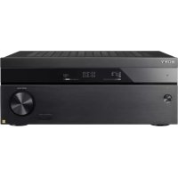
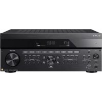
| Product type | Audio-video receiver |
| Brand | Sony |
| Model | STR-ZA2000ES |
| Channels | 7.2 (front, center, surround, surround back/front height) |
| Output power | Not specified in the manual |
| HDMI inputs | 8 (BD/DVD, SAT/CATV, GAME, STB, VIDEO, AUX, TV, SA-CD/CD) |
| HDMI outputs | 2 (HDMI OUT A and B) |
| HDCP compatibility | HDCP 2.2 on SAT/CATV input and output A |
| Video resolution | Up to 4K (with 4K upscaling) |
| Audio formats | Dolby Digital, DTS, PCM, DSD (main zone only) |
| Auto calibration | Digital Cinema Auto Calibration (D.C.A.C.) with optimization microphone |
| Multi-zone | Main zone, Zone 2 (amplified or line), Zone 3 (line) |
| Network connection | Ethernet (RJ45), Wi-Fi not specified |
| Network standby mode | Yes (adjustable) |
| Audio streaming | Music Connect (link with Hi-Fi system) |
| Firmware update | Via USB key (front USB port) |
| External control | RS232C, IP (web configuration), PING button |
| Analog audio inputs | RCA (multiple), optical, coaxial |
| Speaker outputs | Terminals for 5.1 + surround back/front height/Zone 2 |
| Pre-outs | Zone 2 and Zone 3 (fixed/variable) |
Frequently Asked Questions - STRZA2000ES SONY
User questions about STRZA2000ES SONY
0 question about this device. Answer the ones you know or ask your own.
Ask a new question about this device
Download the instructions for your AV receiver in PDF format for free! Find your manual STRZA2000ES - SONY and take your electronic device back in hand. On this page are published all the documents necessary for the use of your device. STRZA2000ES by SONY.
USER MANUAL STRZA2000ES SONY
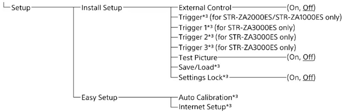
Menu items underlined are default settings.
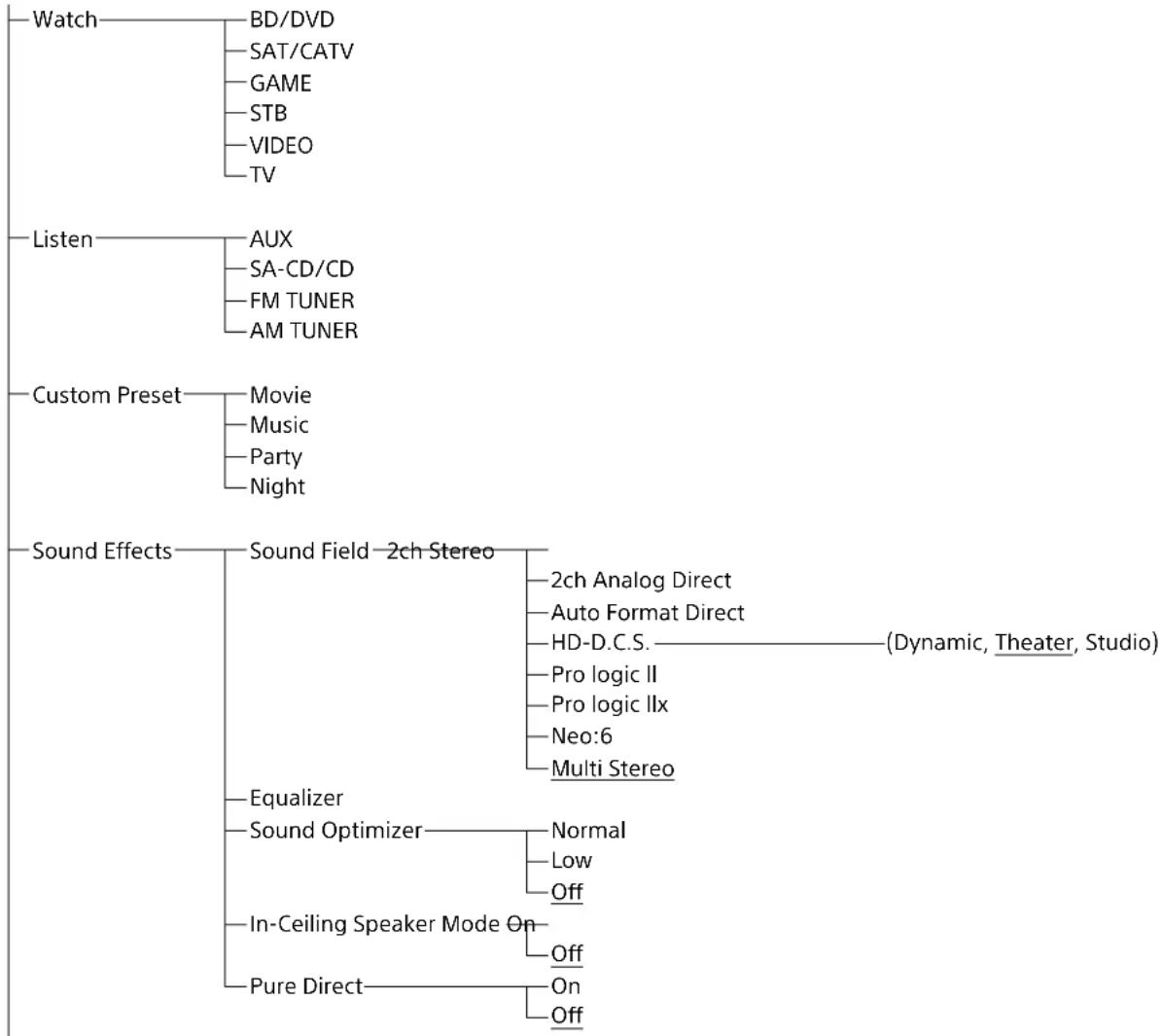
Home
| Setup | Input Setup*1 *2 | Icon |
| Name | ||
| Watch/Listen | ||
| Show/Hide | ||
| HDMI | ||
| OPTICAL/COAXIAL | ||
| COMPONENT | ||
| VIDEO IN | ||
| AUDIO IN | ||
| Input Mode | ||
| Preset Sound Field | ||
| In-Ceiling Speaker Mode | ||
| A/V Sync | ||
| Subwoofer Low Pass Filter | ||
| Subwoofer Level | ||
| Trigger (for STR-ZA2000ES/STR-ZA1000ES only) | ||
| Trigger 1 (for STR-ZA3000ES only) | ||
| Trigger 2 (for STR-ZA3000ES only) | ||
| Trigger 3 (for STR-ZA3000ES only) | ||
| Speaker Setup | Auto Calibration*3 | |
| Automatic Phase Matching——(Auto, Off) | ||
| Calibration Type——(Full Flat, Engineer, Front Reference, Off) | ||
| Speaker Pattern | ||
| SB Speaker Assign——(Zone2, Bi-Amp, Front B, Off) | ||
| Size*4——(Large, Small) | ||
| Distance*4——(32 ft 9 in, 32 ft 8 in, ..., 9 ft 10 in, ..., 6 ft 7 in, 6 ft 6 in) | ||
| Level*4——(+10.0dB, +9.5dB, ..., 0.0dB, ..., -9.5dB, -10.0dB) | ||
| Test Tone*3 | ||
| Crossover Frequency*4——(40Hz, 50Hz, ..., 120Hz, ..., 190Hz, 200Hz) | ||
| Equalizer*4——(+10.0dB, +9.5dB, ..., 0.0dB, ..., -9.5dB, -10.0dB) | ||
| Center Speaker Lift Up——(10, 9, 8, ..., 2, 1, Off) | ||
| Ceiling Speaker Height——(32 ft 9 in, 32 ft 8 in, ..., 9 ft 0 in, ..., 6 ft 7 in, 6 ft 6 in) | ||
| Distance Unit——(feet, meter) | ||
| Network Setup | Internet Setup*3 | |
| Information*3 | ||
| Network Standby——(On, Off) | ||
| Music Connect——Connected Device | ||
| Input for Music Connect | ||
| Setup | Audio Setup | Digital Legato Linear——(Auto1, Auto2, Off)Sound Optimizer——(Normal, Low, Off)Sound Field*3HD-D.C.S. Type——(Dynamic, Theater, Studio)In-Ceiling Speaker Mode——(On, Off)Pure Direct——(On, Off)Subwoofer Low Pass Filter——(On, Off)A/V Sync——(300 ms, 290 ms, ..., 10 ms, 0 ms,HDMI Auto)Dual Mono——(Main, Sub, Main/Sub)Dynamic Range Compressor——(Auto, On, Off) |
| HDMI Setup | 4K Scaling——(Auto, Off)Control for HDMI——(On, Off)Pass Through——(Auto, On, Off)Audio Out——(AMP, TV+AMP)Zone2 Audio Out——(AMP, Zone2 TV+AMP, Zone2 AMP)Subwoofer Level——(Auto, +10dB, 0dB)HDMI Out B Mode——(Main, Zone2)Priority——(Main&Zone2, Main Only)Fast View——(Auto, Off) | |
| Zone Setup | Main Preset Volume——(+23.0dB, +22.5dB, ..., -92.0dB, -∞dB,Off)Zone2 Power——(On, Off)Zone2 Input——(SOURCE, BD/DVD, ..., FM TUNER,AM TUNER)Zone2 Volume——(+23.0dB, +22.5dB, ..., -40.0dB, ..., -92.0dB, -∞dB)Zone2 Preset Volume——(+23.0dB, +22.5dB, ..., -92.0dB, -∞dB,Off)Zone2 Line Out——(Variable, Fixed)Zone3 Power——(On, Off)Zone3 Input——(SOURCE, VIDEO, ..., FM TUNER,AM TUNER)Zone3 Volume——(+23.0dB, +22.5dB, ..., -40.0dB, ..., -92.0dB, -∞dB)Zone3 Preset Volume——(+23.0dB, +22.5dB, ..., -92.0dB, -∞dB,Off)Zone3 Line Out——(Variable, Fixed) | |
| System Setup | Language — (English, Espanol, Francais,)Auto Display——(On, Off)Auto Standby——(On, Off)Volume Display——(Relative, Absolute)Dimmer——(100%, 60%, 0%)Sleep——(2:00:00, 1:30:00, 1:00:00, 0:30:00,Off)Software VersionUSB Update*3Tuner Setup*3 FM ModeName Input |
1 You can select the following inputs in Input Setup screen.
BD/DVD, SAT/CATV, GAME, STB, VIDEO, AUX, TV, SA-CD/CD
2 You can set up each input using these menu items in Input Setup.
3 Detailed information of these menu items is displayed after you select the settings.
4 The menu item can be adjusted against each speaker.
Table of Contents
Map of GUI Menu System 2
Using the home menu. 2
Connections & settings (multi room/single room)
Preparing the receiver. 7
Outline dimensional drawing. 7
Attaching/removing the front cover. 7
Setting up the receiver 7
Connecting equipment 8
Connecting a 4K TV that supports HDCP 2.2 to a 4K streaming box using a 4K-compatible HDMI cable................................8
Linking with a Hi-Fi music system 11
Making a connection for PoE (Power over Ethernet) (for STR-ZA3000ES only). 12
Making a multi-zone connection 13
Mixing separate audio/video inputs (Last video mode) 13
Setting up the receiver. 14
Outputting a test tone from each speaker (Test Tone) 14
Displaying a test screen (Test Picture) 14
Adjusting the sound balance automatically (Auto Calibration) 14
List of messages after Auto Calibration measurements 15
Saving/ loading settings of the receiver 15
Updating the firmware with a USB flash drive. 15
Setting up through a web browser 16
Using the PING button 16
Using the hidden commands
Performing commands using the receiver 17
Performing commands using the supplied remote control 18
Turning on transmitting mode of the discrete code for the main zone ... 18
Turning on transmitting mode of the discrete code for zone2/zone3 ....19
Accessories
Mounting the receiver using the rack mount kit. 20
Others
Zone distribution 21
In-Ceiling Speaker mode 22
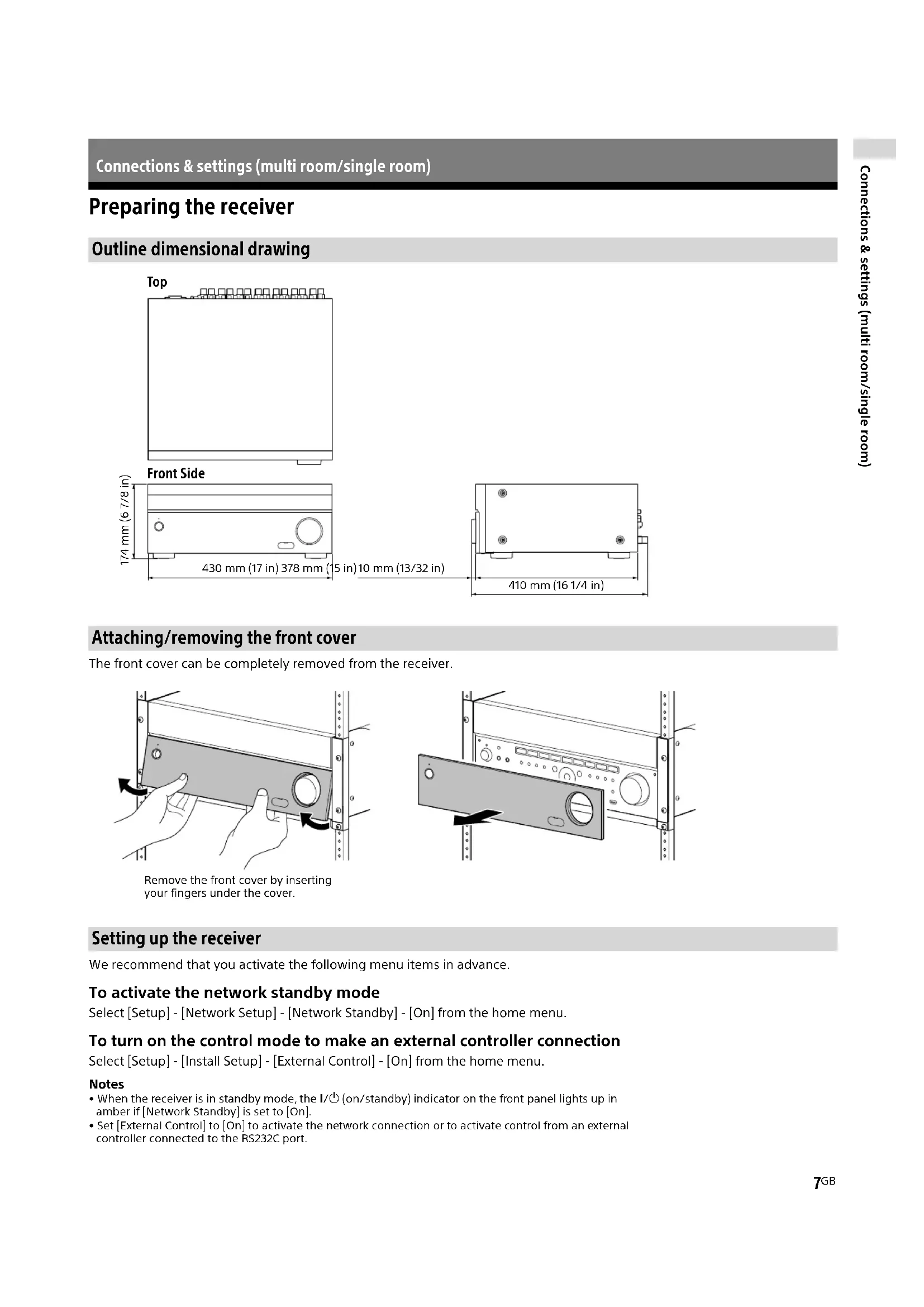
Preparing the receiver
Outline dimensional drawing
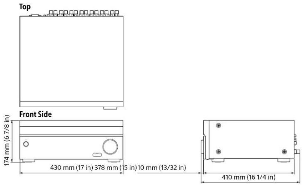
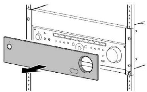
Attaching/removing the front cover
The front cover can be completely removed from the receiver.
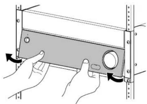
Remove the front cover by inserting your fingers under the cover.
Setting up the receiver
We recommend that you activate the following menu items in advance.
To activate the network standby mode
Select [Setup] - [Network Setup] - [Network Standby] - [On] from the home menu.
To turn on the control mode to make an external controller connection
Select [Setup] - [Install Setup] - [External Control] - [On] from the home menu.
Notes
- When the receiver is in standby mode, the I/O (on/standby) indicator on the front panel lights up in amber if [Network Standby] is set to [On].
- Set [External Control] to [On] to activate the network connection or to activate control from an external controller connected to the RS232C port.
Connecting equipment
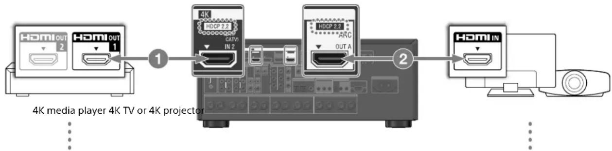
Connecting a 4K TV that supports HDCP 2.2 to a 4K streaming box using a 4K-compatible HDMI cable
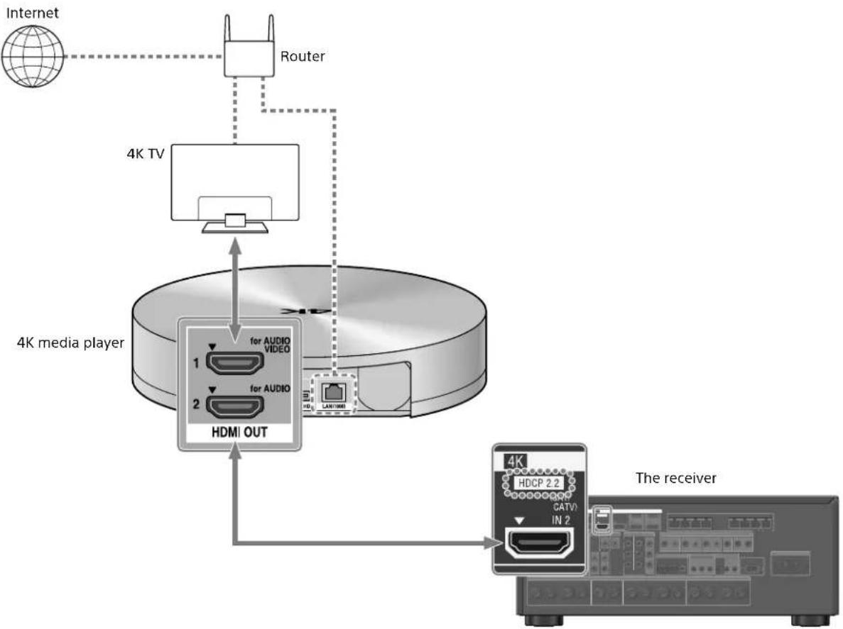
To enjoy audio from 4K content such as 4K movies, connect the HDMI OUT/IN jacks of each device that supports HDCP 2.2^* using HDMI cables, as illustrated below.
- HDCP 2.2 (High-bandwidth Digital Content Protection 2.2) is newly enhanced copyright protection technology that is used to protect content such as 4K movies from Studios.
If you are using a 4K media player other than FMP-X10/X5/X1:
Connect the cable to one of the HDCP 2.2 compatible HDMI OUT jacks. For details, refer to the operation manual supplied with your player.
If you are using an FMP-X10/X5 Media Player:
Connect the receiver to a 4K media player using a High Speed HDMI cable (not supplied).
Connect the cable to the HDMI OUT 1 (for AUDIO VIDEO) jack of the player.
Select [Settings] - [Sound] - [Audio from HDMI OUT]
- [HDMI OUT 1] in the Home menu of the FMP-X10/X5 Media Player after Initial Setup is complete.
Connect the receiver to your 4K TV using a High Speed HDMI cable (not supplied).
If you are using a BRAVIA TV with the series name X950B, X900B or X850B:
Connect the cable to the HDMI IN 1 jack of your TV.
If you are using a different 4K TV or 4K projector:
Connect to one of the HDCP 2.2 compatible HDMI IN jackets. If the jack is not compatible with the ARC (Audio Return Channel) function, also connect an optical digital cable. For details, refer to the operation manual supplied with your 4K TV or 4K projector.
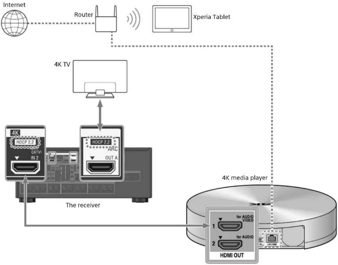
If you are using an FMP-X1 Media Player:
If you are using an FMP-X1 Media Player, connect your FMP-X1 with the receiver in either connection pattern 1 or 2 noted below.
Connection pattern 1
Important:
- An Xperia Tablet is required to use this connection.
- Supported Xperia Tablet models are Xperia Tablet S, Xperia Tablet Z and Xperia Tablet Z2.
- Customers without an Xperia Tablet will need to purchase one to use this connection.
- Before use, download the "4K Ultra HD Remote" Android application for operating the FMP-X1 from an Xperia Tablet.
"4K Ultra HD Remote" Android application for operating the FMP-X1
You can search for this application at the Google PlayTM Store in the same way as for general Android applications.
Search by the name "4K Ultra HD Remote."
For details, refer to the below website.
https://us.en.kb.sony.com/app/answers/detail/a_id/44331/~/how-to-use-the-4k-ultra-hdremote-app-for-sony-tablet.
Use the HDCP 2.2 compatible HDMI In jack of the 4K Bravia TV as noted below
If you are using XBR-55X900A, XBR-65X900A or XBR-84X900, please confirm its compatibility with your 4K media player on the following website:
https://www.4kactivation.com/
| Model name HDMI In jack |
| XBR-xxX850A HDMI In 4 |
| XBR-xxX900A HDMI In 4 |
| XBR-84X900 HDMI In 2 |
| XBR-xxX950B HDMI In 1 or HDMI In 2 |
| XBR-xxX850B HDMI In 1 or HDMI In 2 |
| XBR-xxX900B HDMI In 1 or HDMI In 2 |
| Other Models Please refer to the specifications of your 4K Bravia TV for its HDCP 2.2compatible jack. |
HDCP 2.2 compatible HDMI jacks of the receiver
The HDCP 2.2 compatible HDMI jacks of the receiver are marked as "HDCP 2.2." Also see the below table.
| Model name HDMI In jacks HDMI Out jacks |
| STR-ZA3000ES SAT/CATV, STB OUT A, OUT B |
| STR-ZA2000ES SAT/CATV OUT A |
| STR-ZA1000ES SAT/CATV OUT A |
1 Connect the HDMI OUT 1 jack of your FMP-X1 with the HDCP 2.2 compatible HDMI IN jack of the receiver.
2 Connect the HDMI OUT jack of the receiver with the HDCP 2.2 compatible HDMI IN jack of 4K Bravia TV.
If the 4K Bravia TV's HDMI In jack is not compatible with the ARC (Audio Return Channel) function, also connect an optical digital cable.
Connection pattern 2
Use the HDCP 2.2 compatible HDMI In jack of the 4K Bravia TV as noted below
If you are using XBR-55X900A or XBR-65X900A, please confirm its compatibility with your 4K media player on the following website:
https://www.4kactivation.com/
| Model name HDMI In jack |
| XBR-xxX850A HDMI In 4 |
| XBR-xxX900A HDMI In 4 |
| XBR-84X900 Please use Connection pattern 1 with an Xperia Tablet |
| XBR-xxX950B HDMI In 2 |
| XBR-xxX850B HDMI In 2 |
| XBR-xxX900B HDMI In 2 |
| Other Models Please refer to the FMP-X1 support web page (below) for details: |
http://esupport.sony.com/US/p/model-home.pl?mdl FMPX1&template_id = 1 ®ion id = 1 &tab manuals#/manualsTab
1 Connect the HDMI OUT 1 jack of your FMP-X1 with the HDCP 2.2 compatible HDMI IN jack of 4K Bravia TV.
2 Connect the HDMI OUT 2 jack of your FMP-X1 with the HDMI IN jack of the receiver.
To output audio from HDMI OUT 2 of the FMP-X1, you need to complete settings as noted below:
https://us.en KB.sony.com/app/answers/detail/a_id/43404/p/47329,82420,85498/c/65,66/kw/receiver
Linking with a Hi-Fi music system
This receiver can switch its power and input automatically by linking with playback operation of the Hi-Fi music system.
Configure settings to enable the receiver to operate linked with a Hi-Fi System device.
1 Select [Setup] - [Network Setup] - [Music Connect] from the home.
2 Select the setting you want.
Connected Device: Select the connected device to enable the function.
Input for Music Connect: Select the input to link with.
3 Start playback on the player device.
The receiver will be turned on and the input switched automatically.
To disable Music Connect
Select [Setup] - [Network Setup] - [Music Connect] - [Connected Device] - [Remove Connected Device] from the home menu.
Notes
The Music Connect feature can be linked only with the power source and input of the main zone. This feature does not link with zone 2 or zone 3.
- The link feature of Music Connect may not work correctly depending on factors such as the specifications of the connected device.
- We recommend that you set [Network Standby] to [On] to activate the feature for linking with Music Connect even if the receiver is in standby mode.
- Only one Hi-Fi music system device can be linked with the receiver at a time using the Music Connect feature.
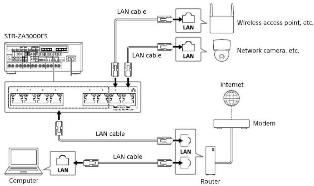
Making a connection for PoE (Power over Ethernet) (for STR-ZA3000ES only)
The following illustration is an example of configuration of a home network with the receiver and a computer.
Notes
- Connect a router to one of ports 1 to 8 on the receiver using a single LAN cable. Do not connect the same router to the receiver using more than one LAN cable. Doing so may cause a malfunction.
- Ports No. 1 and No. 2 support PoE (Power over Ethernet, Alternative A). If you connect a PoE-compatible device to one of these ports, power will be supplied to the device from the receiver.
- You can also connect a device that does not support PoE to the PoE port.
- The PoE port lights in red while supplying power.
This receiver supports PoE Class 3.
Making a multi-zone connection
This receiver allows various multi-zone connections.
Sample setup
| Output jack Connected device Connection method | ||
| HDMI OUT A TV Connection: Connect to the TV using the HDMI OUT A jack. Operation of the receiver: Press HDMI OUT to select HDMI A. | ||
| HDMI OUT B TV Connection: Connect to the TV using the HDMI OUT B jack. Setup menu: Select [Setup] - [HDMI Setup] - [HDMI Out B Mode] - [Zone2] from the home menu. Select [Setup] - [HDMI Setup] - [Zone2 Audio Out] - [Zone2 TV + AMP] from the home menu. | ||
| SPEAKERS terminals FRONT A CENTER SURROUND | 5ch speakers and 1 or 2 subwoofer(s) | Connection: Connect the speakers and subwoofer(s). Setup menu: Perform Auto Calibration and set the following settings. Select [Setup] - [Speaker Setup] - [SB Speaker Assign] - [Zone2] from the home menu. Tip • Select [Setup] - [Input Setup] - [In-Ceiling Speaker Mode] - [On] when you use the in-ceiling speakers. |
| SPEAKERS terminals SURROUND BACK (assigned ZONE2) | 2ch speakers Connection: Connect Zone 2 L/R speakers. Setup menu: Perform Auto Calibration and set the following settings. Select [Setup] - [Speaker Setup] - [SB Speaker Assign] - [Zone2] from the home menu. | |
Mixing separate audio/video inputs (Last video mode)
The receiver can continuously output the input video image used most recently when an audio-only input source is selected.
1 Connect the desired background music source to an input by analog, optical, or coaxial cable. Or use the built-in tuner.
2 Set the input to the following in the Input Setup menu.
HDMI: [None]
Component: [None]
Composite: [---]
Audio: The input connected to the source.
When using the built-in tuner, set the screen mode to [Simple] using the options menu in [FM/AM Display].
Example
Press SAT/CATV followed by TUNER to listen to sound from the built-in tuner while watching a video source connected to SAT/CATV.
The audio output changes to that of the tuner source while SAT/CATV video output is retained.
Setting up the receiver
Outputting a test tone from each speaker (Test Tone)
You can output a test tone from each speaker in sequence.
1 Select [Setup] - [Speaker Setup] - [Test Tone] from the home menu.
2 Select the setting you want. Off
Auto: The test tone is output from each speaker in sequence.
Front L, Center, Front R, Surround R, Surround L, Sur Back*, Sur Back L, Sur Back R, Front High L, Front High R, Subwoofer: You can select which speakers will output the test tone.
- [Sur Back] appears when only one surround back speaker is connected.
3 Adjust the speaker level.
Tips
- You can set a test tone by pressing the TEST TONE button on the remote control. In this case, you can only use the display panel for the operation.
To adjust the level of all speakers at the same time, press + / - You can also use MASTER VOLUME on the receiver.
The adjusted value is shown on the TV screen while adjusting.
Displaying a test screen (Test Picture)
Display a test screen for HDMI OUT A and HDMI OUT B jacks.
1 Press TEST PICTURE on the remote control.
Tips
- A test picture is output from HDMI OUT A at a resolution that corresponds to the specifications of the connected TV. A test picture is output in 480p from HDMI OUT B.
- HDMI audio signals are not output while the test screen is displayed.
Adjusting the sound balance automatically (Auto Calibration)
This receiver is equipped with a D.C.A.C. (Digital Cinema Auto Calibration) function, which allows you to perform automatic calibration.
Auto Calibration allows you to perform automatic calibration as follows.
- Check the connection between each speaker and the receiver.
- Adjust the speaker level.
- Measure the distance of each speaker from your seating position.*1
- Measure the speaker size.*1
- Measure the frequency characteristics (EQ).*1
- Measure the frequency characteristics (Phase).*1 *2
^1 The measurement result is not utilized when [2ch Analog Direct] is selected.
2 The measurement result may be not utilized, depending on the audio formats.
Note
- The D.C.A.C. is designed to achieve proper sound balance for your room. However, you can adjust the speaker levels manually according to your preference using Test Tone.
1 Set up each speaker correctly, and then connect the optimizer microphone.
2 Select [Setup] - [Speaker Setup] - [Auto Calibration] from the home menu.
3 Follow the instructions on the TV screen, then press to select [Start].
Measurement starts in 5 seconds.
The measurement process will take approximately 30 seconds with a test tone.
When measurement ends, a beep sounds and the screen switches.
4 Select the item you want.
5 Save the measurement results.
Select [Save] in step 4.
Calibration Matching
When Auto Calibration is executed, this function works automatically to match the distance and level of the right and left speakers. You can set this function only after the D.C.A.C. measurement process has been completed and the results of D.C.A.C. measurement are saved. The setting is valid until you change it.
Note
- If an error code or warning message appears on the screen in step 3, see "List of messages after Auto Calibration measurements."
Tips
-
You can also perform automatic calibration by pressing the AUTO CAL button on the remote control. If you use the AUTO CAL button, the following restrictions apply to the operation:
-
Prior settings relating to the Auto Calibration will be skipped.
-
You can only use the display panel for the operation.
-
The Auto Calibration function will be canceled if you perform the following during the measurement process:
Turn the receiver on or off.
- Press the input buttons on the remote control or on the receiver.
-Press
- Press SPEAKERS on the receiver.
- Press HDMI OUTPUT.
- Press AMP MENU.
- Press HOME
-Press AUTO CAL
- Change the volume level.
List of messages after Auto Calibration measurements
Code 31:
Front speakers are not selected properly. Select the front speakers using SPEAKERS, and then perform Auto Calibration again.
Code 32, Code 33:
- Speakers were not detected or not connected properly.
- None of the front speakers are connected or only one front speaker is connected.
-
Either the surround left or surround right speaker is not connected.
-
A surround back speaker is connected only to the SPEAKERS SURROUND BACK/FRONT HIGH/FRONT B/BI-AMP/ZONE 2 R terminal. If connecting only one surround back speaker, connect it to the SPEAKERS SURROUND BACK/FRONT HIGH/FRONT B/BI-AMP/ZONE 2 L terminal.
- Either the front high left or front high right speaker is not connected.
The optimizer microphone is not connected. Make sure that the optimizer microphone is connected properly, and then perform Auto Calibration again. If the optimizer microphone is connected properly but the error code still appears, the optimizer microphone cable may be damaged.
- Warning 40:
The measurement process has been completed and a high noise level has been detected. You may be able to achieve better results if you try the process again in a quiet environment.
- Warning 41, Warning 42:
The input from the microphone is too large. The distance between the speaker and the microphone may be too small. Set them further apart, and then perform the measurement again.
- Warning 43:
The distance and position of a subwoofer cannot be detected. This may be caused by noise. Try performing the measurement in a quiet environment.
- NO WARNING:
There is no warning information.
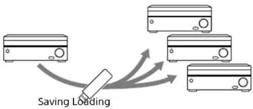
Saving/ loading settings of the receiver
You can save the settings to a USB flash drive and restore the saved settings to the receiver or to another receiver of the same model.
To save the settings
Insert a USB flash drive to the USB port on the front panel of the receiver.
Select [Setup] - [Install Setup] - [Save/Load] - [Save] from the home menu.
To load the settings
Insert to the USB port on the front panel of the receiver a USB flash drive on which the settings are saved.
Select [Setup] - [Install Setup] - [Save/Load] - [Load] from the home menu.
Updating the firmware with a USB flash drive
Make sure to perform the following steps when a firmware update is delivered.
You can download the update firmware from the following website.
http://www.sony.com/essupport
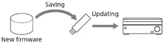
1 Copy the file for updating to the top level directory (just under the root directory) of the USB flash drive (FAT16 or FAT32 with more than 100 MB of free space).
2 Turn the receiver on.
3 Insert the USB flash drive into the USB port on the front panel of the receiver.
4 Select [Setup] - [System Setup] - [USB Update] from the home menu.
[UPDATING...XXX%] will be displayed on the front display. The receiver will automatically reboot after the update completes.
Note
It takes up to 50 minutes for the update to complete.
Setting up through a web browser
The receiver provides a web browser interface for configuring settings.
The PING feature is useful for checking your IP address quickly.

Open a web browser on your computer or mobile device on the same network with the receiver, and then access
http://[receiver's ip-address]/
Using the PING button
The receiver provides the following functions simply by pressing the PING button on the front panel of the receiver.
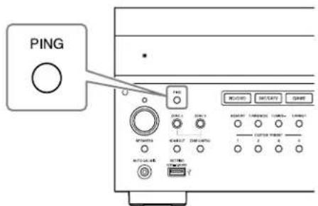
The receiver sends specific UDP multicast or broadcast packets to establish a network connection.
| Protocol Protocol owner |
| SDDP Control4 |
| The receiver displays its IP information on the front display as follows. |
| Information |
| 1 IP address |
| 2 MAC address |
Performing commands using the receiver
This receiver allows you to perform various commands using buttons on the front panel.
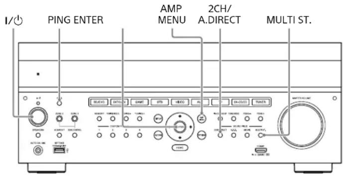
| Function Operation | |
| User initialize (Memory Clear) | Hold I/0 for 5 seconds in standby mode. |
| Sound Field Clear | Hold down MULTI.ST. and press I/0 in standby mode. |
| Settings Lock Hold down PING and AMP MENU and press ENTER while the receiver is turned on. | |
| Command mode | Hold down 2CH/A.DIRECT and press I/0 in standby mode. |
Performing commands using the supplied remote control
This receiver allows you to perform various commands using the supplied remote control.
Turning on transmitting mode of the discrete code for the main zone
While holding down MAIN, press INPUT MODE on the remote control for 5 seconds.
Transmitting mode of the discrete code for the main zone is activated when MAIN starts flashing.
Command list in transmitting mode of the discrete code for the main zone
| Key name Transmitting mode of the discrete code (main) | |
| Code name | |
| HDMI OUTPUT HDMI OUTPUT | |
| ZONE2 I/° | POWER ON (ZONE2) |
| ZONE3 I/° | POWER ON (ZONE3) |
| MAIN I/° | POWER ON |
| ZONE 2 (illuminated in red) | ZONE 2 |
| ZONE 3 (illuminated in red) | ZONE 3 |
| MAIN (illuminated in red) | MAIN |
| BD/DVD 1 | |
| SAT/CATV 2 | |
| GAME 3 | |
| STB 4 | |
| VIDEO 5 | |
| AUX 6 | |
| TV | 7 |
| SA-CD/CD 8 | |
| TUNER 9 | |
| SOUND OPTIMIZER 10/0 | |
| PURE DIRECT 11/* | |
| IN-CEILING SP MODE 12/# | |
| CUSTOM PRESET 1 | PARTY MODE ON/OFF |
| CUSTOM PRESET 2 | ZONE 2 PARTY MODE |
| CUSTOM PRESET 3 | ZONE 3 PARTY MODE |
| CUSTOM PRESET 4 | ZONE 2+3 PARTY MODE |
| DISPLAY | HDMI OUTPUT A |
| AMP MENU | HDMI OUTPUT B |
| RETURN | HDMI OUTPUT A+B |
| OPTIONS | HDMI OUTPUT OFF |
| Key name Transmitting mode of the discrete code (main) | |
| Code name | |
| ↑ | SF PRO LOGICII MOVIE |
| ← | SF PRO LOGICIIx MOVIE |
| ↓ | SF NEO:6 CINEMA |
| → | SF HD-DCS |
| □ | - |
| SP SETUP | SF ANALOG DIRECT |
| HOME SYSTEM POWER OFF | |
| INPUT SETUP SF 2CH STEREO | |
| TEST PICTURE | POWER OFF (ZONE2) |
| TEST TONE | POWER OFF (ZONE3) |
| AUTO CAL | POWER OFF |
| 2CH/A.DIRECT | FRONT SPEAKER OFF |
| A.F.D. FRONT SPEAKER A | |
| MOVIE FRONT SPEAKER B | |
| MULTI ST. | FRONT SPEAKER A+B |
| TUNING + | - |
| MEMORY | - |
| PRESET + | - |
| TUNING - | TV HDMI1 |
| FM | TV HDMI2 |
| AM | TV HDMI3 |
| PRESET - | TV HDMI4 |
| ※ | TV OFF |
| △+ | MUTING OFF |
| △- | MUTING ON |
| INPUT + | FUNCTION + |
| INPUT - | FUNCTION - |
| INPUT MODE | TV ON |
To deactivate transmitting mode of the discrete code for the main zone
While holding down MAIN, press INPUT MODE on the remote control for 5 seconds.
Transmitting mode of the discrete code for the main zone is deactivated when MAIN stops flashing.
Note
- Transmitting mode of the discrete code for the main zone is cancelled automatically when you do not press any key more than 10 minutes.
Turning on transmitting mode of the discrete code for zone2/zone3
Press ZONE2 or ZONE3 on the remote control when transmitting mode of the discrete code for the main zone is active.
Transmitting mode of the discrete code for zone2/zone3 is activated when the selected zone button start flashing.
Command list in transmitting mode of the discrete code for zone2/zone3
| Key name Transmitting | mode of the discrete code (zone 2) | Transmitting mode of the discrete code (zone 3) |
| Code name Code name | ||
| HDMI OUTPUT POWER OFF POWER OFF | ||
| ZONE2 I/0 | - | - |
| ZONE3 I/0 | - | - |
| MAIN I/0 | POWER ON POWER ON | |
| ZONE 2 (illuminated in red) | ZONE 2 ZONE 2 | |
| ZONE 3 (illuminated in red) | ZONE 3 ZONE 3 | |
| MAIN (illuminated in red) | MAIN MAIN | |
| BD/DVD 11 | ||
| SAT/CATV 2 2 | ||
| GAME | 3 3 | |
| STB | 4 | 4 |
| VIDEO | 5 5 | |
| AUX | 6 | 6 |
| TV | 7 | 7 |
| SA-CD/CD | 8 | 8 |
| TUNER | 9 | 9 |
| SOUND OPTIMIZER | 10/0 | 10/0 |
| PURE DIRECT | 11/* | 11/* |
| IN-CEILING SP MODE | 12/# | 12/# |
| CUSTOM PRESET 1 | -- | |
| CUSTOM PRESET 2 | -- | |
| CUSTOM PRESET 3 | -- | |
| CUSTOM PRESET 4 | -- | |
| DISPLAY -- | ||
| AMP MENU | -- | |
| RETURN | -- | |
| OPTIONS | -- | |
| ↑ | - | - |
| ← | - | - |
| ↓ | - | - |
| → | - | - |
| + | - | - |
| SP SETUP | -- | |
| HOME | -- | |
| INPUT SETUP | -- | |
| TEST PICTURE -- | ||
| Key name Transmitting | mode of the discrete code (zone 2) | Transmitting mode of the discrete code (zone 3) |
| Code name Code name | ||
| TEST TONE | -- -- | |
| AUTO CAL | -- -- | |
| 2CH/A.DIRECT | -- -- | |
| A.F.D. | -- -- | |
| MOVIE | -- -- | |
| MULTI ST. | -- -- | |
| TUNING + | -- -- | |
| MEMORY | -- -- | |
| PRESET + | -- -- | |
| TUNING - | -- -- | |
| FM | -- -- | |
| AM | -- -- | |
| PRESET - | -- -- | |
| ⊗× | MUTING | MUTING |
| △+ | MUTING OFF | MUTING OFF |
| △- | MUTING ON MUTING ON | |
| INPUT + | FUNCTION + | FUNCTION + |
| INPUT - | FUNCTION - FUNCTION - | |
| INPUT MODE - - | ||
Accessories
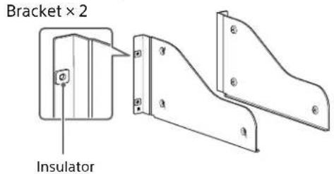
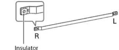
Mounting the receiver using the rack mount kit
Make sure to use a "WS-RE1" dedicated rack mount kit for this receiver when mounting the receiver on a rack mount.
1 Check that all parts are included.
Blank panel × 1

M5 screw × 6

Washer × 6
2 Remove screws from the right side of the receiver. Do not remove screws other than those specified.
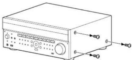
3 Mount the bracket on the right side of the receiver in the order of the step numbers printed on the bracket using the screws removed in step 2.
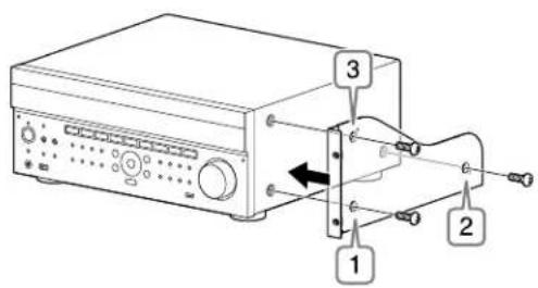
4 Repeat steps 2 and 3 for the left side to mount the bracket.
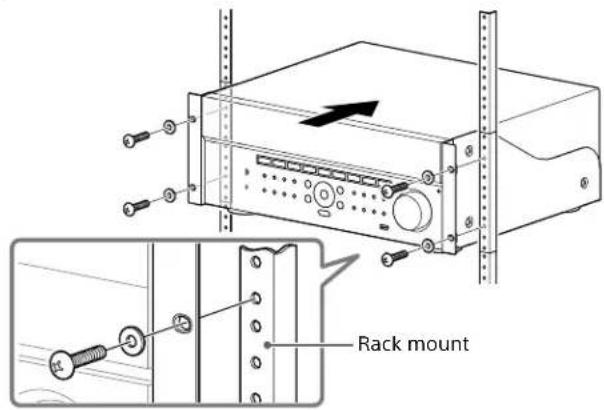
5 Mount the receiver to the rack system. Make sure to perform this step with more than one person.
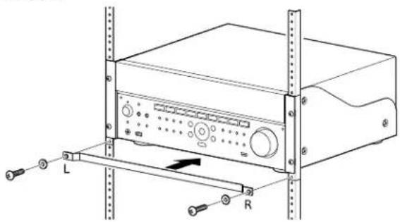
6 Mount the blank panel. (The blank panel hides the legs of the receiver to give it a cleaner look. Aligning the height of the receiver and blank panel lets it fit into a 4U size space.)
Zone distribution
The receiver can deliver input signals for each video or audio input to another zone in combinations such as the following.
Zone distribution capability (video)
| Video Input Main Zone | HDMI A OUT | HDMI OUT B Main Zone | MONITOR OUT (Composite) | Main Zone MONITOR OUT (Component) | Zone 2 MONITOR OUT (Composite) | |
| Main Zone HDMI B OUT | Zone 2 HDMI OUT | |||||
| VIDEO input jacks (composite) | ✓ ✓ ✓ *1 ✓ -✓ | |||||
| VIDEO input jacks (component) | ✓ ✓ ✓ *1 -✓ - | |||||
| HDMI IN jacks | ✓ ✓ ✓ -*2 -*2 -*2 | |||||
1 The receiver cannot output a different analog signal to the zone 2 HDMI OUT jack while an analog signal of the main zone is being output from the HDMI OUT A jack.
2 HDMI down converting is prohibited by HDMI guidelines.
Zone distribution capability (audio)
| Input Source / Output | Main Zone HDMI A OUT | HDMI OUT B Main Zone | SPEAKER OUT | Zone 2 SPEAKER OUT | Zone 2 PRE OUT (Fixed/Variable) | Zone 3 PRE OUT (Fixed/Variable) | Multi Ch PRE-OUT (ZA3000ES Only) | ||
| Main Zone HDMI B OUT | Zone 2 HDMI OUT | ||||||||
| Audio input jacks (RCA) | --✓✓✓✓✓*3✓ | ||||||||
| Built-in Tuner | --✓✓✓✓✓✓✓ | ||||||||
| DIGITAL OPTICAL IN jacks | - | - | ✓*1 | ✓ | ✓*1 | ✓*1 | ✓*1 | - | ✓ |
| DIGITAL COAXIAL IN jack | - | - | ✓*1 | ✓ | ✓*1 | ✓*1 | ✓*1 | - | ✓ |
| HDMI IN jacks | ✓✓✓✓✓*2✓*2-✓ | ||||||||
- Digital audio stream is not supported for distributing signals such as Dolby Digital and DTS. The Digital Audio output setting should be "2ch PCM" on the player device.
2 Zone 2 speaker out and pre-out only support 2-channel audio output. Multi-channel stream signals are automatically converted to 2 channels signals. The DSD signal is not output to zone 2.
3 Only analog input can be selected in zone 3.
In-Ceiling Speaker mode
Sony has developed a new special sound mode for CI installation. This feature will virtually relocate the front and center in-ceiling speakers down to around the screen. That way, the customer will hear the actors' voices coming from the screen instead of the ceiling. This mode also makes music sound more natural in a room with in-ceiling speakers.
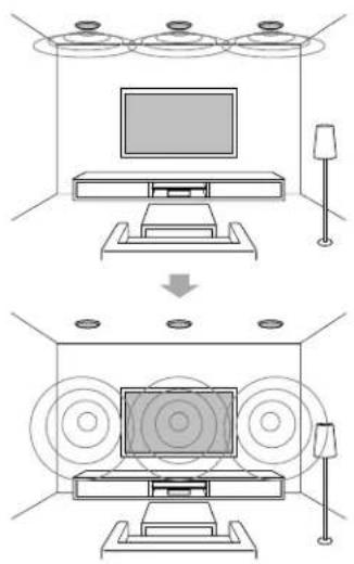
1 Perform Auto Calibration.
2 Select [Setup] - [Audio Setup] - [In-Ceiling Speaker Mode] - [On] from the home menu.
Notes
- This mode is not available when [Pro Logic II], [Pro Logic IIx], [Neo:6] or [2ch Analog Direct] is selected, or [Pure Direct] is set to [On].
- This mode will be disabled in a speaker pattern with front high speakers.
Tips
- You can select on/off for each input in Input Setup menu.
- You can also select [In-Ceiling Speaker Mode] in [Sound Effects] from the home menu.
- You can also switch the function on/off by pressing IN-CEILING SP on the remote control or the receiver.
- To obtain optimal effects in the listening environment, configure the [Ceiling Speaker Height] setting and perform Auto Calibration.
Preparation de I'ampli-tuner 7
https://us.en.kb.sony.com/app/answers/detail/a_id/44331--/how-to-use-the-4k-ultra-hdremote-app-for-sony-tablet.
https://www.4kactivation.com/
https://us.en.kb.sony.com/app/answers/detail/a_id/44331/~how-to-use-the-4k-ultra-hdremote-app-for-sony-tablet.
- Warning 41, Warning 42:
- Table of Contents
- Connections & settings (multi room/single room)
- Using the hidden commands
- Accessories
- Others
- Preparing the receiver
- Outline dimensional drawing
- Attaching/removing the front cover
- Setting up the receiver
- To activate the network standby mode
- To turn on the control mode to make an external controller connection
- Notes
- Connecting equipment
- Connecting a 4K TV that supports HDCP 2.2 to a 4K streaming box using a 4K-compatible HDMI cable
- If you are using an FMP-X10/X5 Media Player:
- Connect the receiver to a 4K media player using a High Speed HDMI cable (not supplied).
- Connect the receiver to your 4K TV using a High Speed HDMI cable (not supplied).
- If you are using an FMP-X1 Media Player:
- Connection pattern 1
- Important:
- "4K Ultra HD Remote" Android application for operating the FMP-X1
- Use the HDCP 2.2 compatible HDMI In jack of the 4K Bravia TV as noted below
- HDCP 2.2 compatible HDMI jacks of the receiver
- Connection pattern 2
- Connect the HDMI OUT 1 jack of your FMP-X1 with the HDCP 2.2 compatible HDMI IN jack of 4K Bravia TV.
- Connect the HDMI OUT 2 jack of your FMP-X1 with the HDMI IN jack of the receiver.
- Linking with a Hi-Fi music system
- To disable Music Connect
- Making a connection for PoE (Power over Ethernet) (for STR-ZA3000ES only)
- Making a multi-zone connection
- Sample setup
- Mixing separate audio/video inputs (Last video mode)
- Outputting a test tone from each speaker (Test Tone)
- Tips
- Displaying a test screen (Test Picture)
- Adjusting the sound balance automatically (Auto Calibration)
- Note
- Calibration Matching
- List of messages after Auto Calibration measurements
- Code 31:
- Code 32, Code 33:
- - Warning 40:
- - Warning 41, Warning 42:
- - Warning 43:
- - NO WARNING:
- Saving/ loading settings of the receiver
- To save the settings
- To load the settings
- Updating the firmware with a USB flash drive
- Setting up through a web browser
- Using the PING button
- Performing commands using the receiver
- Performing commands using the supplied remote control
- Turning on transmitting mode of the discrete code for the main zone
- While holding down MAIN, press INPUT MODE on the remote control for 5 seconds.
- To deactivate transmitting mode of the discrete code for the main zone
- Turning on transmitting mode of the discrete code for zone2/zone3
- Press ZONE2 or ZONE3 on the remote control when transmitting mode of the discrete code for the main zone is active.
- Mounting the receiver using the rack mount kit
- Check that all parts are included.
- Zone distribution
- In-Ceiling Speaker mode
Brand : SONY
Model : STRZA2000ES
Category : AV receiver