
MLE22PDAYW - Washing machine MAYTAG - Free user manual and instructions
Find the device manual for free MLE22PDAYW MAYTAG in PDF.

| Product Type | Commercial washing machine (washer) for use in laundromat |
| Power supply (washer) | 120 V, 60 Hz, 15 or 20 A, circuit protected by fuse or time-delay circuit breaker |
| Wash programs | Normal, Delicates, High Power Wash (PowerWash) |
| Temperature options | Cold, Warm, Hot |
| Maximum spin speed | 600, 750, 800 or 1000 rpm (adjustable) |
| Required water pressure | 20 to 100 psi (137.9 to 689.6 kPa) |
| Maximum total weight (water + load) | 204 kg (450 lb) |
| Tub material | Stainless steel (for most models) |
| Door lock function | Yes, during wash cycle |
| Drain system | Drain hose to sink, standpipe, or floor drain (min. height 762 mm, max. 2.4 m) |
| Regular maintenance | Monthly cleaning of the gasket/bellows with bleach solution, cleaning of dispenser drawer, replacement of water inlet hoses every 5 years |
| Internal cleaning cycle | Special cycle using 2/3 cup (160 ml) of liquid chlorine bleach |
| Lint filter (dryer) | Clean before or after each cycle (for combination models) |
| Gas safety | Gas odor detection, manual shut-off valve required, installation by qualified professional |
| Price adjustment | Programmable via the electronic control console: price per cycle, coin value, special schedules |
| Payment system compatibility | Coin (PD models) or debit card (PR models) with enhanced debit option |
| Limited warranty | 7 years for parts (labor not included); 5 years on major parts, 7 years on bearings, tub seal, drum, etc. |
| Available accessories | Drip tray (8212526), all-purpose cleaner (31682), storage rack (1903WH), drain kit (279818) |
| Tools needed for installation | Wrenches (8-10 inches), flat and Phillips screwdrivers, level, slip-joint pliers, utility knife, etc. |
Frequently Asked Questions - MLE22PDAYW MAYTAG
User questions about MLE22PDAYW MAYTAG
0 question about this device. Answer the ones you know or ask your own.
Ask a new question about this device
Download the instructions for your Washing machine in PDF format for free! Find your manual MLE22PDAYW - MAYTAG and take your electronic device back in hand. On this page are published all the documents necessary for the use of your device. MLE22PDAYW by MAYTAG.
USER MANUAL MLE22PDAYW MAYTAG
INSTALLATION INSTRUCTIONS
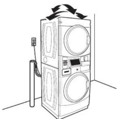
COMMERCIAL STACKED WASHER/ DRYER GAS OR ELECTRIC
INSTRUCTIONS D'INSTALLATION
LAVEUSE/SECHEUSE SUPERPOSEES
À USAGE COMMERCIAL
À GAZ OU ÉLECTRIQUE
Stacked Washer/Dryer Safety. 2
Tools & Parts 5
Alternate Parts and Accessories. 6
Dimensions/Clearances 7
Stacked Washer/Gas Dryer
Installation Requirements 8
Stacked Washer/Electric Dryer
Installation Requirements 11
Dryer Venting Requirements 15
Dryer Gas Supply Requirements 18
Installing Stacked Washer/Dryer.... 19
Washer Drain System 22
Electric Dryer Electrical
Connections 23
Leveling 27
Reversing Dryer Door Swing 29
Stacked Washer/Dryer
Maintenance Instructions 32
If You Need Assistance 33
Electronic Control Setup
Instructions 34
Warranty 40
TABLE DES MATIÈRES
Page
Dimensions/Distances
de dégagement 46
Your safety and the safety of others are very important.
We have provided many important safety messages in this manual and on your appliance. Always read and obey all safety messages.

This is the safety alert symbol.
This symbol alerts you to potential hazards that can kill or hurt you and others.
All safety messages will follow the safety alert symbol and either the word "DANGER" or "WARNING."
These words mean:
DANGER
You can be killed or seriously injured if you don't immediately follow instructions.
WARNING
You can be killed or seriously injured if you don't follow instructions.
All safety messages will tell you what the potential hazard is, tell you how to reduce the chance of injury, and tell you what can happen if the instructions are not followed.

WARNING - "Risk of Fire"
- Clothes dryer installation must be performed by a qualified installer.
- Install the clothes dryer according to the manufacturer's instructions and local codes.
- Do not install a clothes dryer with flexible plastic venting materials or flexible metal (foil type) duct. If flexible metal duct is installed, it must be of a specific type identified by the appliance manufacturer as suitable for use with clothes dryers. Flexible venting materials are known to collapse, be easily crushed, and trap lint. These conditions will obstruct clothes dryer airflow and increase the risk of fire.
- To reduce the risk of severe injury or death, follow all installation instructions.
- Save these instructions.
It is recommended that the owner post, in a prominent location, instructions for the customer's use in the event the customer smells gas. This information should be obtained from your gas supplier.
■Post the following warning in a prominent location.
FOR YOUR SAFETY
Do not store or use gasoline or other flammable vapors and liquids in the vicinity of this or any other appliance.

ARNING:
FIRE OR EXPLOSION HAZARD
Failure to follow safety warnings exactly could result in serious injury, death, or property damage.
-Do not store or use gasoline or other flammable vapors and liquids in the vicinity of this or any other appliance.
WHAT TO DO IF YOU SMELL GAS:
- Do not try to light any appliance.
- Do not touch any electrical switch; do not use any phone in your building.
- Clear the room, building, or area of all occupants.
- Immediately call your gas supplier from a neighbor's phone. Follow the gas supplier's instructions.
-
If you cannot reach your gas supplier, call the fire department.
-
Installation and service must be performed by a qualified installer, service agency, or the gas supplier.
WARNING: Gas leaks cannot always be detected by smell.
Gas suppliers recommend that you use a gas detector approved by UL or CSA.
For more information, contact your gas supplier.
If a gas leak is detected, follow the "What to do if you smell gas" instructions.
In the State of Massachusetts, the following installation instructions apply:
Installations and repairs must be performed by a qualified or licensed contractor, plumber, or gas fitter qualified or licensed by the State of Massachusetts.
Acceptable Shut-off Devices: Gas Cocks and Ball Valves installed for use shall be listed.
A flexible gas connector, when used, must not exceed 4 feet (121.9 cm).
IMPORTANT: The gas installation must conform with local codes, or in the absence of local codes, with the National Fuel Gas Code, ANSI Z223.1/NFPA 54, or the Natural Gas and Propane Installation Code, CSA B149.1.
The dryer must be electrically grounded in accordance with local codes, or in the absence of local codes, with the National Electrical Code, ANSI/NFPA 70, or the Canadian Electrical Code, Part 1, CSA C22.1.
IMPORTANT SAFETY INSTRUCTIONS
WARNING: To reduce the risk of fire, electric shock, or injury to persons when using the washer/dryer, follow basic precautions, including the following:
Read all instructions before using the washer/dryer.
- Do not place items exposed to cooking oils in your dryer. Items contaminated with cooking oils may contribute to a chemical reaction that could cause a load to catch fire.
- Do not wash or dry articles that have been previously cleaned in, washed in, soaked in, or spotted with gasoline, dry-cleaning solvents, other flammable, or explosive substances as they give off vapors that could ignite or explode.
- Do not add gasoline, dry-cleaning solvents, or other flammable, or explosive substances to the wash water. These substances give off vapors that could ignite or explode.
- Do not allow children to play on or in the washer/dryer. Close supervision of children is necessary when the washer/dryer is used near children.
Before the washer/dryer is removed from service or discarded, remove the doors to the washer/dryer compartments.
- Do not reach into the washer/dryer if the tub, agitator or drum is moving.
- Do not install or store the washer/dryer where it will be exposed to water and/or the weather.
Do not tamper with controls.
Clean dryer lint screen before or after each load.
Under certain conditions, hydrogen gas may be produced in a hot water system that has not been used for 2 weeks or more. HYDROGEN GAS IS EXPLOSIVE. If the hot water system has not been used for such a period, before using the washing machine, turn on all hot water faucets and let the water flow from each for several minutes. This will release any accumulated hydrogen gas. As the gas is flammable, do not smoke or use an open flame during this time.
- Do not repair or replace any part of the washer/dryer or attempt any servicing unless specifically recommended in this Use and Care Guide or in published user-repair instructions that you understand and have the skills to carry out.
- Do not use fabric softeners or products to eliminate static unless recommended by the manufacturer of the fabric softener or product.
- Do not use heat to dry articles containing foam rubber or similarly textured rubber-like materials.
- Keep area around the exhaust opening and adjacent surrounding areas free from the accumulation of lint, dust, and dirt.
The interior of the machine and dryer exhaust vent should be cleaned periodically by qualified service personnel.
See "Electrical Requirements" section of the Installation Instructions booklet for grounding instructions.
SAVE THESE INSTRUCTIONS
Tools Needed:
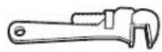
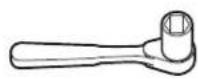
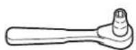
8" (203 mm) or 10" (254 mm) Pipe Wrench
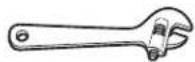
8^ (203 mm) or 10" (254 mm) Adjustable Wrench That Opens to 1^ (25 mm)
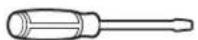
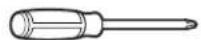
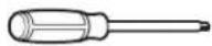
Flat-Blade Screwdriver Phillips Screwdriver
Torx T-20 Security Screwdriver or Bit
1" (25 mm) Hex-Head Socket Wrench
5/16" Socket Wrench
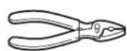
Pliers (that open to 1^8 / 16^ [39 mm])
Level
Utility Knife
1/4" (6 mm) Nut Driver
Locking Piers
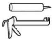
Caulk Gun and Caulk (for installing new exhaust vent)
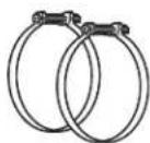
Vent Clamps
Pipe-Joint Compound Suitable for Gas Type
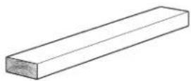
27^ (686 mm) Wood Block
Flashlight (optional)
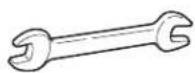
1/2" (13 mm) and 9/16" (14 mm) Open-End Wrenches
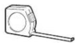
Ruler or Measuring Tape
Parts Supplied:
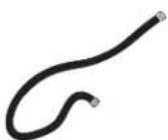
Water Inlet Hoses (2)

Inlet Hose Washers (4)
U-Shaped Hose Form
Transit Bolt Hole Plug (4)
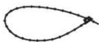
Beaded Tie Strap
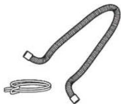
Drain Hose/Clamp
ALTERNATE PARTS AND ACCESSORIES
Alternate Parts
Your installation may require additional parts. If you are interested in purchasing one of the items listed here, call the toll-free number in the "If You Need Assistance" section.
If You Have: You Will Need to Buy:
| Overhead sewer Standard 20 gal. (76 L) 39" (990 mm) tall drain tub or utility sink, sump pump, and connectors (available from local plumbing suppliers) | |
| 1" (25 mm) standpipe | 2" (51 mm) diameter to 1" (25 mm) diameter Standpipe Adapter, Part Number 3363920 Connector Kit Part Number 285835 |
| Drain hose too short Extension Drain Hose, Part Number 285863 Connector Kit Part Number 285835 | |
| Lint clogged Drain Drain Protector, Part Number 367031 Connector Kit Part Number 285835 | |
| Floor drain system Siphon break, Part Number 285834 Connector Kit (x2) Part Number 285835 Extension Drain Hose, Part Number 285863 | |
| Water faucets beyond reach of fill hoses Two longer water fill hoses: 6 ft. (1.8 m) 90° bend hose, Part Number 76314 10 ft. (3.0 m), Part Number 350008 | |
Accessories
Enhance your washer/dryer with these premium accessories.
For more high-quality items or to order,
call 1-800-901-2042 or visit us at
www.maytag.com/accessories.
In Canada, call 1-800-807-6777 or visit us at
www.whirlpoolparts.ca
Part Number Accessory
| 8212526 Washer drip tray, fits under all | |
| 31682 All-purpose appliance cleaner | |
| 1903WH Laundry supply storage cart | |
| 279818 | 3-way dryer venting kit |
| 285834 | Siphon break kit |
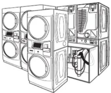
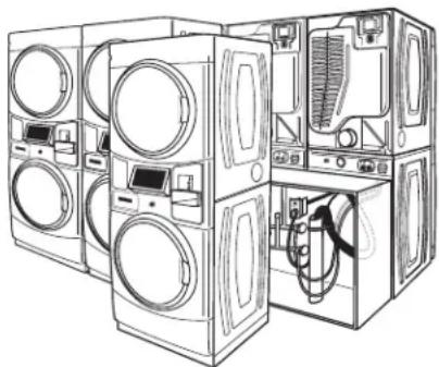
Front View Side View Back View
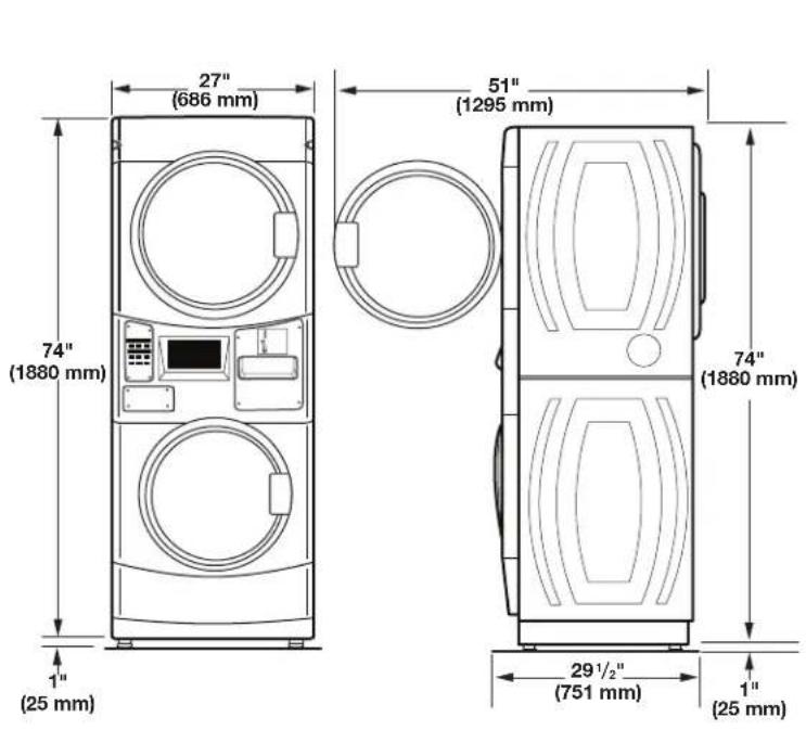
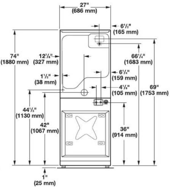
Clearances
Side Clearances Back/Top Clearances
STACKED WASHER/GAS DRYER INSTALLATION REQUIREMENTS
Stacked Washer/Gas Dryer Location
WARNING

Explosion Hazard
Keep flammable materials and vapors, such as gasoline, away from dryer.
Do not install in a garage.
Failure to do so can result in death, explosion, or fire.
Selecting the proper location for your washer/dryer improves performance and minimizes noise and possible washer "walk."
Your washer/dryer can be installed in a basement, laundry room, or recessed area. This washer/dryer is not intended for install in a mobile home or recreational vehicle. See the "Drain System" section for more information.
Companion appliance location requirements should also be considered.
IMPORTANT: Do not install or store the washer/dryer where it will be exposed to the weather. Do not store or operate the washer/dryer in temperatures at or below 32^ (0^) . Some water can remain in the washer and can cause damage in low temperatures. Proper installation is your responsibility.
You will need:
A water heater set to deliver 120^ (49^) water to the washer.
A grounded electrical outlet located within 6 ft. (1.8m) of where the power cord is attached to the back of the washer. See the "Electrical Requirements" section.
Hot and cold water faucets located within 4 ft. (1.2m) of the hot and cold water fill valves, and water pressure of 20-100 psi (137.9-689.6 kPa).
A level floor with a maximum slope of 1" (25 mm) under entire washer/dryer. Installing the washer/dryer on soft floor surfaces, such as carpets or surfaces with foam backing, is not recommended.
A sturdy and solid floor to support the washer/dryer with a total weight (water and load) of 450 lbs (204kg)
A floor drain under the bulkhead. Prefabricated bulkheads with electrical outlets, water inlet lines, and drain facilities should be used only where local codes permit.
Stacked washer/gas dryer installation clearances:
The location must be large enough to allow the washer and dryer doors to be fully opened.
Additional spacing should be considered for ease of installation and servicing. The doors open more than 180^ . The washer door is not reversible.
Additional clearances might be required for wall, door, and floor moldings.
Additional spacing of 1^ (25 mm) on all sides of the washer/ dryer is recommended to reduce noise transfer and to improve spin-up performance of the washer.
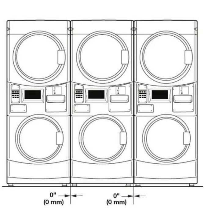
■Companion appliance spacing should also be considered.
When installing a gas dryer:
IMPORTANT: Observe all governing codes and ordinances.
Check code requirements: Some codes limit or do not permit installation of clothes dryers in garages, closets, or sleeping quarters. Contact your local building inspector.
Make sure that lower edges of the cabinet, plus the back and bottom sides of the washer, are free of obstructions to permit adequate clearance of air openings for combustion air. See the "Recessed Area and Closet Installation Instructions" below for minimum spacing requirements.
Recessed Area Installation Instructions
This washer/dryer may be installed in a recessed area. For recessed area installations, minimum clearances can be found on the warning label on the rear of the dryer or in the "Dimensions/Clearances" section.
The installation spacing is in inches and is the minimum allowable. Additional spacing should be considered for ease of installation, servicing, and compliance with local codes and ordinances.
NOTE: The dryer must be exhausted outdoors.
STACKED WASHER/GAS DRYER INSTALLATION REQUIREMENTS
Stacked Washer/Gas Dryer Electrical Requirements
WARNING

Electrical Shock Hazard
Plug into a grounded 3 prong outlet.
Do not remove ground prong.
Do not use an adapter.
Do not use an extension cord.
Failure to follow these instructions can result in death, fire, or electrical shock.
IMPORTANT: The washer/dryer must be electrically grounded in accordance with local codes and ordinances or, in the absence of local codes, with the National Electrical Code, ANSI/NFPA 70, latest edition, or Canadian Electrical Code, CSA C22.1. If codes permit and a separate ground wire is used, it is recommended that a qualified electrical installer determine that the ground path is adequate.
A copy of the above code standards can be obtained from:
National Fire Protection Association
One Batterymarch Park, Quincy, MA 02269
CSA International
8501 East Pleasant Valley Road
Cleveland, Ohio 44131-5575
Do not ground to a gas pipe.
Do not have a fuse in the neutral or ground circuit.
A 120 volt, 60Hz AC only, 15- or 20-amp, fused electrical circuit is required. A time-delay fuse or circuit breaker is also recommended. It is recommended that a separate circuit serving only this washer/dryer be provided.
This washer/dryer is equipped with a power supply cord having a 3 prong grounding plug.
To minimize the possibility of shock, the cord must be plugged into a mating, 3 prong, grounding-type outlet, grounded in accordance with local codes and ordinances. If a mating outlet is not available, it is the personal responsibility and obligation of the customer to have the properly grounded outlet installed by a qualified electrician.
If codes permit and a separate ground wire is used, it is recommended that a qualified electrician determine that the ground path is adequate.
Check with a qualified electrician if you are not sure the washer/dryer is properly grounded.
Stacked Washer/Gas Dryer Grounding
GROUNDING INSTRUCTIONS
For a grounded, cord-connected washer:
This washer must be grounded. In the event of a malfunction or breakdown, grounding will reduce the risk of electrical shock by providing a path of least resistance for electric current. This washer is equipped with a cord having an equipment-grounding conductor and a grounding plug.
The plug must be plugged into an appropriate outlet that is properly installed and grounded in accordance with all local codes and ordinances.
WARNING: Improper connection of the equipment-grounding conductor can result in a risk of electric shock. Check with a qualified electrician or serviceman if you are in doubt as to whether the appliance is properly grounded.
Do not modify the plug provided with the appliance - if it will not fit the outlet, have a proper outlet installed by a qualified electrician.
For a permanently connected washer:
This washer must be connected to a grounded metal, permanent wiring system, or an equipment grounding conductor must be run with the circuit conductors and connected to the equipment-grounding terminal or lead on the appliance.
GROUNDING INSTRUCTIONS
For a grounded, cord-connected dryer:
This dryer must be grounded. In the event of malfunction or breakdown, grounding will reduce the risk of electric shock by providing a path of least resistance for electric current. This dryer uses a cord having an equipment-grounding conductor and a grounding plug. The plug must be plugged into an appropriate outlet that is properly installed and grounded in accordance with all local codes and ordinances
For a permanently connected dryer:
This dryer must be connected to a grounded metal, permanent wiring system, or an equipment-grounding conductor must be run with the circuit conductors and connected to the equipment-grounding terminal or lead on the dryer.
WARNING: Improper connection of the equipment-grounding conductor can result in a risk of electric shock. Check with a qualified electrician or service representative or personnel if you are in doubt as to whether the dryer is properly grounded. Do not modify the plug on the power supply cord: if it will not fit the outlet, have a proper outlet installed by a qualified electrician.
SAVE THESE INSTRUCTIONS
STACKED WASHER/GAS DRYER INSTALLATION REQUIREMENTS
Stacked Washer/Gas Dryer Gas Supply
AWARNING

Explosion Hazard
Use a new CSA International approved gas supply line.
Install a shut-off valve.
Securely tighten all gas connections.
If connected to propane, have a qualified person make sure gas pressure does not exceed 13'' (33 cm) water column.
Examples of a qualified person include:
licensed heating personnel,
authorized gas company personnel, and authorized service personnel.
Failure to do so can result in death, explosion, or fire.
IMPORTANT: Observe all governing codes and ordinances.
This installation must conform with all local codes and ordinances.
In the absence of local codes, installation must conform with
American National Standard, National Fuel Gas Code ANSI
Z223.1/NFPA 54 or CAN/CSA B149.
A copy of the above code standards can be obtained from:
National Fire Protection Association
One Batterymarch Park, Quincy, MA 02269
CSA International
8501 East Pleasant Valley Road
Cleveland, Ohio 44131-5575
The design of this washer/dryer has been certified by CSA
International for use at altitudes up to 10,000 feet (3,048m) above sea level at the B.T.U. rating indicated on the model/serial plate.
Burner input adjustments are not required when the washer/dryer is operated up to this elevation.
When installed above 10,000 feet (3,048m) a four percent (4%)
reduction of the burner B.T.U. rating shown on the model/serial plate is required for each 1,000 foot (305m) increase in elevation.
For assistance when converting to other gas types and/or installing above 10,000 feet (3,048m) elevation, contact your local service company.
STACKED WASHER/ELECTRIC DRYER INSTALLATION REQUIREMENTS
Stacked Washer/Electric Dryer Location
WARNING

Explosion Hazard
Keep flammable materials and vapors, such as gasoline, away from dryer.
Do not install in a garage.
Failure to do so can result in death, explosion, or fire.
Selecting the proper location for your washer/dryer improves performance and minimizes noise and possible washer "walk."
Your washer/dryer can be installed in a basement, laundry room, or recessed area. This washer/dryer is not intended for install in a mobile home or recreational vehicle. See the "Drain System" section.
Companion appliance location requirements should also be considered.
IMPORTANT: Do not install or store the washer/dryer where it will be exposed to the weather. Do not store or operate the washer/dryer in temperatures at or below 32^ (0^) . Some water can remain in the washer and can cause damage in low temperatures. Proper installation is your responsibility.
You will need:
A water heater set to deliver 120^ (49^) water to the washer.
A grounded electrical outlet located within 6 ft. (1.8m) of where the power cord is attached to the back of the washer. See "Electrical Requirements."
Hot and cold water faucets located within 4 ft. (1.2 m) of the hot and cold water fill valves, and water pressure of 20-100 psi (137.9-689.6 kPa).
A level floor with a maximum slope of 1" (25 mm) under entire washer/dryer. Installing the washer/dryer on soft floor surfaces, such as carpets or surfaces with foam backing, is not recommended.
A sturdy and solid floor to support the washer/dryer with a total weight (water and load) of 450 lbs (204kg)
A floor drain under the bulkhead. Prefabricated bulkheads with electrical outlets, water inlet lines, and drain facilities should be used only where local codes permit.
Stacked washer/electric dryer installation clearances
The location must be large enough to allow the washer and dryer doors to be fully opened.
Additional spacing should be considered for ease of installation and servicing. The doors open more than 180^ . The washer door is not reversible.
Additional clearances might be required for wall, door, and floor moldings.
Additional spacing of 1^ (25 mm) on all sides of the washer/ dryer is recommended to reduce noise transfer, and improve spin-up performance of washer.
■Companion appliance spacing should also be considered.
Recessed Area and Closet Installation Instructions
This washer/dryer may be installed in a recessed area or closet. For recessed area and closet installations, minimum clearances can be found on the warning label on the rear of the dryer.
The installation spacing is in inches and is the minimum allowable. Additional spacing should be considered for ease of installation, servicing, and compliance with local codes and ordinances.
NOTE: The dryer must be exhausted outdoors.
STACKED WASHER/ELECTRIC DRYER INSTALLATION REQUIREMENTS
Stacked Washer/Electric Dryer Electrical Requirements
Washer Electrical Requirements
WARNING

Electrical Shock Hazard
Plug into a grounded 3 prong outlet.
Do not remove ground prong.
Do not use an adapter.
Do not use an extension cord.
Failure to follow these instructions can result in death, fire, or electrical shock.
■Do not have a fuse in the neutral or ground circuit.
This washer/dryer is equipped with a power supply cord having a 3 prong grounding plug.
To minimize the possibility of shock, the cord must be plugged into a mating, 3 prong, grounding-type outlet, grounded in accordance with local codes and ordinances. If a mating outlet is not available, it is the personal responsibility and obligation of the customer to have the properly grounded outlet installed by a qualified electrician.
If codes permit and a separate ground wire is used, it is recommended that a qualified electrician determine that the ground path is adequate.
Check with a qualified electrician if you are not sure the washer is properly grounded.
Stacked Washer/Electric Dryer Grounding
GROUNDING INSTRUCTIONS
For a grounded, cord-connected washer:
This washer must be grounded. In the event of a malfunction or breakdown, grounding will reduce the risk of electrical shock by providing a path of least resistance for electric current. This washer is equipped with a cord having an equipment-grounding conductor and a grounding plug. The plug must be plugged into an appropriate outlet that is properly installed and grounded in accordance with all local codes and ordinances.
WARNING: Improper connection of the equipment-grounding conductor can result in a risk of electric shock. Check with a qualified electrician or serviceman if you are in doubt as to whether the appliance is properly grounded.
Do not modify the plug provided with the appliance - if it will not fit the outlet, have a proper outlet installed by a qualified electrician.
For a permanently connected washer:
This washer must be connected to a grounded metal, permanent wiring system, or an equipment grounding conductor must be run with the circuit conductors and connected to the equipment-grounding terminal or lead on the appliance.
GROUNDING INSTRUCTIONS
For a grounded, cord-connected dryer:
This dryer must be grounded. In the event of malfunction or breakdown, grounding will reduce the risk of electric shock by providing a path of least resistance for electric current. This dryer uses a cord having an equipment-grounding conductor and a grounding plug. The plug must be plugged into an appropriate outlet that is properly installed and grounded in accordance with all local codes and ordinances.
For a permanently connected dryer:
This dryer must be connected to a grounded metal, permanent wiring system, or an equipment-grounding conductor must be run with the circuit conductors and connected to the equipment-grounding terminal or lead on the dryer.
WARNING: Improper connection of the equipment-grounding conductor can result in a risk of electric shock. Check with a qualified electrician or service representative or personnel if you are in doubt as to whether the dryer is properly grounded. Do not modify the plug on the power supply cord: if it will not fit the outlet, have a proper outlet installed by a qualified electrician.
SAVE THESE INSTRUCTIONS
STACKED WASHER/ELECTRIC DRYER INSTALLATION REQUIREMENTS
Dryer Electrical Requirements
It is your responsibility:
To contact a qualified electrical installer.
To be sure that the electrical connection is adequate and in conformance with the National Electrical Code, ANSI/NFPA 70-latest edition and all local codes and ordinances.
The National Electrical Code requires a 4-wire power supply connection for homes built after 1996, dryer circuits involved in remodeling after 1996, and all mobile home installations.
A copy of the above code standards can be obtained from: National Fire Protection Association, One Batterymarch Park, Quincy, MA 02269.
To supply the required 3- or 4-wire, single phase, 240 volt, 60Hz AC only electrical supply (or 3 or 4 wire, 120/208 volt electrical supply, if specified on the serial/rating plate) on a separate 30 amp circuit, fused on both sides of the line. A time delay fuse or circuit breaker is recommended. Connect to an individual branch circuit. Do not have a fuse in the neutral or grounding circuit.
Do not use an extension cord.
If codes permit and a separate ground wire is used, it is recommended that a qualified electrician determine that the ground path is adequate.
Electrical Connection
To properly install your dryer, you must determine the type of electrical connection you will be using and follow the instructions provided for it here.
This dryer is manufactured ready to install with a 3-wire electrical supply connection. The neutral ground conductor is permanently connected to the neutral conductor (white wire) within the dryer. If the dryer is installed with a 4-wire electrical supply connection, the neutral ground conductor must be removed from the external ground connector (green screw), and secured under the neutral terminal (center or white wire) of the terminal block. When the neutral ground conductor is secured under the neutral terminal (center or white wire) of the terminal block, the dryer cabinet is isolated from the neutral conductor.
If local codes do not permit the connection of a neutral ground wire to the neutral wire, see the "Optional 3-wire connection" section.
A 4-wire power supply connection must be used when the appliance is installed in a location where grounding through the neutral conductor is prohibited. Grounding through the neutral is prohibited for (1) new branch-circuit installations, (2) mobile homes, (3) recreational vehicles, and (4) areas where local codes prohibit grounding through the neutral conductor.
Electric Dryer Power Supply Cord
WARNING

Fire Hazard
Use a new UL listed 30 amp power supply cord.
Use a UL listed strain relief.
Disconnect power before making electrical connections.
Connect neutral wire (white or center wire) to center terminal.
Ground wire (green or bare wire) must be connected to green ground connector.
Connect remaining 2 supply wires to remaining 2 terminals (gold).
Securely tighten all electrical connections.
Failure to do so can result in death, fire, or electrical shock.
If using a power supply cord:
Use a UL listed power supply cord kit marked for use with clothes dryers. The kit should contain:
A UL listed 30 amp power supply cord, rated 240 volt minimum. The cord should be type SRD or SRDT and be at least 4 ft. (1.22m) long. The wires that connect to the dryer must end in ring terminals or "U" shaped spade terminals with upturned ends.
A UL listed strain relief.
If your outlet looks like this:
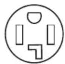
4-wire receptacle (14-30R)
Then choose a 4-wire power supply cord with ring or spade terminals and UL listed strain relief. The 4-wire power supply cord, at least 4 ft. (1.22m) long, must have four 10-gauge copper wires and match a 4-wire receptacle of NEMA Type 14-30R. The ground wire (ground conductor) may be either green or bare. The neutral conductor must be identified by a white cover.
If your outlet looks like this:

3-wire receptacle (10-30R)
Then choose a 3-wire power supply cord with ring or spade terminals and UL listed strain relief. The 3-wire power supply cord, at least 4 ft. (1.22 m) long, must have three 10-gauge copper wires and match a 3-wire receptacle of NEMA Type 10-30R.
STACKED WASHER/ELECTRIC DRYER INSTALLATION REQUIREMENTS
Dryer Direct Wire
WARNING

Fire Hazard
Use 10 gauge copper wire.
Use a UL listed strain relief.
Disconnect power before making electrical connections.
Connect neutral wire (white or center wire) to center terminal.
Ground wire (green or bare wire) must be connected to green ground connector.
Connect remaining 2 supply wires to remaining
2 terminals (gold).
Securely tighten all electrical connections.
Failure to do so can result in death, fire, or electrical shock.
If connecting by direct wire:
Power supply cable must match power supply (4-wire or 3-wire) and be:
Flexible armored cable or nonmetallic sheathed copper cable (with ground wire), covered with flexible metallic conduit. All current-carrying wires must be insulated.
10-gauge solid copper wire (do not use aluminum).
At least 5 ft. (1.52 m) long.
WARNING

Fire Hazard
Use a heavy metal vent.
Do not use a plastic vent.
Do not use a metal foil vent.
Failure to follow these instructions can result in death or fire.
WARNING: To reduce the risk of fire, this dryer must be exhausted outdoors.
IMPORTANT: Observe all governing codes and ordinances.
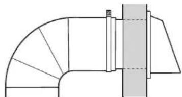
Dryer exhaust must not be connected into any gas vent, chimney, wall, ceiling, attic, crawlspace, or a concealed space of a building. Only rigid or flexible metal vent shall be used for exhausting.
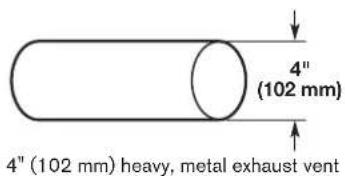
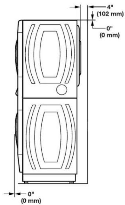
Only a 4^ (102 mm) heavy, metal exhaust vent and clamps may be used.
Do not use plastic or metal foil vent.
Rigid metal vent:
Recommended for best drying performance and to avoid crushing and kinking.
Flexible metal vent: (Acceptable only if accessible to clean)
Must be fully extended and supported in final dryer location.
Remove excess to avoid sagging and kinking that may result in reduced airflow and poor performance.
■Do not install in enclosed walls, ceilings, or floors.
The total length should not exceed 7 / 4 ft. (2.4m)
NOTE: If using an existing vent system, clean lint from entire length of the system and make sure exhaust hood is not plugged with lint. Replace plastic or metal foil vents with rigid metal or flexible metal vents. Review the "Vent System Chart" and if necessary, modify existing vent system to achieve best drying performance.
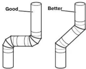
Elbows:
45^ elbows provide better airflow than 90^ elbows.
Clamps:
Use clamps to seal all joints.
Exhaust vent must not be connected or secured with screws or other fastening devices that extend into interior of duct and catch lint. Do not use duct tape.
Improper venting can cause moisture and lint to collect indoors, which may result in:
- Moisture damage to woodwork, furniture, paint, wallpaper, carpets, etc.
Housecleaning problems and health problems.
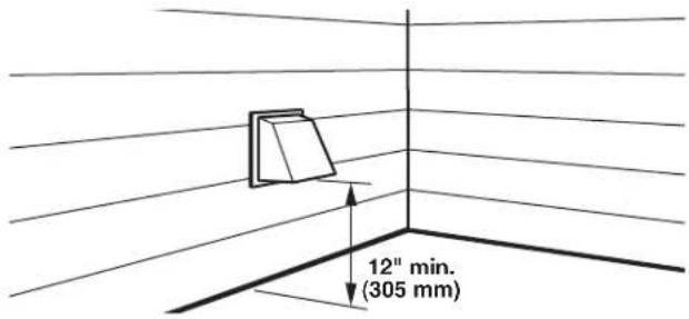
DRYER VENTING REQUIREMENTS
Vent Hoods
4^11(102mm) Diameter Exhaust Hoods
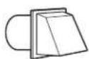

box hood louvered hood angled hood
Exhaust hood must be at least 12^ (305 mm) from the ground or any object that may be in the path of the exhaust (such as flowers, rocks, bushes, or snow).
Vent System Length
Maximum Vent Length/Vent Connection
Maximum length of vent system depends upon the type of vent used, number of elbows, and type of exhaust hood.
Vent System Chart (Rigid Metal Vent)
| No. of 90° Turns | Box and Louvered Hoods | Angled Hood |
| 0 135 ft. (41.2 m) | 129 ft. (39.3 m) | |
| 1 125 ft. (38.1 m) | 119 ft. (36.3 m) | |
| 2 115 ft. (35.1 m) | 109 ft. (33.2 m) | |
| 3 106 ft. (32.3 m) | 100 ft. (30.5 m) | |
| 4 98 ft. (29.9 m) | 92 ft. (28.0 m) |
For vent systems not covered by the vent specification chart, see your parts distributor.
Provision must be made for enough air for combustion and ventilation. (Check governing codes and ordinances.) See the "Recessed Area and Closet Installation Instructions" in the "Stacked Washer/Gas Dryer Location" and "Stacked Washer/ Electric Dryer Location" sections.
A 4^ (102 mm) outlet hood is preferred. However, a 212'' (64 mm) outlet exhaust hood may be used. A 212'' (64 mm) outlet creates greater back pressure than other hood types.
For permanent installation, a stationary vent system is required.
Connect Vent
- If connecting to existing vent, make sure the vent is clean.
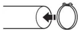
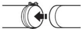
- Using a 4^ (102 mm) clamp, connect vent to exhaust outlet in dryer.
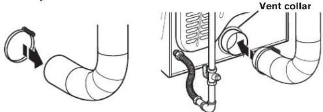
NOTE: Do not remove vent collar.
- Tighten hose clamp with Phillips screwdriver.
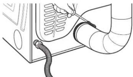
- Make sure the vent is secured to exhaust hood with a 4^ (102 mm) clamp.
- Move dryer into final position. Do not crush or kink vent. Make sure dryer is level.
If an Exhaust Hood Cannot be Used
The outside end of main vent should have a sweep elbow directed downward.
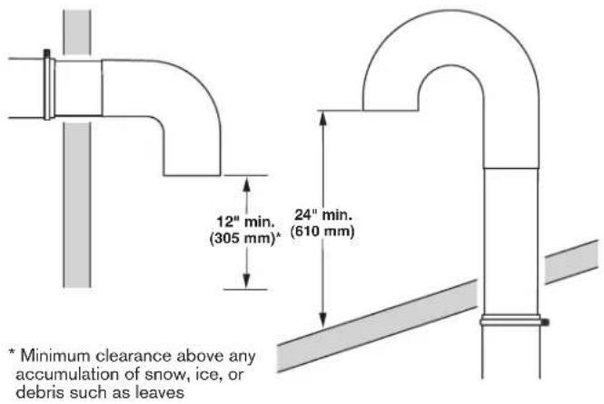
If main vent travels vertically through the roof, rather than through wall, install a 180^ sweep elbow on end of vent at least 2 ft. (610 mm) above surface of roof.
The opening in wall or roof shall have a diameter 1 / 2^ (13 mm) larger than vent diameter. Vent should be centered in opening.
Do not install screening over end of vent for best performance.
Multiple Dryer Venting
A main vent can be used for venting a group of dryers. The main vent should be sized to remove 200 CFM of air per dryer. Large-capacity lint screens of proper design may be used in main vent if checked and cleaned frequently. The room where the dryers are located should have make-up air equal to or greater than CFM of all the dryers in the room.
Back-draft Damper Kit, Part No. 3391910, is available from your distributor and should be installed in the vent of each dryer to keep exhausted air from returning into dryers and to keep exhaust in balance within main vent. Unobstructed return air openings are required.
Each vent should enter the main vent at an angle pointing in the direction of the airflow. Vents entering from the opposite side should be staggered to reduce the exhausted air from interfering with the other vents.
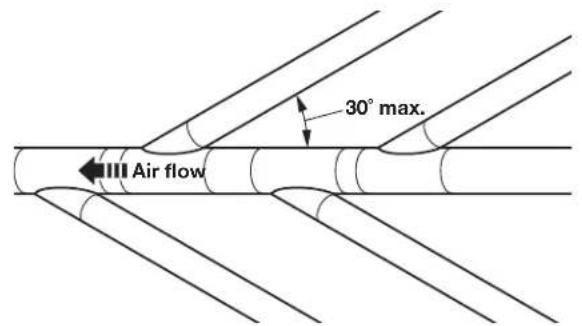
The maximum angle of each vent entering the main vent should be no more than 30^ .
DRYER GAS SUPPLY REQUIREMENTS
Type of Gas
This dryer is equipped for use with natural gas. It is design-certified by CSA International for propane and butane gases with appropriate conversion. No attempt shall be made to convert dryer from gas specified on serial/rating plate for use with a different gas without consulting the serving gas supplier.
Conversion must be done by a qualified service technician.
Gas conversion kit part numbers are listed on gas valve burner base.
Gas Supply Line
Recommended Method
Provide a gas supply line of 1 / 2^ (13 mm) rigid (IPS) pipe to dryer location. Pipe joint compounds that resist action of propane gas must be used. Do not use TEFLON* tape. With propage gas, piping or tubing size can be 1 / 2^ (13 mm) minimum. Usually, propane gas suppliers determine size and materials used in the system.
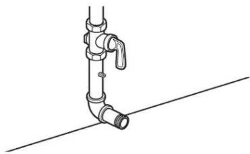
Gas Supply Pressure Testing
A 1/8'' (3 mm) NPT minimum plugged tapping, accessible for gauge testing, must be installed immediately downstream of the installed shut-off valve to the dryer (as shown above). The dryer must be disconnected from the gas supply piping system during any pressure testing of the system at test pressures in excess of 1/2'' psig (352kg/m^2) .
Alternate Method
The gas supply may also be connected using 3/8'' (10 mm) approved copper or aluminum tubing. If the total length of the supply line is more than 20 ft. (6.1 m), larger tubing will be required.
If using natural gas, do not use copper tubing. Pipe joint compounds that resist action of type of gas supplied must be used.
Shut-off valve required
The supply line must be equipped with a manual shut-off valve installed within 6 ft. (1.8 m) of dryer in accordance with National Fuel Gas Code, ANSI Z223.1. This valve should be located in same room as dryer. It should be in a location that allows ease of opening and closing. Do not block access to shut-off valve. In Canada, an individual manual shut-off valve must be installed in accordance with the B149 installation codes CAN/CGA B149.1 and CAN/CGA B149.2.
Flexible Metal Appliance Connector
It is recommended that a new flexible stainless steel gas line, design-certified by CSA International, be used for connecting the dryer to the gas supply line. (The gas pipe which extends through the lower rear of the dryer is provided with 38'' (10 mm) male pipe thread.)
NOTE: Do not kink or damage the flexible stainless steel gas line when moving the door.
Rigid Pipe Connection
The rigid pipe connection requires a combination of pipe fittings to obtain an in-line connection to dryer.
TEFLON is a registered trademark of Chemours.
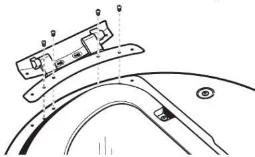
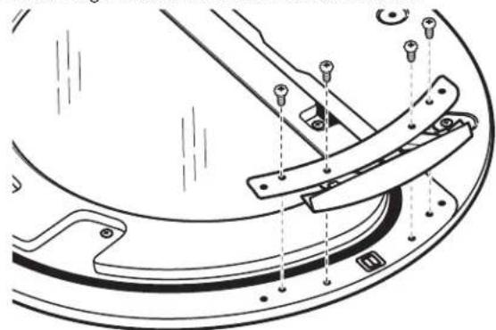
Remove Transport System
NOTE: Slide washer/dryer onto cardboard or hardboard before moving to avoid damaging floor covering.
WARNING
Excessive Weight Hazard
Use two or more people to move and install washer/dryer. Failure to do so can result in back or other injury.
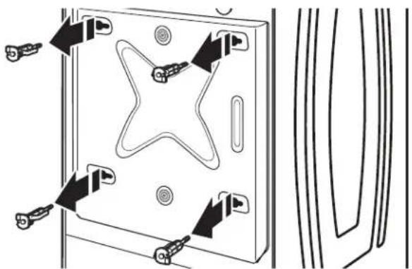
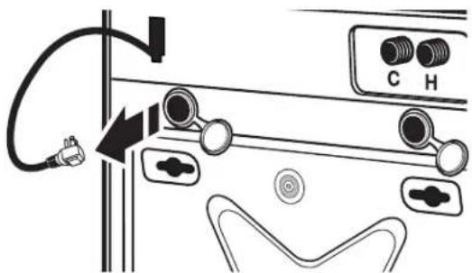
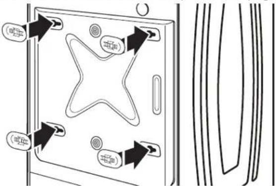
IMPORTANT: Position the washer/dryer so that the rear of the washer is within approximately 3 ft. (900 mm) of its final location. There are four shipping bolts in the rear panel of the washer that support the suspension system during transportation. These bolts also retain the power cord inside the washer until the bolts are removed.
- Keep the washer/dryer in the upright position while removing the shipping bolts.
- Using a 1/2'' (13 mm) wrench, loosen each of the bolts.
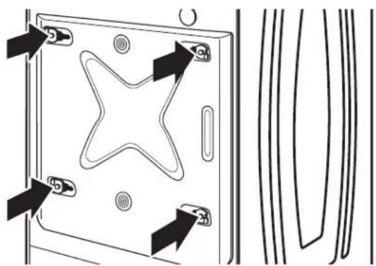
- Once the bolt is loose, move it to the center of the hole and completely pull out the bolt, including the plastic spacer covering the bolt. Once all four bolts are removed, discard the bolts and spacers.
- Models with separate washer power cords: Push the power cord plug into the opening on the right side of the rear panel and pull the power cord through the opening on the left side of the rear panel and close holes with the attached cap. Do not pull plug end of power cord through the right side hole.
NOTE: To avoid damage to internal washer parts or the power cord, if the cord does not pull out of the washer rear panel easily, do not force it. Remove the washer rear panel and guide the power cord around the obstruction and out the hole on the left side of the rear panel.
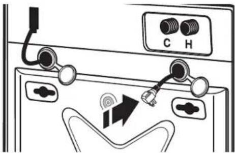
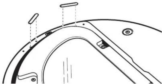
- Close the bolt holes with the four transport bolt hole plugs.
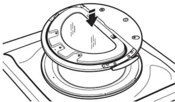
IMPORTANT: If the washer/dryer is to be transported, call your product distributor or installer. To avoid suspension and structural damage, your washer/dryer must be properly set up for relocation by a trained professional.
INSTALLING STACKED WASHER/DRYER
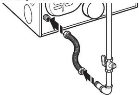
Connect Inlet Hoses
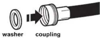
Insert new hose washers (supplied) into each end of the inlet hoses. Firmly seat the washers in the couplings.
Connect Inlet Hoses to Water Facets
Make sure the washer drum is empty.
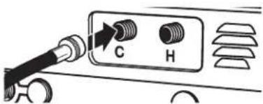
- Attach a hose to the hot water faucet. Screw on coupling by hand until it is seated on the washer.
- Attach a hose to the cold water faucet. Screw on coupling by hand until it is seated on the washer.
- Using pliers, tighten the couplings with an additional two-thirds turn.
NOTE: Do not overtighten or use tape or sealants on the valve. Damage to the valves can result.
Clear Water Lines
■Run water through both faucets and inlet hoses, into a laundry tub, drainpipe, or bucket, to get rid of particles in the water lines that might clog the inlet valve screens.
Check the temperature of the water to make sure that the hot water hose is connected to the hot water faucet and that the cold water hose is connected to the cold water faucet.
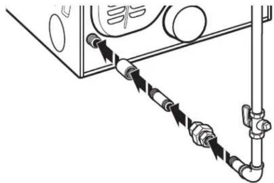
Connect Inlet Hoses to Washer
- Attach the cold water hose to the washer's cold water inlet valve. Screw on coupling by hand until it is seated on the washer.
- Attach the hot water hose to the washer's hot water inlet valve. Screw on coupling by hand until it is seated on the washer.
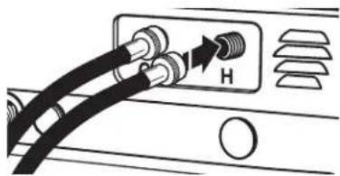
- Using pliers, tighten the couplings with an additional two-thirds turn.
NOTE: Do not overtighten. Damage to the valve can result.
- Turn on the water faucets completely and check for leaks.
NOTE: Replace inlet hoses after 5 years of use to reduce the risk of hose failure. Record hose installation or replacement dates on the hoses for future reference. Periodically inspect and replace hoses if bulges, kinks, cuts, wear, or leaks are found.
Route Drain Hose
Proper routing of the drain hose avoids damage to your floor due to water leakage. Read and follow these instructions.
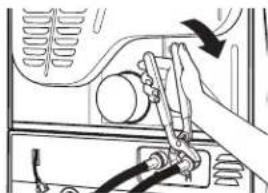
Remove drain hose from the washer drum
- Using locking pliers, squeeze hose clamp tabs together and insert over the end of the drain hose.
- Slide the drain hose onto the washer connection.
- Once the drain hose is in place, release the pliers.
- The washer drain system can be installed using a floor drain, wall standpipe, floor standpipe, or laundry tub.
Laundry tub drain or standpipe drain
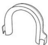
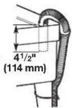
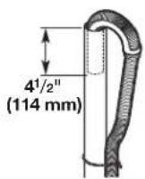
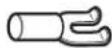
Connect the drain hose form to the corrugated drain hose.
Snap either end of the drain hose form to the drain hose at the point where the corrugation begins.
Bend drain hose over drain hose form and snap into place.
NOTE: Hose must not extend more than 1^ (25 mm) past the end of the U bend.
To keep drain water from going back into the washer:
- Do not straighten the drain hose, do not force excess drain hose into standpipe. Hose should be secure, but loose enough to provide a gap for air.
■Do not lay excess hose on the bottom of the laundry tub.
Floor drain
You may need additional parts. See the "Alternate Parts" section.
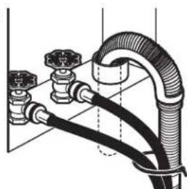
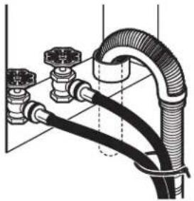
Secure Drain Hose
- Drape the power cord over the washer top.
- Move the washer to its final location.
- Place the drain hose in the laundry tub or standpipe, as shown.
- Secure the drain hose using the supplied beaded tie strap.
- If the washer faucets and the drain standpipe are recessed, put the hooked end of the drain hose in the standpipe as shown.
NOTES:
Do not force excess drain hose back into the rear of the washer.
To avoid siphoning, do not seal the drain hose into the standpipe.
The washer can be installed using the standpipe drain system (floor or wall), the laundry tub drain system, or the floor drain system.
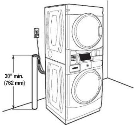
Standpipe drain system - wall or floor
The standpipe drain requires a minimum diameter standpipe of 2^ (50 mm). The minimum carry-away capacity can be no less than 10 gal. (38 L) per minute.
Wall
The top of the standpipe must be at least 30^ (762 mm) high and no higher than 96" (2.4 m) from the bottom of the washer.
Floor
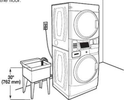
Laundry tub drain system
The laundry tub needs a minimum 20 gal. (76 L) capacity. The top of the laundry tub must be at least 30^ (762 mm) above the floor.
Floor drain system
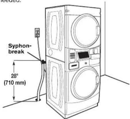
The floor drain system requires a siphon break that may be purchased separately.
The siphon break (Part Number 285834) must be a minimum of 28'' (710 mm) from the bottom of the washer. Additional hoses might be needed.
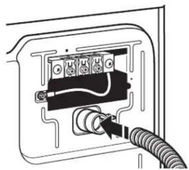
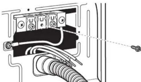
Strain Relief
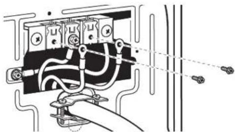
Remove Terminal Block Cover
Power Supply Cord Strain Relief
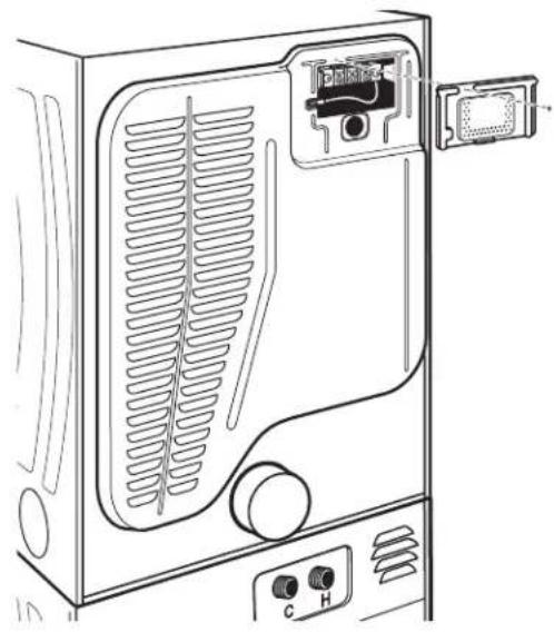
1. Insert strain relief.
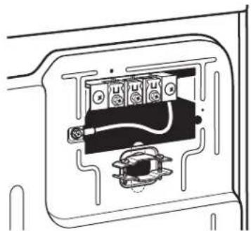
2. Insert power cord into strain relief.
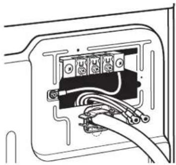
1. Insert strain relief.
Strain Relief (Direct Wire)
Direct Wire Strain Relief
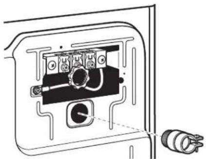
2. Insert conduit into strain relief and tighten clamp.
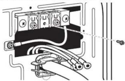
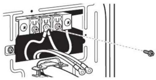
ELECTRIC DRYER ELECTRICAL CONNECTIONS
Connection Options
Power Cord
4-wire receptacle (NEMA Type 14-30R)

3-wire receptacle (NEMA Type 10-30R)

Direct Wire
4-wire direct
3-wire direct
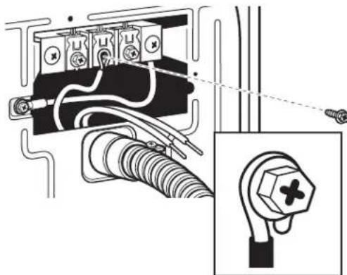
Connecting 4-Wire Connection: Power Supply Cord
IMPORTANT: A 4-wire connection is required for mobile homes and where local codes do not permit the use of 3-wire connections.
Standard Power Supply Cord Connectors
Flanged spade connector Ring Connector
Connecting Ground and Neutral Wires
- Remove center terminal block screw and the ground wire by removing the external ground connector screw.

- Connect ground and neutral wire to center terminal block.
Connecting Direct Wire Ground
- Connect ground wire (green or bare) with external ground connector screw.
Connecting Remaining Wires
- Connect remaining wires with outer terminal block screws.
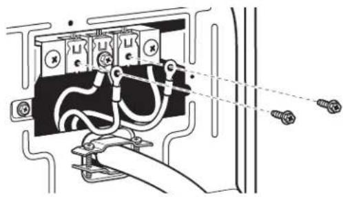
ELECTRIC DRYER ELECTRICAL CONNECTIONS
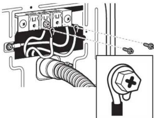
Connecting 3-Wire Connection: Power Supply Cord
Standard Power Cord Connectors
Flanged spade connector Ring Connector
Connecting Neutral Wire
- Loosen or remove center terminal block screw.
- Connect neutral wire to center terminal block.
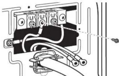
- Connect remaining wires with outer terminal block screws.
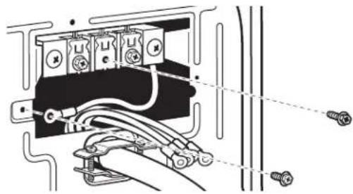
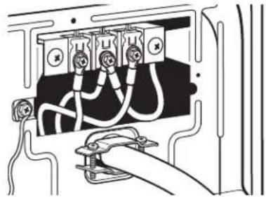
Connecting 4-Wire Connection: Direct Wire
IMPORTANT: A 4-wire connection is required for mobile homes and where local codes do not permit the use of 3-wire connections.
Direct wire cable must have 5 ft. (1.52 m) of extra length so dryer can be moved if needed.
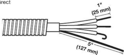
Strip 5" (127 mm) of outer covering from end of cable, leaving bare ground wire at 5" (127 mm). Cut 1^1/2 (38 mm) from three remaining wires. Strip insulation back 1" (25 mm). Shape ends of wires into a hook shape.
Connecting Ground and Neutral Wires
- Remove center terminal block screw and the ground wire by removing the external ground connector screw.
ELECTRIC DRYER ELECTRICAL CONNECTIONS
Connecting 4-Wire Connection: Direct Wire (cont.)
Connecting Ground and Neutral Wires (cont.)
- Connect ground and neutral wire to center terminal block.
Connecting Remaining Wires
- Connect remaining wires to outer terminal block.
Connecting Direct Wire Ground
- Connect ground wire (green or bare) with external ground connector screw.
Connecting 3-Wire Connection: Direct Wire
Use where local codes permit connecting cabinet-ground conductor to neutral wire.
Direct wire cable must have 5 ft. (1.52 m) of extra length so dryer can be moved if needed.
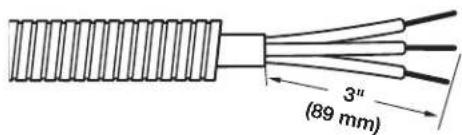
Strip 3^1/2 (89 mm) of outer covering from end of cable. Strip insulation back 1" (25 mm). If using 3-wire cable with ground wire, cut bare wire even with outer covering. Shape ends of wires into a hook shape.
Connecting Neutral Wire
- Loosen or remove center terminal block screw.
- Connect neutral wire to center terminal block.
- Connect remaining wires to outer terminal block.
ELECTRIC DRYER ELECTRICAL CONNECTIONS
Connecting 3-Wire Connection: Optional
Use for direct wire or power supply cord where local codes do not permit connecting cabinet-ground conductor to neutral wire.
Connecting Neutral Wire
- Remove center terminal block screw. Also remove neutral ground wire by removing external ground conductor screw.
- Connect neutral wire and neutral wire of power supply cord/ cable to center terminal block.
- Connect remaining wires to outer terminal block.
- Connect a separate copper ground wire from the external ground conductor to an adequate ground.
LEVELING
Leveling Stacked Washer/Dryer
Leveling your washer/dryer properly reduces excess noise and vibration.
WARNING
Excessive Weight Hazard
Use two or more people to move and install washer/dryer.
Failure to do so can result in back or other injury.
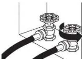
- Remove cardboard from beneath washer/dryer. Place a level on top edges of washer/dryer, checking each side and front. If not level, tip washer/dryer and adjust feet up or down as shown in Steps 3 and 4, repeating as necessary.

Not Level LEVEL Not Level
Leveling Stacked Washer/Dryer (cont.)
- Grip washer/dryer from top and rock back and forth, making sure all four feet are firmly on floor. Repeat, rocking washer/dryer from side to side. If washer/dryer rocks, go to Step 3 and adjust leveling feet. If all four feet are in firm contact with floor, go to Step 4.
- If washer/dryer is not level, use a 9/16'' or 14mm openend or adjustable wrench to turn jam nuts clockwise (as viewed from above) on feet until they are about 1/2'' (13 mm) from the washer/ dryer cabinet. Then turn the leveling foot counterclockwise to lower the washer/dryer or clockwise to raise the washer/dryer. Recheck levelness of washer/dryer and that all four feet are firmly in contact with the floor. Repeat as needed.
HELPFUL TIP: You may want to prop up front of washer/dryer about 4^ (102 mm) with a wood block or similar object that will support weight of washer/dryer.
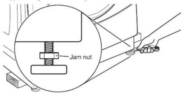
- When washer/dryer is level and all four feet are firmly in contact with the floor, use a 9/16" or 14 mm open-end or adjustable wrench to turn jam nuts counterclockwise (as viewed from above) on leveling feet tightly against washer/dryer cabinet.
HELPFUL TIP: You may want to prop washer/dryer with wooden block.
Complete Installation
- Check the electrical requirements. Be sure that you have the correct electrical supply and the recommended grounding method. See the "Electrical Requirements" section.
- Check that all parts are now installed. If there is an extra part, go back through the steps.
- Check that you have all of your tools.
- Dispose of/recycle all packaging materials.
- Check that the water faucets are on.
- Check for leaks around faucets and inlet hoses.
WARNING

Electrical Shock Hazard
Plug into a grounded 3 prong outlet.
Do not remove ground prong.
Do not use an adapter.
Do not use an extension cord.
Failure to follow these instructions can result in death, fire, or electrical shock.
- To test and to clean your washer, measure 1/2 the detergent manufacturer's recommended amount of High Efficiency (HE) detergent for a medium-size load. Pour the detergent into the detergent dispenser. Select any cycle and allow the washer to complete one whole cycle.
- Check dryer operation. Using a full heat cycle, let the dryer run for at least five minutes. Dryer will stop when time is used up.
NOTE: Dryer door must be closed for dryer to operate. When door is open, dryer stops, but timer continues to run. To restart dryer, close door and push cycle button.
If the burner does not ignite and you can feel no heat inside the dryer, shut off dryer for five minutes. Check that all supply valve controls are in "on" position and that the electrical cord is plugged in. Repeat five-minute test.
- Plug into a grounded outlet, or connect power.
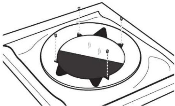
Remove the Door Assembly
- Place a towel or soft cloth on top of dryer or work space to avoid scratching of the surface.
- Remove three of the four screws that hold the door hinge on the front panel of the dryer. Partially loosen the remaining screw with keyhole opening and lift the door off the screw.
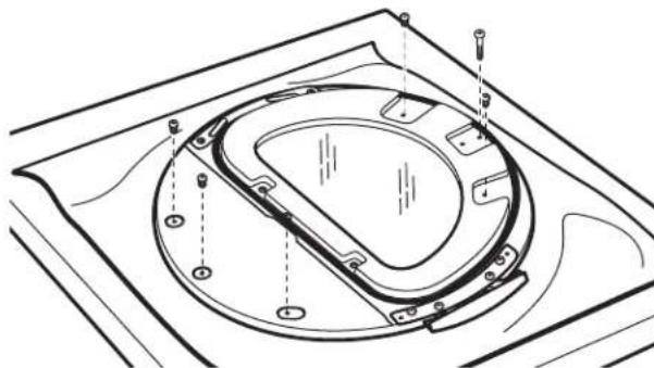
- Lay the door assembly on a previously prepared flat surface with the inside (inner door assembly) facing up, and remove six phillips-head screws to release outer door assembly from inner door assembly.
NOTE: It is important that you remove only the six indicated screws.
- Lift the inner door assembly off outer door assembly.
- Remove four Phillips-head screws to release center insert from outer door ring.
- Lift and rotate center insert 180 degrees.
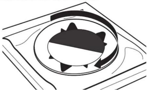
- Reassemble the center insert and outer door ring with the four screws
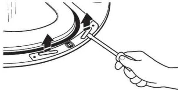
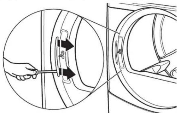
Reverse Hinge
- Use a small flat-blade screwdriver to remove two plug strips from the inner door. Slide the head of the screwdriver under the plugs, without scratching inner door surface, and lift up strip.
- Remove the four screws that attach to inner door hinge.
- Move hinge to other side. Reinstall four screws.
- Reinstall plug strips on opposite side of the inner door.
- Check for fingerprints on the glass. Clean if necessary.
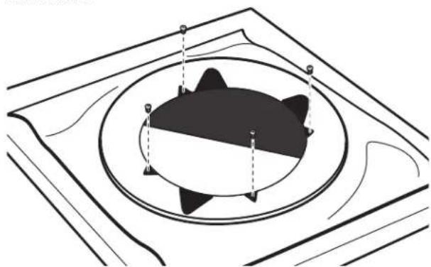
Replace the Door Assembly
- Place the inner door assembly inside the outer door assembly.
- Reassemble the inner and outer door assemblies with the six screws.
Reverse the strike
- Use a small flat-blade screwdriver to remove plug strip from the dryer door opening. Slide the head of the screwdriver under the plugs, without scratching dryer surface, and lift up strip.
- Remove the strike using a Phillips screwdriver.
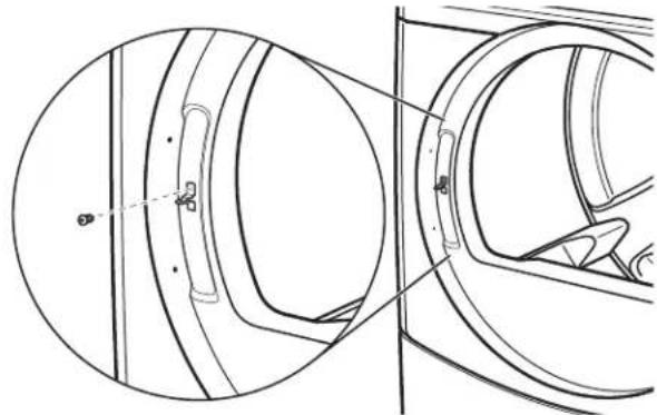
- Insert strike on the opposite side.
Reinstall the door
- Partially insert the third screw from the top; then slide the hinge onto this screw while hooking the hinge into the front panel hole. Reattach door to dryer front panel with the remaining three screws.
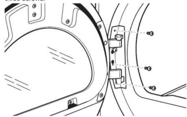
-
Check for fingerprints on the glass. Clean if necessary.
-
Close door and check that it latches securely.
Washer
Cleaning the Door Seal/Bellow
- Open the washer door and remove any clothing or items from the washer.
- Inspect inner glass door. If debris is present, wipe it off using a damp cloth.
- Inspect the colored seal/bellow between the door opening and the basket for stained areas. Pull back the seal/bellow to inspect all areas under the seal/bellow and to check for foreign objects.

Seal/bellow
- If stained areas are found, wipe down these areas of the seal/bellow:
a) Mix a dilute solution, using 3/4 cup (177 mL) of liquid chlorine bleach, and 1 gal. (3.8 L) of warm tap water.
b) Wipe the seal/bellow area with the dilute solution, using a damp cloth.
c) Let stand 5 minutes.
d) Wipe down area thoroughly with a dry cloth and let the washer interior air dry with door open.
IMPORTANT:
Wear rubber gloves when cleaning for prolonged periods.
Refer to the bleach manufacturer's instructions for proper use.
Maintenance Instructions:
This washer has a special cycle that uses higher water volumes in combination with liquid chlorine bleach to thoroughly clean the inside of the washer.
NOTES:
■Read these instructions completely before beginning the cleaning process.
If necessary, the cleaning cycle may be interrupted by pressing the Start button twice. However, this will not immediately stop the cycle. The washer will continue with several rinse and drain steps to ensure that all remaining bleach is rinsed from the washer.
To clean washer interior:
- Open the washer door and remove any clothing or items from the washer.
- Use liquid chlorine bleach: Open the dispenser drawer and immediately add 2/3 cup (160~mL) of liquid chlorine bleach to the bleach compartment.
NOTE: Do not add any detergent. Use of more than 2/3 cup (160~mL) of bleach will cause product damage over time.
- Close the washer door and the dispenser drawer.
- To start the Washer Cleanout cycle, first enter "Service Mode." Then press and hold the DELICATES button for 2 seconds. Press the EXTRA RINSE button until P-08 is displayed, then press the START button to start the cycle.
To exit out of the service mode and activate the clean wash cycle, push the DELICATES button, then turn the key.
NOTE: The door will lock, the basket will rotate 1/2 turn, then the door will unlock and lock again, then the Washer Cleanout Cycle will continue. The washer will not fill, but the basket will rotate while the washer runs a short sensing cycle. This will take approximately 3 minutes.
- The cycle will determine whether clothing or other items are in the washer.
a) If no items are detected in the washer, it will proceed to Step 7.
b) If any items are detected in the washer, "F-34" will be displayed. Then the door will unlock.
Enter the service mode and then press and hold the START button to cancel the failure code. Then repeat Steps 1, 3, and 4 to start the cycle again.
- Once the cycle has begun, allow the cycle to complete.
- After the cycle is complete, leave the door open slightly to allow for better ventilation and drying of washer interior.
STACKED WASHER/DRYER MAINTENANCE INSTRUCTIONS
Always do the following to maintain washer freshness:
■Use only HE (High Efficiency) detergent.
Leave the door slightly open after each cycle to allow for better ventilation and drying of washer interior.
Clean the washer monthly using the Washer Maintenance Procedure, using 2/3 cup (160 mL) of liquid chlorine bleach.
If the procedure does not sufficiently improve the washer freshness, please evaluate your installation and usage conditions for other causes.
Cleaning the exterior
Use a soft damp cloth or sponge to wipe up any spills.
Occasionally wipe the outside of your washer to keep it looking new. Use mild soap and water. Do not use abrasive products.
Cleaning the dispenser drawer
The dispenser drawer is removable for easy cleaning.
- Unlock the dispenser drawer for removal by inserting a flat-blade screwdriver into the catch release. Remove the dispenser drawer.
- Remove the inserts (the siphon from the softener and bleach compartments).
- Wash the parts under running water. NOTE: Do not wash components in the dishwasher.
- Replace the inserts and return the dispenser to the drawer.
Water inlet hoses
Replace the inlet hoses after 5 years of use to reduce the risk of hose failure. Periodically inspect and replace inlet hoses if bulges, kinks, cuts, wear, or leaks are found.
When replacing your inlet hoses, record the date of replacement.
Dryer
Maintenance instructions:
Clean lint screen before and after each cycle.
Removing accumulated lint:
From inside the dryer cabinet:
Lint should be removed every 2 years or more often, depending on dryer usage. Cleaning should be done by a qualified person.
From the exhaust vent:
Lint should be removed every 2 years, or more often, depending on dryer usage.
- Keep area around dryer clear and free from combustible materials, gasoline and other flammable vapors and liquids.
- Keep dryer area clear and free from items that would obstruct the flow of combustion and ventilation air.
If dryer does not operate, check the following:
Electrical supply is connected.
■Circuit breaker is not tripped or house fuse is not blown.
Door is closed. Listen closely to hear the door switch activate.
■Control is set up properly and display shows cycle time.
■Cycle selection button has been pushed firmly.
For gas dryers, check that gas supply shut-off valves are set in open position.
IF YOU NEED ASSISTANCE
Contact your authorized Maytag® Commercial Laundry distributor. To locate your authorized Maytag® Commercial Laundry distributor, or for web inquiries, visit www.MaytagCommercialLaundry.com.
You will need the washer/dryer model numbers and serial numbers. Both numbers can be found on the serial-rating plate located in the dryer door well.
Washer Control Dryer Control
General Washer/Dryer User Information
NOTE: After the washer/dryer has been installed and plugged in, the display will show "0 MINUTES" on the washer and dryer portions of the display. After the washer and dryer doors have been opened and closed, the display will show the price for each machine. On washer/dryers set for free cycles, the display sections will flash "SELECT CYCLE."
- PD Models: Insert coins until "SELECT CYCLE" flashes on the display portion of the washer or dryer that is to be run.
PR Models: A debit card is required rather than coins. Generation 1 or 2 debit card systems may be used; but when the Generation 2 debit system is used, the controls will automatically be set to Enhanced Debit mode (J. Ed). In Enhanced Debit mode, the card balance will also display when a debit card is inserted into the reader. - Door must be closed on the desired washer/dryer before cycle selection is made.
- Press the fabric setting button for the washer/dryer cycle desired. After the cycle is started, the time will display and count down.
- If a cycle is interrupted by opening the door or power loss, "RESELECT CYCLE" will flash in the display. To restart the washer/dryer, close door and reselect desired cycle.
NOTE: When set for free vend operation an ongoing dryer cycle will cancel if the door is opened.
Scrolling "OUT OF ORDER" Message, Followed by a Failure or Diagnostic Code Showing in Display
This condition indicates the washer/dryer is inoperative. Diagnostic codes being displayed on the upper portion of the display pertain to the dryer section, and diagnostic codes displayed on the lower portion of the display apply to the washer section. Diagnostic codes displayed on both the upper and lower portions of the display pertain to the control system of both the washer and dryer.
"0 MINUTES" Showing in Display
This indicates the cycle is complete and the washer/dryer cannot be operated. Coins dropped or debit inputs during this condition will be stored in escrow but cannot be used until normal operation is restored by opening and closing the door. If a door switch has failed, causing "0 MINUTES" to remain in the display after the door is opened and closed, it must be replaced before normal operation can be restored.
Cold Start (Initial first use)
Washer/dryer is programmed at the factory as follows:
Washer 11-minute wash period
$1.75 wash price (PD models)
$0.00 wash price (PR models)
3 rinses (extra rinse not enabled)
Dryer 5 minutes per quarter for PD models
45 minutes dry time for PR models
$1.50 dry price
(fixed cycle with top off - PD Models)
$0.00 dry price
(fixed cycle - PR Models)
ELECTRONIC CONTROL SETUP INSTRUCTIONS
Warm Start (after power failure)
A few seconds after power is restored, if a cycle was in progress at the time of the power failure, "RESELECT CYCLE" will flash in the display, indicating the need for a key press to restart washer or dryer.
Washer Door Lock
Prior to beginning a cycle, there is a door lock routine of lock/unlock/relock, then cycle begins. The door will remain locked until the end of a cycle or approximately 2 minutes after a power interruption.
Pricing
After the door is opened and then closed following the completion of a cycle, the display indicates the cycle price (unless set for free operation, where the display will flash "SELECT CYCLE"). As coins are dropped or debit inputs arrive, the display will change to lead the user through the initiation of a cycle.
There are four (4) types of dryer pricing:
Fixed "Vend" Pricing
A dryer setup for "Fixed Cycle" operation can only accept additional time accumulated by increments equal to the length of a complete dry cycle. A maximum of 99 minutes may be purchased; no additional credit is given for coins dropped with 99 minutes in the display.
Accumulator Pricing
If the price is set to one Coin 1, then accumulator pricing is in effect. Cycle time can be purchased one coin at a time (PD models) up to the maximum time of 99 minutes.
Fixed Cycle With Top Off Pricing
A dryer set to offer "Top Off" capability will allow time to be added to an existing dry cycle in increments equal to the number of minutes of dry time per quarter (Coin 1), up to 99 minutes, regardless of the cost required to start the dryer. No credit is given for coins or debit inputs entered when the control is displaying 99 minutes.
PR Models: In Enhanced Debit Mode, the top off price can be set independently (see VALUE OF COIN 2), and the top off time is calculated according to the following equation:
top off time = x full cycle price full cycle price
Penny increment offset is not applied to top off purchases.
Free Cycles
This is established by setting the cycle price to zero. When this happens, "SELECT CYCLE" will appear rather than a cycle price. Any cycle started as a free cycle will automatically terminate when the door is opened.
Debit Card Ready
This washer/dryer is debit card ready. It will accept a variety of debit card systems, but does not come with a debit card reader. Refer to the debit card reader manufacturer for proper washer/ dryer setup. In models converted to a Generation 1 debit card system, debit pulses represent the equivalent of one coin (Coin 1).
Control Set-up Procedures
IMPORTANT: Read all instructions before operating.
PD/PR Models: Insert service switch key and turn counterclockwise.
PR Models: Once a Generation 2 debit card reader is installed (according to the reader manufacturer's instructions), the set-up modes can only be changed by inserting a set-up card (supplied by the reader manufacturer) into the card slot. Inserting the service switch key and turning will only allow access to the service mode.
The washer/dryer is now in the set-up mode. The lower fabric setting buttons and the lower portion of the display are used to set up the digital control for the washer. The upper three fabric setting buttons and the upper portion of the display are used to set up the controls for the dryer.
The display can contain four numbers and/or letters and a decimal point on both the top and bottom display portions. These are used to indicate the set-up codes and related code values available for use in programming the washer/dryer.
How to Use the Buttons to Program the Controls
Washer:
- POWER WASH—Upper left button is used to adjust the values associated with set-up codes. Pressing the button will increment the value. Rapid adjustment is possible by holding the button down.
- TEMPERATURE—Lower left button is used to adjust the values associated with set-up codes. Pressing the button will decrement the value. Rapid adjustment is possible by holding down the button.
- EXTRA RINSE—Lower middle button will advance through the set-up codes. Pressing the button will advance to the next available set-up code. Holding the button down will automatically advance through the set-up codes at a rate of 1 per second.
- DELICATES—the right button is used to select or deselect options.
Dryer:
- HEAVY DUTY—Left button is used to adjust the value associated with set-up codes. Pressing the button will increment the value. Rapid adjustment is possible by holding down the button.
- DELICATES—the right button is used to select or deselect options.
ELECTRONIC CONTROL SETUP INSTRUCTIONS
Start Operating Set-up
Washer/dryers are preset at the factory and do not require any programming. However, if you want to change the settings, follow the "Set-Up Codes" guide.
The code at the beginning of each segment is the factory default setting for the PD Models and is the same for the PR Models unless noted otherwise.
The set-up code is indicated by the one or two left-hand characters. The set-up code value is indicated by the two or three right-hand characters.
| Set-Up Codes | |
| Code Explanation | |
| 6 06 REGULAR | PRICE CYCLE (DRYER) |
| 6 06 Represents | the number of Coin 1s needed to start the dryer; may adjust from 0-200 (see b.05 set-up for value of quarters (Coin 1). Advance from 0-200 by pressing HEAVY DUTY. Factory default of 6 quarters = 1.50. |
| 6 00 PR Models | Only: Factory default of 6 00 or 0 quarters. |
| CYCLE VEND PRICE (WASHER) | |
| 6 07 NORMAL | NORMAL Regular Cycle Vend Price—Represents the number of Coin 1s needed to start the washer. Increase between 0 and 200 by pressing the POWERWASH button and decrease by pressing TEMPERATURE button. Factory preset for 7 coins =1.75. |
| 6 00 NORMAL | PR models only: Factory default of 6 00 or 0 quarters. |
| 6 07 DELICATE | DELICATES Regular Cycle Vend Price—Represents the number of Coin 1s needed to start the washer. Increase between 0 and 200 by pressing the POWERWASH button and decrease by pressing the TEMPERATURE button. Factory preset for 7 coins = 1.75. |
| 6 00 DELICATE | PR models only: Factory default of 6 00 or 0 quarters. |
| 6 07 POWERWASH | POWERWASH Regular Cycle Vend Price—Represents the number of Coin 1s needed to start the washer. Increase between 0 and 200 by pressing the POWERWASH button and decrease by pressing the TEMPERATURE button. Factory preset for 7 coins =1.75. |
| 6 00 POWERWASH | PR models only: Factory default of 6 00 or 0 quarters. Press the EXTRA RINSE button once to advance to next code. |
| 7 05 REGULAR | DRY TIME (DRYER) |
| 7 05 | PD Models: Represents the number of minutes per quarter (Coin 1). Factory default of 5 minutes per coin. Example: 6 quarters x 5 minutes = 30 minutes. By pressing the HEAVY DUTY button, value adjusts from 1-99 minutes. |
| 7 45 PR Models | Represents the cycle length for free cycles. Example: "7 45" = 45 minutes. |
| 7 11 WASH LENGTH (WASHER) | |
| 7 11 This is the n | number of minutes for wash. Washer comes from the factory preset with 11 minutes. Choose from 9-17 minutes by pressing the POWERWASH button and decrease by pressing the TEMPERATURE button. Press the EXTRA RINSE button once to advance to next code. |
| 8 00 TYPE OF DRYER PRICING (DRYER) | |
| 8 00 Fixed cycle | with top off. For detailed description, see General User Information. |
| 8 FC | PR models only: Factory default of FC. Fixed Cycle. For detailed description, see General User Information.Use DELICATES button to make this selection. |
| 8 00 ADDITIONAL | AL RINSE OPTION/EXIT SERVICE MODE (WASHER)Note: this only affects NORMAL and DELICATES cycles. Additional Rinse is always enabled for POWERWASH. |
| 8 00 Additional R | Rinse not selected Off.Use this field to exit Service Mode when entered via the key dance. Press and hold the TEMPERATURE button to exit Service Mode. |
| 8 AR Additional | Rinse selected, On.Press the DELICATES button to change settings between 00 and AR.Use this field to exit Service Mode when entered via the key dance. Press and hold the TEMPERATURE button to exit Service Mode.Press the EXTRA RINSE button once to advance to next code. |
| 9 00 CYCLE CO | UNTER OPTION (WASHER)This option is either selected On or not selected Off. |
| 9 00 Not selected | Off |
| 9 0C Selected On | n and not able to be deselcted.Press DELICATES button three consecutive times to select On. Once On is selected, it cannot be delectd.Press the EXTRA RINSE button once to advance to next code. |
| 1.00 MONEY CO | UNTER OPTION (WASHER)This option is either selected On or not selected Off |
| 1.00 Not selected | Off |
| 1.0C Selected On | Press DELICATES button three consecutive times to select On and three consecutive times to remove (not selected Off). Counter resets by going from Off to On. |
| 1.C0 Selected On | n and not able to be deselected.To select On and not able to be deselected, first select On, then within two seconds press DELICATES twice, POWERWASH once, and exit the set-up mode.Press the EXTRA RINSE button once to advance to next code. |
| 2.00 SPECIAL | PRICING OPTION (WASHER)This option is either selected on or not selected Off. |
| 2.00 Not selected | off. |
| 2.SP Selected on | n. Press the DELICATES button once for this selection. |
| If special pricing option is selected, you have access to codes "3." through "9."NOTE: An external battery needs to be added to keep the clock running during periods of power outages.Press the EXTRA RINSE button once to advance to next code. | |
ELECTRONIC CONTROL SETUP INSTRUCTIONS
| OPTIONS TO USE IF SPECIAL PRICING IS SELECTED (DRYER): | |
| SPECIAL CYCLE PRICE (DRYER) | |
| 3 06 Represents | the number of quarters (Coin 1) needed to start the dryer, may adjust from 0-200. (See b.05 set-up for value of Coin 1). Advance from 0-200 by pressing HEAVY DUTY. Factory default of 6 quarters = 1.50. |
| 3.00 PR Models: | Factory default of 0 quarters. |
| OPTIONS TO USE IF SPECIAL PRICING IS SELECTED (WASHER): | |
| 3.07 NORMAL | NORMAL Special Cycle Vend Price—Increase between 0 and 200 by pressing the POWERWASH button and decrease by pressing the TEMPERATURE button. Factory preset for 7 coins =1.75. |
| 3 00 NORMAL | PR models only: Factory default of 6 00 or 0 quarters. |
| 3.07 DELICATES | DELICATES Special Cycle Vend Price—Increase between 0 and 200 by pressing the POWERWASH button and decrease by pressing the TEMPERATURE button. Factory preset for 7 coins = 1.75. |
| 3 00 DELICATES | PR models only: Factory default of 6 00 or 0 quarters. |
| 3.07 POWERWASH | POWERWASH Regular Cycle Vend Price—Increase between 0 and 200 by pressing the POWERWASH button and decrease by pressing the TEMPERATURE button. Factory preset for 7 coins =1.75. |
| 3 00 POWERWASH | PR models only: Factory default of 6 00 or 0 quarters. Press the EXTRA RINSE button once to advance to the next code. |
| 4.05 SPECIAL DRY TIME (DRYER) | |
| 4.05 | PD Models: Represents the number of minutes per quarter (Coin 1). Factory default of 5 minutes per coin. Example: 6 quarter x 5 minutes = 30 minutes. By pressing the HEAVY DUTY button, the value can be adjusted from 1-99 minutes. |
| 4.45 PR Models: | Represents the fixed cycle time in minutes. Example: "4.45" = 45 minutes. Press the EXTRA RINSE button once to advance to next code. |
| 5.00 TIME-OF-DAY CLOCK, MINUTES (WASHER) | |
| 5.00 This is the T——→ | TIME-OF-DAY CLOCK, minute setting: select 0-59 minutes by pressing POWERWASH button. Press the EXTRA RINSE button once to advance to next code. |
| 6.00 TIME-OF-DAY CLOCK, HOURS (WASHER) NOTE: Uses military time—24 hr. clock. | |
| 6.00 This is the T——→ | TIME-OF-DAY CLOCK, hour setting: select 0-23 ours by pressing POWERWASH button. Press the EXTRA RINSE button once to advance to the next code. |
| 7.00 SPECIAL | PRICE START HOUR (WASHER) NOTE: Uses military time - 24 hr. clock |
| 7.00 This is the s | start hour; 0-23 hours. Select START HOUR by pressing POWERWASH button. Press the EXTRA RINSE button once to advance to the next code. |
| 8.00 SPECIAL | PRICE STOP HOUR (DRYER) NOTE: Uses military time - 24 hr. clock. |
| 8.00 This is the s | stop hour; 0-23 hours. Select STOP HOUR by pressing HEAVY DUTY button. Press the EXTRA RINSE button once to advance to the next code. |
| 9.10 SPECIAL | PRICE DAY (WASHER) |
| 9.10 This repre | nts the day of the week and whether special pricing is selected for that day. A number followed by "0" indicates no selection that particular day (9.1S). Day of the week (1-7) can be chosen by pressing the POWERWASH button. Press DELICATES button once to select special pricing for each day chosen. When exiting setup code "9.", the display must show current day of week: DISPLAY DAY OF THE WEEK CODE Selected) 10 Day 1 = Sunday 1S 20 Day 2 = Monday 2S 30 Day 3 = Tuesday 3S 40 Day 4 = Wednesday 4S 50 Day 5 = Thursday 5S 60 Day 6 = Friday 6S 70 Day 7 = Saturday 7S |
| → | Press the EXTRA RINSE button once to advance to next code. |
| A.00 | VAULT VIEWING OPTION (WASHER) This option is either selected On or not selected Off. |
| A.00 | Not selected Off. |
| A.5C | Selected On. Press DELICATES button once for this section. When selected, the money and/or cycle counts will be viewable (if counting is selected) when the coin box is removed. Press the EXTRA RINSE button once to advance to next code. |
| → | Press the EXTRA RINSE button once to advance to next code. |
| b.05 VALUE OF | COIN 1 (WASHER) |
| b.05 This repre | nts the value of Coin 1 in number of nickles. 05 = $0.25. Increase between 1 and 200 nickles by pressing the POWERWASH button and decrease by pressing the TEMPERATURE button. With coin drop activation, this represents the total vend price in nickles. Example: b.30 = $1.50. Press the EXTRA RINSE button once to advance to next code. |
ELECTRONIC CONTROL SETUP INSTRUCTIONS
| C.20 VALUE OF | COIN 2 (WASHER) |
| C.20 PD MODEL | S: This represents the value of coin 2 in number of nickles. 20 = $1.00. Increase between 1 and 200 nickles by pressing the POWERWASH button and decrease by pressing the TEMPERATURE button. |
| C.05 PR models | only: For models using Enhanced Debit, this field represents the value of top off in nickles, for the dryer, or $.25. Factory default of C.05; represents 5 x $.05, or $.25. Press the EXTRA RINSE button once to advance to next code. |
| E.00 ADD COINS | OPTION (WASHER) This option is either selected On or not selected Off. This option causes the customer display to show the number of coins (Coin 1) to enter, rather than the dollars-and-cents amount. |
| E.00 Not selected | Off. |
| E.AC Selected | On. Press DELICATES button three consecutive times for this selection. PR models only: In enhanced debits mode, this option is not selectable. Press the EXTRA RINSE button once to advance to next code. |
| Wash Upgrades (WASHER) | |
| H.00 COOL | COOL Temperature Upgrade Price-Set between 0 and 200 by pressing the POWERWASH (increase) button or pressing the TEMPERATURE (decrease) button. Factory preset for 0 coins = $0.00. |
| H.00 WARM | WARM Temperature Upgrade Price- Set between 0 and 200 by pressing the POWERWASH (increase) button or pressing the TEMPERATURE (decrease) button. Factory preset for 0 coins = $0.00. |
| H.00 HOT | HOT Temperature Upgrade Price-Set between 0 and 200 by pressing the POWERWASH (increase) button or pressing the TEMPERATURE (decrease) button. Factory preset for 0 coins = $0.00. |
| H.01 EXTRA RINSE | EXTRA RINSE Upgrade Price-Set between 0 and 200 by pressing the POWERWASH (increase) button or pressing the TEMPERATURE (decrease) button. Factory preset for 1 coins = $0.25. Press the EXTRA RINSE button once to advance to next code. |
| J.Cd COIN/DEE | OPTION (WASHER) |
| J.Cd Both coin a | debit selected. |
| J.d | Debit card selected, coins disabled. Press the DELICATES button three consecutive times for this selection. |
| J.C Coins select | , debit disabled. Press the DELICATES button three consecutive times for this selection. |
| J.Ed Enhanced | Debit is self-selected when a Generation 2 card reader is installed in the washer. The Ed option cannot be manually selected or deselected. Press the EXTRA RINSE button once to advance to next code. |
| L.00 PRICE SUPPRESSION OPTION(WASHER)This option causes the customer display to show "ADD" or "AVAILABLE" rather than the amount of money to add. (Used mainly in debit installations.) | |
| L.00 Not selected | Off |
| L.PS Selected Cn. Press the DELICATES button once for this selection.Press the EXTRA RINSE button once to advance to next code. | |
| n.CE CLEAR ES CROW OPTION (WASHER)When selected, money held in escrow for 30 minutes without further escrow or cycle activity will be cleared. | |
| n.CE Selected Cn. | |
| n.00 Not selected off. Press the DELICATES button once to deselect this selection.Press the EXTRA RINSE button once to advance to next code. | |
| r.800 TOP SPIN SPEED RPM (WASHER) | |
| r.800 This can be selected from the following spinspeeds: 600rpm, 750 rpm, 800 rpm, 1000 (displays as 999) rpm. Step between speeds by pressing the DELICATES button. Factory default of 800rpm.Press the EXTRA RINSE button once to advance to next code. | |
| U.00 PENNY INIncrement OFFSET (DRYER) | |
| U.00 This represents the penny increment price offset used in Generation 2 (Enhanced Debit) PR models. Choose from 0-4 pennies by pressing the HEAVY DUTY button. | |
| U.00 COIN (HUNDREDTH) INIncrement OFFSET(WASHER) | |
| U.00This represents the penny increments price offset used in Generation 2 (Enhanced Debit) PR models. Increase from 0-4 pennies by pressing the POWERWASH button decrease by pressing TEMPERATURE button.Press the EXTRA RINSE button once to advance to next code. | |
| CYCLE SETTINGS (WASHER) | |
| A1.03 PREWASH LENGTHThis is the number of minutes of PREWASH. Set bewtween 2 and 7 by pressing the POWERWASH (Increase) button or pressing the TEMPERATURE (decrease) button.Press the EXTRA RINSE button once to advance to next code. | |
| A2.03 FINAL SPIN LENGTHThis is the number of minutes of final high-speed spin. Set between 3 and 8 by pressing the POWERWASH (increase) button or pressing the TEMPERATURE (decrease) button.Press the EXTRA RINSE button once to advance to next code. | |
| A3.02 Normal Cycle Settings allows the owner to select the cycle default options of Water Temperature, Prewash, and Extra Rinse. See Table 1 for specific settings. Normal is set to 02 from the factory. Set by pressing the POWERWASH (increase) button or pressing the TEMPERATURE (decrease) button. | |
| → | Press the EXTRA RINSE button once to advance to next code. |
| A4.00 Delicates Cycle Settings allows the owner to select the cycle default options of Water Temperature, Prewash, and Extra Rinse. See Table 1 for specific settings. Delicates is set to 00 from the factory. Set by pressing POWERWASH (increase) button or pressing the TEMPERATURE (decrease) button. | |
| → | Press the EXTRA RINSE button once to advance to next code. |
| A5.0F Powerwash Cycle Settings allows the owner to select the cycle default options of Water Temperature, Prewash, and Extra Rinse. See Table 1 for specific settings. Powerwash is set to 0F from the factory. Set by pressing POWERWASH (increase) button or pressing the TEMPERATURE (decrease) button. | |
| → | Press the EXTRA RINSE button once to advance to next code. |
MAYTAG COMMERCIAL LAUNDRY LIMITED WARRANTY MHN33PDCWW, MHN33PDCXW, MHN33PDCGW, MHN33PRCWW, MHN33PNCGW
IF YOU NEED SERVICE:
Contact your authorized Maytag Commercial Laundry distributor. To locate your authorized Maytag Commercial Laundry distributor, visit www.MaytagCommercialLaundry.com.
For written correspondence:
Maytag Commercial Laundry Service Department
2000 N M 63
Benton Harbor, Michigan 49022-2632 USA
SEVEN YEAR LIMITED WARRANTY
WHAT IS COVERED
WHAT IS NOT COVERED
FIVE YEAR LIMITED WARRANTY (PARTS ONLY - LABOR NOT INCLUDED)
For the first five years from the original date of purchase, when this commercial appliance is installed, maintained, and operated according to the instructions attached to or furnished with the product, Maytag brand of Whirlpool Corporation (hereafter "Maytag") will pay for factory specified replacement parts to correct defects in materials or workmanship that existed when this commercial appliance was purchased. This limited warranty does not include labor.
SIXTH THROUGH SEVENTH YEAR LIMITED WARRANTY (CERTAIN COMPONENT PARTS ONLY - LABOR NOT INCLUDED)
In the sixth through seventh years from the date of original purchase, when this commercial appliance is installed, operated, and maintained in a vended and/or multi-housing environment ONLY according to instructions attached to or furnished with the product, Maytag will pay for factory specified replacement parts for the following components to correct non-cosmetic defects in materials or workmanship in the part that prevent functioning of the product and that existed when this commercial appliance was purchased. This is a limited 7-year warranty on the below named parts only and does not include labor.
Drive Bearings, Tub Seal, Bearing Spacer, Hub, Cross Piece, Drum, Rear Tub, Front Tub, Drum Shaft
YOUR SOLE AND EXCLUSIVE REMEDY UNDER THIS LIMITED WARRANTY SHALL BE PART REPLACEMENT AS PROVIDED HEREIN. Maytag recommends that you use an "authorized" service provider to diagnose and repair your Commercial Laundry product. Maytag will not be responsible under this warranty to provide additional replacement parts as a result of incorrect diagnosis or repair by an "unauthorized" service company. Except in the European Union, this limited warranty is valid only when the commercial appliance is used in the country in which it was purchased. This limited warranty is effective from the date of the original consumer purchase. Proof of original purchase date is required to obtain service under this limited warranty.
-
All other costs including labor, transportation, shipping, or custom duties for covered parts.
-
Factory specified replacement parts if this commercial appliance is used for other than normal, commercial use or when it is used in a manner that is inconsistent to published user or operator instructions and/or installation instructions.
-
Service calls to correct the installation of your commercial appliance, to instruct you on how to use your commercial appliance, to replace or repair house fuses, or to correct external wiring or plumbing.
-
Service calls to repair or replace appliance light bulbs, air filters, or water filters. Consumable parts are excluded from warranty coverage.
-
Damage resulting from improper handling of product during delivery, theft, accident, alteration, misuse, abuse, fire, flood, acts of God, improper installation, installation not in accordance with local electrical or plumbing codes, or use of products not approved by Maytag.
-
Pick up and delivery. This commercial appliance is designed to be repaired on location.
-
Repairs to parts or systems resulting from unauthorized modifications made to the commercial appliance.
-
The removal and reinstallation of your commercial appliance if it is installed in an inaccessible location or is not installed in accordance with published installation instructions.
-
Damage resulting from exposure to chemicals.
-
Changes to the building, room, or location needed in order to make the commercial appliance operate correctly.
-
Factory specified replacement parts on commercial appliances with original model/serial numbers that have been removed, altered, or cannot be easily determined.
-
Discoloration, rust, or oxidation of stainless steel surfaces.
-
Factory specified replacement parts as a result of incorrect diagnosis or repair by an "unauthorized" service company.
-
Replacement parts during the sixth through seventh years from the date of original purchase where the commercial appliance is installed, operated and maintained in a setting other than a vended and/or multi-housing environment.
-
Replacement parts during the sixth through seventh years from the date of original purchase where the defective part is not preventing the functioning of the product.
The cost of repair or replacement under these excluded circumstances shall be borne by the customer.
DISCLAIMER OF IMPLIED WARRANTY
IMPLIED WARRANTY, INCLUDING ANY IMPLIED WARRANTY OF MERCHANTABILITY OR IMPLIED WARRANTY OF FITNESS FOR A PARTICULAR PURPOSE, ARE LIMITED TO SEVEN YEARS OR THE SHORTEST PERIOD ALLOWED BY LAW. Some locations may not allow limitations on the duration of implied warranties of merchantability or fitness, so this limitation may not apply to you. This warranty gives you specific legal rights, and you also may have other rights that vary.
DISCLAIMER OF REPRESENTATIONS OUTSIDE OF WARRANTY
Maytag makes no representations about the quality, durability, or need for service or repair of this major appliance other than the representations contained in this Warranty. If you want a longer or more comprehensive warranty than the limited warranty that comes with this major appliance, you should ask your retailer about buying an extended warranty. The benefits to you given by this warranty are in addition to other rights and remedies available to you under a law in relation to the goods or service to which this warranty relates. Please contact Maytag for further information on warranty terms.
LIMITATION OF REMEDIES; EXCLUSION OF INCIDENTAL AND CONSEQUENTIAL DAMAGES
YOUR SOLE AND EXCLUSIVE REMEDY UNDER THIS LIMITED WARRANTY SHALL BE PRODUCT REPAIR AS PROVIDED HEREIN. MAYTAG SHALL NOT BE LIABLE FOR INCIDENTAL OR CONSEQUENTIAL DAMAGES. Some locations do not allow the exclusion or limitation of incidental or consequential damages, so these limitations and exclusions may not apply to you. This warranty gives you specific legal rights, and you also may have other rights that vary by location.
tuyau d'évacuation/bride
National Fire Protection Association
One Batterymarch Park, Quincy, MA 02269
CSA International
8501 East Pleasant Valley Road
Cleveland, Ohio 44131-5575
National Fire Protection Association
One Batterymarch Park, Quincy, MA 02269
CSA International
8501 East Pleasant Valley Road
Cleveland, Ohio 44131-5575
Maytag Commercial Laundry Service Department 2000 N M 63
National Fire Protection Association
One Batterymarch Park, Quincy, MA 02269
CSA International
8501 East Pleasant Valley Road
Cleveland, Ohio 44131-5575
National Fire Protection Association
One Batterymarch Park, Quincy, MA 02269
CSA International
8501 East Pleasant Valley Road
Cleveland, Ohio 44131-5575
Maytag Commercial Laundry Service Department
2000 N M 63

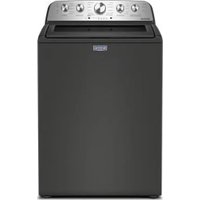

- INSTALLATION INSTRUCTIONS
- INSTRUCTIONS D'INSTALLATION
- TABLE DES MATIÈRES
- Page
- Your safety and the safety of others are very important.
- DANGER
- WARNING
- WARNING - "Risk of Fire"
- FOR YOUR SAFETY
- ARNING:
- FIRE OR EXPLOSION HAZARD
- IMPORTANT SAFETY INSTRUCTIONS
- SAVE THESE INSTRUCTIONS
- Tools Needed:
- Parts Supplied:
- ALTERNATE PARTS AND ACCESSORIES
- Alternate Parts
- Accessories
- Clearances
- STACKED WASHER/GAS DRYER INSTALLATION REQUIREMENTS
- WARNING
- Explosion Hazard
- You will need:
- Stacked washer/gas dryer installation clearances:
- When installing a gas dryer:
- Recessed Area Installation Instructions
- Electrical Shock Hazard
- GROUNDING INSTRUCTIONS
- AWARNING
- STACKED WASHER/ELECTRIC DRYER INSTALLATION REQUIREMENTS
- Stacked washer/electric dryer installation clearances
- Recessed Area and Closet Installation Instructions
- For a grounded, cord-connected washer:
- For a permanently connected washer:
- Dryer Electrical Requirements
- It is your responsibility:
- Electrical Connection
- Electric Dryer Power Supply Cord
- Fire Hazard
- If using a power supply cord:
- If your outlet looks like this:
- If connecting by direct wire:
- Rigid metal vent:
- Flexible metal vent: (Acceptable only if accessible to clean)
- Elbows:
- Clamps:
- Improper venting can cause moisture and lint to collect indoors, which may result in:
- DRYER VENTING REQUIREMENTS
- Vent Hoods
- 411(102mm) Diameter Exhaust Hoods
- Vent System Length
- Maximum Vent Length/Vent Connection
- Connect Vent
- If an Exhaust Hood Cannot be Used
- Multiple Dryer Venting
- DRYER GAS SUPPLY REQUIREMENTS
- Type of Gas
- Gas Supply Line
- Recommended Method
- Gas Supply Pressure Testing
- Alternate Method
- Shut-off valve required
- Flexible Metal Appliance Connector
- Rigid Pipe Connection
- Remove Transport System
- INSTALLING STACKED WASHER/DRYER
- Connect Inlet Hoses
- Connect Inlet Hoses to Water Facets
- Clear Water Lines
- Connect Inlet Hoses to Washer
- Route Drain Hose
- Remove drain hose from the washer drum
- Laundry tub drain or standpipe drain
- To keep drain water from going back into the washer:
- Floor drain
- Secure Drain Hose
- NOTES:
- Standpipe drain system - wall or floor
- Laundry tub drain system
- Floor drain system
- Strain Relief
- Strain Relief (Direct Wire)
- ELECTRIC DRYER ELECTRICAL CONNECTIONS
- Connection Options
- Power Cord
- Direct Wire
- Connecting 4-Wire Connection: Power Supply Cord
- Standard Power Supply Cord Connectors
- Connecting Ground and Neutral Wires
- Connecting Direct Wire Ground
- Connecting Remaining Wires
- Connecting 3-Wire Connection: Power Supply Cord
- Standard Power Cord Connectors
- Connecting Neutral Wire
- Connecting 4-Wire Connection: Direct Wire
- Connecting 4-Wire Connection: Direct Wire (cont.)
- Connecting Ground and Neutral Wires (cont.)
- Connecting 3-Wire Connection: Direct Wire
- Use where local codes permit connecting cabinet-ground conductor to neutral wire.
- Connecting 3-Wire Connection: Optional
- Leveling Stacked Washer/Dryer
- Leveling Stacked Washer/Dryer (cont.)
- Complete Installation
- Remove the Door Assembly
- Reverse Hinge
- Replace the Door Assembly
- Reverse the strike
- Reinstall the door
- Washer
- Cleaning the Door Seal/Bellow
- IMPORTANT:
- Maintenance Instructions:
- To clean washer interior:
- STACKED WASHER/DRYER MAINTENANCE INSTRUCTIONS
- Always do the following to maintain washer freshness:
- Cleaning the exterior
- Cleaning the dispenser drawer
- Water inlet hoses
- Dryer
- If dryer does not operate, check the following:
- IF YOU NEED ASSISTANCE
- General Washer/Dryer User Information
- Scrolling "OUT OF ORDER" Message, Followed by a Failure or Diagnostic Code Showing in Display
- "0 MINUTES" Showing in Display
- Cold Start (Initial first use)
- ELECTRONIC CONTROL SETUP INSTRUCTIONS
- Warm Start (after power failure)
- Washer Door Lock
- Pricing
- There are four (4) types of dryer pricing:
- Fixed "Vend" Pricing
- Accumulator Pricing
- Fixed Cycle With Top Off Pricing
- Free Cycles
- Debit Card Ready
- Control Set-up Procedures
- How to Use the Buttons to Program the Controls
- Washer:
- Dryer:
- Start Operating Set-up
- MAYTAG COMMERCIAL LAUNDRY LIMITED WARRANTY MHN33PDCWW, MHN33PDCXW, MHN33PDCGW, MHN33PRCWW, MHN33PNCGW
- SEVEN YEAR LIMITED WARRANTY
- WHAT IS COVERED
- WHAT IS NOT COVERED
- FIVE YEAR LIMITED WARRANTY (PARTS ONLY - LABOR NOT INCLUDED)
- SIXTH THROUGH SEVENTH YEAR LIMITED WARRANTY (CERTAIN COMPONENT PARTS ONLY - LABOR NOT INCLUDED)
- DISCLAIMER OF IMPLIED WARRANTY
- DISCLAIMER OF REPRESENTATIONS OUTSIDE OF WARRANTY
- LIMITATION OF REMEDIES; EXCLUSION OF INCIDENTAL AND CONSEQUENTIAL DAMAGES
Brand : MAYTAG
Model : MLE22PDAYW
Category : Washing machine