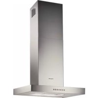
USER MANUAL EFC60640X ELECTROLUX
Welcome to the world of Electrolux
Thank you for choosing a first class product from Electrolux, which hopefully will provide you with lots of pleasure in the future. The Electrolux ambition is to offer a wide variety of quality products that make your life more comfortable. You find some examples on the cover in this manual. Please take a few minutes to study this manual so that you can take advantage of the benefits of your new machine. We promise that it will provide a superior User Experience delivering Ease-of-Mind. Good luck!
ES
RECOMMENDATIONS AND SUGGESTIONS
Installation
- The manufacturer will not be held liable for any damages resulting from incorrect or improper installation.
- The minimum safety distance between the cooker top and the extractor hood is 650 mm (some models can be installed at a lower height, please refer to the paragraphs on working dimensions and installation).
- Check that the mains voltage corresponds to that indicated on the rating plate fixed to the inside of the hood.
- For Class I appliances, check that the domestic power supply guarantees adequate earthing.
Connect the extractor to the exhaust flue through a pipe of minimum diameter 120 mm. The route of the flue must be as short as possible.
- Do not connect the extractor hood to exhaust ducts carrying combustion fumes (boilers, fireplaces, etc.).
- If the extractor is used in conjunction with non-electrical appliances (e.g. gas burning appliances), a sufficient degree of aeration must be guaranteed in the room in order to prevent the backflow of exhaust gas. The kitchen must have an opening communicating directly with the open air in order to guarantee the entry of clean air.
Use
- The extractor hood has been designed exclusively for domestic use to eliminate kitchen smells.
- Never use the hood for purposes other than for which it has been designed.
- Never leave high naked flames under the hood when it is in operation.
- Adjust the flame intensity to direct it
onto the bottom of the pan only, making sure that it does not engulf the sides.
- Deep fat fryers must be continuously monitored during use: overheated oil can burst into flames.
- Do not flambé under the range hood; risk of fire
- This appliance is not intended for use by persons (including children) with reduced physical, sensory or mental capabilities, or lack of experience and knowledge, unless they have been given supervision or instruction concerning use of the appliance by a person responsible for their safety.
- Children should be supervised to ensure that they do not play with the appliance.
Maintenance
- Switch off or unplug the appliance from the mains supply before carrying out any maintenance work.
- Clean and/or replace the Filters after the specified time period (Fire hazard).
- Clean the hood using a damp cloth and a neutral liquid detergent.
The symbol on the product or on its packaging indicates that this product may not be treated as household waste. Instead it shall be handed over to the applicable collection point for the recycling of electrical and electronic equipment. By ensuring this product is disposed of correctly, you will help prevent potential negative consequences for the environment and human health, which could otherwise be caused by inappropriate waste handling of this product. For more detailed information about recycling of this product, please contact your local city office, your household waste disposal service or the shop where you purchased the product.
CHARACTERISTICS
Dimensions
EN
Components
Ref. Q.ty Product Components
1 1 Hood Body, complete with: Controls, Light, Blower, Filters
2 1 Telescopic Chimney comprising: 2.1 1 Upper Section 2.2 1 Lower Section 91 Reducer Flange Ø 150-120 mm 10 1 Damper Ø 150 14.1 2 Air Outlet Connection Extension 15 1 Air Outlet Connection
Ref. Q.ty Installation Components
7.2.1 2 Upper Chimney Section Fixing Brackets 7.3 1 Air Outlet Connection Support 11 6 Wall Plugs 12a 6 Screws 4.2 x 44.4 12c 6 Screws 2.9 x 9.5
Q.ty Documentation
1 Instruction Manual

INSTALLATION
Wall drilling and bracket fixing
Wall marking:
- Draw a vertical line on the supporting wall up to the ceiling, or as high as practical, at the centre of the area in which the hood will be installed.
- Draw a horizontal line at 650 mm above the hob.
- Place bracket 7.2.1 on the wall as shown, about 1-2 mm from the ceiling or upper limit, aligning the centre (notch) with the vertical reference line.
- Mark the wall at the centres of the holes in the bracket.
- Place bracket 7.2.1 on the wall as shown at X mm below the first bracket (X = height of the upper chimney section supplied), aligning the centre (notch) with the vertical line.
- Mark the wall at the centres of the holes in the bracket.
- Mark a reference point as indicated at 116 mm from the vertical reference line and 330 mm above the horizontal reference line.
- Repeat this operation on the other side.
- Drill 8 mm diameter holes at all the centre points marked.
- Insert the wall plugs 11 in the holes.
Fix the lower bracket 7.2.1 using the 12a screws (4.2 x 44.4) supplied.
Fix the upper bracket 7.2.1 and the air outlet connection support 7.3 together using the 2 screws 12a (4.2 x 44.4) supplied.
- Insert the two screws 12a (4.2 x 44.4) supplied in the hood body fixing holes, leaving a gap of 5-6 mm between the wall and the head of the screw.

Hood body installation
- Before attaching the hood body, tighten the two screws Vr located on the hood body mounting points.
- Hook the hood body onto the screws 12a.
- Fully tighten support screws 12a.
- Adjust screws Vr to level the hood body
Connection in Ducting Version
When installing the ducting version, connect the hood to the chimney using either a flexible or rigid pipe of diameter 150 or 120 mm, the choice of which is left to the installer.
To install a 150 mm pipe
To install the damper 10, fix the pipe in position using sufficient pipe clamps (not supplied).
To install a 120 mm pipe
- To install a 120 mm air exhaust connection, insert the reducer flange 9 on the damper 10. Fix the pipe in position using sufficient pipe clamps (not supplied).
- Remove any activated charcoal filters.
Connection in Recycling Version
- Insert the connection extension pieces laterally 14.1 in connection 15.
- Insert the Connector 15 into the Support bracket 7.3 and fix it with a screw.
- Make sure that the outlet of the extension pieces 14.1 is horizontally aligned with the chimney outlets.
- Connect the air outlet connection 15 to the hood body outlet using either a flexible or rigid pipe of 150 mm diameter, the choice of which is left to the installer.
- Ensure that the activated charcoal filters have been inserted.


Electrical Connection
- Connect the hood to the mains through a two-pole switch having a contact gap of at least 3 mm.
- Remove the grease filters (see paragraph Maintenance) being sure that the connector of the feeding cable is correctly inserted in the socket placed on the side of the fan.
Chimney assembly
Upper Chimney
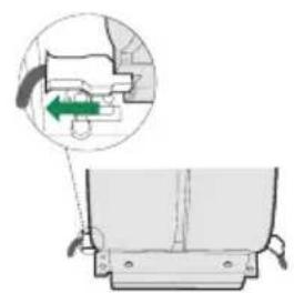
- Slightly widen the two sides of the upper flue and hook them behind the brackets 7.2.1, making sure that they are well seated.
- Secure the sides to the brackets by using the 4 screws 12c (2.9 x 9.5) supplied.
- Make sure that the outlet of the extension pieces is aligned with the chimney outlets.
Lower Chimney
- Slightly widen the two sides of the flue and hook them between the upper flue and the wall, making sure that they are well seated. Fix the lower part laterally to the hood body by using the 2 screws 12c (2.9 x 9.5) supplied.

USE
The hood can be switched on by pushing directly onto the requested speed without firstly having to select the 0/1 button.

| Touch control | Basic functions Indicator lights | |
| Dual Function |
| L | When briefly pressed it switches the lighting system on and off. | Touch control unlit | Lights off |
| When pressed for 2 seconds it starts the lighting system in "courtesy light" mode. The lamps are fed at a reduced power of approximately 5W. Such function can be stopped by pressing the touch control for 2 seconds or just by pressing it shortly in order to return to the normal lighting mode. In courtesy light mode the touch control is not lit. | Touch control lit | Lights on |
| Touch control unlit | Courtesy light on |
| T1 | When pressed the motor is stopped, regardless of the speed it is set to. | Touch control lit | Motor on |
| Touch control unlit | Motor off |
| T2 | When pressed the motor is set to the first speed | Touch control lit |
| T3 | By a brief pressing the motor is set to the second speed. | Touch control lit | Second speed on |
| By pressing the touch control for approximately 2 seconds the Delay function is enabled, i.e delayed shutdown of the appliance ensuring a complete elimination of the residual odours. This function can be activated at OFF-position and at 1°, 2° and 3°speeds. It can be stopped in advance by pressing any of the touch controls (T) with the exception of T3. The Delay function works according to the following scheme: 1°speed / OFF = 20 minuets 2°speed = 15 minutes 3°speed = 5 minutes | Flashing touch control | Delay function on |
| T4 | When pressed the motor is set to the third speed | Touch control lit |
| T5 | When pressed the motor is set to the intensive speed timed to 5 minutes. At the end of 5 minutes of intensive speed the hood starts again at the speed it was set to previously. In case the hood is set to the intensive speed directly from OFF-state it will then start from the first speed after 5 minutes of intensive speed. | Touch control lit |
| F | When pressed for 4 seconds it resets the filter alarm signal indicated by flashing of the touch control T1. This procedure can be carried out only when the motor is stopped. | Touch control lit | Metal grease filters saturation alarm. Metal grease filters need to be washed. The alarm starts up after 100 working hours. |
| Flashing touch control | Charcoal filter saturation alarm. Charcoal filter has to be replaced and metal grease filters washed. The alarm starts up after 200 working hours. (Activation; check the paragraph "Charcoal filter") |
MAINTENANCE
Alarm reset
- Stop the motor.
- Press the F touch control for at least 4 seconds until the T1 touch control flashes.
Cleaning the filters
- Filters can be washed in the dishwasher. They need to be washed every 2 months or even more frequently in case of particularly intensive use of the hood.
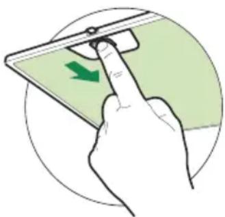
- Remove the filters one by one by pushing them laterally and simultaneously pulling downwards.
- Any kind of bending of the filters has to be avoided when washing them. Before fitting them again into the hood, make sure that they are completely dry. (The colour of the filter surface may change over time, but this has no influence on the filter efficiency.)
- When fitting the filters into the hood, pay attention that they are placed in the correct position and that the handle faces outwards.
Replacing the Charcoal Filter
This filter cannot be washed or regenerated, and must be replaced when the F touch control starts to flash, or at least once every 4 months. The alarm is only triggered when the motor is on.
Enabling/Disabling the alarm signal
- In Recirculation Version Hoods, the Filter saturation Alarm must be enabled at the time of installation or later.
- Switch off the lights and the motor.
- Disconnect the mains power supply to the hood by removing the motor unit power supply cable connector, switching off the power supply at the Mains or turning the Main switch off.
- Restore the connection, pressing and holding T2.
- Release the touch control, touch controls L, T2 and F will light up normally.
- Within 3 seconds press the touch control F until the key itself flashes to confirm as follows:
- 2 flashes - Charcoal Filter saturation Alarm ENABLED
- 1 flash - Charcoal Filter saturation Alarm DISABLED
Reset the alarm signal
- Stop the motor.
- Press the touch control F for at least 4 seconds, until the touch control T1 flashes.
Replace the Filter
- Remove the metal grease filters.
- Remove the saturated charcoal filter, turning the fasteners provided.
- Fit the new filter and fasten it in its correct position.
- Put the metal grease filters in their seats.
Light replacement
20 W halogen light.
- Remove the snap-on lamp cover by levering it from under the metal ring, supporting it with one hand.
- Remove the halogen lamp from the lamp holder by pulling gently.
- Replace the lamp with a new one of the same type, making sure that you insert the two pins properly into the housings on the lamp holder.
- Replace the snap-on lamp cover.


ADVICE AND SUGGESTIONS
INSTALLATION
Ref. Installation parts