
CD30675 - Basket CONSTRUCTA - Free user manual and instructions
Find the device manual for free CD30675 CONSTRUCTA in PDF.
| Product type | Built-in extractor hood |
| Brand | Constructa |
| Model | CD30675 |
| Width | 60 cm or 90 cm depending on version |
| Minimum cabinet depth | 320 mm |
| Minimum cabinet height | 390 mm |
| Maximum weight | 18 kg |
| Power supply | 220-240 V, 50 Hz, 1.30 m cable |
| Extraction modes | Air extraction or recirculation (charcoal filter optional) |
| Suction speeds | 3 speeds + intensive speed (automatic return after 6 min) |
| Lighting | Halogen lamps (HSGST/C/UB-20-230-G9) or LED depending on version |
| Grease filter | Metal, dishwasher-safe or hand-washable, clean every 2 months |
| Charcoal filter | Optional for recirculation mode (ref. 11008080) |
| Control | By filter drawer or buttons depending on variant |
| Automatic shut-off function | Yes, after 10 min (fan run-on) |
| Maximum cabinet temperature | 90 °C |
| Minimum safety distance | According to hob (see manual) |
| Material | Stainless steel, lacquered, aluminium, plastic, glass (depending on parts) |
| After-sales service | 0800 222 145 (BE), 01 40 10 12 00 (FR), 0848 840 040 (CH) |
| Available accessories | Recirculation kit (CZ5145X0), stainless steel handle strip (CZ5760X0 or CZ5790X0) |
Frequently Asked Questions - CD30675 CONSTRUCTA
User questions about CD30675 CONSTRUCTA
0 question about this device. Answer the ones you know or ask your own.
Ask a new question about this device
Download the instructions for your Basket in PDF format for free! Find your manual CD30675 - CONSTRUCTA and take your electronic device back in hand. On this page are published all the documents necessary for the use of your device. CD30675 by CONSTRUCTA.
USER MANUAL CD30675 CONSTRUCTA
[en] Instructions for installation and use 15
Störungen, was tun?......7
Kundendienst 8
MONTAGEANLEITUNG 9
natural_image
Simple line drawing of a house with a checkmark and airflow indicators (no text or symbols)natural_image
Pure electrical control panel diagram without any text, numbers, or symbolsErläuterung
Licht Ein/Aus
① Lüfter Ein/Aus
Hinweise
natural_image
Illustration of a hand holding a small rectangular object with a transparent frame, partially enclosed by a metal frame (no text or symbols visible)natural_image
Illustration of hands holding a tool, no text or symbols present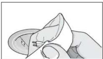
natural_image
Illustration of a hand holding a small object, possibly a tool or device, with no visible text or symbols.Gerätebreite 60cm:
natural_image
Illustration of various mechanical parts with dimension annotations (4x, 2x) and no readable text or symbolsGerätebreite 90cm:
natural_image
Simple line drawing of a house with fire and steam, no text or symbols presentnatural_image
Hand inserting a plug into a device component (no text or symbols visible)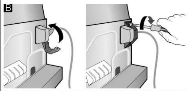
natural_image
Two-step diagram showing a device being inserted into a housing, with arrows indicating the process (no text or symbols present)Installation
Einbau
natural_image
Diagram of a battery connected to a switch, with an inset showing a close-up of its components (no text or symbols present)natural_image
Mechanical assembly diagram showing a bracket with screws and a 2x ratio indicator (no text or symbols present)natural_image
Illustration of a hand using a tool to adjust a 3D model with a magnified inset showing the model's top view (no text or symbols present)INSTRUCTION MANUAL ....15
Intended use....15
Important safety information ....16
Environmental protection ....17
Operating modes ....18
Operating the appliance....18
Cleaning and maintenance ....19
Trouble shooting....20
After-sales service....21
INSTALLATION INSTRUCTIONS ......22
Important safety information....23
General information....24
Installation....26
INSTRUCTION MANUAL
Additional information on products, accessories, replacement parts and services can be found at wwwConstructa.de and in the online shop wwwConstructa-eshop.com
Intended use
Read these instructions carefully. Only then will you be able to operate your appliance safely and correctly. Retain the instruction manual and installation instructions for future use or for subsequent owners.
The appliance can only be used safely if it is correctly installed according to the safety instructions. The installer is responsible for ensuring that the appliance works perfectly at its installation location.
This appliance is intended for domestic use and the household environment only. The appliance is not intended for use outside. Do not leave the appliance unattended during operation. The manufacturer is not liable for damage which is caused by improper use or incorrect operation.
This appliance is intended for use up to a maximum height of 2000 metres above sea level.
This appliance may be used by children over the age of 8 years old and by persons with reduced physical, sensory or mental capacity or by persons with a lack of experience or knowledge if they are supervised by someone who is responsible for their safety, or have been instructed in how to use the appliance safely and have understood the risks involved in not using it properly.
Children must not play with the appliance. Cleaning and user maintenance must not be performed by children unless they are over 15 years of age and are supervised.
Keep children below the age of 8 years old at a safe distance from the appliance and power cable.
Check the appliance for damage after unpacking it. Do not connect the appliance if it has been damaged in transport.
This appliance is not intended for operation with an external clock timer or a remote control.
⚠️ Important safety information
Read these instructions carefully. Only then will you be able to operate your appliance safely and correctly. Retain the instruction manual and installation instructions for future use or for subsequent owners.
Danger of suffocation!
Packaging material is dangerous to children. Never allow children to play with packaging material.
Danger of death!
Risk of poisoning from flue gases that are drawn back in.
Always ensure adequate fresh air in the room if the appliance is being operated in exhaust air mode at the same time as room air-dependent heat-producing appliance is being operated.
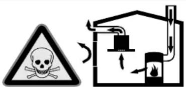
Room air-dependent heat-producing appliances (e.g. gas, oil, wood or coal-operated heaters, continuous flow heaters or water heaters) obtain combustion air from the room in which they are installed and discharge the exhaust gases into the open air through an exhaust gas system (e.g. a chimney).
In combination with an activated vapour extractor hood, room air is extracted from the kitchen and neighbouring rooms - a partial vacuum is produced if not enough fresh air is supplied. Toxic gases from the chimney or the extraction shaft are sucked back into the living space.
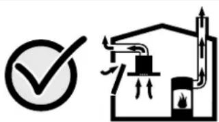
- Adequate incoming air must therefore always be ensured.
■ An incoming/exhaust air wall box alone will not ensure compliance with the limit.
Safe operation is possible only when the partial vacuum in the place where the heat-producing appliance is installed does not exceed 4 Pa (0.04 mbar). This can be achieved when the air needed for combustion is able to enter through openings that cannot be sealed, for example in doors, windows, incoming/exhaust air wall boxes or by other technical means.
natural_image
Simple line drawing of a checkmark and a schematic diagram of a gas stove (no text or symbols)In any case, consult your responsible Master Chimney Sweep. He is able to assess the house's entire ventilation setup and will suggest the suitable ventilation measures to you.
Unrestricted operation is possible if the vapour extractor hood is operated exclusively in the circulating-air mode.
Risk of fire!
■ Grease deposits in the grease filter may catch fire.
Clean the grease filter at least every 2 months.
Never operate the appliance without the grease filter.
- Grease deposits in the grease filter may catch fire. Never work with naked flames close to the appliance (e.g. flambéing). Do not install the appliance near a heat-producing appliance for solid fuel (e.g. wood or coal) unless a closed, non-removable cover is available. There must be no flying sparks.
- Hot oil and fat can ignite very quickly. Never leave hot fat or oil unattended. Never use water to put out burning oil or fat. Switch off the hotplate. Extinguish flames carefully using a lid, fire blanket or something similar.
- When gas burners are in operation without any cookware placed on them, they can build up a lot of heat. A ventilation appliance installed above the cooker may become damaged or catch fire. Only operate the gas burners with cookware on them.
- Operating several gas burners at the same time gives rise to a great deal of heat. A ventilation appliance installed above the cooker may become damaged or catch fire. Never operate two gas burners simultaneously on the highest flame for longer than 15 minutes. One large burner of more than 5 kW (wok) is equivalent to the power of two gas burners.
Risk of burns!
The accessible parts become very hot when in operation. Never touch hot parts. Keep children at a safe distance.
Risk of injury!
■ Components inside the appliance may have sharp edges. Wear protective gloves.
■ Items placed on the appliance may fall down. Do not place any objects on the appliance.
■ The light emitted by LED lights is very dazzling, and can damage the eyes (risk group 1). Do not look directly into the switched on LED lights for longer than 100 seconds.
Risk of electric shock!
- A defective appliance may cause electric shock. Never switch on a defective appliance. Unplug the appliance from the mains or switch off the circuit breaker in the fuse box. Contact the after-sales service.
- Incorrect repairs are dangerous. Repairs may only be carried out and damaged power cables replaced by one of our trained after-sales technicians. If the appliance is defective, unplug the appliance from the mains or switch off the circuit breaker in the fuse box. Contact the after-sales service.
- Do not use any high-pressure cleaners or steam cleaners, which can result in an electric shock.
Causes of damage
Caution!
Risk of damage due to corrosion. Always switch on the appliance while cooking to avoid condensation. Condensate can produce corrosion damage.
Always replace faulty bulbs to prevent the remaining bulbs from overloading.
Risk of damage due to ingress of humidity into the electronic circuitry. Never clean operator controls with a wet cloth.
Surface damage due to incorrect cleaning. Clean stainless steel surfaces in the direction of the grain only. Do not use any stainless steel cleaners for operator controls.
Surface damage due to strong or abrasive cleaning agents. Never use strong and abrasive cleaning agents.
Risk of damage from returning condensate. Install the exhaust duct in such a way that it falls away from the appliance slightly (1° slope).
Environmental protection
Your new appliance is particularly energy-efficient. Here you can find tips on how to save even more energy when using the appliance, and how to dispose of your appliance properly.
Saving energy
■ During cooking, ensure that there is a sufficient supply of air so that the extractor hood can work efficiently and with a low level of operating noise.
■ Adjust the fan speed to the intensity of the cooking fumes. Only use intensive mode where this is required. A lower fan speed means that less energy is consumed.
If there are intensive cooking fumes, select a higher fan speed in good time. If cooking fumes have already spread in the kitchen, the extractor hood must be operated for longer.
■ Switch off the extractor hood if you no longer require it.
■ Switch off the lighting if you no longer require it.
■ Clean and, if required, replace the filter at regular intervals in order to increase the effectiveness of the ventilation system and to prevent the risk of fire.
Environmentally-friendly disposal
Dispose of packaging in an environmentally-friendly manner.
This appliance is labelled in accordance with European Directive 2012/19/EU concerning used electrical and electronic appliances (waste electrical and electronic equipment - WEEE). The guideline determines the framework for the return and recycling of used appliances as applicable throughout the EU.
Operating modes
This appliance can be used in exhaust-air mode or circulating-air mode.
Exhaust air mode
The air which is drawn in is cleaned by the grease filters and conveyed to the exterior by a pipe system.
Note: The exhaust air must not be conveyed into a functioning smoke or exhaust gas flue or into a shaft which is used to ventilate installation rooms which contain heat-producing appliances.
■ Before conveying the exhaust air into a non-functioning smoke or exhaust gas flue, obtain the consent of the heating engineer responsible.
If the exhaust air is conveyed through the outer wall, a telescopic wall box should be used.
Air recirculation
The air which is drawn in is cleaned by the grease filters and an activated carbon filter, and is conveyed back into the kitchen.
Note: To bind odours in air recirculation mode, you must install
Operating the appliance
These instructions apply to several appliance variants. It is possible that individual features are described which do not apply to your appliance.
Note: Switch on the extractor hood when you start cooking and switch it off again several minutes after you have finished cooking. This is the most effective way of removing the kitchen fumes.
Control panel model 1 and 2
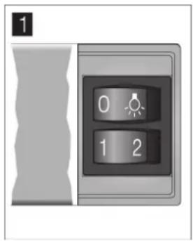
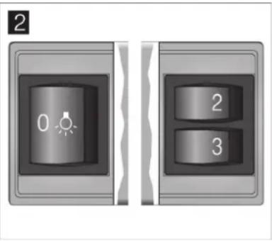
Explanation
0, Light on/off
1 Fan speed 1
2 Fan speed 2
3 Fan speed 3
Setting the fan
Switching on
Pull out the filter pull-out. The fan starts at the selected level.
Press buttons 1, 2 or 3 in order to change the fan strength.
Switching off
Slide the filter pull-out in as far as the limit stop.
Note: When you pull out the filter pull-out again, the fan starts up at the fan speed that was last selected.
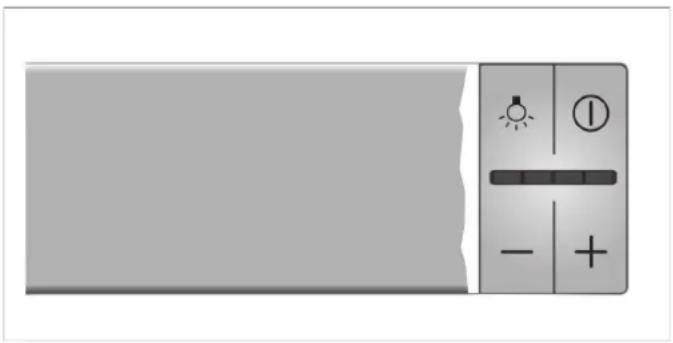
Control panel model 3
natural_image
Close-up of a gray electronic device control panel with indicator lights and buttons (no readable text or symbols)Explanation
Light on/off
① Fan on/off
- Reduces the fan speed
+ Increases the fan speeds/intensive setting
Setting the fan
Switching on
Pull out the filter pull-out and press the ① button. The fan starts at setting 2.
Press the + or - button to change the fan strength.
Switching off
Press the ① button. Slide the filter pull-out in.
Intensive setting
You can use the intensive setting if there is a large build-up of odours and fumes/vapours.
Press the + button until all of the LEDs in the display light up. The intensive setting is activated.
After approx. six minutes, the electronics automatically reduce the fan to a lower setting. If you want to end the intensive setting before the preset time expires, press the - button until the required fan setting is reached.
The run time is limited. The fan is then automatically reduced to a lower fan setting. You can switch back manually at any time.
Fan run-on time
If you slide in the filter pull-out, the run-on time will be activated for as long as the extractor hood is operating.
After approx. 10 minutes, the fan switches off automatically.
Lighting
The lighting can be switched on and off independently of the ventilation.
Press the 🔊 button.
Cleaning and maintenance
Risk of burns!
The appliance will become hot during operation, especially near the bulbs. Allow the appliance to cool down before cleaning.
Risk of electric shock!
Penetrating moisture may result in an electric shock. Clean the appliance using a damp cloth only. Before cleaning, pull out the mains plug or switch off the circuit breaker in the fuse box.
Risk of electric shock!
Do not use any high-pressure cleaners or steam cleaners, which can result in an electric shock.
Risk of injury!
Components inside the appliance may have sharp edges. Wear protective gloves.
Cleaning agents
To ensure that the different surfaces are not damaged by using the wrong cleaning agent, observe the information in the table. Do not use any of the following:
■ Harsh or abrasive cleaning agents,
■ Cleaning agents with a high alcohol content,
■ Hard scouring pads or cleaning sponges,
■ High-pressure cleaners or steam cleaners.
Wash new sponge cloths thoroughly before use.
Follow all instructions and warnings included with the cleaning agents.
Area Cleaning agent
| Stainless steel Hot soapy water: | |
| Clean with a dish cloth and then dry with a soft cloth. | |
| Clean stainless steel surfaces in the grind direction only. | |
| Special stainless steel cleaning products are available from our after-sales service or from specialist retailers. Apply a very thin layer of the cleaning product with a soft cloth. | |
| Painted surfaces Hot soapy water: | |
| Clean using a damp dish cloth and dry with a soft cloth/towel. | |
| Do not use any stainless steel cleaners. | |
Aluminium and plas- Glass cleaner: tic Clean with a soft cloth.
Area Cleaning agent
| Glass Glass cleaner: | |
| Clean with a soft cloth. Do not use a glass scraper. | |
| Controls Hot soapy water: | |
| Clean using a damp dish cloth and dry with a soft cloth/towel. | |
| Risk of electric shock caused by penetrating moisture. | |
| Risk of damage to the electronics from penetrating moisture. Never clean operating controls with a wet cloth. | |
| Do not use any stainless steel cleaners. | |
Cleaning the metal mesh grease filters
These instructions apply to several appliance variants. It is possible that individual features are described which do not apply to your appliance.
Risk of fire!
Grease deposits in the grease filter may catch fire.
Clean the grease filter at least every 2 months.
Never operate the appliance without the grease filter.
Notes
- Do not use any aggressive, acidic or alkaline cleaning agents.
- When cleaning the metal mesh grease filters, also clean the holder for the metal mesh grease filters in the appliance using a damp cloth.
■ The metal mesh grease filters can be cleaned in the dishwasher or by hand.
By hand:
Note: You can use a special grease solvent for stubborn dirt. It can be ordered via the Online Shop.
■ Soak the metal mesh grease filters in a hot soapy solution.
■ Clean the filters with a brush and then rinse them thoroughly.
■ Leave the metal mesh grease filters to drain.
In the dishwasher:
Note: If the metal mesh grease filters are cleaned in the dishwasher, slight discolouration may occur. This has no effect on the function of the metal mesh grease filters.
- Do not clean heavily soiled metal mesh grease filters together with utensils.
- Place the metal mesh grease filters loosely in the dishwasher. The metal mesh grease filters must not be wedged in.
Removing metal grease filter
- Open the lock and fold down the metal grease filter. While doing this, place your other hand under the metal grease filter.
- Take the metal grease filter out of the holder.
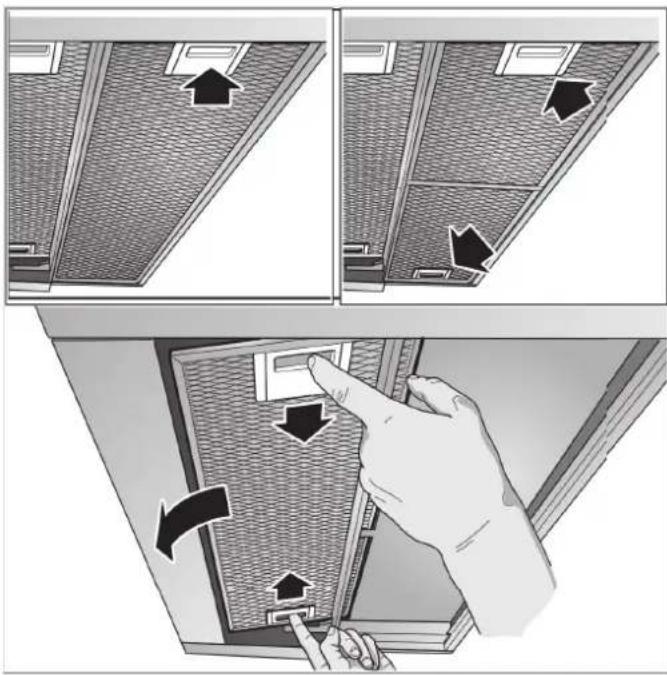
Notes
■ Fat may accumulate in the bottom of the metal grease filter.
■ Hold the metal grease filter level to prevent grease from dripping out.
- Clean the metal grease filter.
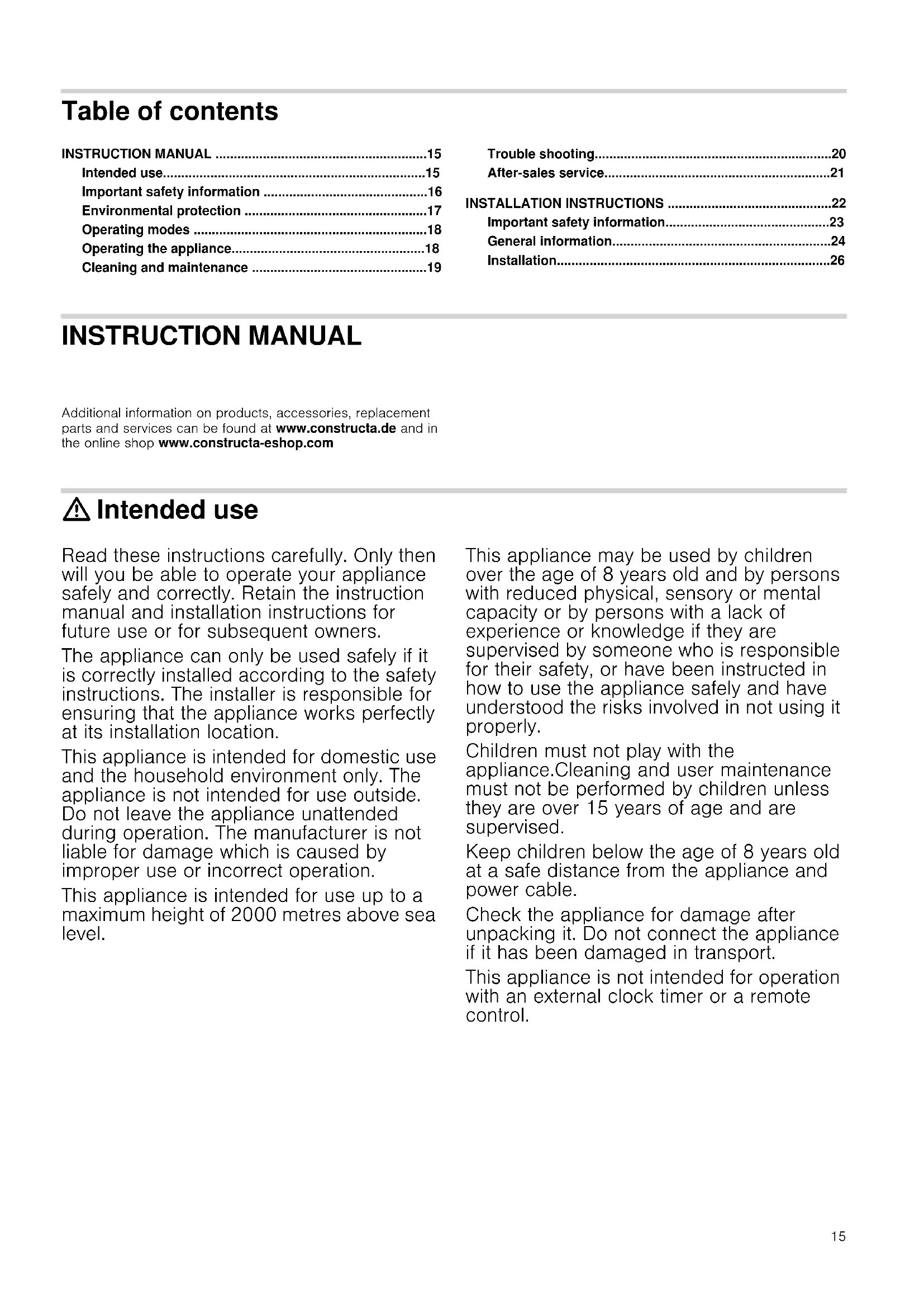
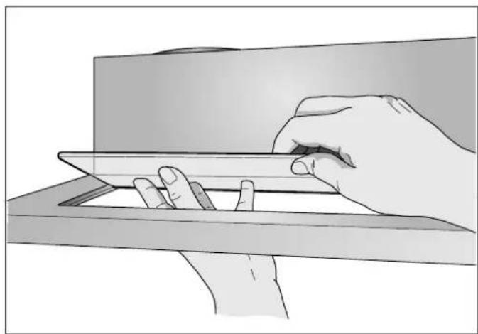
On appliances with a glass plate in the filter pull-out:
■ The glass plate can be removed easily and can be cleaned in the dishwasher.
■ To remove it, carefully lift the glass plate.
natural_image
Illustration of a hand using a tool to cut or install a rectangular object, no text or symbols presentInstalling the metal mesh grease filter
- Insert the metal mesh grease filter.
While doing this, place the other hand under the metal mesh grease filter. - Fold the metal mesh grease filter upwards, locking it in place.
Trouble shooting
Malfunctions often have simple explanations. Please read the following notes before calling the after-sales service.
Risk of electric shock!
Incorrect repairs are dangerous. Repairs may only be carried out and damaged power cables replaced by one of our trained after-sales technicians. If the appliance is defective, unplug the appliance from the mains or switch off the circuit breaker in the fuse box. Contact the after-sales service.
Malfunction table
| Problem Possible cause Solution | ||
| The appliance does not work | The plug is not plugged in. | Connect the appliance to the electricity supply |
| Power cut Check whether other kitchen appliances are working | ||
| Faulty fuse Check in the fuse box to make sure that the fuse for the appliance is OK | ||
| The lighting does not work. | The bulbs are faulty. | For information on changing the bulbs, see the "Replacing Bulbs" section. |
Replacing bulbs
These instructions apply to several appliance variants. It is possible that individual features are described which do not apply to your appliance.
Risk of burns!
Halogen bulbs become very hot when switched on. There is still a risk of burning for some time after they have been switched off. Allow the halogen bulbs to cool down before replacing them.
Risk of electric shock!
When changing the bulbs, the bulb socket contacts are live. Before changing the bulb, unplug the appliance from the mains or switch off the circuit breaker in the fuse box.
Important! Only use bulbs of the same type and wattage.
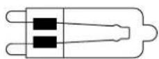
HSGST/C/UB-20-230-G9
Replacing halogen bulbs
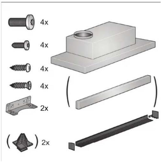
Note: When inserting halogen bulbs, do not touch the glass tube. Use a clean cloth to insert the halogen bulbs.
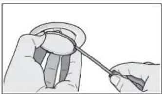
- Carefully remove the bulb ring using a suitable tool.
- Pull out the bulb and replace it with a bulb of the same type.
natural_image
Illustration of hands holding a tool, no text or symbols present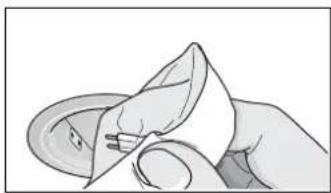
natural_image
Illustration of a hand holding a folded paper or plastic sheet (no text or symbols visible)- Insert the bulb cover.
- Insert the mains plug or switch on the fuse again.
After-sales service
Our after-sales service is there for you if your appliance needs to be repaired. We will always find the right solution in order to avoid unnecessary visits from a service technician.
When calling us, please give the product number (E no.) and the production number (FD no.) so that we can provide you with the correct advice. The rating plate with these numbers can be found inside the appliance (remove the metal mesh grease filter to gain access).
You can make a note of the numbers of your appliance and the telephone number of the after-sales service in the space below to save time should it be required.
E no. FD no.
After-sales serviceO
Please be aware that a visit by an after-sales engineer will be charged if a problem turns out to be the result of operator error, even during the warranty period.
Please find the contact data of all countries in the enclosed customer service list.
Rely on the professionalism of the manufacturer. You can therefore be sure that the repair is carried out by trained service technicians who carry original spare parts for your appliances.
LED lights
Defective LED lights may be replaced by the manufacturer, their customer service or a qualified technician (electrician) only.
Risk of injury!
The light emitted by LED lights is very dazzling, and can damage the eyes (risk group 1). Do not look directly into the switched on LED lights for longer than 100 seconds.
Accessories
(not included in the scope of delivery)
Note: These instructions apply to several appliance models. It may be the case that an optional accessory that is listed does not apply for your appliance.
Note: Observe the installation instructions in the accessory.
Accessories Order number
| Basic equipment: | |
| Starter set for circulating-air mode | CZ5145X0 |
| Throw-away filter for starter set | 11008080 |
| Handle strip: 60 cm: | |
| Stainless steel CZ5760X0 | |
| Handle strip: 90 cm: | |
| Stainless steel CZ5790X0 | |
INSTALLATION INSTRUCTIONS
These instructions apply to several appliance variants. It is possible that individual features are described which do not apply to your appliance.
■ This appliance is installed in a upper cabinet.
■ Follow the enclosed installation instructions for additional special accessories (e.g. for circulating-air mode).
■ The surfaces of the appliance are sensitive. Avoid damaging them during installation.
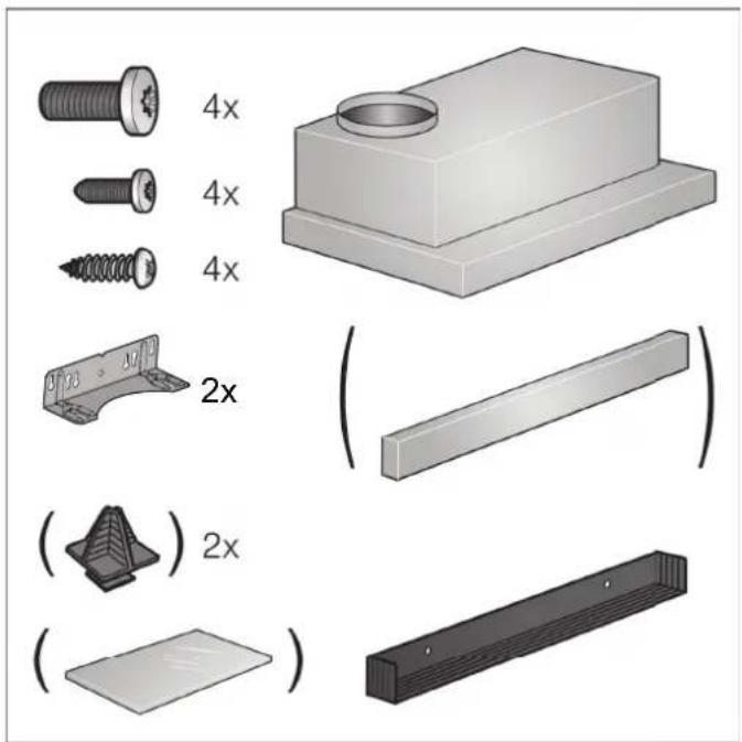
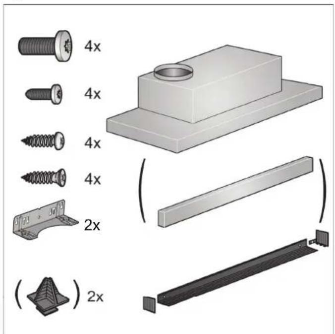
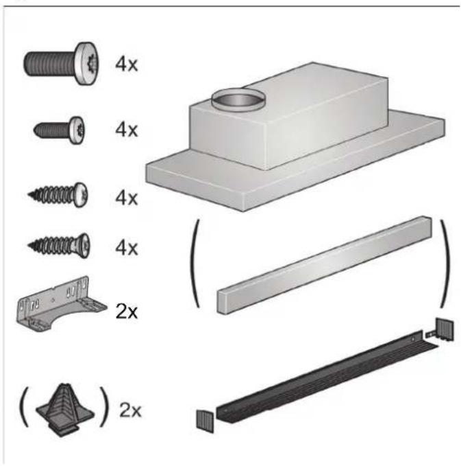
Appliance width 60 cm:
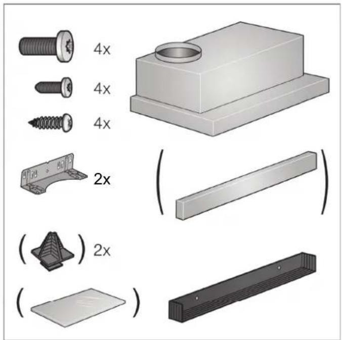
natural_image
Illustration of various mechanical parts including screws, bolts, and a base plate with 2x magnified views (no text or symbols)Appliance width, 90 cm:
⚠️ Important safety information
Read these instructions carefully. Only then will you be able to operate your appliance safely and correctly. Retain the instruction manual and installation instructions for future use or for subsequent owners.
The appliance can only be used safely if it is correctly installed according to the safety instructions. The installer is responsible for ensuring that the appliance works perfectly at its installation location.
The width of the extractor hood must correspond at least with the width of the hob.
For the installation, observe the currently valid building regulations and the regulations of the local electricity and gas suppliers.
When conveying the exhaust air, official and legal regulations (e.g. state building regulations) must be followed.
Risk of death!
Risk of poisoning from flue gases that are drawn back in. The exhaust air must not be conveyed into a functioning smoke or exhaust gas flue or into a shaft which is used to ventilate installation rooms that contain heating appliances. If the exhaust air is to be conveyed into a non-functioning smoke or exhaust gas flue, you must obtain the consent of the heating engineer responsible.
Danger of death!
Risk of poisoning from flue gases that are drawn back in.
Always ensure adequate fresh air in the room if the appliance is being operated in exhaust air mode at the same time as room air-dependent heat-producing appliance is being operated.
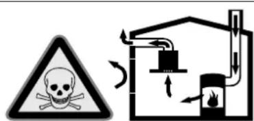
Room air-dependent heat-producing appliances (e.g. gas, oil, wood or coal-operated heaters, continuous flow heaters or water heaters) obtain combustion air from the room in which they are installed and discharge the exhaust gases into the open air through an exhaust gas system (e.g. a chimney).
In combination with an activated vapour extractor hood, room air is extracted from the kitchen and neighbouring rooms - a partial vacuum is produced if not enough fresh air is supplied. Toxic gases from the chimney or the extraction shaft are sucked back into the living space.
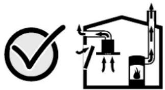
■ Adequate incoming air must therefore always be ensured.
- An incoming/exhaust air wall box alone will not ensure compliance with the limit. Safe operation is possible only when the partial vacuum in the place where the heat-producing appliance is installed does not exceed 4 Pa (0.04 mbar). This can be achieved when the air needed for combustion is able to enter through openings that cannot be sealed, for example in doors, windows, incoming/exhaust air wall boxes or by other technical means.
natural_image
Simple line drawing of a house with a checkmark and airflow indicators (no text or symbols)In any case, consult your responsible Master Chimney Sweep. He is able to assess the house's entire ventilation setup and will suggest the suitable ventilation measures to you.
Unrestricted operation is possible if the vapour extractor hood is operated exclusively in the circulating-air mode.
Danger of death!
Risk of poisoning from flue gases that are drawn back in. If installing a ventilation system in a room with a heat-producing appliance connected to a chimney/flue, the electricity supply to the hood must be equipped with a suitable safety switch.
Risk of fire!
Grease deposits in the grease filter may catch fire. The specified safety distances must be observed in order to prevent an accumulation of heat. Observe the specifications for your cooking appliance. If gas and electric hobs are operated together, the largest specified distance applies.
Only one side of the appliance may be installed directly next to a high-sided unit or a wall. The distance between the appliance and wall or high-sided unit must be at least 50 mm.
Risk of injury!
■ Components inside the appliance may have sharp edges. Wear protective gloves.
- The appliance may fall down if it has not been properly fastened in place. All fastening components must be fixed firmly and securely.
■ The appliance is heavy. To move the appliance, 2 people are required. Use only suitable tools and equipment.
Risk of electric shock!
Components inside the appliance may have sharp edges. These may damage the connecting cable. Do not kink or pinch the connecting cable during installation.
Risk of electric shock!
It must always be possible to disconnect the appliance from the electricity supply. The appliance must only be connected to a protective contact socket that has been correctly installed. If the plug is no longer accessible once the appliance has been installed, or a fixed connection is required, the installation must have an all-pole isolating switch with a contact gap of at least 3 mm. Only an electrician may install the fixed connection. We recommend installing a residual-current circuit breaker (RCCB) in the appliance's power supply circuit.
Danger of suffocation!
Packaging material is dangerous to children. Never allow children to play with packaging material.
General information
Exhaust air mode
Risk of death!
Risk of poisoning from flue gases that are drawn back in. The exhaust air must not be conveyed into a functioning smoke or exhaust gas flue or into a shaft which is used to ventilate installation rooms that contain heating appliances. If the exhaust air is to be conveyed into a non-functioning smoke or exhaust gas flue, you must obtain the consent of the heating engineer responsible.
If the exhaust air is conveyed through the outer wall, a telescopic wall box should be used.
Exhaust duct
Note: The appliance manufacturer does not provide any warranty for faults attributable to the pipe section.
The appliance achieves its optimum performance by means of a short, straight exhaust air pipe and as large a pipe diameter as possible.
As a result of long, rough exhaust air pipes, many pipe bends or pipe diameters that are smaller than 150 mm, the optimum extraction performance is not achieved and fan noise is increased.
■ The pipes or hoses for laying the exhaust air line must consist of non-combustible material.
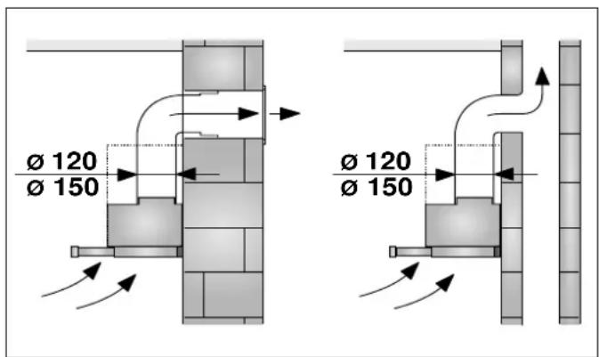
Round pipes
An inner diameter of 150 mm, but at least 120 mm, is recommended.
Flat ducts
The inner cross-section must correspond to the diameter of the round pipes.
150 mm diameter, approx. 177 cm²
120 mm diameter, approx. 113 cm²
■ Flat ducts should not have any sharp deflections.
■ Use sealing strips for different pipe diameters.
Electrical connection
Risk of electric shock!
Components inside the appliance may have sharp edges. These may damage the connecting cable. Do not kink or pinch the connecting cable during installation.
The required connection data can be found on the rating plate inside the appliance; to do this, remove the metal mesh grease filter.
Length of the cable: approx. 1.30 m
This appliance complies with the EC interference suppression regulations.

Risk of electric shock!
It must always be possible to disconnect the appliance from the electricity supply. The appliance must only be connected to a protective contact socket that has been correctly installed. If the plug is no longer accessible once the appliance has been installed, or a fixed connection is required, the installation must have an all-pole isolating switch with a contact gap of at least 3 mm. Only an electrician may install the fixed connection. We recommend installing a residual-current circuit breaker (RCCB) in the appliance's power supply circuit.
Preparing the units
■ The fitted unit must be level and have sufficient load-bearing capacity.
■ The max. weight of the extractor hood is 18 kg.
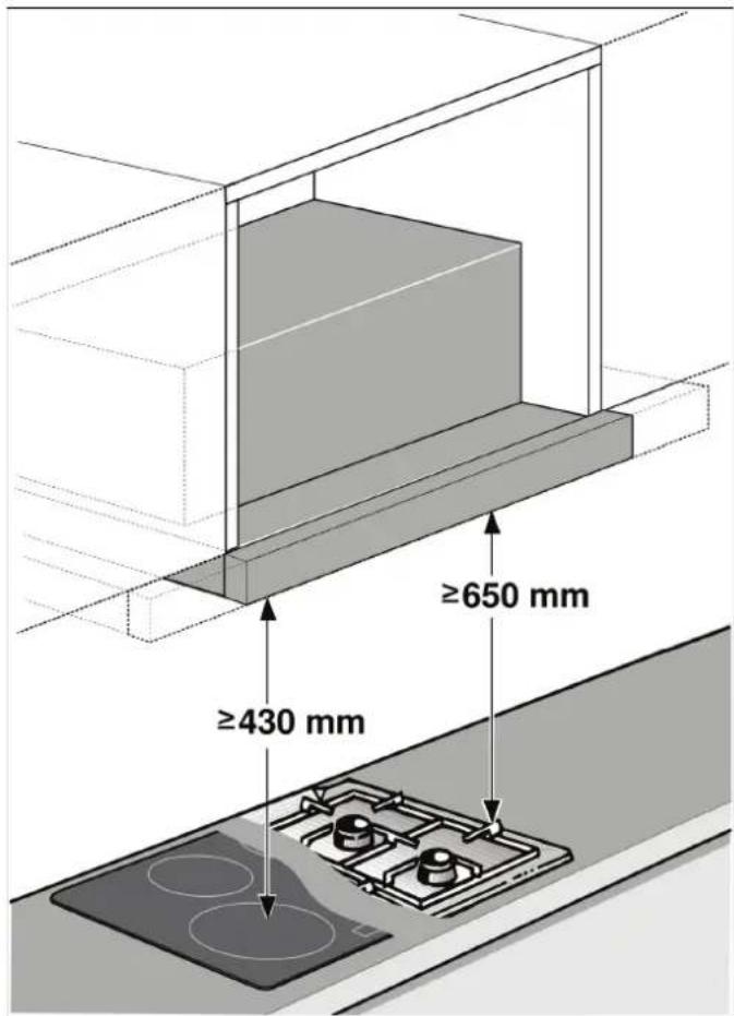
Appliance dimensions and safety clearances
- Observe the appliance's dimensions.
■ Comply with the safety clearances.
If the installation instructions for the gas cooking appliances specify a different distance, the largest distance must always be provided for.
The fitted unit must be heat-resistant up to 90 °C. The fitted unit must still be sturdy after the cut-outs have been made.
To install an upper cabinet, this extractor hood must be provided with the following dimensions:
Width 600 mm
Depth Min. 320 mm
Height Min. 390 mm
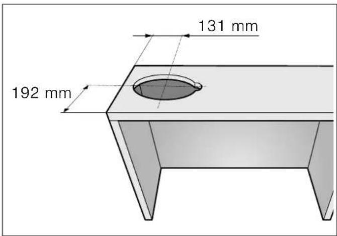
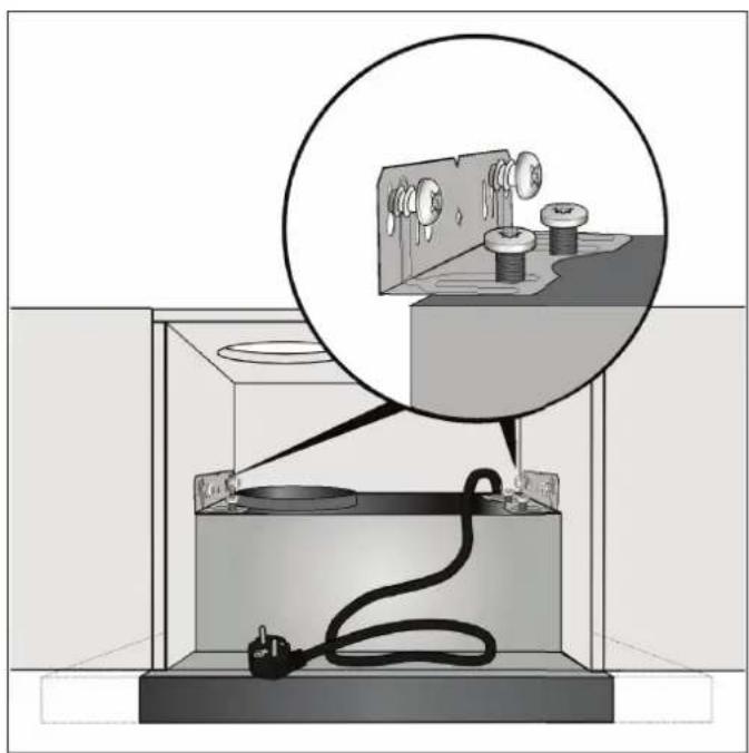
- Make the cut-out for the exhaust air pipe. To do this, make an opening in the ceiling or back wall of the fitted unit with an additional recess for the power cord.
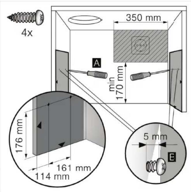
- If the cabinet base is present, remove this. Mark the securing points on the inside of the cabinet and pre-cut the holes using a piercer. Use the enclosed template to mark the securing points. A
- Screw in the four enclosed screws for the angle bracket up to 5 mm. B
Preparing the appliance
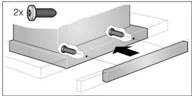
A handle strip must be screwed to the filter pull-out. This handle strip can be one that is provided with the appliance, or one that is available as an accessory.
- Use the screws provided to secure the handle strip to the filter pull-out.
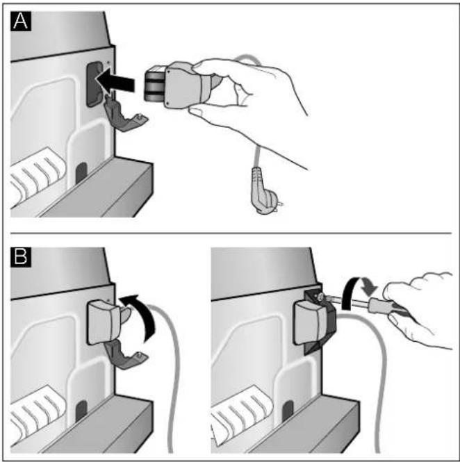
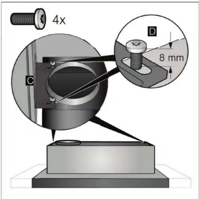
- Connect the power cord provided to the appliance. A
- Use the strain relief to secure the power cord in place. B
- Screw the two angle brackets to the appliance. Ensure that the screws are positioned correctly. C Screw in the screws until 8 mm of the threaded section is still protruding. D
Installation
Installation
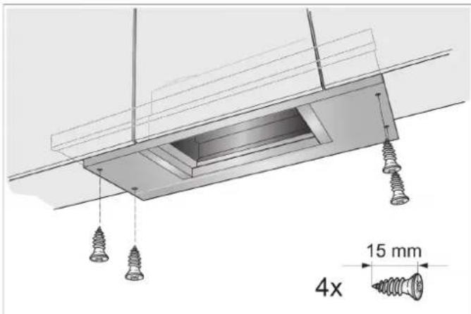
- Use the angle brackets to hang the appliance on the screws and align it.
natural_image
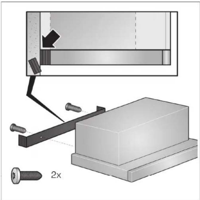
Diagram of a battery connected to a circuit board with a magnified inset showing components (no text or symbols present)- Measure the distance from the appliance to the wall and mark this on the filler strip.
-
If required, shorten the filler strip to the required dimension.
-
Remove the appliance and screw in the filler strip.
natural_image
Mechanical assembly diagram showing a bracket with screws and a 2x ratio indicator (no text or symbols present)- Remount the appliance, align it and screw it in place. Carefully screw in all screws.
- Establish the electrical connection.
Note: The extractor hood's housing can be concealed within the upper cabinet. In doing so, you must observe the following:
■ The intermediate floor must not be placed on the extractor hood's housing.
■ The front panel must not be secured to the housing.
- Access must be available in order to change the filter and for after-sales service.
Appliance width, 90 cm:
You must also screw the appliance onto the side upper cabinets.
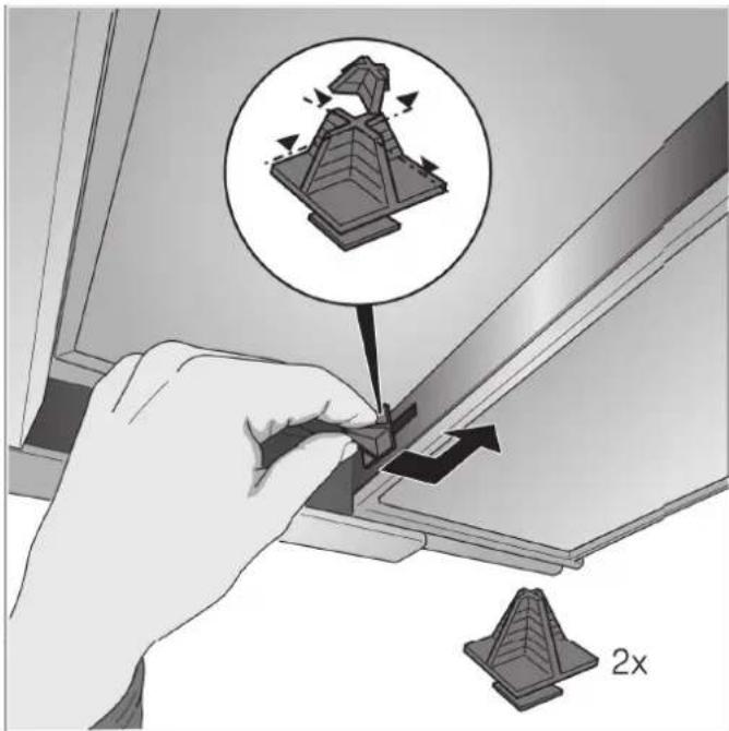
Change the filter pull-out's limit stop
On some versions of the appliance, the limit stop for the filter pull-out can be changed. Spacers are included with these appliances in order to set the appliance's handle strip so that it is flush with the fitted unit.
- Pull the filter pull-out forwards.
- Shorten the spacer to the required dimension and insert it into the specified slot.
natural_image
Illustration of a hand using a tool to adjust a 3D model with an arrow, showing a magnified view of the model (no text or symbols present)Connecting the pipes
Note: If using an aluminium pipe, smooth the connection area beforehand.
Exhaust-air pipe ∅ 150 mm (recommended size)
Attach the exhaust-air pipe directly to the air-pipe connector and seal.
Exhaust-air pipe ∅ 120 mm
- Attach the reducing connector directly to the air-pipe connector.
- Attach the exhaust air pipe to the reducing connector.
- Seal both joints appropriately.
Table des matières
NOTICE D'UTILISATION 28
natural_image
Simple line drawing of a house with a checkmark and airflow indicators (no text or symbols)natural_image
Pure electrical control panel diagram without any text, numbers, or symbolsExplication
Aspiration intensive
natural_image
Architectural detail showing a sloped roof with a black arrow pointing to a window (no text or symbols)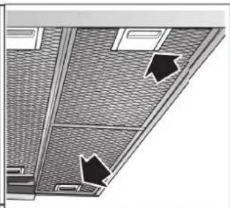
natural_image
Architectural floor plan showing ceiling and window layout with two black arrows pointing to specific areas (no text or symbols present)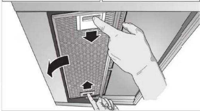
natural_image
Illustration of a hand inserting a device into a rack, showing directional arrows (no text or symbols)Remarques
natural_image
Illustration of a hand using a tool to cut or adjust a rectangular object, no text or symbols presentnatural_image
Illustration of a hand holding a small object with a tool, no text or symbols present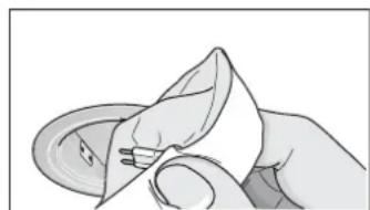
natural_image
Illustration of a hand holding a folded paper or cloth (no text or symbols visible)natural_image
Illustration of various mechanical parts including screws, bolts, and a base plate with 2x magnified views (no text or symbols)natural_image
Simple line drawing of a house with a checkmark and airflow indicators (no text or symbols)natural_image
Hand inserting a plug into a device (no text or symbols visible)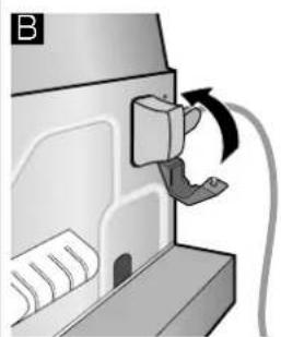
natural_image
Diagram of a printer or printer with a paper feeding into a slot, showing a curved arrow indicating motion (no text or symbols present)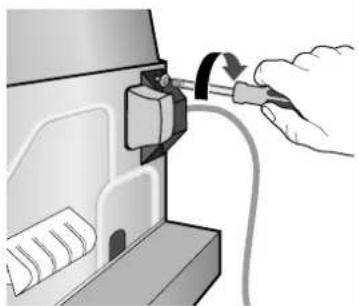
natural_image
Illustration of a hand inserting cable into a device component (no text or symbols visible)Installation
Montage
natural_image
Diagram of a battery cell setup with an inset showing a close-up of its internal components (no text or symbols present)natural_image
Mechanical assembly diagram showing a bracket with screws and a 2x ratio indicator (no text or symbols present)natural_image
Hand inserting a 3D model into a device, with an inset showing the model being rotated (no text or symbols present)natural_image
Simple line drawing of a house with a checkmark and airflow indicators (no text or symbols)natural_image
Pure electrical control panel diagram without any text, numbers, or symbolsToelichting
Licht Aan/Uit
① Ventilator Aan/Uit
Aanwijzingen
natural_image
Illustration of a hand using a tool to cut or install a rectangular object, no text or symbols presentMetalen vetfilter monteren
natural_image
Illustration of hands holding a small object with a tool, no text or symbols present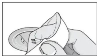
natural_image
Illustration of a hand holding a small object, possibly a tool or device, with no visible text or symbols.Apparaatbreedte 60cm:

natural_image
Illustration of various mechanical parts with dimension annotations (4x, 2x) and no readable text or symbolsApparaatbreedte 90cm:
natural_image
Simple line drawing of a house with a checkmark and airflow indicators (no text or symbols)natural_image
Hand inserting a plug into a device component (no text or symbols visible)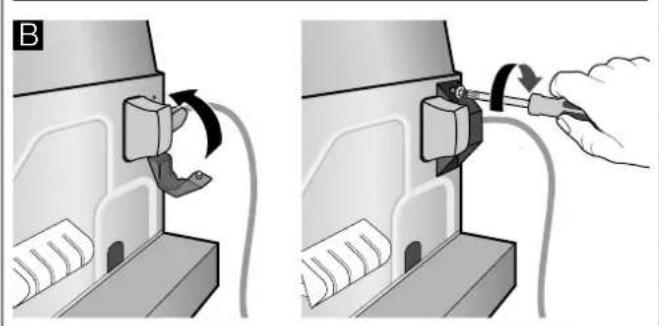
natural_image
Two-step diagram showing a device being inserted into a housing, with arrows indicating rotation and assembly (no text or symbols present)Installatie
Inbouw
natural_image
Diagram of a battery connected to a switch inside a container, with an inset showing a close-up of its components (no text or symbols present)natural_image
Mechanical assembly diagram showing a bracket with screws and a 2x ratio indicator (no text or symbols present)natural_image
Illustration of a hand using a tool to adjust a 3D model with an arrow, showing structural components and a 2x ratio indicator (no text or symbols on the diagram itself)Buisverbindingen bevestigen

- Erläuterung
- Hinweise
- Installation
- Einbau
- INSTRUCTION MANUAL
- Intended use
- ⚠️ Important safety information
- Danger of suffocation!
- Danger of death!
- Risk of fire!
- Clean the grease filter at least every 2 months.
- Risk of burns!
- Risk of injury!
- Risk of electric shock!
- Causes of damage
- Caution!
- Environmental protection
- Saving energy
- Environmentally-friendly disposal
- Operating modes
- Exhaust air mode
- Air recirculation
- Operating the appliance
- Control panel model 1 and 2
- Explanation
- Setting the fan
- Switching on
- Switching off
- Control panel model 3
- Intensive setting
- Fan run-on time
- Lighting
- Cleaning and maintenance
- Cleaning agents
- Cleaning the metal mesh grease filters
- Notes
- By hand:
- In the dishwasher:
- Removing metal grease filter
- Installing the metal mesh grease filter
- Trouble shooting
- Replacing bulbs
- Replacing halogen bulbs
- After-sales service
- After-sales serviceO
- LED lights
- Accessories
- INSTALLATION INSTRUCTIONS
- Risk of death!
- General information
- Exhaust duct
- Round pipes
- Flat ducts
- mm diameter, approx. 177 cm²
- Electrical connection
- Length of the cable: approx. 1.30 m
- Preparing the units
- Appliance dimensions and safety clearances
- Preparing the appliance
- Appliance width, 90 cm:
- Change the filter pull-out's limit stop
- Connecting the pipes
- Exhaust-air pipe ∅ 150 mm (recommended size)
- Exhaust-air pipe ∅ 120 mm
- Table des matières
- Explication
- Aspiration intensive
- Remarques
- Montage
- Toelichting
- Aanwijzingen
- Metalen vetfilter monteren
- Installatie
- Inbouw
- Buisverbindingen bevestigen
Brand : CONSTRUCTA
Model : CD30675
Category : Basket