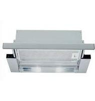
CD53030 - Range hood CONSTRUCTA - Free user manual and instructions
Find the device manual for free CD53030 CONSTRUCTA in PDF.


| Product type | Cooker hood |
| Brand | Constructa |
| Model | CD53030 |
| Dimensions (W x D x H) | Approximately 90 cm x 50 cm x 40 cm |
| Weight | Approximately 12 kg |
| Power supply | 230 V ~ 50 Hz |
| Maximum power | 250 W |
| Maximum air flow | Approximately 600 m³/h |
| Maximum noise level | 65 dB(A) |
| Number of speeds | 3 speeds + intensive |
| Filter type | Washable metal grease filter |
| Charcoal filter (optional) | Recyclable model available as accessory |
| Lighting | 2 LED bulbs (2 x 3 W) |
| Operation | Extraction or recirculation |
| Controls | Push buttons |
| Filter maintenance | Grease filter dishwasher safe |
| Safety | Automatic shut-off in case of overheating |
| Repairability index | 7.5/10 (estimated) |
| Spare parts available | Filters, bulbs, switches |
Frequently Asked Questions - CD53030 CONSTRUCTA
User questions about CD53030 CONSTRUCTA
0 question about this device. Answer the ones you know or ask your own.
Ask a new question about this device
Download the instructions for your Range hood in PDF format for free! Find your manual CD53030 - CONSTRUCTA and take your electronic device back in hand. On this page are published all the documents necessary for the use of your device. CD53030 by CONSTRUCTA.
USER MANUAL CD53030 CONSTRUCTA
[en] Instructions for installation and use 55
Abb. 1
GAS
GAZ
ELEKTRO
ELECTRO

Gerätebeschreibung
natural_image
Architectural detail showing structural details with magnified inset (no text or symbols)natural_image
Illustration of a hand using a tool to interact with a mechanical device, showing a curved arrow indicating rotation (no text or symbols present)Ausbauen:
natural_image
Hand pressing a button on a wooden shelf panel (no text or symbols visible)natural_image
Architectural site plan showing building layout and water features with a black arrow pointing to a specific area (no text or symbols present)natural_image
Illustration of a hand holding a device with a curved panel and screen, no visible text or symbolsnatural_image
Illustration of a hand using a tool to apply material to a component, with an arrow indicating the process (no text or symbols present)natural_image
3D rendering of a mechanical component with a circular housing and mounting base (no text or symbols visible)natural_image
3D rendering of a mechanical assembly with concentric cylindrical components mounted on a base (no text or symbols visible)natural_image
Technical illustration of a mechanical assembly with a magnified inset showing a component detail (no text or symbols present)natural_image
Technical diagram of a ceiling fixture with screw fasteners and mounting holes (no text or labels)natural_image
Illustration of hands holding a tool interacting with a circular mechanical component, no text or symbols presentnatural_image
Architectural diagram showing structural components with magnified views of a grid-patterned structure (no text or symbols)natural_image
Illustration of a hand using a tool to interact with a mechanical device, showing a rotating arrow (no text or symbols present)Demonteren:
natural_image
Hand pressing a corner detail of a wooden shelf with a directional arrow (no text or symbols)natural_image
Aerial view of a large industrial or construction site with a black arrow pointing to a specific area, no visible text or symbols.natural_image
Illustration of a hand holding a small object near a textured surface with a curved pattern (no text or symbols)natural_image
Illustration of a robotic arm operating a mechanical component with a magnified view showing the process (no text or symbols present)natural_image
3D rendering of a mechanical fan component mounted on a base plate (no text or symbols visible)natural_image
3D rendering of a mechanical assembly with layered cylindrical components mounted on a base (no text or symbols visible)natural_image
Technical illustration of a mechanical assembly with a magnified inset showing a pipe connection (no text or symbols present)natural_image
Technical diagram showing installation of a ceiling fixture with screw fasteners and mounting base (no text or symbols)natural_image
Illustration of hands holding a tool and a ruler inside a circular frame, with no visible text or symbols.natural_image
Architectural detail showing structural details with magnified inset (no text or symbols)natural_image
Illustration of a hand inserting a component into a mechanical assembly, showing structural components and motion direction (no text or symbols)Retrait:
natural_image
Hand interacting with a mechanical component, showing a hand pressing a button on a textured surface (no text or symbols visible)natural_image
Architectural site plan showing building layout with a black arrow pointing to a specific area (no text or labels visible)natural_image
Illustration of a hand holding a small circular object, partially covered by a textured surface with no visible text or symbols.natural_image
Illustration of a hand using a tool to sample material in a container, with an arrow indicating process direction (no text or symbols present)natural_image
3D rendering of a mechanical component with a fan-like structure mounted on a base (no text or symbols visible)natural_image
3D rendering of a cylindrical mechanical component mounted on a base plate (no text or symbols visible)natural_image
Technical illustration of a mechanical assembly with a magnified inset showing a component detail (no text or symbols present)natural_image
Technical diagram showing installation of a ceiling fixture with screw fasteners and a structural component (no text or labels)natural_image
Illustration of hands holding a tool and a ruler inside a circular frame, with no visible text or symbols.natural_image
Architectural detail showing structural details with magnified inset (no text or symbols)natural_image
Illustration of a hand holding a tool interacting with a mechanical device, showing internal components and motion arrows (no text or symbols)Smontaggio:
natural_image
Hand pressing a button on a wooden shelf panel (no text or symbols visible)natural_image
Architectural site plan showing building layout with a black arrow pointing to a specific area (no text or labels visible)- Cambiare la lampadina. (lampadina ovale commerciale comune da max. 40 Watt, portalampada E 14).

natural_image
Illustration of a hand holding a small object near a textured surface with a curved panel and circular elements (no text or symbols)natural_image
Illustration of a robotic arm operating a mechanical component with a magnified view showing the process (no text or symbols present)natural_image
3D rendering of a mechanical fan or vent component mounted on a base, with no visible text or symbols.natural_image
3D rendering of a cylindrical mechanical component mounted on a base plate (no text or symbols visible)natural_image
Diagram of a mechanical assembly with a magnified inset showing internal components (no text or symbols)natural_image
Technical diagram of a ceiling structure with screw fasteners and mounting points (no text or labels)natural_image
Illustration of hands holding a ruler and a magnifying glass over a wall, with a screw being inserted (no text or symbols)Operating modes
Exhaust-air mode:
☐ The extractor-hood fan extracts the kitchen vapours and conveys them through the grease filter into the atmosphere.
☐ The grease filter absorbs the solid particles in the kitchen vapours.
☐ The kitchen is kept almost free of grease and odours.
When the extractor hood is operated in exhaust-air mode simultaneously with a different burner which also makes use of the same chimney (such as gas, oil or coal-fired heaters, continuous-flow heaters, hot-water boilers) care must be taken to ensure that there is an adequate supply of fresh air which will be needed by the burner for combustion.
Safe operation is possible provided that the underpressure in the room where the burner is installed does not exceed 4 Pa (0.04 mbar).
Operating modes
This can be achieved if combustion air can flow through non-lockable openings, e.g. in doors, windows and via the air-intake/exhaust-air wall box or by other technical measures, such as reciprocal interlocking, etc.
If the air intake is inadequate, there is a risk of poisoning from combustion gases which are drawn back into the room.
An air-intake/exhaust-air wall box by itself is no guarantee that the limiting value will not be exceeded.
Note: When assessing the overall requirement, the combined ventilation system for the entire household must be taken into consideration. This rule does not apply to the use of cooking appliances, such as hobs and ovens.
Unrestricted operation is possible if the extractor hood is used in recirculating mode – with activated carbon filter.
Circulating-air mode:
☐ An activated carbon filter must be fitted for this operating mode (see Filters and maintenance).
⚠ The complete installation set and replacement filters can be obtained from specialist outlets.
The corresponding accessory numbers can be found at the end of these operating instructions.
☐ The extractor-hood fan extracts the kitchen vapours which are purified in the grease filter and activated carbon filter and then conveyed back into the kitchen.
☐ The grease filter absorbs the grease particles in the kitchen vapours.
☐ The activated carbon filter binds the odorous substances.
⚠️ If no activated carbon filter is installed, it is not possible to bind the odorous substances in the cooking vapours.
Before using for the first time
Important notes:
☐ The Instructions for Use apply to several versions of this appliance. Accordingly, you may find descriptions of individual features that do not apply to your specific appliance.
☐ This extractor hood complies with all relevant safety regulations.
Repairs should be carried out by qualified technicians only.
Improper repairs may put the user at considerable risk.
⚠️ Do not use the appliance if damaged.
⚠ The appliance may be connected to the mains by a qualified technician only.
⚠ The appliance is not intended for use by young children or infirmed persons without supervision.
Young children should be supervised to ensure they do not play with the appliance.
⚠️If the connecting cable for this appliance is damaged, the cable must be replaced by the manufacturer or his customer service or a similarly qualified person in order to prevent serious injury to the user.
⚠ Dispose of packaging materials properly (see Installation instructions).
⚠ This extractor hood is designed for domestic use only.
Light bulbs must always be fitted when the extractor hood is in use.
⚠️ Defective bulbs should be replaced immediately to prevent the remaining bulbs from overloading.
⚠️ Never operate the extractor hood without a grease filter.
⚠️ Overheated fat or oil can easily catch fire. If you are cooking with fat or oil, e.g. chips, etc., never leave the cooker unattended.
⚠️Do not flambé food directly under the extractor hood.
! Risk of grease filter catching fire due to flames.
Before using your appliance for the first time, please read these Instructions for Use carefully. They contain important information concerning your personal safety as well as on use and care of the appliance.
☐ Please retain the operating and installation instructions for a subsequent owner.
⚠ The hotplates must always be covered with a utensil.
⚠️ Restrictions apply to the use of the extractor hood over a solid-fuel burner (coal, wood, etc.). (See Installation instructions).
Gas hobs / Gas cookers
Do not use all the gas hotplates simultaneously for a prolonged period (max. 15 minutes) at maximum thermal load, otherwise there is a risk of burns if the housing surfaces are touched or a risk of damage to the extractor hood. If the extractor hood is situated over a gas hob, operate the hood at maximum setting if three or more gas hotplates are operated simultaneously.
If you encounter a problem
If you have any questions or if a fault occurs, please call Customer Service.
(See list of Customer Service representatives).
When you call, please quote the following:
E-Nr.
FD
Enter the relevant numbers into the box above. The E-Nr. (product no.) and FD (production date) are shown on the nameplate which can be seen inside the extractor hood after the filter frame has been detached.
Operating the extractor hood

Kitchen fumes are best eliminated by:
when you start cooking.
several minutes after you finish cooking.
Switching ON the fan:
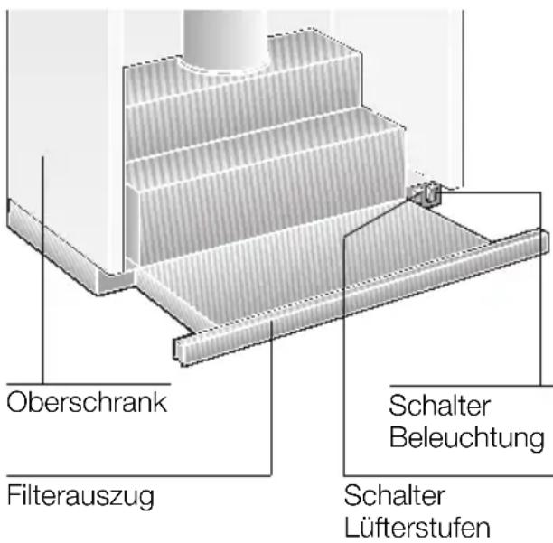
- Pull out the filter drawer by the handle.
☐ The fan is now operating.
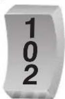
- Select the desired fan setting.
Controls on the various models:

Setting 3
Setting 1
Setting 2

Setting 1

Setting 2

Setting 3
Setting 1
OFF
Setting 2
Switching OFF the fan:
☐ Push in the filter drawer all the way.
Note: If the filter drawer is pulled out again, the fan starts operating at the last selected setting.
Light:
OFF
ON
Note: the light can be used at any time, even if the filter drawer has been pushed in.
Filters and maintenance
Metal-mesh grease filters have been installed to filter grease particles out of the kitchen fumes.
The filter mats are made of incombustible metal.
Attention:
As grease accumulates in the filter, there is an increased risk of the filter catching fire and the extractor hood may malfunction.
Important:
By cleaning the metal grease filters at appropriate intervals, the possibility of them catching fire as a result of a build-up of heat such as occurs when deep-fat frying or roasting is taking place, is reduced.
Cleaning the metal grease filters:
☐ In normal operation (1 to 2 hours daily), the metal grease filter must be cleaned 1 x a month.
☐ The filters can be cleaned in a dish-washer. It is however possible that they will become slightly discoloured.
☐ The filter must be placed loosely, and NOT wedged, in the dishwasher.
Important:
Metal filters that are saturated with grease should not be washed together with other dishes etc.
☐ When cleaning the filters by hand, soak them in hot soapy water first of all. Do not use aggressive, acidic or caustic cleaners.
Then brush the filters clean, rinse them thoroughly and leave the water to drain off.
Removing and installing the filter frames
Removal:
- Pull out the filter drawer all the way.
- Press the detents on the filter frames all the way in the direction of the arrow.

natural_image
Architectural detail showing roof structure with inset magnified view of structural details (no text or symbols)☐ If there are two grease filters, remove the front one first.
- Fold the filter frame down at the side and remove.
Installation:
- Pull out the filter drawer all the way.
- Insert the filter frame at an angle into the holder, fold up and attach by pressing the detent all the way. ☐ If there are two grease filters, first insert the rear filter frame and then the front filter frame (profiled edge) into the filter drawer.
⚠ Ensure that the grease filters are securely positioned on both sides.
Filters and maintenance
Activated carbon filter:
For filtering odours during circulating-air mode.
The activated carbon filter is installed above the grease filter(s) in the extractor hood.
- Remove the grease filter(s) (see Filters and maintenance).
- Insert the two enclosed plastic holders into the right and left sides of the extractor-hood housing and attach each holder with a screw (required only if installing an activated carbon filter for the first time).

natural_image
Illustration of a hand inserting a component into a device with an arrow indicating rotation (no text or symbols present)- Insert the activated carbon filter from below into the extractor-hood housing and lock into position on both sides.
⚠ Ensure that the edge of the activated carbon filter is underneath.
- Re-install the grease filter (see Filters and maintenance).
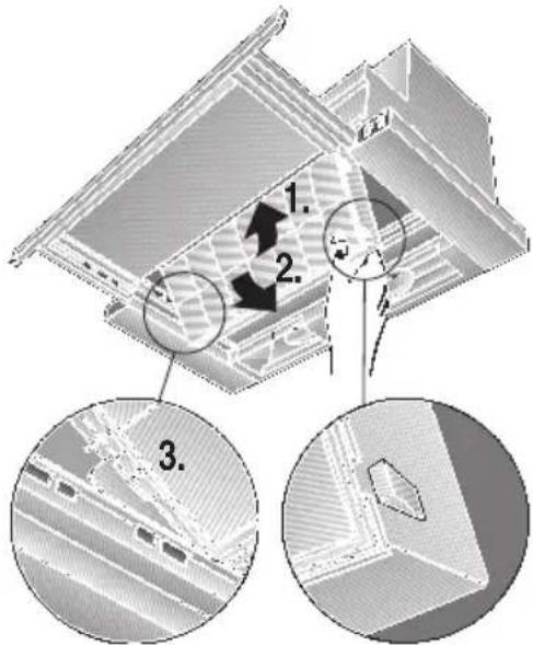
Removal:
The activated carbon filter is removed in reverse sequence.
Press the locking hooks outwards.
Replacing the activated carbon filter:
During normal operation (1 to 2 hours daily), the activated carbon filter should be replaced approx. 1 x year. The activated carbon filter can be obtained from specialist retailers (see Optional accessories).
☐ To ensure the best possible results, use only original filters.
Disposal of the old activated carbon filter:
□ Activated carbon filters do NOT contain any pollutants, i.e. they can be disposed of as household rubbish.
Cleaning and care
For appliances with a glass plate in the pull-out vapour extractor:
☐ The glass plate is easily removed and can be cleaned in a dishwasher.
☐ To remove the lugs, push outwards.

natural_image
Hand pressing a corner detail of a wooden shelf panel (no text or symbols visible)Cleaning and care
Isolate the extractor hood by pulling out the mains plug or switching off the fuse.
⚠ Do not clean the extractor hood with abrasive sponges or with cleaning agents which contain sand, soda, acid or chlorine!
☐ Clean the extractor hood with a hot soap solution or a mild window cleaner.
☐ Do not scrape off dried-on dirt but wipe off with a damp cloth.
☐ When cleaning the grease filters, remove grease deposits from accessible parts of the housing. This prevents the risk of fire and ensures that the extractor hood continues operating at maximum efficiency.
☐ Note: Do not use alcohol (spirit) on plastic surfaces, as dull marks may appear.
Caution: Ensure that the kitchen is adequately ventilated. Avoid naked flames!
⚠ Clean the operating buttons with a mild soapy solution and a soft, damp cloth only. Do not use stainless-steel cleaner to clean the operating buttons.
Stainless steel surfaces:
☐ Use a mild non-abrasive stainless steel cleaner.
☐ Clean the surface in the same direction as it has been ground and polished.
☐ We recommend our stainless steel cleaner no. 461731.
See enclosed service booklet for order address.
Aluminium and plastic surfaces:
☐ Do not use dry cloths.
☐ Use a mild window cleaning agent.
☐ Do not use aggressive, acidic or caustic cleaners.
Observe the warranty regulations in the enclosed service booklet.
Replacing the light bulb
- Switch off the extractor hood and pull out the mains plug or switch off the electricity supply at the fuse box.
- Pull out the filter drawer all the way.
- Pull the lamp cover forwards.

natural_image
Architectural site plan showing building layout with a black arrow pointing to a specific area (no text or symbols present)- Replace the light bulbs. (Standard candle bulbs, max. 40 W, E14 socket).

natural_image
Illustration of a hand holding a small object near a textured surface with a curved structure (no text or symbols)- Re-insert the lamp cover.
- Plug appliance into mains again or switch on at the fuse box.
Important information
⚠️Old appliances are not worthless rubbish. Valuable raw materials can be reclaimed by recycling old appliances. Before disposing of your old appliance, render it unusable.
⚠️You received your new appliance in a protective shipping carton. All packaging materials are environmentally friendly and recyclable. Please contribute to a better environment by disposing of packaging materials in an environmentally-friendly manner.
Please ask your dealer or inquire at your local authority about current means of disposal.
⚠ The extractor hood can be used in exhaust air or circulating air mode.
⚠️Always mount the extractor hood over the centre of the hob.
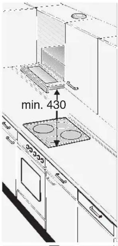
⚠ Minimum distance between electric hob and bottom edge of extractor hood: 430 mm, Fig. 1.
⚠ The extractor hood must not be installed over a solid fuel cooker – a potential fire hazard (e.g. flying sparks) – unless the cooker features a closed, non-removable cover and all national regulations are observed.
⚠ The smaller the gap between the extractor hood and hotplates, the greater the likelihood that droplets will form on the underside of the extractor hood.
Additional information concerning gas cookers:
When installing gas hotplates, comply with the relevant national statutory regulations (e.g. in Germany: Technische Regeln Gasinstallation TRGI).
⚠️Always comply with the currently valid regulations and installation instructions supplied by the gas appliance manufacturer.
⚠️Only one side of the extractor hood may be installed next to a high-sided unit or high wall. Gap at least 50 mm.
⚠ Minimum distance on gas hotplates between the upper edge of the trivet and lower edge of the extractor hood: 650 mm, Fig. 1.
Exhaust-air mode

The exhaust air is discharged upwards through a ventilation shaft or directly through the outside wall into the open.
Exhaust air should neither be directed into a smoke or exhaust flue that is currently used for other purposes, nor into a shaft that is used for ventilating rooms in which stoves or fireplaces are also located.
Exhaust air may be discharged in accordance with official and statutory regulations only (e.g. national building regulations).
Local authority regulations must be observed when discharging air into smoke or exhaust flues that are not otherwise in use.
When the extractor hood is operated in exhaust-air mode simultaneously with a different burner which also makes use of the same chimney (such as gas, oil or coal-fired heaters, continuous-flow heaters, hot-water boilers) care must be taken to ensure that there is an adequate supply of fresh air which will be needed by the burner for combustion.
Safe operation is possible provided that the underpressure in the room where the burner is installed does not exceed 4 Pa (0.04 mbar).
This can be achieved if combustion air can flow through non-lockable openings, e.g. in doors, windows and via the air-intake/exhaust-air wall box or by other technical measures, such as reciprocal interlocking, etc.
If the air intake is inadequate, there is a risk of poisoning from combustion gases which are drawn back into the room.
An air-intake/exhaust-air wall box by itself is no guarantee that the limiting value will not be exceeded.
Note: When assessing the overall requirement, the combined ventilation system for the entire household must be taken into consideration. This rule does not apply to the use of cooking appliances, such as hobs and ovens.
Unrestricted operation is possible if the extractor hood is used in recirculating mode – with activated carbon filter.
For operating in exhaust-air mode, a one-way flap should be mounted inside the extractor hood unless there is already one fitted in the outlet duct or wall ventilation box.
If no one-way flap was enclosed with the hood, it can be obtained from a specialist retailer (see section on optional accessories in the user instructions).
Prior to installation
Installing the one-way flap:
- Cut out the protective grid in the air-pipe connector.
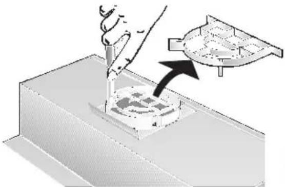
natural_image
Illustration of a hand using a tool to process a mechanical component with an arrow indicating motion (no text or symbols present)- Insert the one-way flap into the bearing apertures on the air-pipe connector.

natural_image
3D rendering of a mechanical fan component mounted on a base, no visible text or symbolsIf the exhaust air is going to be discharged into the open, a telescopic wall box should be fitted into the outside wall.
For optimum extractor hood efficiency:
☐ Short, smooth air exhaust pipe.
☐ As few bends in the pipe as possible.
☐ Diameter of pipe to be as large as possible (ideal is 120 mm) and no tight bends in pipe.
If long, rough exhaust-air pipes, many pipe bends or smaller pipe diameters are used, the air extraction rate will no longer be at an optimum level and there will be an increase in noise.
The manufacturer of the extractor hoods accepts no liability for complaints which can be attributed to the design and layout of the pipework.
☐ Round pipes:
We recommend
Internal diameter at least. 120 mm.
☐ Flact ducts must have an internal cross-section that equates to that of round pipes with a 100/120 mm internal diameter
There should be no sharp bends.
∅ 100 mm approx. 78 cm
∅ 120 mm approx. 113 cm
If pipes have different diameters:
☐ Insert sealing strip.
☐ For exhaust-air mode, ensure that there is an adequate supply of fresh air.
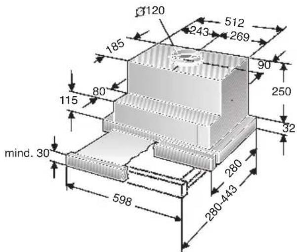
Exhaust air flows upwards:
☐ Cut a hole in the top of the wall cupboard, including a groove for the mains cable.
- Template① lis enclosed -.

Prior to installation
Exhaust flows straight out at the back:
- inside the wall cupboard -.
☐ Cut a hole in the rear panel of the wall cupboard, including a groove for the mains cable.
Connecting the 100 mm exhaust-air pipe:
☐ Cut out the protective grid in the air outlet.
☐ Attach the reducing connector (enclosed or can be obtained from specialist retailers) to the air outlet.
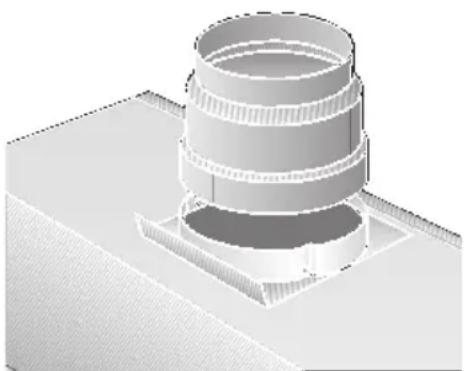
natural_image
3D rendering of a cylindrical mechanical component mounted on a base, with no visible text or symbols.Connecting the 120 mm exhaust-air pipe:
☐ Cut out the protective grid in the air outlet.
Circulating-air mode
☐ With activated carbon filter if exhaust-air mode is not possible.
⚠ The complete installation set can be obtained from specialist outlets. The corresponding accessory numbers can be found at the end of these operating instructions.

Electrical connection
This is what you have to do:
- Connect the green and yellow (Earth) wire to the terminal in the plug marked 'E' or with the symbol (≡), or coloured green or green and yellow.
- Connect the blue (Neutral) wire to the terminal in the plug marked 'N' or coloured black.
- Connect the brown (Live) wire to the terminal marked 'L', or coloured red.
The extractor hood may only be connected to an earthed socket that has been installed according to the relevant regulations. If possible, site the earthed socket directly above the wall cupboard or in its immediate vicinity.
☐ The earthed socket should be connected via its own power circuit.
☐ If the earthed socket is no longer accessible following installation of the extractor hood, ensure that there is a permanently installed disconnector.
If it is necessary to wire the extractor hood directly into the mains:
The extractor hood should only be connected to the electricity supply by a properly qualified electrician.
A separator must be installed in the household circuit. A suitable separator is a switch that has a contact gap of more than 3 mm and interrupts all poles. Such devices include circuit breakers and contactors.
Electrical data:
Are to be found on the name plate inside the appliance after removal of the filter frame.
⚠️Before undertaking any repairs, always disconnect the extractor hood from the electricity supply.
Length of the connecting cable: 1.30 m.
This extractor hood corresponds to EC regulations concerning RF interference suppression.
Preparing the wall cupboard
⚠ Ensure that there is a minimum gap between hob and extractor hood of 650 mm (for gas hobs) or 430 mm (for electric hobs).
This extractor hood has been designed for installation inside a wall cupboard with the following dimensions:
Width: 600 mm
Height: at least 300 mm.
Preparation:
- Remove bottom panel of cupboard – if fitted.
⚠ The stability of the cupboard must be maintained.
- Mark two points – right and left – on the inside of the cupboard where the hood is to be mounted, and start the hole with a gimlet.
Details for drilling:
∅ 2 mm - max. 10 mm deep.
Attention:
☐ Use enclosed template Ⓐ for marking points where hood is to be mounted.
☐ The mounting points shown on the template have been configured in such a way as to allow a 20 mm thick handle to be attached flush with the front edges of the cupboard.
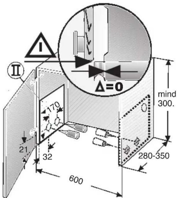
☐ A stop allows the handle (Dimension ) to be positioned further forwards.

If the cupboard depth is greater than 280 mm, the hood can be mounted further back,
... if the light strip under the cupboard units is mounted further back, ... if the handle is more than 20 mm thick.
Position the template ⑪ further back.
Preparing the wall cupboard
- Align and screw on the enclosed mounting rails.
⚠️Note the thickness of the sides of the cupboard (16 mm or 19 mm). dimension X.

⚠️If the interior depth of the cupboard is less than 280 mm, the 250 mm high rear panel must be removed.
Installation inside the wall cupboard
- Remove the filter frames (see Operating Manual).
- If the hinges are no longer accessible when the extractor hood has been installed, align the cupboard doors.
- Lift and push the extractor hood from below into the cupboard until the installation aids on the left and right lock into position.

natural_image
Diagram of a heat exchanger with a magnified inset showing internal components (no text or symbols)- Pull out the filter drawer all the way.
- Attach the extractor hood by screwing in 2 screws on the left and right. Do NOT tighten the screws. Raise the extractor hood.
- Align the extractor hood in the cupboard and tighten the screws.

Installation inside the wall cupboard
-
Feed the mains connection cable through the aperture into the upper cupboard and connect the pipe.
-
Connect to the power supply.
-
If required, shorten the wall cover to the required size (e.g. saw off) and screw to the upper cupboard.

natural_image
Technical diagram of a ceiling structure with screw fasteners and mounting points (no text or labels)Attaching a handle:
☐ A handle must be attached to the filter drawer.
☐ This handle can either be a wooden strip that matches the kitchen cupboards or a the handle that is available as an optional accessory (see section on optional accessories in the user instructions).
- Mark two points on the handle with the enclosed template ③ and make holes with a bradawl.
If the holes are drilled: 2 mm – max. 10 mm deep.
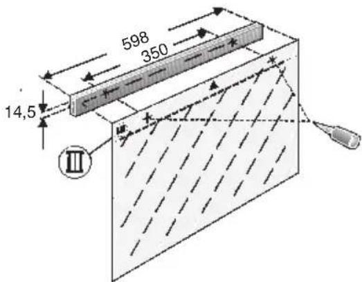
- Align the handle and screw onto the appliance with the two enclosed screws.
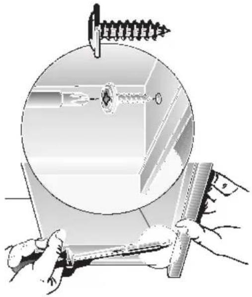
natural_image
Illustration of hands holding a tool and a ruler inside a circular frame, with no visible text or symbols.- Insert the filter frames (see Operating Manual).
Note: The extractor hood housing inside the wall cupboard can be boarded up (e.g. with chipboard).
Please observe the following:
- The shelf must not be rest upon the extractor hood housing.
- The board at the front should not be attached to the housing.
- Provide access for customer service.
Removal:
The extractor hood is removed in reverse sequence.
Note: In circulating-air mode the activated carbon filter and plastic holder must be removed in order to gain access to the mounting screws and installation aids.
Weight in kg:
| Exhaust air Re-circulating air | |
| 9,5 10,5 | |
The manufacturer reserves the right to make design alterations in the interests of technical development.
 |   | CZ5143X5 |
| 2x | ||
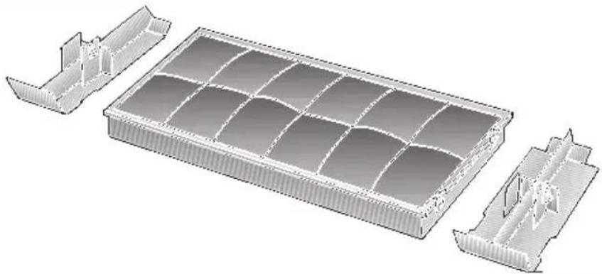 | 296178 | |
 | 086244 | |
 | Metall: CZ5770N0 | |
- Gerätebeschreibung
- Ausbauen:
- Demonteren:
- Retrait:
- Smontaggio:
- Operating modes
- Exhaust-air mode:
- If the air intake is inadequate, there is a risk of poisoning from combustion gases which are drawn back into the room.
- Circulating-air mode:
- Before using for the first time
- Important notes:
- Gas hobs / Gas cookers
- If you encounter a problem
- E-Nr.
- FD
- Operating the extractor hood
- Switching ON the fan:
- Controls on the various models:
- Switching OFF the fan:
- Light:
- Filters and maintenance
- Metal-mesh grease filters have been installed to filter grease particles out of the kitchen fumes.
- Attention:
- Important:
- Cleaning the metal grease filters:
- Removing and installing the filter frames
- Removal:
- Installation:
- Activated carbon filter:
- For filtering odours during circulating-air mode.
- Replacing the activated carbon filter:
- Disposal of the old activated carbon filter:
- Cleaning and care
- For appliances with a glass plate in the pull-out vapour extractor:
- Isolate the extractor hood by pulling out the mains plug or switching off the fuse.
- Stainless steel surfaces:
- Aluminium and plastic surfaces:
- Observe the warranty regulations in the enclosed service booklet.
- Replacing the light bulb
- Important information
- Additional information concerning gas cookers:
- Exhaust air may be discharged in accordance with official and statutory regulations only (e.g. national building regulations).
- Prior to installation
- Installing the one-way flap:
- If pipes have different diameters:
- Exhaust air flows upwards:
- Exhaust flows straight out at the back:
- Connecting the 100 mm exhaust-air pipe:
- Connecting the 120 mm exhaust-air pipe:
- Circulating-air mode
- Electrical connection
- If it is necessary to wire the extractor hood directly into the mains:
- Electrical data:
- Preparing the wall cupboard
- Preparation:
- Installation inside the wall cupboard
- Attaching a handle:
- Please observe the following:
Brand : CONSTRUCTA
Model : CD53030
Category : Range hood