EC 6B - Compressor HITACHI - Free user manual and instructions
Find the device manual for free EC 6B HITACHI in PDF.

| Product Type | Air Compressor |
| Brand | Hitachi |
| Model | EC 6B |
| Power Supply | Single-phase, 115 V - 60 Hz |
| Motor Power | 1 HP (0.75 kW) |
| Rated Current | 7.8 A |
| Tank Capacity | 3.3 gallons (12.5 L) |
| Maximum Pressure | 125 PSI (8.6 bars) |
| Free Air Delivery at 40 PSI | 3.2 CFM (91 L/min) |
| Free Air Delivery at 90 PSI | 2.5 CFM (71 L/min) |
| Free Air Delivery at 100 PSI | 2.4 CFM (68 L/min) |
| Lubrication | Oil (synthetic oil SAE 5W50 or multigrade SAE 10W40) |
| Thermal Protection | Yes, with manual reset |
| Pressure Switch | Yes, AUTO/OFF positions |
| Main Applications | Air supply for a pneumatic nailer or stapler |
| Maintenance - Tank Drain | Every day or every 4 hours of use |
| Maintenance - Intake Filter Cleaning | Every 50 hours or once a month |
| Maintenance - Oil Change | After first 50 hours, then every 300 hours or every 6 months |
| Safety - Grounding | Mandatory, 3-conductor cord |
| Safety - Eye Protection | Wear safety goggles |
Frequently Asked Questions - EC 6B HITACHI
User questions about EC 6B HITACHI
0 question about this device. Answer the ones you know or ask your own.
Ask a new question about this device
Download the instructions for your Compressor in PDF format for free! Find your manual EC 6B - HITACHI and take your electronic device back in hand. On this page are published all the documents necessary for the use of your device. EC 6B by HITACHI.
USER MANUAL EC 6B HITACHI
Improper and unsafe use of this compressor can result in death or serious bodily injury!
This manual contains important information about product safety.
Please read and understand this manual before operating the compressor.
Please keep this manual available for others before they use the compressor.
AVERTISSEMENT
IMPORTANT SAFETY INSTRUCTIONS FOR USE OF THE COMPRESSOR .......4
REPLACEMENT PARTS 5
GROUNDING INSTRUCTIONS 6
EXTENSION CORD 6
SERVICE AND REPAIRS 12
PARTS LIST 34
- TABLE DES MATIÈRES
Français
Page
Page
IINFORMATIONS IMPORTANTES 13
SIGNIFICATION DU VOCABULAIRE DE SIGNALISATION 13
UTILISATION ET ENTRETIEN
NOM DES PIECES 18
FICHE TECHNIQUE 19
ACCESSIONES 19
APPLICATIONS 19
Read and understand all of the operating instructions, safety precautions and warnings in the Instruction Manual before operating or maintaining this compressor.
Most accidents that result from compressor operation and maintenance are caused by the failure to observe basic safety rules or precautions. An accident can often be avoided by recognizing a potentially hazardous situation before it occurs, and by observing appropriate safety procedures.
Basic safety precautions are outlined in the "SAFETY" section of this Instruction Manual and in the sections which contain the operation and maintenance instructions.
Hazards that must be avoided to prevent bodily injury or machine damage are identified by WARNINGS on the compressor and in this Instruction Manual.
Never use this compressor in a manner that has not been specifically recommended by HITACHI, unless you first confirm that the planned use will be safe for you and others.
MEANINGS OF SIGNAL WORDS
WARNING indicates a potentially hazardous situations which, if ignored, could result in serious personal injury.
CAUTION indicates a hazardous situations which, if ignored, could result moderate personal injury, or could cause machine damage.
NOTE emphasizes essential information.
SAFETY
IMPORTANT SAFETY INSTRUCTIONS FOR USE OF THE COMPRESSOR
WARNING: Death or serious bodily injury could result from improper or unsafe use of compressor. To avoid these risks, follow these basic safety instructions:
READ ALL INSTRUCTIONS
Never place your hands, fingers or other body parts near the compressor's moving parts.
2. NEVER OPERATE WITHOUT ALL GUARDS IN PLACE.
Never operate this compressor without all guards or safety features in place and in proper working order. If maintenance or servicing requires the removal of a guard or safety features, be sure to replace the guard or safety features before resuming operation of the compressor.
3. ALWAYS WEAR EYE PROTECTION.
Always wear safety goggles or equivalent eye protection. Compressed air must never be aimed at anyone or any part of the body.
4. PROTECT YOURSELF AGAINST ELECTRIC SHOCK.
Prevent body contact with grounded surfaces such as pipes, radiators, ranges and refrigeration enclosures. Never operate the compressor in damp or wet locations.
5.DISCONNECT THE COMPRESSOR.
Always disconnect the compressor from the power source and remove the compressed air from the air tank before servicing, inspecting, maintaining, cleaning, replacing or checking any parts.
6. AVOID UNINTENTIONAL STARTING.
Do not carry the compressor while it is connected to its power source or when the air tank is filled with compressed air. Be sure the knob of the pressure switch in the "OFF" position before connecting the compressor to its power source.
7. STORE COMPRESSOR PROPERLY
When not in use, the compressor should be stored in a dry place. Keep out of reach of children. Lock-out the storage area.
8. KEEP WORK AREA CLEAN.
Cluttered areas invite injuries. Clear all work areas of unnecessary tools, debris, furniture, etc.
9. CONSIDER WORK AREA ENVIRONMENT
Don't expose compressor to rain. Don't use compressor in damp or wet locations. Keep work area well lit and well ventilated.
Don't use compressor in the presence of flammable liquids or gases.
Compressor produces sparks during operation. Never use compressor in sites containing lacquer, paint, benzine, thinner, gasoline, gases, adhesive agents, and other materials which are combustible or explosive.
10. KEEP CHILDREN AWAY.
Do not let visitors contact compressor extension cord. All visitors should be kept safely away from work area.
11. DRESS PROPERLY.
Do not wear loose clothing or jewelry. They can be caught in moving parts.
Wear protective hair covering to contain long hair.
12. DON'T ABUSE CORD.
Never yank it to disconnect from receptacle. Keep cord from heat, oil and sharp edges.
13. MAINTAIN COMPRESSOR WITH CARE.
Follow instructions for lubricating. Inspect cords periodically and if damaged, have repaired by authorized service center. Inspect extension cords periodically and replace if damaged.
14. OUTDOOR USE EXTENSION CORDS.
When compressor in used outdoors, use only extension cords intended for use outdoors and so marked.
15. STAY ALERT.
Watch what you are doing. Use common sense. Do not operate compressor when you are tired. Compressor should never be used by you if you are under the influence of alcohol, drugs or medication that makes you drowsy.
16. CHECK DAMAGED PARTS AND AIR LEAK.
Before further use of the compressor, a guard or other part is damaged should be carefully checked to determine that it will operate properly and perform its intended function. Check for alignment of moving parts, binding of moving parts, breakage of parts, mounting, air leak, and any other conditions that may affect its operation.
A guard or other part that is damaged should be properly repaired or replaced by an authorized service center unless otherwise indicated elsewhere in this Instruction Manual.
Have defective pressure switches replaced by authorized service center.
Do not use compressor if switch does not turn it on and off.
17. NEVER USE COMPRESSOR FOR APPLICATIONS OTHER THAN THOSE SPECIFIED.
Never use compressor for applications other than those specified in the Instruction Manual.
18. HANDLE COMPRESSOR CORRECTLY.
Operate the compressor according to the instructions provided herein. Never allow the compressor to be operated by children, individuals unfamiliar with its operation or unauthorized personnel.
19. KEEP ALL SCREWS, BOLTS AND COVERS TIGHTLY IN PLACE.
Keep all screws, bolts, and covers tightly mounted. Check their conditions periodically.
20. KEEP MOTOR AIR VENT CLEAN.
The motor air vent must be kept clean so that air can freely flow at all times. Check for dust build-up frequently.
21. OPERATE COMPRESSOR AT THE RATED VOLTAGE.
Operate the compressor at voltages specified on their nameplates.
If using the compressor at a higher voltage than the rated voltage, it will result in abnormally fast motor revolution and may damage the unit and burn out the motor.
22. NEVER USE A COMPRESSOR WHICH IS DEFECTIVE OR OPERATING ABNORMALLY.
If the compressor appears to be operating unusually, making strange noises, or otherwise appears defective, stop using it immediately and arrange for repairs by a Hitachi authorized service center.
23. DO NOT WIPE PLASTIC PARTS WITH SOLVENT.
Solvents such as gasoline, thinner, benzine, carbon tetrachloride, and alcohol may damage and crack plastic parts. Do not wipe them with such solvents.
Wipe plastic parts with a soft cloth lightly dampened with soapy water and dry thoroughly.
24. USE ONLY GENUINE HITACHI REPLACEMENT PARTS.
Replacement parts not manufactured by Hitachi may void your warranty and can lead to malfunction and resulting injuries. Genuine Hitachi parts are available from your dealer.
25. DO NOT MODIFY THE COMPRESSOR.
Do not modify the compressor. Always contact the Hitachi authorized service center any repairs. Unauthorized modification may not only impair the compressor performance but may also result in accident or injury to repair personnel who do not have the required knowledge and technical expertise to perform the repair operations correctly.
26. TURN OFF THE PRESSURE SWITCH WHEN THE COMPRESSOR IS NOT USED.
When the compressor is not used, turn the knob of the pressure switch OFF, disconnect it from the power source and open the drain cock to discharge the compressed air from the air tank.
To reduce the risk of burns, do not touch tubes, heads, cylinder and motors.
28. DO NOT DIRECT AIR STREAM AT BODY.
Risk of injury, do not direct air stream at persons or animals.
29. DRAIN TANK.
Drain tank daily or after 4 hours of use. Open drain fitting and tilt compressor to empty accumulated water.
30. DO NOT STOP COMPRESSOR BY PULLING OUT THE PLUG.
Use the "AUTO/OFF" knob of pressure switch.
31. USE ONLY RECOMMENDED AIR HANDLING PARTS ACCEPTABLE FOR PRESSURE NOT LESS THAN 125 PSI (8.6 BAR)
Risk of bursting. Use only recommended air handling parts acceptable for pressures not less than 125 psi (8.6 bar).
REPLACEMENT PARTS
When servicing use only identical replacement parts.
Repairs should be conducted only by a Hitachi authorized service center.
SAFETY - Continued
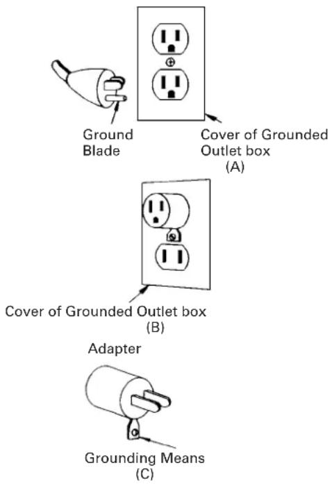
GROUNDING INSTRUCTIONS
This compressor should be grounded while in use to protect the operator from electric shock. The compressor is equipped with a three-conductor cord and three-prong grounding type plug to fit the proper grounding type receptacle. The green (or green and yellow) conductor in the cord is the grounding wire. Never connect the green (or green and yellow) wire to a live terminal. If your unit is for use on less than 150 volts, it has a plug that looks like that shown in sketch (A) in Figure on the right. An adapter, see sketches (B) and (C), is available for connecting sketch (A) type plugs to two-prong receptacles. The green-colored rigid ear, lug, or the like extending from the adapter must be connected to a permanent ground, such as a properly grounded outlet box.
Note: The grounding adaptor, sketch (C), is prohibited in Canada by Canadian Electrical Code Part 1. Therefore, the instructions for its use are not applicable in Canada.
We recommend that you never disassemble the compressor or try to do any rewiring in the electrical system. Any repairs should be performed only by HITACHI Service Centers or other qualified service organizations. Should you be determined to make a repair yourself, remember that the green colored wire is the "grounding" wire. Never connect this green wire to a "live" terminal. If you replace the plug on the power cord, be sure to connect the green wire only to the grounding (longest) prong on a 3-prong plug.
If in doubt, call a qualified electrician and have the receptacle checked for ground.
EXTENSION CORD
Use only three-wire extension cords that have three-prong grounding-type plugs and three-pole receptacles that accept the compressor's plug. Replace or repair damaged cord.
Make sure your extension cord is in good condition. When using an extension cord, be sure to use one heavy enough to carry the current your product will draw. An undersized cord will cause a drop in line voltage resulting in loss of power and overheating. Table shows the correct size to use depending on cord length and name plate ampere rating. If in doubt, use the next heavier gage. The smaller the gage number, the heavier the cord.
MINIMUM GAGE FOR CORD SETS
| Total Length of Cord in Feet (Meter) | |
| 0 - 25 26 - 50 51 - 100 101 - 150 | |
| (0 - 7.6) (7.9 - 15.2) (15.5 - 30.5) (30.8 - 45.7) | |
| Ampere Rating AWG | |
| More Not More | |
| Than Than | |
| 0 - 6 18 16 16 14 | |
| 6 - 10 18 16 14 12 | |
| 10 - 12 16 16 14 12 | |
| 12 - 16 14 12 Not Recommended |
WARNING: Avoid electrical shock hazard. Never use this compressor with a damaged or frayed electrical cord or extension cord. Inspect all electrical cords regularly. Never use in or near water or in any environment where electric shock is possible.
SAVE THESE INSTRUCTIONS AND
MAKE THEM AVAILABLE TO OTHER USERS OF THIS TOOL!
The information contained in this Instruction Manual is designed to assist you in the safe operation and maintenance of the compressor.
Some illustrations in this Instruction Manual may show details or attachments that differ from those on your own compressor.
NAME OF PARTS
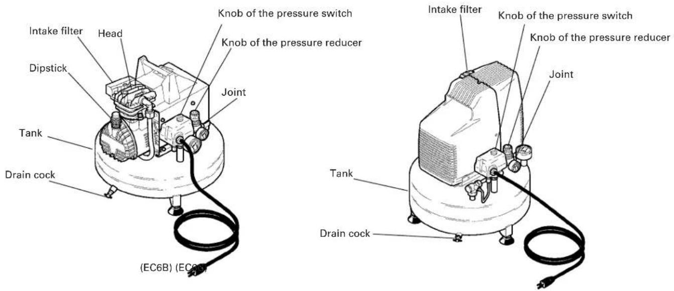
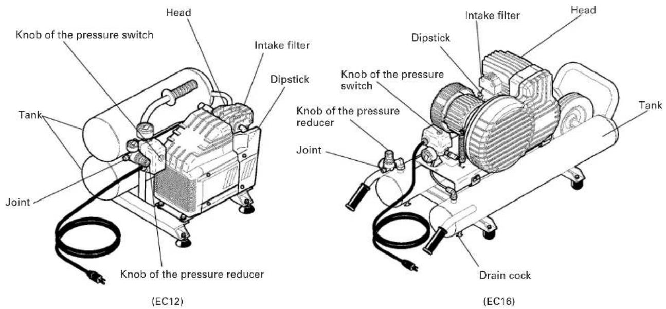
Fig. 1
SPECIFICATIONS
| Model EC6B EC6C EC12 EC16 | |||||
| Motor Single-Phase, Induction | Motor | ||||
| Power Source Single-Phase, 1 | 15V AC 60Hz | ||||
| Input | 1 HP 1 HP 2 HP (0.75 KW) | 2 1/2 HP KW) (1.49 KW) | (1.87 KW) | ||
| Current 7.8A 10.05A 13.5A 13.5A | |||||
| Tank Capacity | 3.3 gal. 3.3 gal. (12.5 ltr) | 4 gal. 5 gal. (12.5 ltr) | (15.1 ltr) | (18.9 ltr) | |
| Maximum Pressure | 125 PSI (8.6 bar) | 125 PSI (8.6 bar) | 125 PSI (8.6 bar) | 145 PSI (10.0 bar) | |
| Free Air Delivery | at 40 PSI (2.8 bar) | 3.2 CFM (91 ltr/min) | 3.0 CFM (85 ltr/min) | 4.2 CFM (119 ltr/min) | 4.9 CFM (130 ltr/min) |
| at 90 PSI (6.2 bar) | 2.5 CFM (71ltr/min) | 2.4 CFM (68 ltr/min) | 4.1 CFM (116 ltr/min) | 4.8 CFM (136 ltr/min) | |
| at 100 PSI (6.9 bar) | 2.4 CFM (68 ltr/min) | 2.4 CFM (68 ltr/min) | 3.6 CFM (102 ltr/min) | 4.7 CFM (133 ltr/min) | |
| Lubrication | Oil Oil-less | Oil | Oil | ||
ACCESSIONS
WARNING:
- Accessories other than those shown below can lead to malfunction and resulting injuries.
STANDARD ACCESSORIES
| EC6B EC12 | Dipstick 1 |
| EC16 | Dipstick 1 |
| EC6C No accessories | |
APPLICATIONS
Air source of the pneumatic nailer and stapler.
PRIOR TO OPERATION
1. Power source
Ensure that the power source to be utilized conforms to the power source requirements specified on the product nameplate.
2. Power switch
Ensure that the knob of the pressure switch is in the "OFF" position. If the plug is connected to a receptacle while the knob is in the "AUTO" position, the compressor will start operating immediately and can cause serious injury.
3. Extension cord
When the work area is far away from the power source, use an extension cord of sufficient thickness and rated capacity (refer page 6). The extension cord should be kept as short as practicable.
WARNING:Damaged cord must be replaced or repaired.
4. Confirm the power receptacle
If the power receptacle only loosely accepts the plug, the receptacle must be repaired. Contact the nearest electric store for repair service.
If such a faulty receptacle is used, may cause overheating, resulting in a serious hazard.
5. Dipstick insertion and oil level check (If your compressor is EC6C this step is not necessary.)
Use a screwdriver or similar tool to remove the plastic cap on the lower part of the cylinder (Fig. 2).
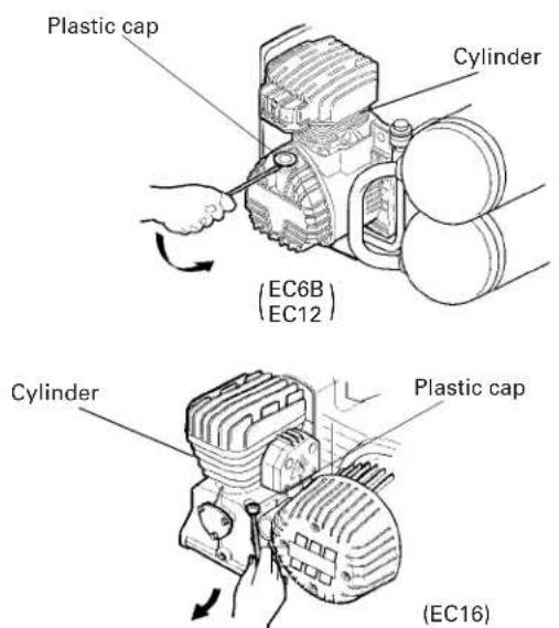
Fig. 2
Insert the accessory dipstick all the way to the bottom. Remove the dipstick and make sure the oil level is within the range of the dipstick notches (Fig. 3).
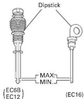
Fig. 3
When the oil volume is insufficient, refer to the section "Oil change-oil topping off" on page 12 for a description of how to supply the oil.
6. Air coupler installation
Screw in the air coupler to the joint (Refer to Fig. 1 and Fig. 4.). The screw size of the joint is 3/8" . Use an air coupler which has the same screw size.
OPERATION
1. Start up
Insert the plug into the receptacle and start the compressor by turning the knob of the pressure switch, to "AUTO". (Refer to Fig. 1 and Fig. 4).
WARNING: Do not stop or start the compressor
by use of the plug. Always use "AUTO/OFF" knob located on the pressure switch.
The operation of the compressor is automatic and is controlled by the pressure switch which stops it when the pressure in the air-tank reaches the maximum level and restart it when the air pressure drops during use to the restart level.
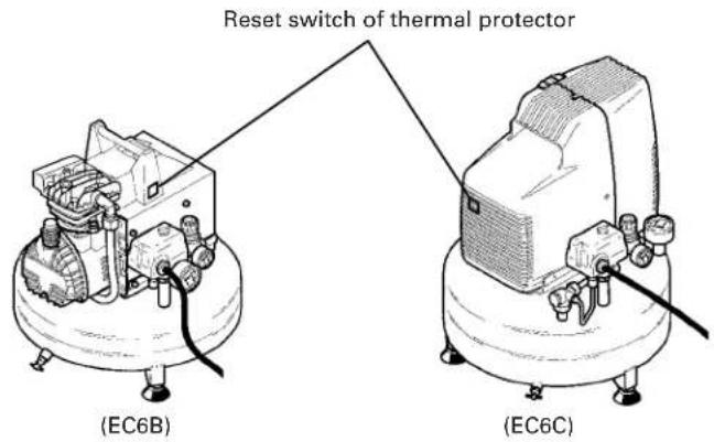
The motor of the compressor is fitted with a thermal protection inside-the wrap, which stops the compressor when the temperature is too high. Should this be tripped, the compressor will restart automatically after 15-20 minutes.
2. Adjustment of working pressure
Unlock the knob of the pressure reducer pulling it up, adjust the pressure to the required level by turning the knob clockwise to increase and counterclockwise to decrease.
A pressure gauge is provided to know when the required pressure is reached, lock the knob by pushing it down firmly (Fig. 4).
WARNING: Check the manufacturer's maximum pressure rating for nailers, staplers and accessories. Compressor outlet pressure must be regulated so as to never exceed the maximum pressure rating of the nailers, staplers and accessories.
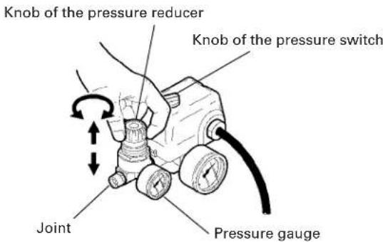
Fig. 4
3.Shutdown
(1) Turn the knob of the pressure switch to "OFF". (Fig. 1)
(2) Unplug the plug from power source.
(3) Open the drain cock located at the lower part of the tank (Fig. 5).
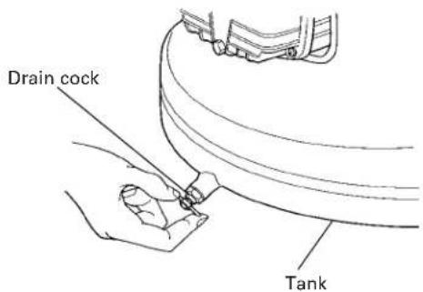
Fig. 5
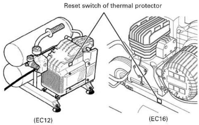
Fig. 6
4. About the thermal protector
This item is not necessary if your compressor is not equipped with the thermal protector reset switch shown in Fig. 6.
The thermal protector operates to stop the motor when a problem such as a motor overload, etc., occurs. If the motor should stop during operation, proceed as follows.
(1) Turn the pressure switch knob to the OFF position (Fig. 1) and disconnect the plug from the receptacle.
(2) If the extension cord does not conform to the specifications given on page 6, replace with an extension cord such as that shown on page 6. If the capacity of the power supply is insufficient, increase the power supply capacity to remove the cause of a flow of excessive current (over-current).
(3) Wait approximately 5 minutes, then press the reset switch of the thermal protector (Fig. 6).
(4) Start up. If the motor still stops during operation, please contact the service center.
MAINTENANCE
WARNING: Disconnect the compressor from the power source and remove the compressed air from the air tank before performing the maintenance operations.
1. Cleaning the intake filter
Remove the intake filter (Refer to Fig. 1.) every 50 hours or once a week and clean the inside of the intake filter and the filter element with compressed air. (Fig. 7) Use a phillips screwdriver to disassemble intake filter models EC6B, EC6C and EC12. Use an allen wrench to disassemble model EC16.
WARNING: Never clean filter element with a flammable liquid or solvent.
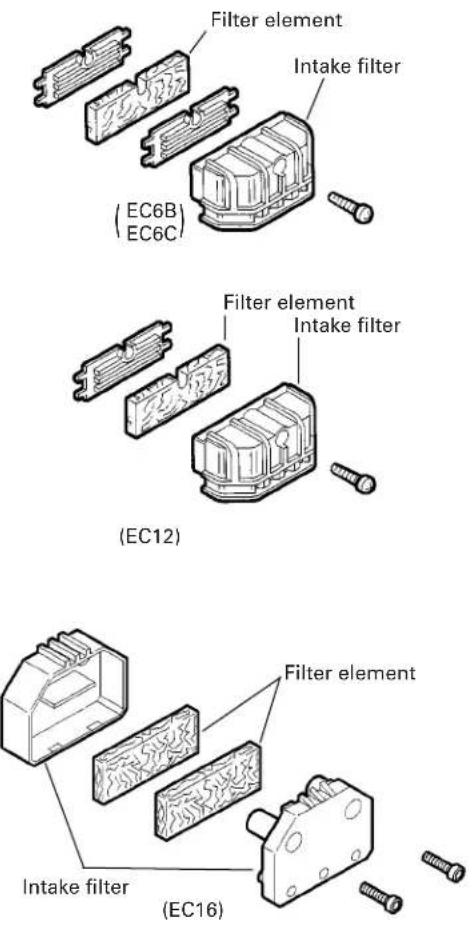
Fig. 7
NOTE:
Replace the filter element when it becomes dirty.
2. Draining tank
Drain tank daily or after 4 hours of use. Open drain fitting and tilt compressor to empty accumulated water. (Fig. 5).
3. Oil change-oil topping off
(Only for EC6B, EC12, EC16)
(1) Within the first 50 hours of operation, completely replace the oil of the pumping element. Unfasten the oil drain cap on the casing cover, drain all the oil, and screw the cap back on (Fig. 8).
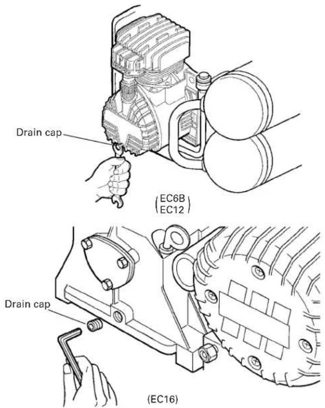
Fig. 8
Pour oil into the hole of the dipstick. To the level indicated on the dipstick (Fig. 3). For oil replacement, follow the table below.
OIL TYPE
SAE 5W50 SYNTHETIC OIL (-20^ + 120^) For both summer and winter use
SAE 10W40 MULTI-GRADED OIL (+50^ + 120^) For warm weather use only
(2) Check the oil level of the pumping element every 50 hours or once a week.
(3) Change the oil every 300 working hours or every 6 months.
SERVICE AND REPAIRS
All quality compressors will eventually require servicing or replacement of parts because of wear from normal use. To assure that only authorized replacement parts will be used, all service and repairs must be performed by a HITACHI AUTHORIZATION SERVICE CENTER, ONLY.
NOTE:
Specifications are subject to change without any obligation on the part of the HITACHI.
INFORMATIONS IMPORTANTES
ACCESSIONS STANDARDS
Parts are subject to change without any obligation on the part of the HITACHI due to improvements.
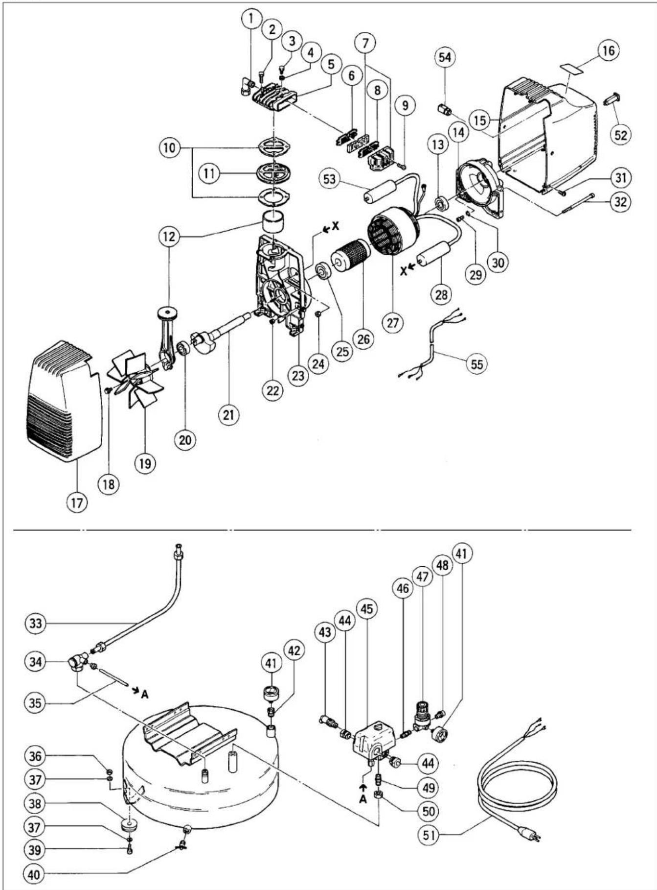
EC6C
EC6C
| Item Code Code No. Reference Part Name Q'ty No. No. (OLD) No. | ||||
| 1 881-455 Joint | 1 160518 7084080000 | |||
| 2 881-392 Screw | 4 160059 7011880000 | |||
| 3 881-415 Screw | 1 160073 7014300000 | |||
| 4 881-414 Washer | 1 160025 7030780000 | |||
| 5 881-456 Head | 1 160122 7570550000 | |||
| 6 881-453 Filter plate | 1 160300 7458340000 | |||
| 7 881-413 Intake filter | 1 160304 4085110000 | |||
| 8 881-452 Filter plate | 1 160301 7458680000 | |||
| 9 881-412 Screw | 1 160067 7012120000 | |||
| 10 881-393 Set of gasket | 1 160109 4082610000 | |||
| 11 881-394 Monoplate | 1 160404 4200030000 | |||
| 12 881-396 | Conrod - Cylinder kit | 1 160142 4190 | 270000 | |
| 13 881-478 Ball bearing | 1 160201 7060010000 | |||
| 14 881-409 Cover | 1 160252 7640100000 | |||
| 15 881-411 Motor housing | 1 160323 7150580000 | |||
| 16 | —— Nameplate | 1 | —— | —— |
| 17 881-398 Compressor housing | 1 160322 7150590000 | |||
| 18 881-399 Screw | 1 160050 7011040000 | |||
| 19 881-397 Fan | 1 160290 4085080000 | |||
| 20 881-395 Ball bearing | 1 160200 4085070000 | |||
| 21 881-400 Crank shaft | 1 160272 5040700008 | |||
| 22 881-401 Nut | 2 160005 7021010000 | |||
| 23 881-402 Carter | 1 160222 7670040000 | |||
| 24 881-403 Nut for capacitor | 1 160003 7020070000 | |||
| 25 881-404 Ball bearing | 1 160204 7060280000 | |||
| 26 881-405 Rotor | 1 160331 5090040008 | |||
| 27 | 881-406 Stator (For U.S.A) | 1 160181 401225 | 0000 | |
| 881-422 Stator (For CANADA) | 1 4012000000 | |||
| 28 | 881-407 Capacitor (For U.S.A) | 1 160171 7310 | 360000 | |
| 881-515 Capacitor (For CANADA) | 1 7310430000 | |||
| 29 881-484 Screw | 1 160063 7012070000 | |||
| 30 881-408 Toothed washer | 1 160026 7031020000 | |||
| 31 881-410 Screw | 4 160071 7012290000 | |||
| 32 881-480 Tension rod | 2 160352 7018010000 | |||
| 33 881-416 Infeed tube | 1 160508 7235780000 | |||
| 34 881-494 Non return valve | 1 160527 7190040000 | |||
| 35 881-496 Tube | 1 7230010000 | —— | ||
| 36 881-418 Nut | 4 160002 7020060000 | |||
| 37 881-419 Washer | 8 160021 7030020000 | |||
| 38 881-577 Rubber | 4 160542 7360140000 | |||
| 39 881-399 Screw | 4 160050 7011040000 | |||
| 40 881-498 Discharge tap | 1 160503 7130280000 | |||
| 41 881-508 Pressure gauge | 2 160533 7110010000 | |||
| 42 881-421 Joint | 1 160524 7085800000 | |||
| 43 881-493 Safety valve | 1 160546 7192270000 | |||
| 44 881-507 Stretch eliminator | 2 160549 7501100000 | |||
| 45 881-512 Pressure switch | 1 160537 7250300000 | |||
| 46 881-511 Joint | 1 160513 7081090000 | |||
| 47 881-510 Pressure reducer | 1 160536 7100120000 | |||
| Item Code Code No. Reference Part Name Q'ty No. (OLD) No. | |||
| 48 881-509 Joint | 1 160523 7085790000 | ||
| 49 881-505 Joint | 1 160514 7081140000 | ||
| 50 881-504 Blocking nut 1 160004 70230 | 40000 | ||
| 51 881-503 Infeed cable 1 160502 73286 | 20000 | ||
| 52 881-423 | Thermal Protector (For CANADA) | 1 74 | 10470000 |
| 53 881-424 | Capacitor (For CANADA) | 1 73 | 1010000 |
| 54 881-517 | Stretch Eliminator (For CANADA) | 1 75 | 1050000 |
| 55 881-518 | Electric Cable (For CANADA) | 1 73 | 29950000 |
Parts are subject to change without any obligation on the part of the HITACHI due to improvements.
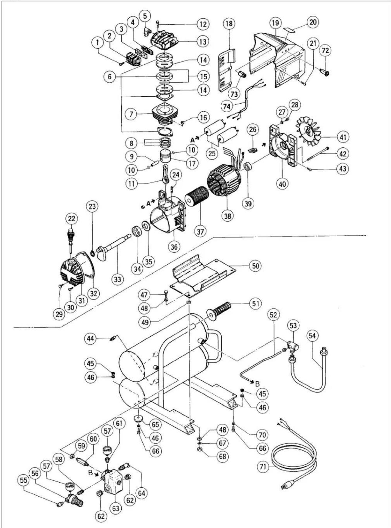
EC12
EC12
Parts are subject to change without any obligation on the part of the HITACHI due to improvements.
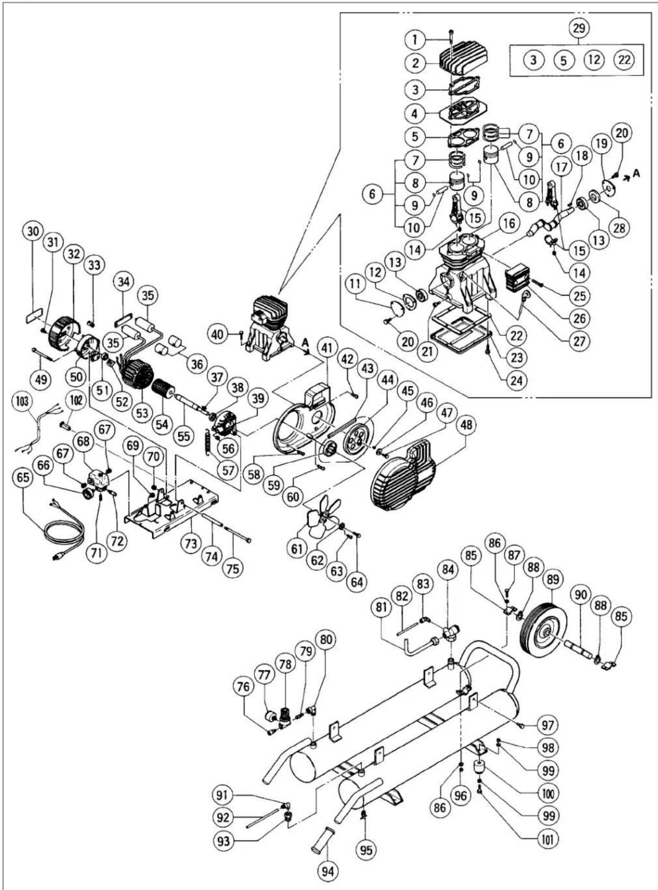
EC16
EC16
| Item Code Code No. (OLD) No. | No. Reference Part Name O'ty | ||||
| 1 | 881-610 | Screw M8×40 | 6 | 160075 | 7010070000 |
| 2 | 881-611 Head | 1 1601 | 21 757007 | 0000 | |
| 3 | 881-612 Gasket | 1 1601 | 02 707900 | 0000 | |
| 4 | 881-613 Valve plate | 1 | 160130 | 4231000000 | |
| 5 | 881-614 Gasket | 1 1601 | 03 707901 | 0000 | |
| 6 | 881-619 Piston group (include 7-10) | 2 1601 | 05 4291 | 030000 | |
| 7 | 881-615 Piston rings | 2 | 160158 | 4080060000 | |
| 8 | 881-616 Piston 2 160152 7220050000 | ||||
| 9 | 881-618 Ring | 4 1604 | 10 704103 | 0000 | |
| 10 881-617 Piston pin | 2 160156 | 7050030000 | |||
| 11 881-624 Cover | 1 160254 | 7650060000 | |||
| 12 881-623 Gasket | 1 160105 | 7079030000 | |||
| 13 881-622 Ball bearing 6204 | 2 160205 | 7060200000 | |||
| 14 881-401 Nut 4 | 160005 7021010000 | ||||
| 15 881-620 Con rod | 2 160143 | 4 190160008 | |||
| 16 881-621 Carter | 1 160220 4240010008 | ||||
| 17 881-633 Crankshaft | 1 160273 | 5041000008 | |||
| 18 881-634 Key | 1 160403 | 7051500000 | |||
| 19 881-636 Cover | 1 160253 | 7650050000 | |||
| 20 | 881-625 Screw M6×15 | 6 | 160077 | 7011920000 | |
| 21 881-626 Plug | 1 160532 | 7098030000 | |||
| 22 881-629 Gasket | 1 160104 | 7079020000 | |||
| 23 881-628 Carter cover | 1 160224 | 7650040000 | |||
| 24 881-627 | Screw M5×15 | 8 160076 7011 | 440000 | ||
| 25 | 881-631 Screw M8×20 | 2 | 160074 | 7010050000 | |
| 26 881-632 Intake filter | 1 160305 | 4250060000 | |||
| 27 881-630 Dipstick | 1 160529 | 7181080000 | |||
| 28 881-635 Smin ring | 1 160411 | 7071100000 | |||
| 29 881-637 | Set of gasket (include 3,5,12,22) | 1 160108 4082 | 510000 | ||
| 30 | —— Nameplate | 1 | —— | —— | |
| 31 881-484 Screw | 4 160063 7012070000 | ||||
| 32 881-641 Conyer | 1 160402 | 7151130000 | |||
| 33 881-640 Stretch eliminator | 1 160548 | 7501050000 | |||
| 34 881-639 Plate | 1 160405 | 7458900000 | |||
| 35 | 881-488 Capacitor (For U.S.A) | 2 160170 7310 | 140000 | ||
| 881-515 Capacitor (For CANADA) | 2 | —— | 7310430000 | ||
| 36 881-638 Capacitor shroud | 2 160172 | 7311000000 | |||
| 37 881-669 Tab | 1 160350 | 7051240000 | |||
| 38 881-478 Ball bearing | 1 160201 | 7060010000 | |||
| 39 881-668 Drilled cover | 1 160255 | 7640070000 | |||
| 40 881-670 Screw | 4 160069 7012200000 | ||||
| 41 881-667 Housing support | 1 160414 | 7151070000 | |||
| 42 881-666 Screw | 1 160070 7012240000 | ||||
| 43 881-665 Belt | 1 160400 | 7370600000 | |||
| 44 881-664 Pulley | 1 160407 7409310000 | ||||
| 45 881-634 Key | 1 160403 | 7051500000 | |||
| 46 881-663 Washer | 1 160024 | 7030270000 | |||
| 47 881-571 Screw | 1 160052 7011100000 | ||||
| 48 881-659 Housing cover | 1 160256 | 7151060000 | |||
| 49 881-642 Tension rod | 2 160351 | 7015140000 | |||
| 50 881-643 Cover | 1 160251 | 7640080000 | |||
| 51 881-478 Ball bearing | 1 160201 | 7060010000 | |||
| 52 881-487 Chock | 1 160401 7500030000 | ||||
| 53 | 881-644 Motor casing (For U.S.A) | 1 160182 7012 | 330000 | ||
| 881-686 Motor casing (For CANADA) | 1 | —— | 4012650000 | ||
| Item Code Code No. Reference Part Name Q'ty No. (OLD) No. | |||
| 54 881-645 Rotor | 1 160333 5090300000 | ||
| 55 881-646 Shaft | 1 160413 7580150000 | ||
| 56 881-418 Nut 2 | 160002 7020020000 | ||
| 57 881-647 Spring | 1 160090 7160060000 | ||
| 58 881-660 Screw | 2 160065 7012090000 | ||
| 59 881-662 Pulley | 1 160408 7409320000 | ||
| 60 881-661 Screw | 2 160068 7012130000 | ||
| 61 881-656 Fan 1 | 160293 7200170000 | ||
| 62 881-658 Washer | 1 160027 7038080000 | ||
| 63 881-492 Screw | 2 160062 7012060000 | ||
| 64 881-657 Screw | 1 160056 7011420000 | ||
| 65 881-503 Infeed cable | 1 160502 7328620000 | ||
| 66 881-650 Pressure gauge | 1 160535 7110210000 | ||
| 67 881-507 Stretch eliminator | 2 160549 7501100000 | ||
| 68 881-575 Pressure switch | 1 160538 7250510000 | ||
| 69 881-649 Plug | 1 160531 7090090000 | ||
| 70 881-648 Selflocking nut | 1 160006 7021050000 | ||
| 71 881-651 Quick coupling | 1 160539 7084220000 | ||
| 72 881-652 Safety valve | 1 160547 7192170000 | ||
| 73 881-653 Base | 1 160500 5011240008 | ||
| 74 881-654 Bushing | 1 160091 7230060000 | ||
| 75 881-655 Tension rod | 1 160353 7015290000 | ||
| 76 881-509 Joint | 1 160523 7085790000 | ||
| 77 881-508 Pressure gauge | 1 160533 7110010000 | ||
| 78 881-510 Pressure reducer | 1 160536 7100120000 | ||
| 79 881-678 Joint | 1 160520 7085170000 | ||
| 80 881-677 Joint | 1 160512 7080010000 | ||
| 81 881-676 Infeed tube | 1 160510 7235540000 | ||
| 82 881-496 Tube | 1 | -7230010000 | |
| 83 881-495 Joint | 1 160515 7082680000 | ||
| 84 881-674 Non return valve | 1 160526 7190010000 | ||
| 85 881-671 Fixing bracket | 2 160502 7498090000 | ||
| 86 881-419 Washer | 8 160021 7030020000 | ||
| 87 881-399 Screw | 4 160050 7011040000 | ||
| 88 881-468 Seeger | 2 160540 7040040000 | ||
| 89 881-673 Wheel | 1 160552 7260080000 | ||
| 90 881-672 Wheel pin | 1 160553 7332010000 | ||
| 91 881-680 Joint | 1 160519 7084240000 | ||
| 92 881-496 Tube | 1 | -7230010000 | |
| 93 881-681 Joint | 1 160522 7085190000 | ||
| 94 881-682 Handle | 2 160504 7280030000 | ||
| 95 881-498 Discharge tap | 2 160503 7130280000 | ||
| 96 881-418 Nut 4 | 160002 7020060000 | ||
| 97 881-685 Screw | 4 160055 7011390000 | ||
| 98 881-401 Nut 4 | 160005 7021010000 | ||
| 99 881-573 Washer | 8 160023 7030190000 | ||
| 100 | 881-684 Rubber | 4 160541 7360990000 | |
| 101 | 881-683 Screw | 4 160051 7011050000 | |
| 102 | 881-588 Thermal Protector (For CANADA) | 1 | -7410690000 |
| 103 | 881-518 Electric Cable (For CANADA) | 1 | -7329950000 |
Parts are subject to change without any obligation on the part of the HITACHI due to improvements.
For USA, distributed by
Hitachi Koki U.S.A., Ltd.
3950 Steve Reynolds Boulevard,
Norcross, GA 30093
For Canada, distributed by
Hitachi Koki Canada Co.
6395 Kestrel Road,
Mississauga, Ontario L5T 1Z5
Hitachi Koki Co., Ltd.
Nippon Bldg., 6-2, Ohtemachi 2-chome,
Chiyoda-ku, Tokyo 100-0004, Japan
810
Code No.C99078263
Printed in Italy