
EC 119 - Compressor HITACHI - Free user manual and instructions
Find the device manual for free EC 119 HITACHI in PDF.


| Brand | Hitachi |
| Model | EC 119 |
| Product Type | Air Compressor |
| Motor | Single-Phase Induction Motor |
| Power Supply | 120 V, 60 Hz, Single-Phase |
| Output Power | 2 HP (1.5 kW) |
| Rated Current | 15.0 A |
| Tank Capacity | 4 gal (15.1 L) |
| Maximum Pressure | 125 PSI (8.6 bar) |
| Air Flow at 40 PSI | 5.3 CFM (150 L/min) |
| Air Flow at 90 PSI | 4.4 CFM (125 L/min) |
| Air Flow at 100 PSI | 4.0 CFM (113 L/min) |
| Lubrication | Oil (synthetic SAE 5W50 or multigrade SAE 10W40) |
| Recommended Oil Type | SAE 5W50 (winter/summer) or SAE 10W40 (hot weather) |
| Applications | Powering pneumatic nailers and staplers |
| Air Filter Maintenance | Clean every 50 hours |
| Tank Drain | Daily or every 4 hours of use |
| Oil Change | After first 50 hours, then every 300 hours or 6 months |
| Thermal Protection | Yes, with manual reset |
| Grounding | Required, 3-prong plug |
Frequently Asked Questions - EC 119 HITACHI
User questions about EC 119 HITACHI
0 question about this device. Answer the ones you know or ask your own.
Ask a new question about this device
Download the instructions for your Compressor in PDF format for free! Find your manual EC 119 - HITACHI and take your electronic device back in hand. On this page are published all the documents necessary for the use of your device. EC 119 by HITACHI.
USER MANUAL EC 119 HITACHI
natural_image
Line drawing of a cylindrical industrial machine with gauges and control knobs (no text or symbols)WARNING
Improper and unsafe use of this compressor can result in death or serious bodily injury!
This manual contains important information about product safety.
Please read and understand this manual before operating the compressor.
Please keep this manual available for others before they use the compressor.
⚠ AVERTISSEMENT
IMPORTANT INFORMATION ....3
MEANINGS OF SIGNAL WORDS ....3
SAFETY
IMPORTANT SAFETY INSTRUCTIONS
FOR USE OF THE COMPRESSOR .....4
REPLACEMENT PARTS 6
GROUNDING INSTRUCTIONS .....7
EXTENSION CORD 7
Page
SERVICE AND REPAIRS 13
PARTS LIST 36
- TABLE DES MATIÈRES
Français
Page
INFORMATIONS IMPORTANTES ....14
SIGNIFICATION DU VOCABULAIRE DE SIGNALISATION ....14
SÉCURITÉ
CONSIGNES DE SÉCURITÉ IMPORTANTES
POUR L'UTILISATION DU COMPRESSEUR ...15
PIÈCES DE RECHANGE .....17
INSTRUCTIONS DE MISE À LA TERRE .....18
CORDON DE RALLONGE ....18
Page
UTILISATION ET ENTRETIEN
NOM DES PIÈCES ......20
SPECIFICATIONS 21
ACCESSOIRE 21
APPLICATIONS 21
AVANT L'UTILISATION ....21
TRANSPORT 22
UTILISATION 22
ENTRETIEN 23
SERVICE APRÈS-VENTE ET RÉPARATIONS .....24
LISTE DES PIÈCES ....36
ÍNDICE
Español
Página
Read and understand all of the operating instructions, safety precautions and warnings in the Instruction Manual before operating or maintaining this compressor.
Most accidents that result from compressor operation and maintenance are caused by the failure to observe basic safety rules or precautions. An accident can often be avoided by recognizing a potentially hazardous situation before it occurs, and by observing appropriate safety procedures.
Basic safety precautions are outlined in the "SAFETY" section of this Instruction Manual and in the sections which contain the operation and maintenance instructions.
Hazards that must be avoided to prevent bodily injury or machine damage are identified by WARNINGS on the compressor and in this Instruction Manual.
Never use this compressor in a manner that has not been specifically recommended by HITACHI, unless you first confirm that the planned use will be safe for you and others.
MEANINGS OF SIGNAL WORDS
WARNING indicates a potentially hazardous situations which, if ignored, could result in death or serious injury.
CAUTION indicates a potentially hazardous situations which, if not avoided, may result in minor or moderate injury, or may cause machine damage.
NOTE emphasizes essential information.
SAFETY
IMPORTANT SAFETY INSTRUCTIONS FOR USE OF THE COMPRESSOR
WARNING: Death or serious bodily injury could result from improper or unsafe use of compressor. To avoid these risks, follow these basic safety instructions:
READ ALL INSTRUCTIONS
Never place your hands, fingers or other body parts near the compressor's moving parts.
Never insert your fingers or other objects into the housing's ventilator. Such an action invites the danger of injuries or electric shocks.
2. NEVER OPERATE WITHOUT ALL GUARDS IN PLACE.
Never operate this compressor without all guards or safety features in place and in proper working order. If maintenance or servicing requires the removal of a guard or safety features, be sure to replace the guard or safety features before resuming operation of the compressor.
3. ALWAYS WEAR PROTECTION.
Risk of injury. Always wear ANSI Z87.1 safety glasses or equivalent eye protection. Compressed air must never be aimed at anyone or any part of the body. Use ear protection as air flow noise is loud when draining.
4. PROTECT YOURSELF AGAINST ELECTRIC SHOCK.
Prevent body contact with grounded surfaces such as pipes, radiators, ranges and refrigeration enclosures. This compressor must be properly grounded. Never operate the compressor in damp or wet locations. To reduce risk of electric shock, do not remove cover.
5. DISCONNECT THE COMPRESSOR.
Always disconnect the compressor from the power source and remove the compressed air from the air tank before servicing, inspecting, maintaining, cleaning, replacing or checking any parts.
6. AVOID UNINTENTIONAL STARTING.
Do not carry the compressor while it is connected to its power source or when the air tank is filled with compressed air. Be sure the knob of the pressure switch in the "OFF" position before connecting the compressor to its power source.
7. STORE COMPRESSOR PROPERLY.
When not in use, the compressor should be stored in indoor dry place. Keep out of reach of children. Lock-out the storage area.
8. KEEP WORK AREA CLEAN.
Cluttered areas invite injuries. Clear all work areas of unnecessary tools, debris, furniture, etc.
9. CONSIDER WORK AREA ENVIRONMENT.
Risk of electric shock. Don't expose compressor to rain. Don't use compressor in damp or wet locations. Keep work area well lit and well ventilated.
Risk of fire or explosion. Do not carry and operate the compressor or any other electrical device near the spray area. Don't use compressor in the presence of flammable liquids or gases.
Compressor produces sparks during operation. Never use compressor in sites containing lacquer, paint, benzine, thinner, gasoline, gases, adhesive agents, and other materials which are combustible or explosive.
In order to avoid damaging this compressor, do not allow the unit to be tilted more than 10^ when operating.
10. KEEP CHILDREN AWAY.
Do not let visitors contact compressor extension cord. All visitors should be kept safely away from work area.
11. DRESS PROPERLY.
Do not wear loose clothing or jewelry. They can be caught in moving parts. Wear protective hair covering to contain long hair.
12. DON'T ABUSE CORD.
Never yank it to disconnect from receptacle. Keep cord from heat, oil and sharp edges.
13. MAINTAIN COMPRESSOR WITH CARE.
Follow instructions for lubricating. Inspect cords periodically and if damaged, have repaired by authorized service center. Inspect extension cords periodically and replace if damaged.
14. OUTDOOR USE EXTENSION CORDS.
When compressor in used outdoors, use only extension cords intended for use outdoors and so marked.
15. STAY ALERT.
Watch what you are doing. Use common sense. Do not operate compressor when you are tired. Compressor should never be used by you if you are under the influence of alcohol, drugs or medication that makes you drowsy.
16. CHECK DAMAGED PARTS AND AIR LEAK.
Before further use of the compressor, a guard or other part is damaged should be carefully checked to determine that it will operate properly and perform its intended function. Check for alignment of moving parts, binding of moving parts, breakage of parts, mounting, air leak, and any other conditions that may affect its operation.
A guard or other part that is damaged should be properly repaired or replaced by an authorized service center unless otherwise indicated elsewhere in this Instruction Manual.
Have defective pressure switches replaced by authorized service center.
Do not use compressor if switch does not turn it on and off.
17. NEVER USE COMPRESSOR FOR APPLICATIONS OTHER THAN THOSE SPECIFIED.
Never use compressor for applications other than those specified in the Instruction Manual.
18. HANDLE COMPRESSOR CORRECTLY.
Operate the compressor according to the instructions provided herein. Never allow the compressor to be operated by children, individuals unfamiliar with its operation or unauthorized personnel.
19. KEEP ALL SCREWS, BOLTS AND COVERS TIGHTLY IN PLACE.
Keep all screws, bolts, and covers tightly mounted. Check their conditions periodically.
20. KEEP MOTOR AIR VENT CLEAN.
The motor air vent must be kept clean so that air can freely flow at all times. Check for dust build-up frequently.
21. OPERATE COMPRESSOR AT THE RATED VOLTAGE.
Operate the compressor at voltages specified on their nameplates.
If using the compressor at a higher voltage than the rated voltage, it will result in abnormally fast motor revolution and may damage the unit and burn out the motor.
22. NEVER USE A COMPRESSOR WHICH IS DEFECTIVE OR OPERATING ABNORMALLY.
If the compressor appears to be operating unusually, making strange noises or vibration, or otherwise appears defective, stop using it immediately and arrange for repairs by a Hitachi authorized service center.
23. DO NOT WIPE PLASTIC PARTS WITH SOLVENT.
Solvents such as gasoline, thinner, benzine, carbon tetrachloride, and alcohol may damage and crack plastic parts. Do not wipe them with such solvents. Wipe plastic parts with a soft cloth lightly dampened with soapy water and dry thoroughly.
24. USE ONLY GENUINE HITACHI REPLACEMENT PARTS.
Replacement parts not manufactured by Hitachi may void your warranty and can lead to malfunction and resulting injuries. Genuine Hitachi parts are available from your dealer.
25. DO NOT MODIFY THE COMPRESSOR.
Do not modify the compressor. Always contact the Hitachi authorized service center any repairs.
Unauthorized modification may not only impair the compressor performance but may also result in accident or injury to repair personnel who do not have the required knowledge and technical expertise to perform the repair operations correctly.
26. PUSH THE KNOB OF THE PRESSURE SWITCH TO OFF WHEN THE COMPRESSOR IS NOT USED.
When the compressor is not used, push the knob of the pressure switch OFF, disconnect it from the power source and open the drain cock to discharge the compressed air from the air tank.
To reduce the risk of burns, do not touch tubes, heads, cylinder and motors.
28. DO NOT DIRECT AIR STREAM AT BODY.
Risk of injury, do not direct air stream at persons or animals.
Never use compressed air for breathing or respirators.
29. DRAIN TANK.
Risk of bursting. Water will condense in the air tank. If not drained, water will corrode and weaken the air tank causing a risk of air tank rupture.
Drain tank daily or after 4 hours of use.
To drain tank open valve slowly and tilt compressor to empty accumulated water.
30. DO NOT STOP COMPRESSOR BY PULLING OUT THE PLUG.
This could result in damage to the unit.
Use the "ON/OFF" knob of pressure switch.
31. MAKE SURE THE COMPRESSOR OUTLET PRESSURE IS SET LOWER THAN THE MAXIMUM OPERATING PRESSURE OF THE TOOL.
Too much air pressure causes a hazardous risk of bursting. Check the manufacturer's maximum pressure rating for air tools and accessories. The regulator outlet pressure must never exceed the maximum pressure rating.
32. DO NOT ATTEMPT TO OPERATE THIS
COMPRESSOR WITHOUT FIRST ADDING OIL TO THE CRANKCASE.
The compressor is shipped without oil in the crankcase.
Serious damage can result from even limited operation unless filled with oil and broken in correctly. Make sure to closely follow initial prior to operation procedures.
33. THE SAFETY VALVE MUST WORK PROPERLY.
Risk of bursting. Before starting the compressor pull the ring on the safety valve to make sure the valve moves freely. If the safety valve does not work properly, over-pressurization may occur, causing air tank rupture or an explosion.
34. USE OF THIS PRODUCT WILL EXPOSE YOU TO
CHEMICALS KNOWN TO THE STATE OF CALIFORNIA.
Use of this product will expose you to chemicals known to the State of California to cause cancer, birth defects and other reproductive harm. Avoid inhaling vapors, and wash hands after using.
REPLACEMENT PARTS
When servicing use only identical replacement parts.
Repairs should be conducted only by a Hitachi authorized service center.
SAFETY — Continued
GROUNDING INSTRUCTIONS
This compressor should be grounded while in use to protect the operator from electric shock. The compressor is equipped with a three-conductor cord and three-prong grounding type plug to fit the proper grounding type receptacle. The green (or green and yellow) conductor in the cord is the grounding wire. Never connect the green (or green and yellow) wire to a live terminal. If your unit is for use on less than 150 volts, it has a plug that looks like that shown in sketch (A) in Figure on the right. An adapter, see sketches (B) and (C), is available for connecting sketch (A) type plugs to two-prong receptacles. The green-colored rigid ear, lug, or the like extending from the adapter must be connected to a permanent ground, such as a properly grounded outlet box.
Note: The grounding adaptor, sketch (C), is prohibited in Canada by Canadian Electrical Code Part 1. Therefore, the instructions for its use are not applicable in Canada.
We recommend that you never disassemble the compressor or try to do any rewiring in the electrical system. Any repairs should be performed only by HITACHI Service Centers or other qualified service organizations. Should you be determined to make a repair yourself, remember that the green colored wire is the "grounding" wire. Never connect this green wire to a "live" terminal. If you replace the plug on the power cord, be sure to connect the green wire only to the grounding (longest) prong on a 3-prong plug.
If in doubt, call a qualified electrician and have the receptacle checked for ground.

EXTENSION CORD
Use only three-wire extension cords that have three-prong grounding-type plugs and three-pole receptacles that accept the compressor's plug. Replace or repair damaged cord.
Make sure your extension cord is in good condition. When using an extension cord, be sure to use one heavy enough to carry the current your product will draw. An undersized cord will cause a drop in line voltage resulting in loss of power and overheating. Table shows the correct size to use depending on cord length and name plate ampere rating. If in doubt, use the next heavier gage. The smaller the gage number, the heavier the cord.
MINIMUM GAGE FOR CORD SETS
| Total Length of Cord in Feet (Meter) | ||
| 0 – 25 26 – 50 51 – 100 101 – 150(0 – 7.6) (7.9 – 15.2) (15.5 – 30.5) (30.8 – 45.7) | ||
| Ampere Rating AWGMore Not MoreThan Than | ||
| 0 – 6 18 16 16 14 | ||
| 6 – 10 18 16 14 12 | ||
| 10 – 12 16 16 14 12 | ||
| 12 – 16 14 12 | Not Recommended | |
WARNING:
Avoid electrical shock hazard. Never use this compressor with a damaged or frayed electrical cord or extension cord. Inspect all electrical cords regularly. Never use in or near water or in any environment where electric shock is possible.
SAVE THESE INSTRUCTIONS AND
MAKE THEM AVAILABLE TO OTHER USERS OF THIS TOOL!
The information contained in this Instruction Manual is designed to assist you in the safe operation and maintenance of the compressor.
Some illustrations in this Instruction Manual may show details or attachments that differ from those on your own compressor.
NAME OF PARTS


Fig. 1
SPECIFICATIONS
| Model EC119 | ||
| Motor Single-Phase, Induction Motor | ||
| Power Source Single-Phase, 120V AC 60Hz | ||
| Output Power | 2 HP(1.5 KW) | |
| Current 15.0 A | ||
| Tank Capacity | 4 gal.(15.1 ltr) | |
| Maximum Pressure | 125 PSI(8.6 bar) | |
| Free Air Delivery | at 40 PSI 5.3 CFM(2.8 bar) (150 ltr/min) | |
| at 90 PSI 4.4 CFM(6.2 bar) (125 ltr/min) | ||
| at 100 PSI 4.0 CFM(6.9 bar) | (113 ltr/min) | |
| Lubrication Oil | ||
ACCESSORY
WARNING:
Accessory other than these shown below can lead to malfunction and resulting injuries.
STANDARD ACCESSORY
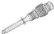
Dipstick 1
APPLICATIONS
○ Air source of the pneumatic nailer and stapler.
WARNING:
Never use compressor for applications other than compressor for pneumatic nailer and stapler.
PRIOR TO OPERATION
1. Power source
Ensure that the power source to be utilized conforms to the power source requirements specified on the product nameplate.
2. Power switch
Ensure that the knob of the pressure switch is in the "OFF" position (Fig. 2). If the plug is connected to a receptacle while the knob is in the "ON" position, the compressor will start operating immediately and can cause serious injury.

Knob of the pressure switch
Fig. 2
3. Extension cord
When the work area is far away from the power source, use an extension cord of sufficient thickness and rated capacity (refer page 7). The extension cord should be kept as short as practicable.
WARNING:
Damaged cord must be replaced or repaired.
4. Confirm the power receptacle
If the power receptacle only loosely accepts the plug, the receptacle must be repaired. Contact the nearest electric store for repair service. If such a faulty receptacle is used, may cause overheating, resulting in a serious hazard.
5. Dipstick insertion and oil level check
Use a screwdriver or similar tool to remove the plastic cap on the lower part of the cylinder (Fig. 3).

Fig. 3
Insert the accessory dipstick all the way to the bottom. Remove the dipstick and make sure the oil level is within the range of the dipstick notches (Fig. 4).

Fig. 4

WARNING:Drain tank to release air pressure before removing the dipstick.

WARNING: Make sure air vent in dipstick is free from debris. If air vent is blocked pressure can build in crankcase causing damage to compressor and possible personal injury.
When the oil volume is insufficient, refer to the section "Oil change-oil topping off" on page 13 for a description of how to supply the oil.
6. Air coupler installation
Screw in the air coupler to the joint (Refer to Fig. 1
and Fig. 6). The screw size of the joint is 3/8". Use an air coupler which has the same screw size.
7. Right running position
Position the compressor on a flat surface or one with an inclination of 10^ at the most, in a well ventilated area away from atmospheric agents and not in explosive areas (Fig. 5).

CAUTION : In order to avoid damaging the compressor, do not allow the unit to be tilted more than 10^ when operating.
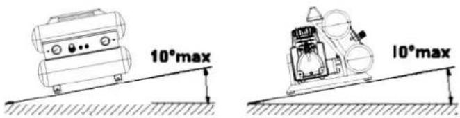
Fig. 5
TRANSPORT
Push the knob of the pressure switch to "OFF" and disconnect it from the power source before move the compressor. Transport the compressor in the correct manner.
OPERATION
1. Start up
Insert the plug into the receptacle and start the compressor by pulling the knob of the pressure switch to "ON" (Refer to Fig. 2).

WARNING: Do not stop or start the compressor by use of the plug. Always use "ON/OFF" knob located on the pressure switch.
The operation of the compressor is automatic and is controlled by the pressure switch which stops it when the pressure in the air-tank reaches the maximum level and restart it when the air pressure drops during use to the restart level.
The motor of the compressor is fitted with a thermal protection with manual reset (push-button), which stops the compressor when the temperature is too high. Should this be tripped, the compressor will restart only if reset is done.
2. Adjustment of working pressure
Unlock the knob of the pressure reducer pulling it up, adjust the pressure to the required level by turning the knob clockwise to increase and counterclockwise to decrease.
A pressure gauge (B) is provided to know when the required pressure is reached, lock the knob by pushing it down firmly (Refer to Fig. 6).
English
When adjusting the pressure, check and make sure that a pressure gauge for the tank has the pressure level that is higher than that of the pressure to be adjusted.
It is also imperative that you make adjustment by slowly starting up the pressure from the level that is lower than the pressure to be adjusted.
WARNING:
Check the manufacturer's maximum pressure rating for nailers, staplers and accessories. Compressor outlet pressure must be regulated so as to never exceed the maximum pressure rating of the nailers, staplers and accessories.
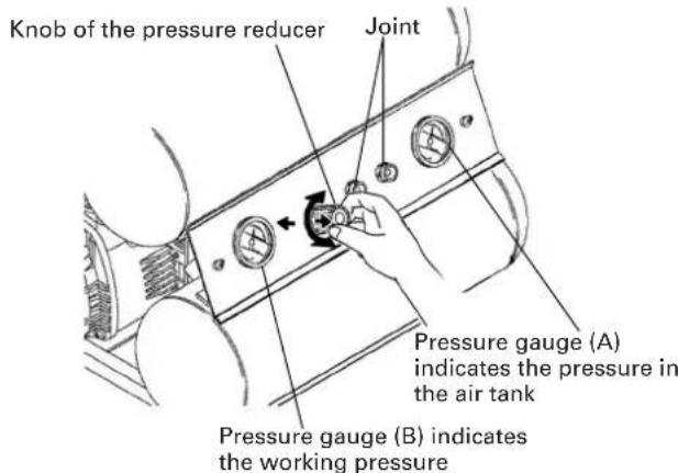
Fig. 6
3. Shutdown
(1) Push the knob of the pressure switch to "OFF" (Refer to Fig. 1 and Fig. 2).
(2) Unplug the plug from power source.
(3) Open the drain cock located at the lower part of the tank (Fig. 7).

Fig. 7
4. About the thermal protector
The thermal protector operates to stop the motor when a problem such as a motor overload, etc., occurs. If the motor should stop during operation, proceed as follows.
(1) Push the pressure switch knob to the "OFF" position and disconnect the plug from the receptacle (Fig. 2).
(2) If the extension cord does not conform to the specifications given on page 7 replace with an extension cord such as that shown on page 7. If the capacity of the power supply is insufficient, increase the power supply capacity to remove the cause of a flow of excessive current (over-current).
(3) Wait approximately 5 minutes, then press the reset switch of the thermal protector (Fig. 8).
(4) Start up. If the motor still stops during operation, please contact the service center.
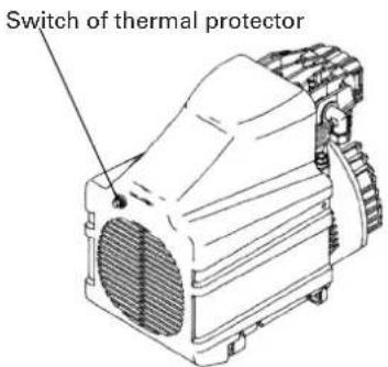
Fig. 8
MAINTENANCE

WARNING: Disconnect the compressor from the power source and remove the compressed air from the air tank before performing the maintenance operations. Allow the compressor to cool before performing the maintenance operations.
1. Cleaning the intake filter
Remove the intake filter (Refer to Fig. 1) every 50 hours or once a week and clean the inside of the intake filter and the filter element with compressed air (Fig. 9). Use a phillips screwdriver to disassemble intake filter.

WARNING: Never clean filter element with a flammable liquid or solvent.

CAUTION : Do not operate without the intake filter.

Fig. 9
NOTE: Replace the filter element when it becomes dirty.
2. Draining tank
Drain tank daily or after 4 hours of use. Open drain fitting and tilt compressor to empty accumulated water (Refer to Fig. 7).
3. Oil change-oil topping off

CAUTION : Overfilling with oil will cause premature compressor failure. Do not overfill.
(1) Within the first 50 hours of operation, completely replace the oil of the pumping element. Unfasten the oil drain cap on the casing cover, drain all the oil, and screw the cap back on (Refer to Fig. 1 and Fig. 10).
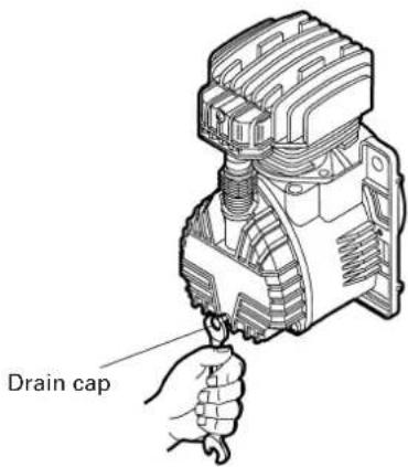
Fig. 10
Pour oil into the hole of the dipstick. To the level indicated on the dipstick (Refer to Fig. 4). For oil replacement, follow the table below.
OIL TYPE
SAE 5W50 SYNTHETIC OIL (-20°+120°F) For both summer and winter use SAE 10W40 MULTI-GRADED OIL (+50°+120°F) For warm weather use only
(2) Check the oil level of the pumping element every 50 hours or once a week.
(3) Change the oil every 300 working hours or every 6 months.
SERVICE AND REPAIRS
All quality compressors will eventually require servicing or replacement of parts because of wear from normal use. To assure that only authorized replacement parts will be used, all service and repairs must be performed by a HITACHI AUTHORIZED SERVICE CENTER, ONLY.
NOTE: Specifications are subject to change without any obligation on the part of the HITACHI.
INFORMATIONS IMPORTANTES
natural_image
Simple line drawing of a plug and two electrical socket (no text or symbols)| Item No. | Code No. Part | Name Q'ty Reference No. | Item No. | Code No. | Part Name | Q'ty | Reference No. | ||
| 1 | 884-420 | Tank 15157200008 | 58 | 881-399 | Screw 4 7011040000 | ||||
| 2 | Rubber 472600 | 10000 | 59 | 882-585 | Cover | 151 | 10061008 | ||
| 3 | 881-573 | Washer | 47030 | 190000 | 60 | 882-587 | Chock | 175 | 1150000 |
| 4 | Screw 474221 | 0000 | 61 | 881-478 | Ball bearing | 170 | 60010000 | ||
| 5 | Hand 472500 | 60000 | 62 | 884-446 | Motor | 140 | 13260000 | ||
| 6 | Screw 4742408 | 0000 | 63 | 884-447 | Rotor | 150 | 90340008 | ||
| 7 | Disc a 892-bp(Drain cock) 27130440000 | 64 | 884-448 | Crank case | 150 | 70320008 | |||
| 8 | Infeed 89563 | 17328620000 | 65 | 881-474 | SMIM ring | 170 | 71020000 | ||
| 9 | Joint 887082970000 | 66 | 881-466 | Ball bearing | 170 | 60060000 | |||
| 10 | 884-426 | Insert | 470 | 18120000 | 67 | 881-562 | Crank shaft | 150 | 40450008 |
| 11 | 882-628 | Non return valve | 171 | 90080000 | 68 | 881-463 | Ring | 170 | 41010000 |
| 12 | 884-428 | Infeed tube | 172 | 30880000 | 69 | 881-469 | Dipstick | 171 | 81060000 |
| 13 | 882-611 | Pressure switch | 172 | 50640000 | 70 | 882-622 | Carter cover (Casing cover) | 1 | 7650120000 |
| 14 | 881-680 | Joint 17084240000 | 71 | 884-450 | Drain cap | 170 | 11430000 | ||
| 15 | 881-496 | Tube | 172 | 30010000 | 72 | 881-472 | Screw 3 7012100000 | ||
| 16 | 881-493 | Safety valve | 171 | 92270000 | 73 | 881-473 | Gasket 1 7078460000 | ||
| 17 | 881-513 | Plug | 170 | 90070000 | 74 | 881-465 | Stud bolt | 270 | 15020000 |
| 18 | 881-505 | Joint 17081140000 | 75 | 884-451 | Tube | 172 | 30080000 | ||
| 19 | 881-504 | Blocking nut | 170 | 23040000 | 76 | 881-496 | Tube | 172 | 30010000 |
| 20 | 881-472 | Screw 17012100000 | 77 | 884-452 | Base | 150 | 11930008 | ||
| 21 | 881-496 | Tube | 172 | 30010000 | 78 | 884-453 | Knob | 271 | 1660000 |
| 22 | 884-429 | Instrumental panel | 151 | 66640008 | 79 | 884-454 | Start valve 1 7196220000 | ||
| 23 | 884-430 | Pressure gauge | 271 | 10410000 | Parts are subject to change without any obligation on the part of HITACHI due to improvements. | ||||
| 24 | 881-509 | Joint 27085790000 | |||||||
| 25 | 884-431 | Screw 27012280000 | |||||||
| 26 | 884-432 | Joint 27080240000 | |||||||
| 27 | 881-678 | Joint 17085170000 | |||||||
| 28 | 884-433 | Joint 17080780000 | |||||||
| 29 | 884-434 | Joint 17080970000 | |||||||
| 30 | 881-510 | Pressure reducer | 171 | 100120000 | |||||
| 31 | 884-435 | Mainfold | 171 | 96950000 | |||||
| 32 | 881-552 | Joint 17084040000 | |||||||
| 33 | 881-588 | Thermal protector | 174 | 10690000 | |||||
| 34 | 881-551 | Screw 47011220000 | |||||||
| 35 | 884-436 | Plate | 174 | 58031000 | |||||
| 36 | 881-553 | Filtering element | 172 | 10010000 | |||||
| 37 | 884-437 | Intake filter | 172 | 10470000 | |||||
| 38 | 884-438 | Head | 175 | 70090000 | |||||
| 39 | 884-439 | Gaskets kit | 140 | 83390000 | |||||
| 40 | 884-440 | Valve plate | 174 | 59530000 | |||||
| 41 | 881-515 | Capacitor | 173 | 10430000 | |||||
| 42 | 884-441 | Cable | 173 | 27830000 | |||||
| 44 | 884-442 | Cylinder | 175 | 75240000 | |||||
| 45 | 881-489 | Nut | 270 | 20070000 | |||||
| 46 | 884-443 | Housing | 171 | 51690000 | |||||
| 48 | 881-559 | Piston rings | 140 | 80020000 | |||||
| 49 | 881-560 | Piston pin | 170 | 50020000 | |||||
| 50 | 881-463 | Ring | 270 | 41010000 | |||||
| 51 | 881-561 | Con rod | 150 | 50150008 | |||||
| 52 | 881-567 | Piston | 172 | 20020000 | |||||
| 53 | 881-488 | Capacitor | 173 | 10140000 | |||||
| 54 | 881-565 | Fan | 172 | 20070000 | |||||
| 55 | 884-444 | Screw | 170 | 13060000 | |||||
| 56 | 884-445 | Handle | 172 | 88020000 | |||||
| 57 | 881-480 | Tension rod | 270 | 18010000 | |||||
Parts are subject to change without any obligation on the part of HITACHI due to improvements.
Issued by

Hitachi Koki Co., Ltd.
Shinagawa Intercity Tower A, 15-1, Konan 2-chome,
Minato-ku, Tokyo 108-6020, Japan
Distributed by

Hitachi Koki U.S.A., Ltd.
3950 Steve Reynolds Blvd.
Norcross, GA 30093

Hitachi Koki Canada Co.
6395 Kestrel Road
Mississauga ON L5T 1Z5
309
Code No. C99125561
Printed in Italy
- WARNING
- ⚠ AVERTISSEMENT
- SAFETY
- - TABLE DES MATIÈRES
- Français
- SÉCURITÉ
- UTILISATION ET ENTRETIEN
- ÍNDICE
- Español
- MEANINGS OF SIGNAL WORDS
- IMPORTANT SAFETY INSTRUCTIONS FOR USE OF THE COMPRESSOR
- READ ALL INSTRUCTIONS
- NEVER OPERATE WITHOUT ALL GUARDS IN PLACE.
- ALWAYS WEAR PROTECTION.
- PROTECT YOURSELF AGAINST ELECTRIC SHOCK.
- DISCONNECT THE COMPRESSOR.
- AVOID UNINTENTIONAL STARTING.
- STORE COMPRESSOR PROPERLY.
- KEEP WORK AREA CLEAN.
- CONSIDER WORK AREA ENVIRONMENT.
- KEEP CHILDREN AWAY.
- DRESS PROPERLY.
- DON'T ABUSE CORD.
- MAINTAIN COMPRESSOR WITH CARE.
- OUTDOOR USE EXTENSION CORDS.
- STAY ALERT.
- CHECK DAMAGED PARTS AND AIR LEAK.
- NEVER USE COMPRESSOR FOR APPLICATIONS OTHER THAN THOSE SPECIFIED.
- HANDLE COMPRESSOR CORRECTLY.
- KEEP ALL SCREWS, BOLTS AND COVERS TIGHTLY IN PLACE.
- KEEP MOTOR AIR VENT CLEAN.
- OPERATE COMPRESSOR AT THE RATED VOLTAGE.
- NEVER USE A COMPRESSOR WHICH IS DEFECTIVE OR OPERATING ABNORMALLY.
- DO NOT WIPE PLASTIC PARTS WITH SOLVENT.
- USE ONLY GENUINE HITACHI REPLACEMENT PARTS.
- DO NOT MODIFY THE COMPRESSOR.
- PUSH THE KNOB OF THE PRESSURE SWITCH TO OFF WHEN THE COMPRESSOR IS NOT USED.
- DO NOT DIRECT AIR STREAM AT BODY.
- DRAIN TANK.
- DO NOT STOP COMPRESSOR BY PULLING OUT THE PLUG.
- MAKE SURE THE COMPRESSOR OUTLET PRESSURE IS SET LOWER THAN THE MAXIMUM OPERATING PRESSURE OF THE TOOL.
- DO NOT ATTEMPT TO OPERATE THIS
- COMPRESSOR WITHOUT FIRST ADDING OIL TO THE CRANKCASE.
- THE SAFETY VALVE MUST WORK PROPERLY.
- USE OF THIS PRODUCT WILL EXPOSE YOU TO
- CHEMICALS KNOWN TO THE STATE OF CALIFORNIA.
- REPLACEMENT PARTS
- SAFETY — Continued
- GROUNDING INSTRUCTIONS
- EXTENSION CORD
- WARNING:
- SAVE THESE INSTRUCTIONS AND
- MAKE THEM AVAILABLE TO OTHER USERS OF THIS TOOL!
- NAME OF PARTS
- ACCESSORY
- STANDARD ACCESSORY
- APPLICATIONS
- PRIOR TO OPERATION
- Power source
- Power switch
- Extension cord
- Confirm the power receptacle
- Dipstick insertion and oil level check
- Air coupler installation
- Right running position
- TRANSPORT
- OPERATION
- Start up
- Adjustment of working pressure
- English
- Shutdown
- About the thermal protector
- MAINTENANCE
- Cleaning the intake filter
- Draining tank
- Oil change-oil topping off
- OIL TYPE
- SERVICE AND REPAIRS
- INFORMATIONS IMPORTANTES
- Hitachi Koki Co., Ltd.
- Hitachi Koki U.S.A., Ltd.
- Hitachi Koki Canada Co.
Brand : HITACHI
Model : EC 119
Category : Compressor