172.567 - Mixer Skytec - Free user manual and instructions
Find the device manual for free 172.567 Skytec in PDF.
| Product type | Mixing console |
| Brand | Skytec |
| Model | 172.567 |
| Power supply | 220 Vac, 50 Hz |
| Mono input channels | 4 channels with balanced mic input (XLR) and line input (6.3 mm jack) |
| Stereo input channels | 4 channels with 6.3 mm jack line input (L/Mono and R) |
| Mono equalizer | 3-band: High (±15 dB), Mid with adjustable frequency (±15 dB), Low (±15 dB) |
| Stereo equalizer | 4-band: High (±15 dB), Hi Mid (±15 dB), Lo Mid (±15 dB), Low (±15 dB) |
| High-pass filter | Low Cut at 75 Hz (-3 dB) on mono channels |
| Phantom power | 48 V, switchable for all balanced mic inputs |
| Main outputs | Stereo output (XLR and 6.3 mm jack), GRPS 1-2 output (6.3 mm jack) |
| AUX outputs | 2 AUX sends (pre-fade and post-fade), 2 AUX returns |
| Headphone output | 6.3 mm jack with adjustable level |
| Signal-to-noise ratio | 112 dB |
| Max. output level | +22 dBu (balanced) |
| Usage | Indoor only |
| Safety | Do not open the housing; disconnect during a thunderstorm; use a grounded 230 Vac/50 Hz outlet |
| Maintenance and cleaning | Do not use sprays for potentiometers; consult a specialist in case of problems |
| Warranty | Void if misused or if instructions are not followed |
Frequently Asked Questions - 172.567 Skytec
User questions about 172.567 Skytec
0 question about this device. Answer the ones you know or ask your own.
Ask a new question about this device
Download the instructions for your Mixer in PDF format for free! Find your manual 172.567 - Skytec and take your electronic device back in hand. On this page are published all the documents necessary for the use of your device. 172.567 by Skytec.
USER MANUAL 172.567 Skytec
natural_image
Exterior view of a multi-tiered audio recording device with multiple knobs and control knobs (no visible text or labels)Congratulations on the purchase of this SkyTec mixer. Please read this manual carefully prior to using the unit.
Warning:
- Read the manual prior to using the unit.
- Keep the manual for future reference.
- Keep the packaging for safer transport in its original packaging
- For indoor use only.
- Prior to the first use, have the unit checked by a qualified person.
- The unit contains voltage carrying parts. DO NOT open the mixer.
- When you unplug the unit from the mains always pull the plug, never the lead.
- Never plug or unplug the unit with wet hands.
- If the plug and/or mains lead are damaged, they need to be repaired by a qualified technician.
- If the unit is damaged to an extent that you can see internal parts, do not plug the unit into a mains outlet.
- Repairs and lamp replacement has to be carried out by a qualified technician.
- Only connect this unit to an earthed mains outlet of 230Vac/50Hz and 10-16A.
- Do no place the unit near heat sources.
- Always unplug the unit during a thunderstorm or when it is not in use.
- If the unit has not been used for a longer period of time, condensation can occur inside the housing. Please let the unit reach room temperature prior to use.
- Keep out of the reach of children.
- All channel controls and the master volume control must be set to zero prior to switching the unit on.
- Set the channel slider controls slowly. Fast variation can overload the speakers.
- To prevent clipping of the amplifier do not set the volume level too high.
- Switch the amplifier on at latest and switch it off at first.
- Do not use cleaning sprays for the slider controls. The residues of these spray cause dust deposits in the controls. If a problem occurs, please consult a specialist.

text_image
CAUTION RISK OF ELECTRIC SHOCK DO NOT OPENMONO INPUT CHANNELS
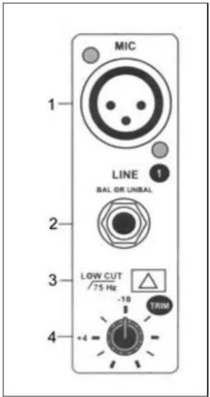
1. BALANCED INPUT
Electronically balanced input for standard XLR connectors. Features a 48V phantom power (to be switched on via (35))
2. LINE INPUT
This unbalanced input accepts balanced and unbalanced microphones, turntables, keyboard, etc.
3. LOW CUT
This push button improves the use of the microphone. When the low cut function is activated you have fewer problems with noise, interference and pop noises.
4. TRIM
This function allows you to set the input sensitivity of each channel to the constant level of the input signal.
5. HIGH
Sets the high frequencies on each channel. Leave this knob in the "0" position first. Set the signal once the music has started to play in order not to damage the speakers. Turn cw to increase the higher frequencies and ccw to reduce them.
6. FREQUENCY & MID
This equalization function has a "bell" reaction with a fixed Q fader of 1.5. The frequency can be set between 100 & 8000 Hz and the volume between -15 & +15 dB.
7. LOW
This knob sets the low frequency range of each channel. Leave this knob in the "0" position first. Set the signal once the music has started to play in order not to damage the speakers. Turn cw to increase the lower frequencies and ccw to reduce them
text_image
MIC 1 LINE 1 BAL OR UNBAL 2 3 LOW CUT /75 Hz -10 +4 TRIM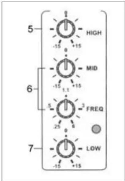
text_image
5 HIGH -15 +15 0 6 MID -15 +15 1.1 5 FREQ -25 6 7 -15 +15 LOW8. AUX 1
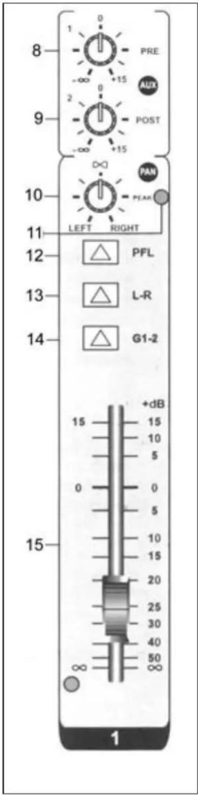
This AUX send control is pre-fade, post-EQ. Therefore the signal is not controlled by the position of the fader and the routing status of the channel. This send function is very convenient to cross monitor signals that have to be controlled separately from the PA installation.
9. AUX 2
This AUX send control is post-fade, post-EQ. Therefore the signal is sensitive to changes in the fader position. It is normally used to feed an audio signal to an effect unit. As the signals are always sent back into the mixer, the fader must be able to control these signals.
10. PAN
The PAN control feeds continuously variable quantities of the post-fader signal to the left or right and G1 or G2 main busses. In the centre position / "∞" the same signal is sent to the left and right and the G1 and G2 main busses.
11. PEAK
A red LED lights up when the peak signal reaches the maximum value that the mixer can handle. If this lasts over a longer period of time, you might damage the unit. The LED lights up at a volume level of 5 dB below clipping.
12. PFL
If this button is pressed, you can monitor the signal via headphones. This applies only to channels where the PFL function is switched on. All other channel can then not be monitored through the headphones
13. STEREO
When this button is pressed, you can use the L-R master faders to allocate a stereo position to the signal of this channel over the output signal.
14. GRPS 1-2
When this button is pressed, you can use the G1-2 master fader. Now, the signal is bundled with all other channels on which this function is activated. The L-R master faders are inactive now.
15. CHANNEL FADER
This slider control sets the volume of that channel. Set it to the "0" position when you connect a signal. Push the slider control upwards until the required output volume is reached. Please note, you can further change the volume of this channel via one of the master faders.
text_image
8 PRE -∞ +15 AUX POST 9 -∞ +15 10 PAN LEFT RIGHT 11 12 PFL 13 L-R 14 G1-2 15 +dB 15 10 5 0 5 10 15 20 25 30 40 50 ∞ ∞ 1STEREO INPUT CHANNELS
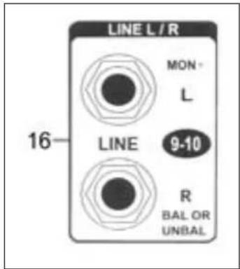
16. LEFT (MONO) / RIGHT
6.3 mm jack input for connection of a Line signal. If L+R are both connected, this channel is stereo. If only the left input is connected, a mono signal is fed to the left and the right bus (the signal is simply spread over the left and the right bus). If you connect only the right input, the signal is fed only to the right bus.
17. HIGH
This knob controls the high frequencies per channel. Set this button always in the "0" position first. Control the signal once the music has started playing in order to prevent damage to the speakers. Turn cw to increase the high frequencies and ccw to reduce them.
18. HI MID & LO MID
This knob controls the medium range frequencies per channel. Set this button always in the "0" position first. Control the signal once the music has started playing in order to prevent damage to the speakers. Turn cw to increase the medium frequencies and ccw to reduce them.
19. LOW
This knob controls the low frequencies per channel. Set this button always in the "0" position first. Control the signal once the music has started playing in order to prevent damage to the speakers. Turn cw to increase the low frequencies and ccw to reduce them.
text_image
LINE L / R MON L 16 LINE 9-10 R BAL OR UNBAL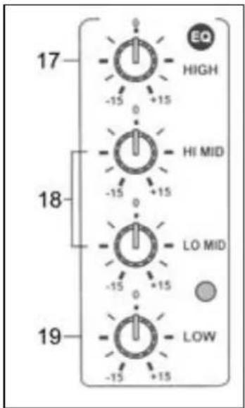
text_image
17 -15 +15 EO HIGH HI MID 18 -15 +15 LO MID -15 +15 19 -15 +15 LOW20. AUX 1
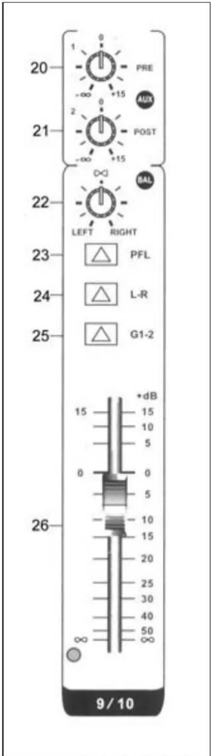
This AUX send control is pre-fade, post-EQ. Therefore the signal is not influenced by the position of the fader and the routing status of the channel. This send function is very convenient to cross monitor signals that have to be controlled separately from the PA installation.
21. AUX 2
This AUX send control is post-fade, post-EQ. Therefore the signal is sensitive to changes in the fader position. It is normally used to feed an audio signal to an effect unit. As the signals are always send back into the mixer, the fader must be able to control these signals.
22. BAL
The BAL control feeds continuously variable quantities of the post-fader signal to the left or right and G1 or G2 main busses. In the centre position "∞" the same signal is sent to the left and right and the G1 and G2 main busses.
23. PFL
If this button is pressed, you can monitor the signal via headphones. This applies only to channels where the PFL function is switched on. All other channel can then not be listened to through the headphones
24. STEREO
When this button is pressed, you can use the L-R master faders to allocate a stereo position to the signal of this channel over the output signal. The L-R master faders are inactive in that case.
25. GRPS 1-2
When this button is pressed, you can use the G1-2 master fader. Now, the signal is bundled with all other channels on which this function is activated. The L-R master faders are inactive now.
26. CHANNEL FADER
This slider control sets the volume of that channel. Set it to the "0" position when you connect a signal. Push the slider control upwards until the required output volume is reached. Please note: you can further change the volume of this channel via one of the master faders.
text_image
20 PRE AUX 21 POST -∞ +15 -∞ +15 22 LEFT RIGHT 23 PFL 24 L-R 25 G1-2 26 +dB 15 15 10 5 0 0 5 10 15 20 25 30 40 50 ∞ 9 / 10MASTER SECTION
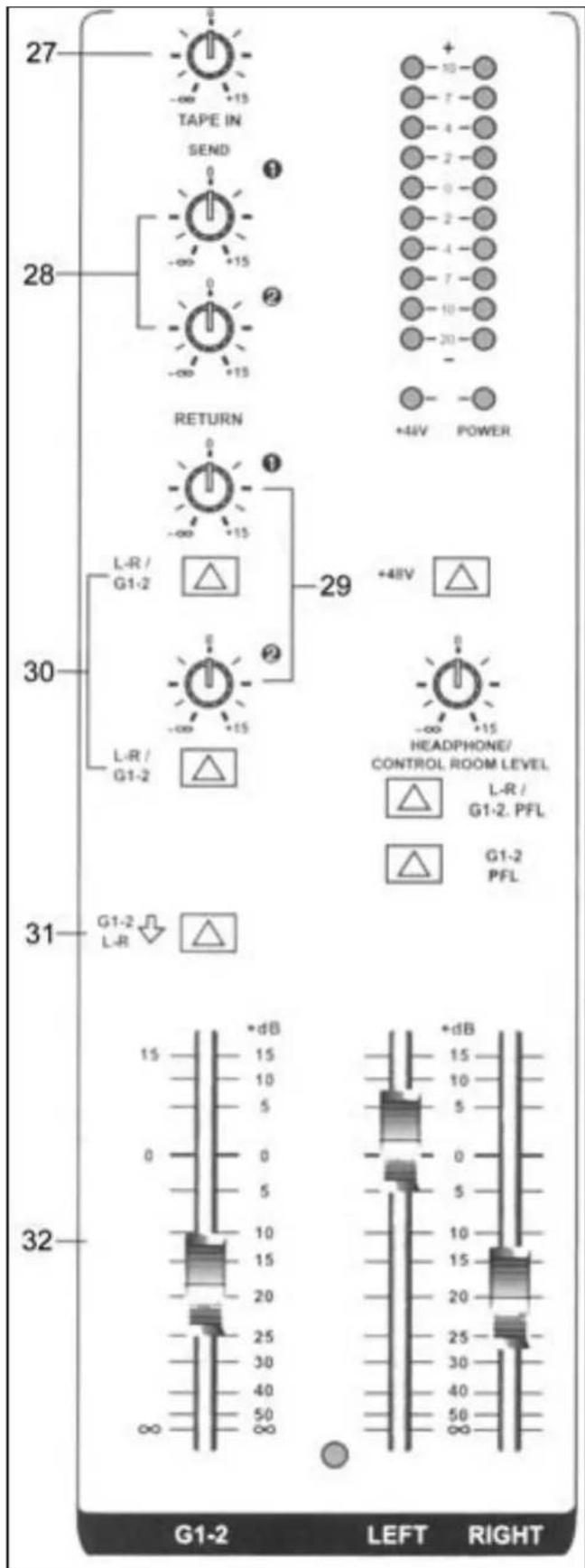
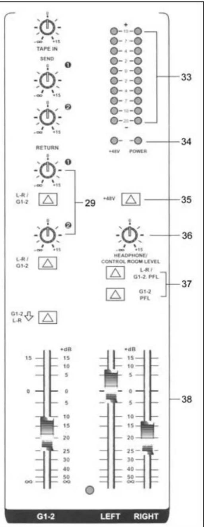
27. TAPE LEVEL
This knob changes the volume level of the TAPE IN if this input is connected. Turn cw to increase the level and ccw to reduce it
28. AUX 1-2 SENDS
This knob changes the volume level of the AUX Send if this output is connected. Turn cw to increase the level and ccw to reduce it
29. AUX RETURN 1-2
This knob changes the volume level of the AUX Return input signal. Turn cw to increase the level and ccw to reduce it
30. ST/G1-2
If this switch is not pressed, the return signal will be sent to the stereo output. If the switch is pressed in, the return signal will be sent to the G1-2 output.
31. ST/G1-2
If this switch is pressed, the G1-2 mix output signal is sent to the stereo bus. Thus the G1-2 busses can mix two mono subgroups into a single output signal when no stereo sound is required.
32. GRPS 1-2 OUTPUT FADER
This slider control sets the volume level of the G1-2 bus.
text_image
27 TAPE IN SEND 1 28 RETURN +4kV POWER L-R/ G1-2 29 +4kV 30 L-R/ G1-2 HEADPHONE/ CONTROL ROOM LEVEL L-R / G1-2. PFL G1-2 PFL 31 G1-2 L-R 32 +dB 15 15 10 10 5 5 0 0 5 5 10 10 15 15 20 20 25 25 30 30 40 40 50 50 ∞ ∞ G1-2 LEFT RIGHT33. OUTPUT LEVEL INDICATOR (VU METER)
This VU-meter displays the output levels of the lift and right channels, GPRS1-2, headphones and control room so that you can monitor the output condition of the signal.
34. ON/OFF & PHANTOM LEDs
The LEDs light up when their functions are switched on.
35. PHANTOM POWER SWITCH
If you press this button all balanced microphone inputs are powered by 48V which allows the use of condenser microphones.
36. HEADPHONE / CONTROL ROOM LEVEL
This single volume control sets the volume level of the headphones and of the monitors. Turn cw to increase the volume and ccw to lower it.
37. HEADPHONE SWITCH
If the L-R / G1-2 PFL button is not pressed in, the output signal is sent in stereo to the monitors. If the buttons are pressed in, the signal is sent via the headphones. The G1-2 fader allows you to determine the volume level of the headphones.
It's the master fader control of the volume level of a stereo signal. Left and right are controlled separately.
text_image
TAPE IN SEND 1 2 RETURN L-R / G1-2 1 29 +48V POWER 33 34 35 36 37 HEADPHONE/ CONTROL ROOM LEVEL L-R / G1-2. PFL G1-2 PFL G1-2 L-R +dB 15 +dB 15 10 5 0 0 5 10 15 20 25 30 40 50 ∞ G1-2 LEFT RIGHT 38MIXER OUTPUT SECTION
text_image
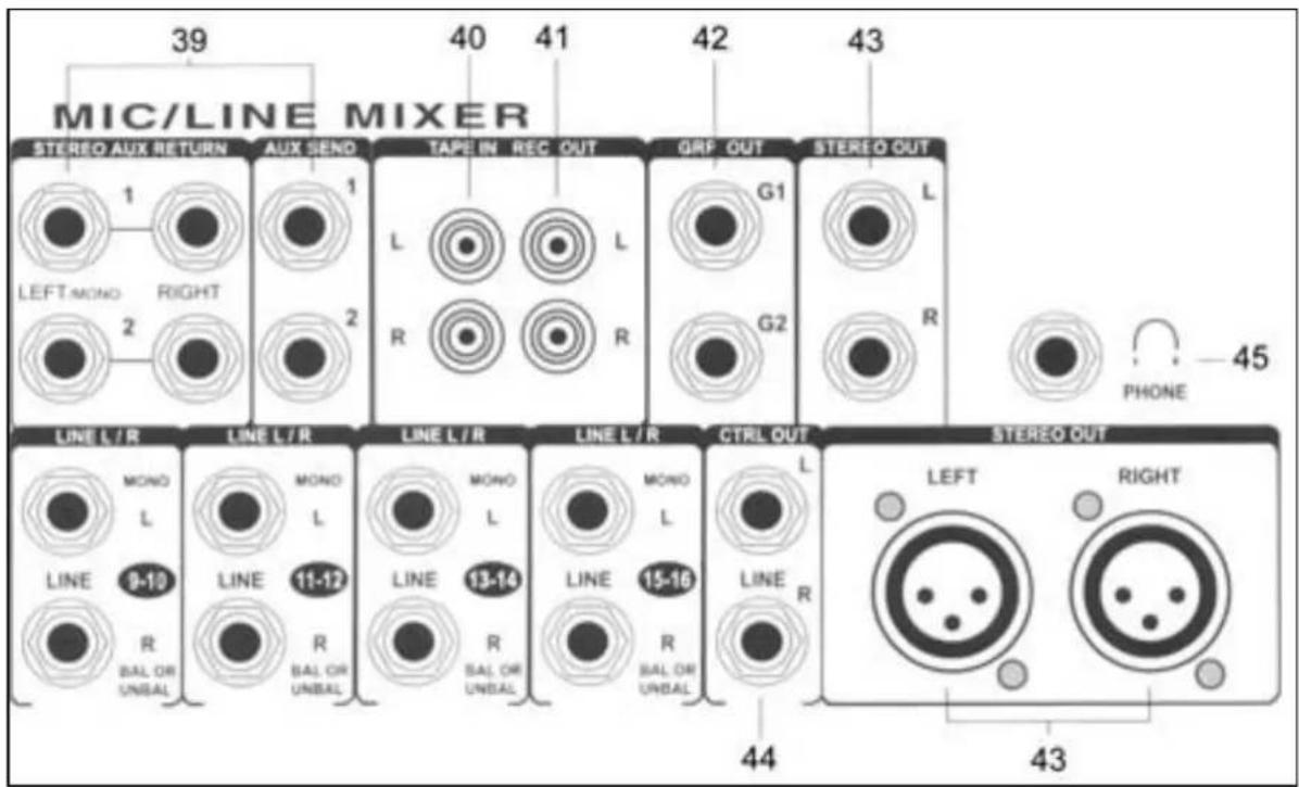
MIC/LINE MIXER 39 40 41 42 43 STEREO AUX RETURN AUX SEND TAPE IN REC OUT GRP OUT STEREO OUT LEFT MONO RIGHT L R G1 L 2 2 R G2 R LINE L/R LINE L/R LINE L/R LINE L/R CTRL OUT STEREO OUT MONO MONO MONO MONO L LINE 13-14 LINE 15-16 LINE L L BAL OR UNBAL BAL OR UNBAL BAL OR UNBAL BAL OR UNBAL BAL OR UNBAL BAL OR UNBAL BAL OR UNBAL BAL OR UNBAL BAL OR UNBAL BAL OR UNBAL BAL OR UNBAL BAL OR UNBAL BAL OR UNBAL BAL OR UNBAL BAL OR UNBAL BAL OR UNBAL BAL OR UNBAL BAL OR UNBAL BAL OR UNBAL BAL OR UNBAL BAL OR UNBAL BAL OR UNBAL BAL OR UNBAL BAL OR UNBAL BAL OR UNBAL BAL OR UNBAL BA AL OR UNBAL BAL OR UNBAL BAL OR UNBAL BAL OR UNBAL BAL OR UNBAL BAL OR UNBAL BAL OR UNBAL BAL OR UNBAL BAL OR UNBAL BAL OR UNBAL BAL OR UNBAL BAL OR UNBAL BAL OR UNBAL BAL OR UNBAL BAL OR UNBAL BAL OR UNBAL BAL OR UNBAL BAL OR UNBAL BAL OR UNBAL BAL OR UNBAL BAL OR UNBAL BAL OR UNBAL BAL OR UNBAL BAL OR UNBAL BAL OR UNBAL GALA BAL OR UNBAL BAL OR UNBAL BAL OR UNBAL BAL OR UNBAL BAL OR UNBAL BAL OR UNBAL BAL OR UNBAL BAL OR UNBAL BAL OR UNBAL BAL OR UNBAL BAL OR UNBAL BAL OR UNBAL BAL OR UNBAL BAL OR UNBAL BAL OR UNBAL BAL OR UNBAL BAL OR UNBAL BAL OR UNBAL BAL OR UNBAL BAL OR UNBAL BAL OR UNBAL BAL OR UNBAL BAL OR UNBAL BAL OR UNBAL BAL OR UNRAL PHONE 4539. STEREO AUX RETURNS & SENDS
To be connected to all kinds of effect units
40. TAPE INPUT JACK
Connect this jack to a cassette deck for playback
41. RECORD PIN JACK
This jack has to be connected to a cassette deck for recording of the output signal.
42. GRPS 1-2 OUTPUT JACK
Connect this jack to an amplifier to reproduce the G1-2 signal.
43. STEREO OUTPUT JACK (LEFT/RIGHT)
This allows you to connect the output signal to an amplifier via 6.3mm jacks or XLR connectors
44. CONTROL ROOM OUTPUT JACK
For connection to a monitor (active speaker or amplifier)
45. HEADPHONE JACK
To be connected to headphones in order to monitor on each channel the PFL or the L/R and the G1-2.
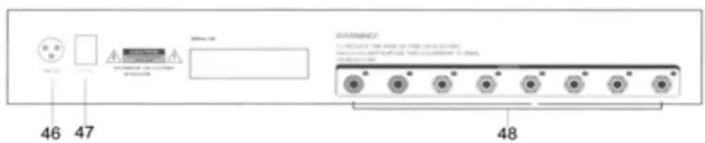
REAR PANEL
46. POWER JACK
Mains power inlet.
47. MAINS SWITCH
Press this button to switch the mixer ON or OFF. The LED (29) lights up when this switch is in ON position.
48. INSERT
To feed the input signals into effect units, electrical instruments, etc.
text_image
46 47 200pc - 48 WARNING: 1. Please note that the main portion of the connection. 2. Please note that the main portion of the connection. 3. Please note that the main portion of the connection.INSTALLATION
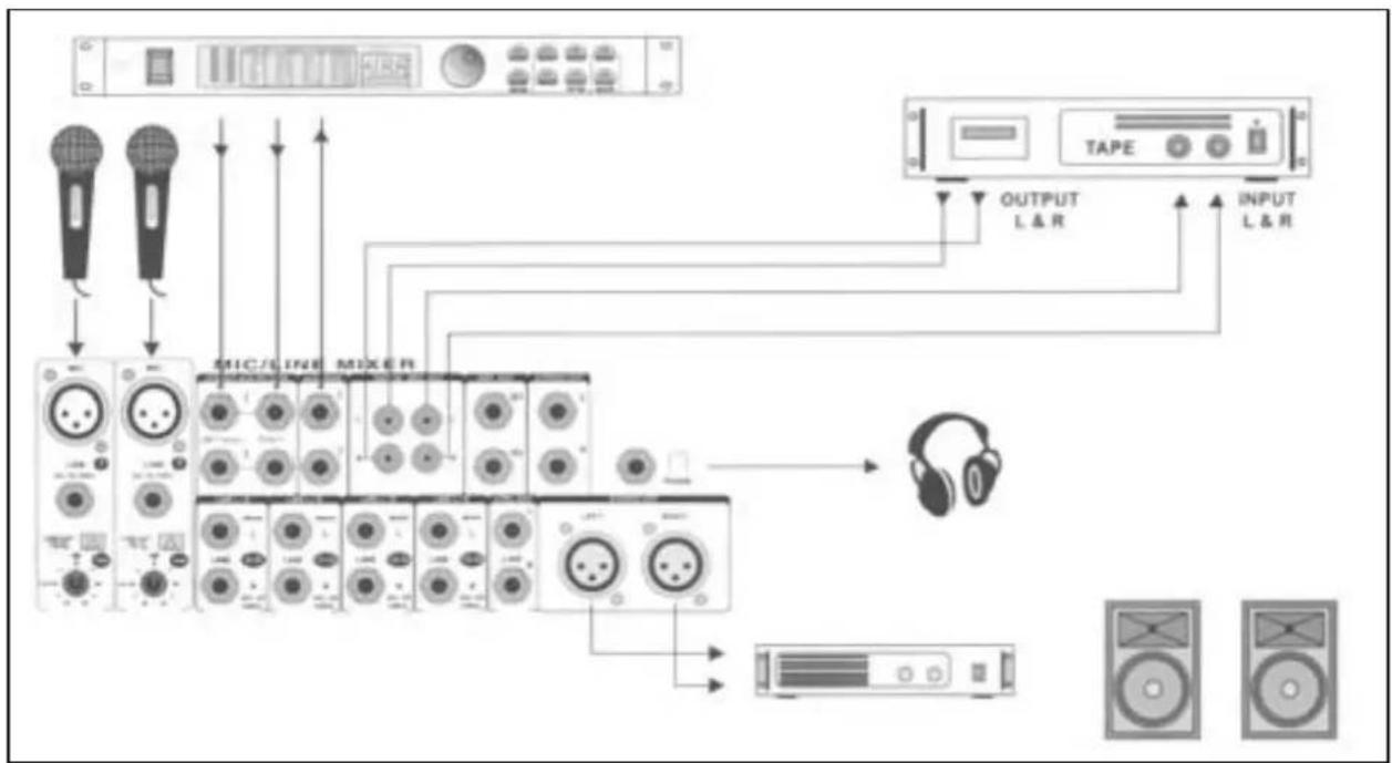
Do not mix up the cable in order to avoid wrong connections. Connect the leads one by one and not all leads on one side first and then all on the other side. In the worst case, you might permanently damage the unit. Figure 2 shows an example of possible connections.
Prior to connecting the mixer, set all controls to "0". You can connect microphone or line units to the mono channels, all kinds of line units to the stereo channels and effect units to the AUX Return. You can also connect Midi instruments to the AUX Return.
If you connect a microphone, make sure that the phantom power is switched OFF. DO NOT use unbalanced units when the phantom power is switched on. Do not short-circuit the 48V circuit of the phantom power to the ground. You might heavily damage the unit.
flowchart
graph TD
    A["Audio Device"] --> B["Microphone"]
    A --> C["Audio Line"]
    A --> D["Mixer"]
    A --> E["Tape"]
    A --> F["Output L & R"]
    A --> G["Input L & R"]
    B --> H["Audio System"]
    C --> H
    D --> H
    E --> H
    F --> H
    G --> H
    H --> I["Headphones"]
CONNECTIONS
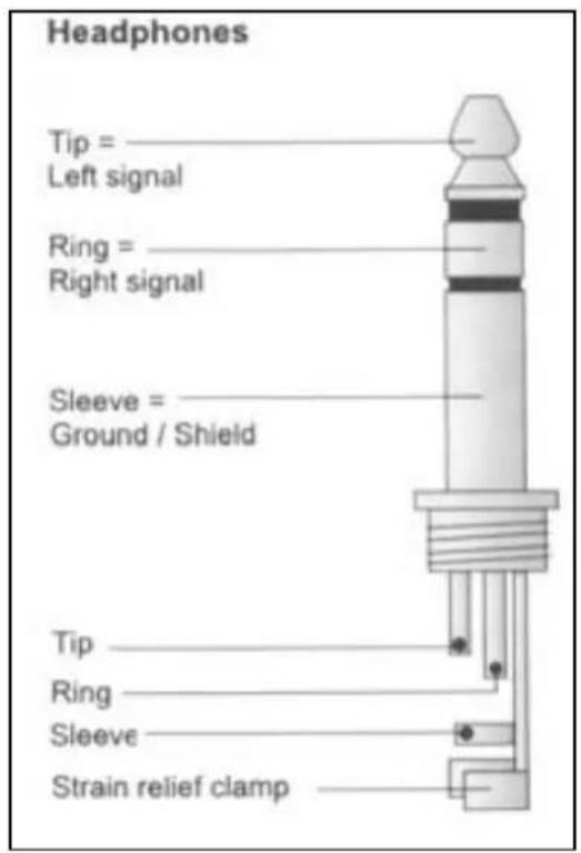
On a balanced in/output, always use balanced equipment. You can use either balanced or unbalanced equipment on an unbalanced in/output. See the drawings below for the equipment that you can use:
text_image
Headphones Tip = Left signal Ring = Right signal Sleeve = Ground / Shield Tip Ring Sleeve Strain relief clamp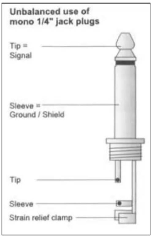
text_image
Unbalanced use of mono 1/4" jack plugs Tip = Signal Sleeve = Ground / Shield Tip Sleeve Strain relief clamp
text_image
Output Pin 1 Pin 2 = (=) Signal Pin 3 = (-) Signal Cable Shield (+) Signal + Hum (+) Signal + Hum Ground Positive → (+)Hum + Signal Negative → (-)Hum + Signal RFI and Hum = Signal + 6 dB
text_image
Balanced use with XLR connectors 1 = Ground / Shield 2 = hot (+ve) 3 = cold (-ve) For unbalanced use pin 1 and pin 3 have to be bridged
text_image
Balanced use of stereo 1/4" jack plugs Tip = hot (+ve) Ring = cold (-ve) Sleeve = Ground / Shield Tip Ring Sleeve Strain relief clamp For connection of balanced and unbalanced plugs, ring and sleeve have to be bridged at the stereo plug.If possible, connect the balanced outputs to other balanced units to avoid interference.
SPECIFICATIONS
Mono inputs
Mic input: ......electronically balanced, discrete input configuration
Frequency response: 10 Hz - 20 kHz (± 3 dB)
Distortion: <0,01% @ +4 dBu (± 1 kHz)
Input impedance: 150 Ohm @ -129.5 dB
TRIM range: +10 dB - +60 dB
Line input: ...... electronically balanced
Frequency response: 10 Hz - 20 kHz (± 3 dB)
Distortion: ....<0,01% @ +4 dBu (± 1 kHz)
Line level range: ....+10 dBu - -40 dBu
Equalizer.
High: 12 kHz (± -15 dB)
Mid: 100 Hz - 8 kHz (± -15 dB)
Low: 80 Hz (± -15 dB)
Stereo inputs
Line input: unbalanced
Frequency response: 10 Hz - 20 kHz (± 3 dB)
Distortion: ....<0,01% @ +4 dBu (± 1 kHz)
Equalizer.
High: 12 kHz (± -15 dB)
Mid bell: 100 Hz - 8 kHz (± -15 dB)
Low: 80 Hz (± -15 dB)
Low cut (high pass) filter: 75 Hz @ -3 dB
Master section
Max output level: ...... + 22 dBu, balanced
AUX send max output level: ....+22 dBu unbalanced
Control room output level: ...... +22 dBu unbalanced
Signal/Noise ratio: ....>112 dB
Power supply: 230 Vac, 50 Hz
- Specifications and design subject to changes without prior notice.
Do not attempt to make any repairs yourself. This would invalid your warranty.
Do not make any changes to the unit. This would also invalid your warranty.
The warranty is not applicable in case of accidents or damages caused by inappropriate use or disrespect of the warnings contained in this manual.
SkyTronic UK cannot be held responsible for personal injuries caused by a disrespect of the safety recommendations and warnings. This is also applicable to all damages in whatever form.
text_image
Headphones Tip = _ Left signal Ring = _ Right signal Sleeve = _ Ground / Shield Tip Ring Sleeve Strain relief clamp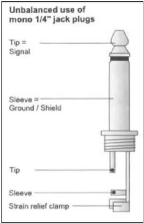
text_image
Unbalanced use of mono 1/4" jack plugs Tip = Signal Sleeve = Ground / Shield Tip Sleeve Strain relief clamp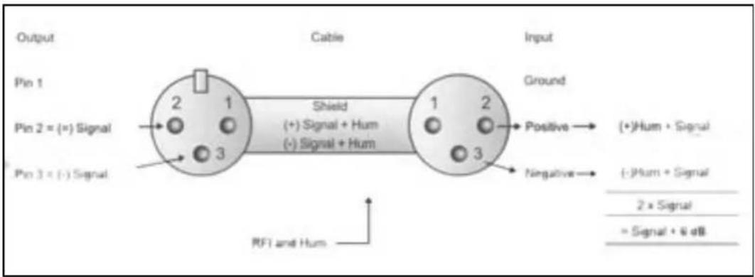
text_image
Output Pin 1 Pin 2 = (=) Signal Pin 3 = (-) Signal Cable Ground Shield (+) Signal + Hum (+) Signal + Hum RFT and Hum Input Positive → (+)Hum + Signal Negative → (-)Hum + Signal 2 x Signal = Signal + 6 dB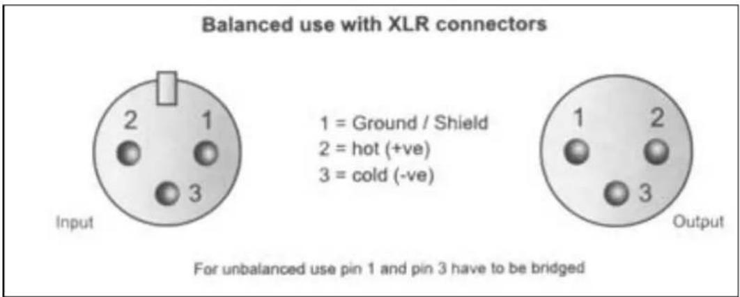
text_image
Balanced use with XLR connectors 1 = Ground / Shield 2 = hot (+ve) 3 = cold (-ve) For unbalanced use pin 1 and pin 3 have to be bridged
text_image
Balanced use of stereo 1/4" jack plugs Tip = hot (+ve) Ring = cold (-ve) Sleeve = Ground / Shield Tip Ring Sleeve Strain relief clamp For connection of balanced and unbalanced plugs, ring and sleeve have to be bridged at the stereo plug.High: 12 kHz (± -15 dB)
Mid: 100 Hz - 8 kHz (± -15 dB)
Low: 80 Hz (± -15 dB)
Stereo ingangen
High: 12 kHz (± -15 dB)
Mid bell: 100 Hz - 8 kHz (± -15 dB)
Low: 80 Hz (± -15 dB)
Low cut (high pass) filter: 75 Hz @ -3 dB
Master sectie
text_image
46 47 48 WARNING: Please note that the rear portion of the device is without any additional connection to the device.INSTALLATION
text_image
Headphones Tip = _ Left signal Ring = _ Right signal Sleeve = _ Ground / Shield Tip Ring Sleeve Strain relief clamp
text_image
Unbalanced use of mono 1/4" jack plugs Tip = Signal Sleeve = Ground / Shield Tip Sleeve Strain relief clamp
text_image
Output Pin 1 Pin 2 = (=) Signal Pin 3 = (-) Signal Cable Shield (+) Signal + Hum (-) Signal + Hum Ground Positive → (+)Hum + Signal Negative → (-)Hum + Signal RFI and Hum = Signal + 6 dB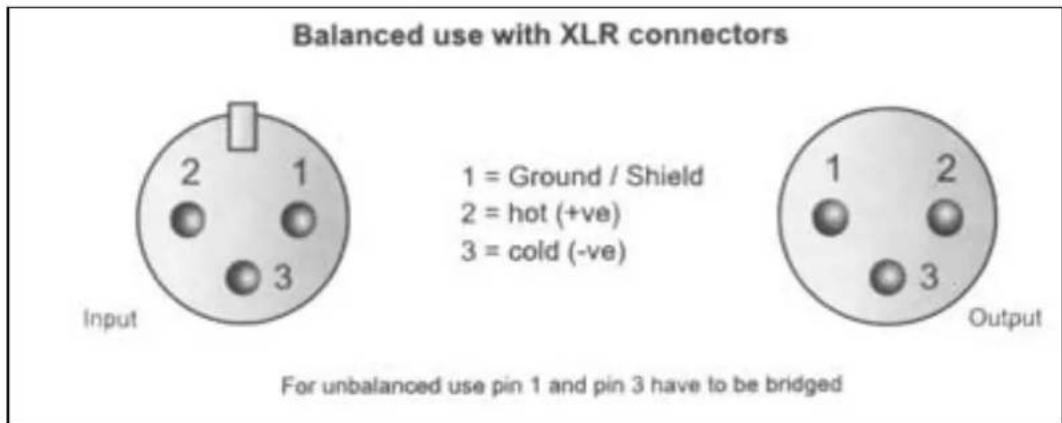
text_image
Balanced use with XLR connectors 1 = Ground / Shield 2 = hot (+ve) 3 = cold (-ve) For unbalanced use pin 1 and pin 3 have to be bridged
text_image
Balanced use of stereo 1/4" jack plugs Tip = hot (+ve) Ring = cold (-ve) Sleeve = Ground / Shield Tip Ring Sleeve Strain relief clamp For connection of balanced and unbalanced plugs, ring and sleeve have to be bridged at the stereo plug.Distorsion: 0,01% @ +4 dBu (± 1 kHz)
Distorsion: 0,01% @ +4 dBu (± 1 kHz)
High: 12 kHz (± -15 dB)
Mid: 2,5 kHz (± -15 dB)
Low: 80 Hz (± -15 dB)
Entrées Stéréo
Distorsion: 0,01% @ +4 dBu (± 1 kHz)
Equalizer.
High: 12 kHz (± -15 dB)
Mi belld: 100 Hz - 8 kHz (± -15 dB)
Low: 80 Hz (± -15 dB)
- GRPS 1-2 AUSGANGSBUCHSE
text_image
46 47 200pc - 48 WARNING: 1. Please note that the main portion of the connection. 2. Please note that the main portion of the connection. 3. Please note that the main portion of the connection.AUFBAU
text_image
Headphones Tip = Left signal Ring = Right signal Sleeve = Ground / Shield Tip Ring Sleeve Strain relief clamp
text_image
Unbalanced use of mono 1/4" jack plugs Tip = Signal Sleeve = Ground / Shield Tip Sleeve Strain relief clamp
text_image
Output Pin 1 Pin 2 = (=) Signal Pin 3 = (-) Signal Cable Shield (+) Signal + Hum (-) Signal + Hum Ground Positive → (+)Hum + Signal Negative → (-)Hum + Signal RFI and Hum = Signal + 6 dB
text_image
Balanced use with XLR connectors 1 = Ground / Shield 2 = hot (+ve) 3 = cold (-ve) For unbalanced use pin 1 and pin 3 have to be bridged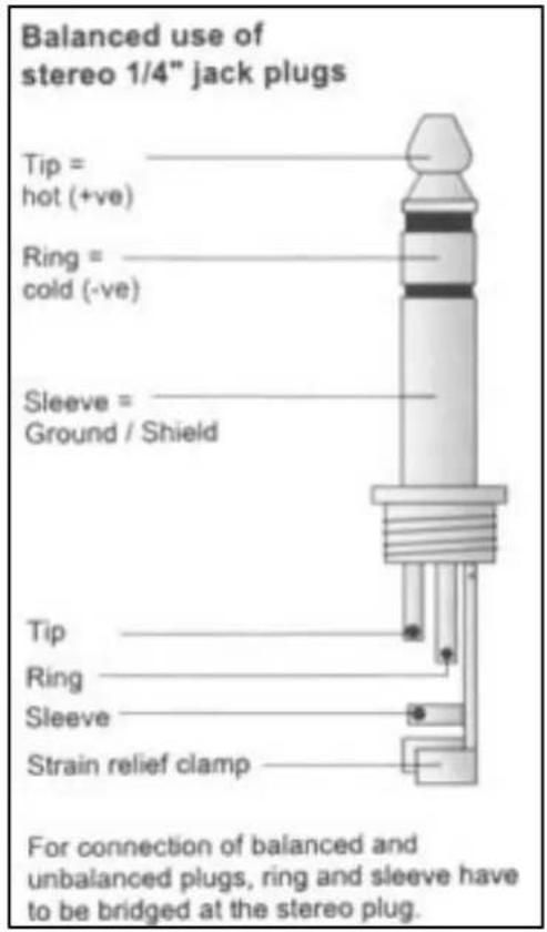
text_image
Balanced use of stereo 1/4" jack plugs Tip = hot (+ve) Ring = cold (-ve) Sleeve = Ground / Shield Tip Ring Sleeve Strain relief clamp For connection of balanced and unbalanced plugs, ring and sleeve have to be bridged at the stereo plug.High: 12 kHz (± -15 dB)
Mid: 2,5 kHz (± -15 dB)
Low: 80 Hz (± -15 dB)
Stereo Eingänge
High: 12 kHz (± -15 dB)
Mid Bell: 100 Hz - 8 kHz (± -15 dB)
Low: 80 Hz (± -15 dB)
Low Cut (Hochpass-) Filter....75 Hz @ -3 dB