
CD686860 - Basket CONSTRUCTA - Free user manual and instructions
Find the device manual for free CD686860 CONSTRUCTA in PDF.

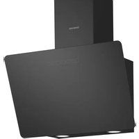
| Product type | Extractor hood |
| Brand | Constructa |
| Model | CD686860 |
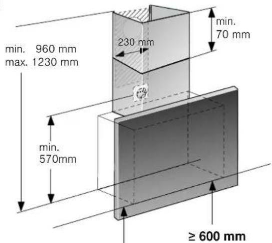
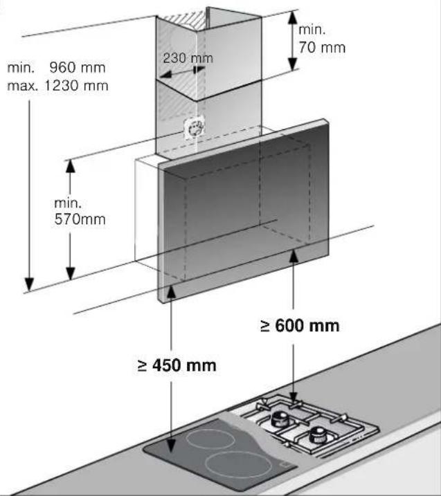
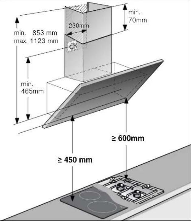
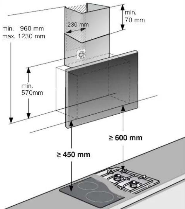
| Dimensions (H x W x D) - configuration A | 960-1230 mm x 230 mm x 570 mm |
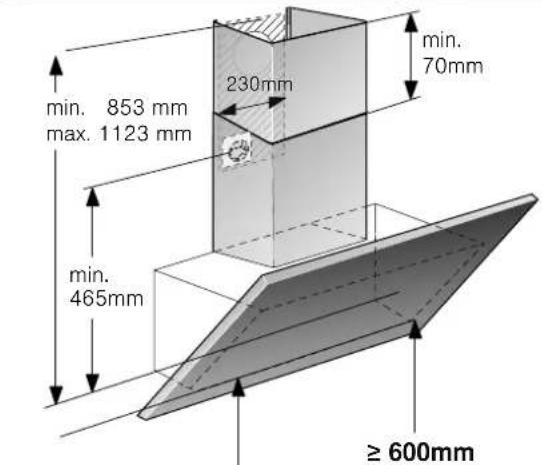
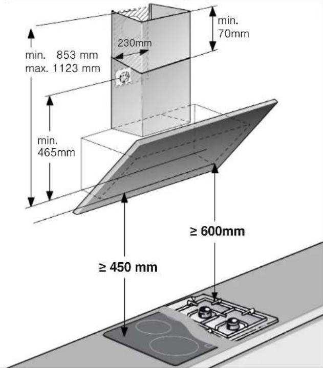
| Dimensions (H x W x D) - configuration B | 853-1123 mm x 230 mm x 465 mm |
| Maximum weight | 40 kg |
| Power supply | 220-240 V, 50 Hz (1.30 m cable) |
| Number of speeds | 3 speeds + intensive speed (6 min then return to speed 3) |
| Control type | Touch |
| Lighting | LED (risk group 1) |
| Grease filter | Metallic, hand washable or dishwasher safe (max 50 °C) |
| Odor filter (optional) | Activated carbon filter for recirculation mode (ref. CZ51AFA0X0, etc.) |
| Operating modes | External air extraction and air recirculation (with optional kit) |
| Exhaust duct diameter | 150 mm (recommended), adaptable to 120 mm with reducing sleeve |
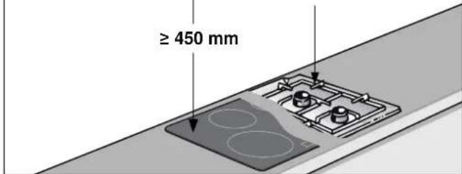
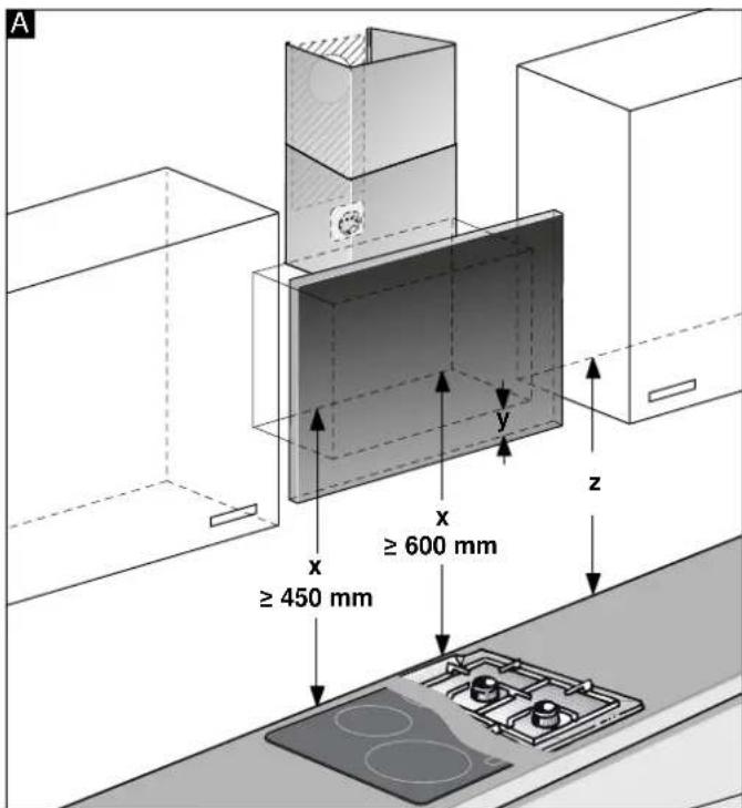
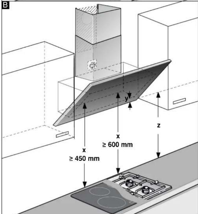
| Minimum safety distance (electric hob) | 450 mm |
| Minimum safety distance (gas hob) | 600 mm |
| Recommended filter maintenance | Every 2 months |
| Energy efficiency class | Not specified |
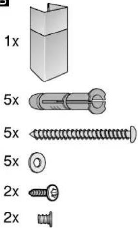
| Included accessories | Mounting template, screws, wall plugs |
| Repairability | Original parts available via after-sales service |
Frequently Asked Questions - CD686860 CONSTRUCTA
User questions about CD686860 CONSTRUCTA
0 question about this device. Answer the ones you know or ask your own.
Ask a new question about this device
Download the instructions for your Basket in PDF format for free! Find your manual CD686860 - CONSTRUCTA and take your electronic device back in hand. On this page are published all the documents necessary for the use of your device. CD686860 by CONSTRUCTA.
USER MANUAL CD686860 CONSTRUCTA
[en] Instructions for installation and use 16
Störungen, was tun?......7
Kundendienst 8
natural_image
Simple line drawing of a house with a checkmark and airflow indicators (no text or symbols)Symbol Erläuterung
Hinweise
Störungen, was tun?
natural_image
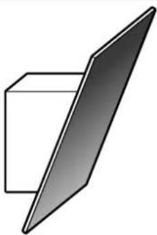
Simple 3D diagram of a rectangular block with a vertical gradient panel on top (no text or symbols)B
natural_image
Simple 3D geometric diagram showing a cube intersected by a plane, no text or symbols presentA|B

natural_image
Illustration of mechanical parts with no visible text or symbolsA
≥ 450 mm
B
natural_image
Two 3D geometric diagrams labeled A and B showing a rectangular prism with a shaded panel, no text or symbols present.natural_image
Simple line drawing of a house with fire and steam pipes, no text or symbols presentnatural_image
Technical illustration of a mechanical assembly with two views (A and B) showing bolted components and mounting brackets (no text or symbols present)Important safety information 17
Environmental protection.... 18
Operating modes.... 19
Operating the appliance 19
Cleaning and maintenance.... 20
Trouble shooting.... 21
Customer service 22
INSTALLATION INSTRUCTIONS.... 23
Important safety information 24
General information 26
Installation 27
INSTRUCTION MANUAL
Additional information on products, accessories, replacement parts and services can be found at wwwConstructa.de and in the online shop wwwConstructa-eshop.com
Intended use
Read these instructions carefully. Only then will you be able to operate your appliance safely and correctly. Retain the instruction manual and installation instructions for future use or for subsequent owners.
The appliance can only be used safely if it is correctly installed according to the safety instructions. The installer is responsible for ensuring that the appliance works perfectly at its installation location.
This appliance is intended for domestic use and the household environment only. The appliance is not intended for use outside. Do not leave the appliance unattended during operation. The manufacturer is not liable for damage which is caused by improper use or incorrect operation.
This appliance is intended for use up to a maximum height of 2000 metres above sea level.
This appliance may be used by children over the age of 8 years old and by persons with reduced physical, sensory or mental capacity or by persons with a lack of experience or knowledge if they are supervised by someone who is responsible for their safety, or have been instructed in how to use the appliance safely and have understood the risks involved in not using it properly.
Children must not play with the appliance.Cleaning and user maintenance must not be performed by children unless
they are over 15 years of age and are supervised.
Keep children below the age of 8 years old at a safe distance from the appliance and power cable.
Check the appliance for damage after unpacking it. Do not connect the appliance if it has been damaged in transport.
This appliance is not intended for operation with an external clock timer or a remote control.
⚠️ Important safety information
Danger of suffocation!
Packaging material is dangerous to children. Never allow children to play with packaging material.
Danger of death!
Risk of poisoning from flue gases that are drawn back in.
Always ensure adequate fresh air in the room if the appliance is being operated in exhaust air mode at the same time as room air-dependent heat-producing appliance is being operated.
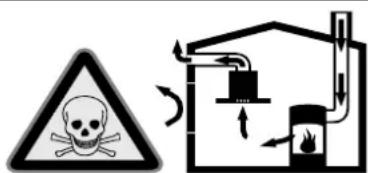
Room air-dependent heat-producing appliances (e.g. gas, oil, wood or coal-operated heaters, continuous flow heaters or water heaters) obtain combustion air from the room in which they are installed and discharge the exhaust gases into the open air through an exhaust gas system (e.g. a chimney).
In combination with an activated vapour extractor hood, room air is extracted from the kitchen and neighbouring rooms - a partial vacuum is produced if not enough fresh air is supplied. Toxic gases from the chimney or the extraction shaft are sucked back into the living space.
■ Adequate incoming air must therefore always be ensured.
- An incoming/exhaust air wall box alone will not ensure compliance with the limit. Safe operation is possible only when the partial vacuum in the place where the heat-producing appliance is installed does not exceed 4 Pa (0.04 mbar). This can be achieved when the air needed for combustion is able to enter through openings that cannot be sealed, for example in doors, windows, incoming/exhaust air wall boxes or by other technical means.
natural_image
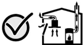
Simple line drawing of a house with a checkmark and fire symbol (no text or labels)In any case, consult your responsible Master Chimney Sweep. He is able to assess the house's entire ventilation setup and will suggest the suitable ventilation measures to you.
Unrestricted operation is possible if the vapour extractor hood is operated exclusively in the circulating-air mode.
Risk of fire!
- Fatty deposits in the grease filter may catch fire. Regularly clean the grease filter. Never operate the appliance without a grease filter.
- Grease deposits in the grease filter may catch fire. Never work with naked flames close to the appliance (e.g. flambéing). Do not install the appliance near a heat-producing appliance for solid fuel (e.g. wood or coal) unless a closed, non-removable cover is available. There must be no flying sparks.
- Hot oil and fat can ignite very quickly. Never leave hot fat or oil unattended. Never use water to put out burning oil or fat. Switch off the hotplate. Extinguish flames carefully using a lid, fire blanket or something similar.
- When gas burners are in operation without any cookware placed on them, they can build up a lot of heat. A ventilation appliance installed above the cooker may become damaged or catch fire. Only operate the gas burners with cookware on them.
- Operating several gas burners at the same time gives rise to a great deal of heat. A ventilation appliance installed above the cooker may become damaged or catch fire. Never operate two gas burners simultaneously on the highest flame for longer than 15 minutes. One large burner of more than 5 kW (wok) is equivalent to the power of two gas burners.
Risk of burns!
The accessible parts become very hot when in operation. Never touch hot parts. Keep children at a safe distance.
Risk of injury!
■ Components inside the appliance may have sharp edges. Wear protective gloves.
- Items placed on the appliance may fall down. Do not place any objects on the appliance.
■ The light emitted by LED lights is very dazzling, and can damage the eyes (risk group 1). Do not look directly into the switched on LED lights for longer than 100 seconds.
Risk of injury!
Risk of trapping body parts when opening and closing the glass front. Do not reach into the area behind the glass panel, and keep your fingers away from the hinges.
Hazard due to magnetism!
Permanent magnets are inserted in the appliance front. They may affect electronic implants, e.g. heart pacemakers or insulin pumps. Wearers of electronic implants must stay at least 10 cm away from the appliance front.
Risk of electric shock!
- A defective appliance may cause electric shock. Never switch on a defective appliance. Unplug the appliance from the mains or switch off the circuit breaker in the fuse box. Contact the after-sales service.
- Incorrect repairs are dangerous. Repairs may only be carried out and damaged power cables replaced by one of our trained after-sales technicians. If the appliance is defective, unplug the appliance from the mains or switch off the circuit breaker in the fuse box. Contact the after-sales service.
- Do not use any high-pressure cleaners or steam cleaners, which can result in an electric shock.
Causes of damage
Caution!
Risk of damage due to corrosion. Always switch on the appliance while cooking to avoid condensation. Condensate can produce corrosion damage.
Always replace faulty bulbs to prevent the remaining bulbs from overloading.
Risk of damage due to ingress of humidity into the electronic circuitry. Never clean operator controls with a wet cloth.
Surface damage due to incorrect cleaning. Clean stainless steel surfaces in the direction of the grain only. Do not use any stainless steel cleaners for operator controls.
Surface damage due to strong or abrasive cleaning agents. Never use strong and abrasive cleaning agents.
Risk of damage from returning condensate. Install the exhaust duct in such a way that it falls away from the appliance slightly (1° slope).
Risk of damage as a result of incorrect loading of design elements. Do not pull design elements. Do not place objects on the design elements or hang objects from them.
Environmental protection
Your new appliance is particularly energy-efficient. Here you can find tips on how to save even more energy when using the appliance, and how to dispose of your appliance properly.
Saving energy
■ During cooking, ensure that there is a sufficient supply of air so that the extractor hood can work efficiently and with a low level of operating noise.
- Adjust the fan speed to the intensity of the cooking fumes. Only use intensive mode where this is required. A lower fan speed means that less energy is consumed.
If there are intensive cooking fumes, select a higher fan speed in good time. If cooking fumes have already spread in the kitchen, the extractor hood must be operated for longer.
■ Switch off the extractor hood if you no longer require it.
■ Switch off the lighting if you no longer require it.
■ Clean and, if required, replace the filter at regular intervals in order to increase the effectiveness of the ventilation system and to prevent the risk of fire.
Environmentally-friendly disposal
Dispose of packaging in an environmentally-friendly manner.
This appliance is labelled in accordance with European Directive 2012/19/EU concerning used electrical and electronic appliances (waste electrical and electronic equipment - WEEE). The guideline determines the framework for the return and recycling of used appliances as applicable throughout the EU.
Operating modes
Exhaust air mode
The air which is drawn in is cleaned by the grease filters and conveyed to the exterior by a pipe system.
Note: The exhaust air must not be conveyed into a functioning smoke or exhaust gas flue or into a shaft which is used to ventilate installation rooms which contain heat-producing appliances.
■ Before conveying the exhaust air into a non-functioning smoke or exhaust gas flue, obtain the consent of the heating engineer responsible.
If the exhaust air is conveyed through the outer wall, a telescopic wall box should be used.
Circulating-air mode
The air which is drawn in is cleaned by the grease filters and an activated carbon filter and conveyed back into the kitchen.
Note: To bind odours in circulating-air mode, you must install an activated carbon filter. The different options for operating the appliance in circulating-air mode can be found in the brochure. Alternatively, ask your dealer. The required accessories are available from specialist retailers, from customer service or from the Online Shop.
Operating the appliance
These instructions apply to several appliance variants. It is possible that individual features are described which do not apply to your appliance.
Note: Switch on the extractor hood when you start cooking and switch it off again several minutes after you have finished cooking. This is the most effective way of removing the kitchen fumes.
Control panel
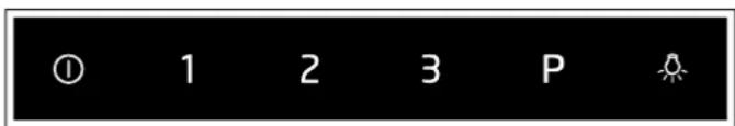
Symbol Explanation
| 1 Fan on/off |
| 1-3 Fan settings |
| P Intensive mode |
| Light on/off |
Setting the fan
Switching on
Touch the ① symbol.
Selecting the fan setting
Touch symbol 1, 2 or 3 to set a different fan setting.
Switching off
Touch the ① symbol.
Intensive setting
You can use the intensive setting if there is a large build-up of odours and fumes/vapours.
Switching on
Touch the P symbol.
Note: After approx. 6 minutes, the extractor hood automatically switches back to fan setting 3.
Switching off
If you want to end intensive mode before the preset time expires, touch the P symbol.
Lighting
The lighting can be switched on and off independently of the fan.
Touch the ☀ symbol.
Cleaning and maintenance

Risk of burns!
The appliance becomes hot during operation. Allow the appliance to cool down before cleaning.

Risk of electric shock!
Penetrating moisture may result in an electric shock. Clean the appliance using a damp cloth only. Before cleaning, pull out the mains plug or switch off the circuit breaker in the fuse box.

Risk of electric shock!
Do not use any high-pressure cleaners or steam cleaners, which can result in an electric shock.

Risk of injury!
Components inside the appliance may have sharp edges. Wear protective gloves.

Risk of injury!
Risk of trapping body parts when opening and closing the glass front. Do not reach into the area behind the glass panel, and keep your fingers away from the hinges.
Cleaning agents
To ensure that the different surfaces are not damaged by using the wrong cleaning product, follow the instructions in the table. Do not use any of the following:
■ Harsh or abrasive cleaning agents, e.g. scouring powder or liquid scouring cleaner,
■ Cleaning products with a high alcohol content,
■ Hard scouring pads or cleaning sponges,
■ Pressure washers or steam cleaners,
■ Cleaning products that dissolve limescale,
■ Aggressive all-purpose cleaning products,
■ Oven spray.
Note: Wash new sponge cloths thoroughly before use.
Note: Follow all instructions and warnings included with the cleaning products.
Area Cleaning products
| Stainless steel Hot soapy water: |
| Clean with a dish cloth and then dry with a soft cloth. |
| Clean stainless steel surfaces in the direction of the grain only. |
| Special stainless steel cleaning products are available from our after-sales service or from specialist retailers.Apply a very thin layer of the cleaning product with a soft cloth. |
| Painted surfaces Hot soapy water: | |
| Clean using a damp dish cloth and then dry with a soft cloth. | |
| Do not use stainless steel cleaner. | |
| Aluminium and plastic | Hot soapy water: |
| Clean with a soft cloth. | |
| Glass Glass cleaner: |
| Clean with a soft cloth. Do not use a glass scraper. |
| Controls Hot soapy water: |
| Clean using a damp dish cloth and then dry with a soft cloth. |
| Risk of electric shock caused by penetrating moisture. |
| Risk of damage to the electronics caused by penetrating moisture. Never clean controls with a wet cloth. |
| Do not use stainless steel cleaner. |
Removing metal grease filter
- Open the glass front slowly and fully. Hold the glass front in the centre when doing so, gripping it firmly.
- Open the lock and swing down the metal grease filter. When you do this, take hold of the metal grease filter from underneath with your other hand.
- Take the metal grease filter out of the holder.
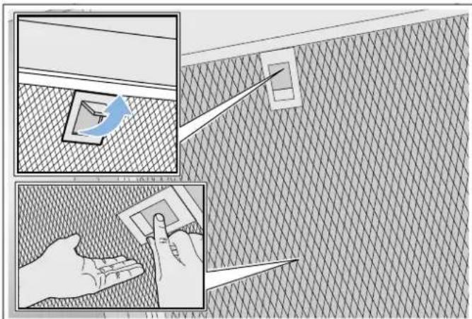
Notes
■ Fat may accumulate in the bottom of the metal grease filter.
- Hold the metal grease filter level to prevent grease from dripping out.
Cleaning the metal mesh grease filters
These instructions apply to several appliance variants. It is possible that individual features are described which do not apply to your appliance.
Risk of fire!
Fatty deposits in the grease filter may catch fire. Regularly clean the grease filter. Never operate the appliance without a grease filter.
Notes
■ Do not use aggressive, acidic or alkaline cleaning products.
■ We recommend cleaning the grease filters every 2 months.
■ When cleaning the metal grease filters, also clean the metal grease filter holder in the appliance using a damp cloth.
■ The metal grease filters can be cleaned in the dishwasher or by hand.
By hand:
Note. You can use a special degreaser to remove stubborn dirt. This can be ordered from the online shop.
■ Soak the metal grease filters in hot soapy water.
■ Clean the filters with a brush and then rinse them thoroughly.
■ Leave the metal grease filters to drain on an absorbent material.
In the dishwasher:
Note: Slight discolouration may occur if the metal grease filters are cleaned in the dishwasher. This discolouration has no effect on the performance of the metal grease filters.
■ Use normal domestic dishwashing detergents.
- Do not clean heavily soiled metal grease filters together with cookware.
■ Place the metal grease filters in the dishwasher, leaving plenty of space around them. Do not trap the metal grease filters.
■ Select a temperature of no more than 50 °C.
Trouble shooting
Malfunctions often have simple explanations. Please read the following notes before calling the after-sales service.
Risk of electric shock!
Incorrect repairs are dangerous. Repairs may only be carried out and damaged power cables replaced by one of our trained after-sales technicians. If the appliance is defective, unplug the appliance from the mains or switch off the circuit breaker in the fuse box. Contact the after-sales service.
Malfunction table
Problem Possible cause Solution
| The appliance does not work | The plug is not plugged in. | Connect the appliance to the electricity supply |
| Power cut Check whether other kitchen appliances are working | ||
| Faulty fuse Check in the fuse box to make sure that the fuse for the appliance is OK | ||
| The lighting does not work. | The LED lights are defective. | Call the after-sales service. |
| The button illumination does not work. | The control unit is faulty. | Call the after-sales service. |
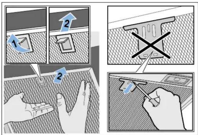
Installing the metal mesh grease filter
Risk of injury!
Components inside the appliance may have sharp edges. Wear protective gloves.
Note: Clean all accessible parts of the housing.
- Insert the metal grease filter and lock it in place. When you do this, take hold of the metal grease filter from underneath with your other hand.
Note: Make sure that the metal grease filter is positioned correctly. - If the metal grease filter has not been inserted correctly, open the lock and reinsert the metal grease filter correctly.
LED lights
Defective LED lights may be replaced by the manufacturer, their customer service or a qualified technician (electrician) only.
Risk of injury!
The light emitted by LED lights is very dazzling, and can damage the eyes (risk group 1). Do not look directly into the switched on LED lights for longer than 100 seconds.
Customer service
When calling us, please quote the product number (E no.) and the production number (FD no.) so that we can provide you with the correct advice. These numbers can be found on the rating plate on the top of the appliance.
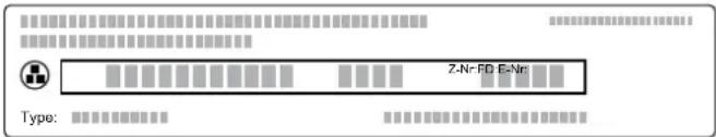
You can make a note of the numbers of your appliance and the telephone number of the after-sales service in the space below to save time should it be required.
E no. FD no.
After-sales serviceO
Please be aware that a visit by an after-sales engineer will be charged if a problem turns out to be the result of operator error, even during the warranty period.
Please find the contact data of all countries in the enclosed customer service list.
Rely on the professionalism of the manufacturer. You can therefore be sure that the repair is carried out by trained service technicians who carry original spare parts for your appliances.
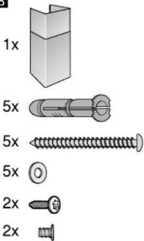
Accessories
(not included in the scope of delivery)
Note: These instructions apply to several appliance models. It may be the case that an optional accessory that is listed does not apply for your appliance.
Note: Observe the installation instructions in the accessory.
Accessories Order number
| Starter set for air recirculation mode (flat hood with chimney) | CZ51AFU0X0 |
| Easy-change filter for starter set | CZ51AFA0X |
| Starter set for air recirculation mode (flat hood without chimney) | CZ51AFT0X0 |
| Easy-change filter for starter set | CZ51AFA0X0 |
| Starter set for air recirculation mode (angled canopy hood with chimney) | CZ51AIU0X0 |
| Easy-change filter for starter set | CZ51AIA0X0 |
| Starter set for air recirculation mode (angled canopy hood without chimney) | CZ51AIT0X0 |
| Easy-change filter for starter set | CZ51AIA0X0 |
| Starter set for air recirculation mode with filter that can be regenerated (flat hood with chimney) | CZ51AFS0X0 |
| Starter set for air recirculation mode with filter that can be regenerated (angled canopy hood with chimney) | CZ51AIS0X0 |
| Starter set for air recirculation mode with filter that can be regenerated (flat hood without chimney) | CZ51AFR0X0 |
| Starter set for air recirculation mode with filter that can be regenerated (angled canopy hood without chimney) | CZ51AIR0X0 |
| CleanAir air recirculation module | CZ51AXC0N0 |
| Easy-change filter for CleanAir air recirculation module (cannot be regenerated) | CZ5170X1 |
| Easy-change filter for CleanAir air recirculation module (can be regenerated) | CZ50XXP0X0 |
INSTALLATION INSTRUCTIONS
■ This appliance is installed on the wall.
If the extractor hood is to be operated in exhaust-air mode, a flue duct must be fitted.
If the extractor hood is to be operated in air-recirculation mode, an optional accessory must be fitted. To do this, refer to the installation instructions provided. The flue duct does not need to be fitted for air-recirculation mode.
■ For additional optional accessories, refer to the installation instructions provided.
■ The surfaces of the appliance are sensitive. Avoid damaging them during installation.
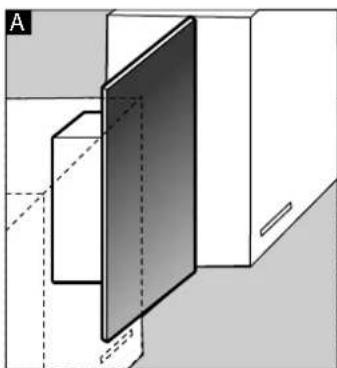
A
natural_image
Simple 3D diagram of a rectangular block with a vertical panel on top (no text or symbols)B

natural_image
Simple 3D geometric diagram showing a cube intersected by a plane, no text or symbols presentA|B
natural_image
Exploded view diagram of mechanical parts including a bracket, bracket, and housing (no text or labels)Note: We recommend fitting the appliance such that the lower edge of the glass screen is in line with the lower edges of the adjacent wall-hung cabinets. Make sure that the specified safety clearances from the hob are complied with.
A
B
natural_image
3D diagram of a door opening with dashed lines indicating hidden edges, no text or symbols present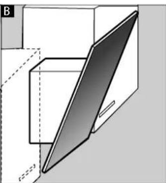
natural_image
3D diagram of a geometric structure with a shaded triangular plane and dashed lines, no text or symbols present⚠️ Important safety information
Read these instructions carefully. Only then will you be able to operate your appliance safely and correctly. Retain the instruction manual and installation instructions for future use or for subsequent owners.
Check the appliance for damage after unpacking it. Do not connect the appliance if it has been damaged in transport.
The appliance can only be used safely if it is correctly installed according to the safety instructions. The installer is responsible for ensuring that the appliance works perfectly at its installation location.
The surfaces of the appliance are easily damaged. Avoid damaging them during installation.
The width of the extractor hood must correspond at least with the width of the hob.
For the installation, observe the currently valid building regulations and the regulations of the local electricity and gas suppliers.
Risk of fire!
- Fatty deposits in the grease filter may catch fire. The specified safety clearances must be complied with in order to prevent a build-up of heat. Refer to the information provided for your cooker. If gas and electric hobs are being operated together, the largest specified clearance applies.
- Grease deposits in the grease filter may catch fire. Never work with naked flames close to the appliance (e.g. flambéing). Do not install the appliance near a heat-producing appliance for solid fuel (e.g. wood or coal) unless a closed, non-removable cover is available. There must be no flying sparks.
When conveying the exhaust air, official and legal regulations (e.g. state building regulations) must be followed.
Risk of death!
Risk of poisoning from flue gases that are drawn back in. The exhaust air must not be conveyed into a functioning smoke or exhaust gas flue or into a shaft which is used to ventilate installation rooms that contain heating appliances. If the exhaust air is to be conveyed into a non-functioning smoke or exhaust gas flue, you must obtain the consent of the heating engineer responsible.
Danger of death!
Risk of poisoning from flue gases that are drawn back in.
Always ensure adequate fresh air in the room if the appliance is being operated in exhaust air mode at the same time as room air-dependent heat-producing appliance is being operated.
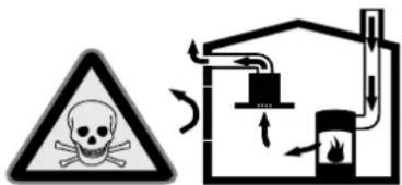
Room air-dependent heat-producing appliances (e.g. gas, oil, wood or coal-operated heaters, continuous flow heaters or water heaters) obtain combustion air from the room in which they are installed and discharge the exhaust gases into the open air through an exhaust gas system (e.g. a chimney).
In combination with an activated vapour extractor hood, room air is extracted from the kitchen and neighbouring rooms - a partial vacuum is produced if not enough fresh air is supplied. Toxic gases from the chimney or the extraction shaft are sucked back into the living space.
■ Adequate incoming air must therefore always be ensured.
■ An incoming/exhaust air wall box alone will not ensure compliance with the limit. Safe operation is possible only when the partial vacuum in the place where the heat-producing appliance is installed does not exceed 4 Pa (0.04 mbar). This can be achieved when the air needed for combustion is able to enter through openings that cannot be sealed, for example in doors, windows, incoming/exhaust air wall boxes or by other technical means.
natural_image
Simple line drawing of a house with a checkmark and airflow indicators (no text or symbols)In any case, consult your responsible Master Chimney Sweep. He is able to assess the house's entire ventilation setup and will suggest the suitable ventilation measures to you.
Unrestricted operation is possible if the vapour extractor hood is operated exclusively in the circulating-air mode.
Danger of death!
Risk of poisoning from flue gases that are drawn back in. If installing a ventilation system in a room with a heat-producing appliance connected to a chimney/flue, the electricity supply to the hood must be equipped with a suitable safety switch.
Risk of injury!
■ Components inside the appliance may have sharp edges. Wear protective gloves.
■ The appliance may fall down if it has not been properly fastened in place. All fastening components must be fixed firmly and securely.
■ The appliance is heavy. To move the appliance, 2 people are required. Use only suitable tools and equipment.
■ Changes to the electrical or mechanical assembly are dangerous and may lead to malfunctions. Do not make any changes to the electrical or mechanical assembly.
Hazard due to magnetism!
Permanent magnets are inserted in the appliance front. They may affect electronic implants, e.g. heart pacemakers or insulin pumps. Wearers of electronic implants must stay at least 10 cm away from the appliance front.
Risk of electric shock!
■ Components inside the appliance may have sharp edges. These may damage the connecting cable. Do not kink or pinch the connecting cable during installation.
- It must always be possible to disconnect the appliance from the power supply. The appliance must only be connected to a protective contact socket that has been correctly installed. If the plug can no longer be reached after installation, an energy-isolating device in the phases must be provided in the permanent electrical installation in accordance with the installation regulations. The permanent electrical installation must only be wired by a professional electrician. We recommend installing a residual-current circuit breaker (RCCB) in the appliance's power supply circuit.
Risk of electric shock!
Incorrect repairs are dangerous. Repairs may only be carried out and damaged power cables replaced by one of our trained after-sales technicians. If the appliance is defective, unplug the appliance from the mains or switch off the circuit breaker in the fuse box. Contact the after-sales service.
Danger of suffocation!
Packaging material is dangerous to children. Never allow children to play with packaging material.
General information
Checking the wall
■ The wall must be level, vertical and adequately load-bearing.
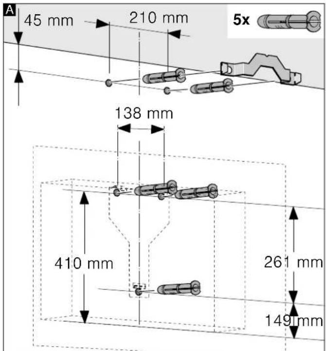
■ The depth of the bore holes must be the same length as the screws. The wall plugs must have a secure grip.
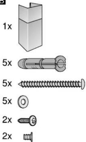
The enclosed screws and wall plugs are suitable for solid brickwork. Suitable fasteners must be used for other structures (e.g. plasterboard, porous concrete, poroton bricks).
■ The maximum weight of the extractor hood is 40 kg.
Electrical connection

Risk of electric shock!
Components inside the appliance may have sharp edges. These may damage the connecting cable. Do not kink or pinch the connecting cable during installation.
The required connection information can be found on the rating plate on the top of the appliance.
Length of the cable: approx. 1.30 m
This appliance complies with the EC interference suppression regulations.

Risk of electric shock!
It must always be possible to disconnect the appliance from the power supply. The appliance must only be connected to a protective contact socket that has been correctly installed. If the plug can no longer be reached after installation, an energy-isolating device in the phases must be provided in the permanent electrical installation in accordance with the installation regulations. The permanent electrical installation must only be wired by a professional electrician. We recommend installing a residual-current circuit breaker (RCCB) in the appliance's power supply circuit.
Installation
Preparing for installation
Caution!
Ensure that there are no electrical wires, gas pipes or water pipes in the area where holes are to be drilled.
If the extractor hood is to be operated in exhaust-air mode, a flue duct must be fitted.
If the extractor hood is to be operated in air-recirculation mode, an optional accessory must be fitted. To do this, refer to the installation instructions provided. The flue duct does not need to be fitted for air-recirculation mode.
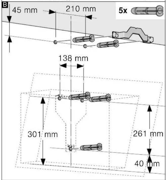
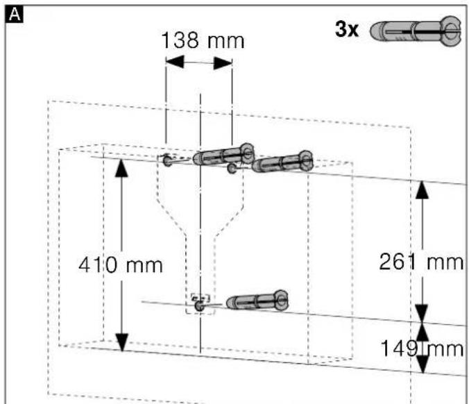
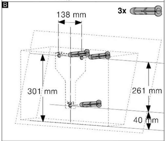
- Determine where the extractor hood should be positioned and lightly mark where the lower edge of the appliance should be on the wall. Determine where the middle should be based on the hob.
Note: We recommend fitting the extractor hood such that the lower edge of the glass screen is in line with the lower edges of the adjacent wall-hung cabinets. Make sure that the specified safety clearances from the hob are complied with.
-
Place the template against the line drawn on the wall and fasten it in place. Mark where the screws should be inserted. To fit the flue duct, the template must be cut along the marked cut line.
-
Drill 8 mm diameter holes to a depth of 80 mm for fastening the appliance, remove the template and press in the wall plugs flush with the wall.
Fitting with a flue duct Fitting without a flue duct
Installation
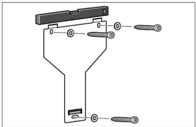
Screw in the mounting supports for the extractor hood until they are hand-tight, use a spirit level to level the appliance and then screw the mounting supports in fully.
Wall-mounting the appliance and levelling it
- First remove the protective film from the back of the appliance and, following installation, remove the rest of the film.
- When mounting the appliance, ensure that it engages properly with the mounting supports.
- If required, the appliance can be moved to the right or to the left.
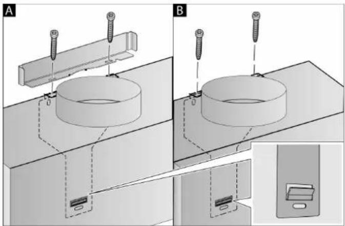
- Firmly tighten the screws for the mounting supports. Hold the bracket firmly when doing so. A
natural_image
Technical illustration of two mechanical assembly steps (A and B) showing screw installation on a plate, with inset view of a device component (no text or symbols)- If no duct is to be fitted, screw in the two locking screws without the bracket. B
Connecting the pipes
If the extractor hood is to be operated in exhaust-air mode, the pipes must be connected. If the extractor hood is to be operated in air-recirculation mode, an optional accessory must be fitted. To do this, refer to the installation instructions provided.
Note: If an aluminium pipe is being used, smooth the connection area beforehand.
Exhaust air pipe, dia. 150 mm (recommended size)
Fit the exhaust air pipe directly to the air-pipe connector and seal the joint.
Exhaust air pipe, dia. 120 mm
- Fit the reducing connector directly to the air-pipe connector.
- Attach the exhaust air pipe to the reducing connector.
- Use suitable means to seal both joints.
Attaching the flue duct
If the extractor hood is to be operated in exhaust-air mode, a flue duct must be fitted.
The flue duct does not need to be fitted for air-recirculation mode.
Risk of injury!
From sharp edges during installation. Always wear protective gloves while installing the appliance.
Risk of electric shock!
Components inside the appliance may have sharp edges. These may damage the connecting cable. Do not kink or pinch the connecting cable during installation.
- Separate the flue duct sections by removing the adhesive tape.
- Remove the pieces of protective film from both flue duct sections.
- Push one flue duct section into the other.
Notes
■ To prevent scratches, lay paper over the edges of the outer flue duct section to protect the surface.
■ The slots of the inner flue duct section point downwards.
-
Place flue ducts sections on the appliance.
-
Slide the inner flue duct section upwards, attach it to the left and right sides of the retaining bracket, and then slide it down to engage it. A
- Screw the flue duct section to the sides of the retaining bracket using two screws. B
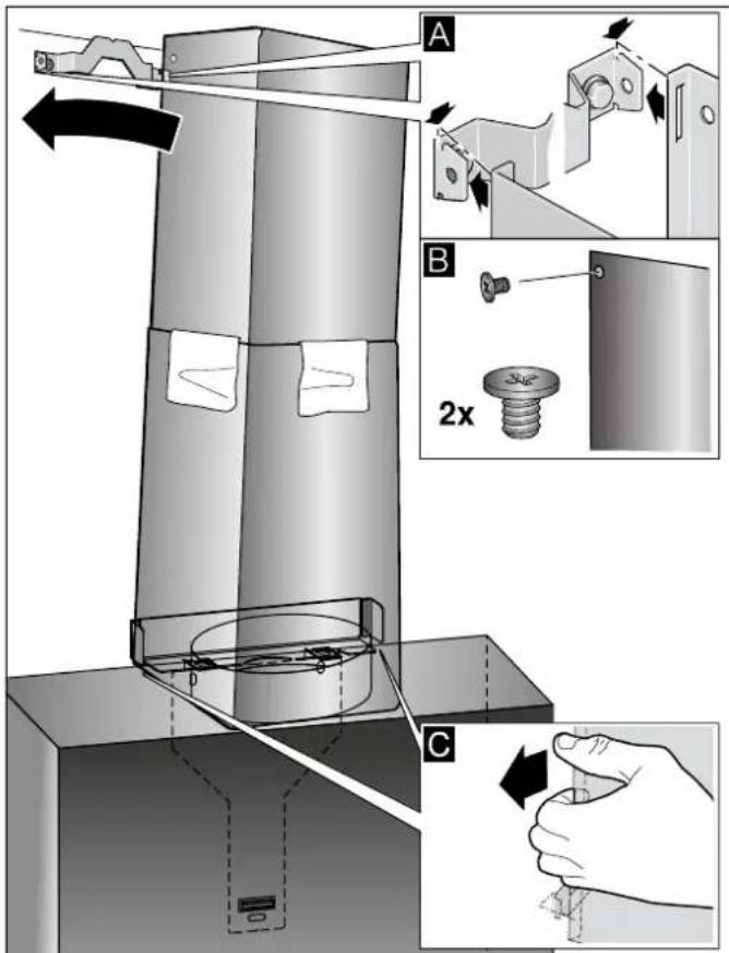
- Clip the lower flue duct section in at the retaining bracket. The connection cable must not be damaged.
Note: If an air-recirculation optional accessory has been fitted and the extractor hood is to be operated without a flue duct, the cable must be wound onto the connector.

Table des matières
NOTICE D'UTILISATION .... 30
natural_image
Simple line drawing of a gas stove with a checkmark and fire symbol (no text or labels)natural_image
Illustration showing two steps: surface texture inspection and hand holding a small object, with no visible text or symbols.Remarques
natural_image
Simple 3D diagram of a rectangular block with a vertical plane on top (no text or symbols)B
natural_image
Simple 3D geometric diagram showing a cube and a shaded plane (no text or symbols)A B
natural_image
Exploded view diagram of mechanical parts including a bracket, bracket, and housing (no text or symbols)natural_image
Two 3D architectural diagrams showing exterior and interior views of a building, with no visible text or symbols.natural_image
Simple line drawing of a checkmark and a schematic diagram of a gas stove (no text or symbols)natural_image
Technical diagram of a mechanical clamp or bracket assembly with threaded pins and mounting holes (no text or labels)natural_image
Technical illustration of two mechanical assembly steps (A and B) showing screw installation on a cylindrical component, with inset view of a device (no text or symbols)natural_image
Simple line drawing of a house with fire and steam, alongside a checkmark (no text or symbols)Symbool Toelichting
natural_image
Diagram showing two steps of installing or maintaining a grid-patterned surface, with no visible text or symbols.Aanwijzingen
natural_image
Simple 3D diagram of a rectangular block connected to a vertical gradient panel (no text or symbols)B
natural_image
Simple 3D geometric diagram showing a cube intersected by a plane, no text or symbols presentA B
natural_image
Exploded view diagram of mechanical parts including a bracket, bracket, and housing (no text or symbols)A
B
natural_image
Two 3D geometric diagrams labeled A and B showing a rectangular prism with a shaded panel, no text or symbols present.natural_image
Simple line drawing of a house with a checkmark and airflow indicators (no text or symbols)natural_image
Technical diagram of a mechanical clamp or bracket assembly with threaded pins and mounting holes (no text or labels)natural_image
Technical illustration of two mechanical assembly setups (A and B) showing bolted components and a close-up view of a device with a labeled component (no text or symbols present)
- Hinweise
- Störungen, was tun?
- INSTRUCTION MANUAL
- Intended use
- ⚠️ Important safety information
- Danger of suffocation!
- Danger of death!
- Risk of fire!
- Risk of burns!
- Risk of injury!
- Hazard due to magnetism!
- Risk of electric shock!
- Causes of damage
- Caution!
- Environmental protection
- Saving energy
- Environmentally-friendly disposal
- Operating modes
- Exhaust air mode
- Circulating-air mode
- Operating the appliance
- Control panel
- Setting the fan
- Switching on
- Selecting the fan setting
- Switching off
- Intensive setting
- Lighting
- Cleaning and maintenance
- Cleaning agents
- Removing metal grease filter
- Notes
- Cleaning the metal mesh grease filters
- By hand:
- In the dishwasher:
- Trouble shooting
- Malfunction table
- Installing the metal mesh grease filter
- LED lights
- Customer service
- E no. FD no.
- After-sales serviceO
- Accessories
- INSTALLATION INSTRUCTIONS
- Risk of death!
- General information
- Checking the wall
- Electrical connection
- Length of the cable: approx. 1.30 m
- Installation
- Preparing for installation
- Wall-mounting the appliance and levelling it
- Connecting the pipes
- Exhaust air pipe, dia. 150 mm (recommended size)
- Exhaust air pipe, dia. 120 mm
- Attaching the flue duct
- Table des matières
- Remarques
- Aanwijzingen
Brand : CONSTRUCTA
Model : CD686860
Category : Basket