
BHI1043X - Basket BRANDT - Free user manual and instructions
Find the device manual for free BHI1043X BRANDT in PDF.
| Brand | Brandt |
| Model | BHI1043X |
| Product type | Kitchen hood |
| Installation type | Ceiling mount (recirculation version) |
| Minimum distance from cooking surface | 50 cm (electric cooker), 65 cm (gas or mixed) |
| Power supply | 230 V / 50 Hz (check the label) |
| Suction power | 3 speeds (minimum, average, maximum) |
| Lighting | LED (not user-replaceable) |
| Grease filter | Metallic, dishwasher safe (monthly) |
| Activated carbon filter | Optional, cleanable or replaceable (every 3 years) |
| External cleaning | Damp cloth and neutral detergent (no abrasive products) |
| Safety | Automatic shut-off in case of problem, flame protection |
| Electrical connection | By compliant circuit breaker, power cable not modifiable |
| Material | Stainless steel (estimate) |
| Duct height | Not specified (standard adaptable height) |
| Weight | Not specified (heavy, requires 2 people for installation) |
| Dimensions | Not specified (standard model likely 60 cm width) |
| Noise level | Not specified (estimate: 55-65 dB depending on speed) |
| After-sales service | 09 69 39 34 34 (France, toll-free + call charges) |
| Warranty | Not specified (minimum legal warranty of 2 years) |
Frequently Asked Questions - BHI1043X BRANDT
User questions about BHI1043X BRANDT
0 question about this device. Answer the ones you know or ask your own.
Ask a new question about this device
Download the instructions for your Basket in PDF format for free! Find your manual BHI1043X - BRANDT and take your electronic device back in hand. On this page are published all the documents necessary for the use of your device. BHI1043X by BRANDT.
USER MANUAL BHI1043X BRANDT
EN INSTRUCTION ON MOUNTING AND USE
RELATIONS CONSOMMATEURS France
You have just acquired a BRANDT hood, and we would like to thank you.
Our research teams have created this new generation of appliances for you. Their quality, design, features and technological advances make them exceptional products, and reveal our unique know-how.
Your new BRANDT hood will blend harmoniously into your kitchen and will perfectly combine extraction performance and ease of use. We wanted to offer you a product of excellence.
In the BRANDT product range, you will also find a wide choice of hobs, ovens, microwaves, dishwashers, cookers, fridges, freezers, that you can coordinate with your new BRANDT hood.
Visit our website www.brandt.com, where you will find our latest innovations as well as useful and complementary information.
BRANDT
As part of our commitment to constantly improving our products, we reserve the right to make changes to them based on technical advances to their technical and functional features and appearance.

Warning : Before installing and using your appliance, please carefully read this Guide to Installation and Use, which will allow you to quickly familiarise yourself with its operation.
www.brandt.com

Contents
EN - Safety and important precautions 31
Instruction on mounting and use 33
Use....33
Installation 33
Electrical connection....33
Mounting 33
Operation 33
Maintenance 34
Cleaning 34
Grease filter....34
Charcoal filter 34
Replacing lamps....34
Troubleshooting....35
After-sales service 35
These instructions are also available on the web site.
Please take heed of this advice when installing and using your appliance. These instructions are intended to protect your safety and the safety of others. Keep this manual with your appliance. If you sell or give the appliance to anyone else, make sure that you also give them this manual.
- In order to constantly improve our products, we reserve the right to make changes to their technical, functional or aesthetic characteristics in line with technological progress.
- Make a note of the references of your appliance on the "Consumer Service" page so that you can readily find them in the future.
Important precautions
- This appliance is designed for use by consumers at home. Do not use it for commercial or industrial purposes or for any other purpose for which it is not intended.
- Unpack the appliance as soon as you receive it. Check its general appearance. Make a note of any reservations on the delivery slip and keep a copy.
- This appliance can be used by children aged from 8 years and above and persons with reduced physical, sensory or mental capabilities or lack of experience and knowledge if they have been given supervision or instruction concerning use of the appliance in a safe way and understand the hazards involved.
- Children shall not be allowed to tamper with the controls and shall be supervised in order not to play with the appliance.
- Cleaning and user maintenance shall not be made by children without supervision.
- Caution: The accessible parts of this appliance may become hot when used with cooking equipment.
Electrical risks
- All the power supply circuits must be disconnected before touching the connection terminals. If the power cord is damaged, it must be replaced by the manufacturer, its after-sales service or a similarly qualified person in order to avoid any danger.
- The product is meant for connecting directly to the mains supply, therefore apply a bipolar switch that ensures complete disconnection from the mains in the conditions of category III over-voltage, in accordance with the wiring rules.
- Do not change or attempt to change the characteristics of this appliance. Doing so can be dangerous.
- The appliance must only be repaired by an approved specialist.
• Always disconnect the hood before cleaning or maintaining it.
- Never use steam or high-pressure tools to clean your appliance (for the purposes of electrical safety).
- Warning: Failure to install the screws or fixing device in accordance with these instructions may result in electrical hazards.
Risk of asphyxiation
- The regulations applying to the evacuation of air must be obeyed. The air must not be sent into a duct used to evacuate fumes from appliances that use gas or other fuels (this does not apply to appliances that only emit air into the room).
- The room must be suitably ventilated when the range hood is used at the same time as appliances that use gas or other fuels (this does not apply to appliances that only emit air into the room).
- Range hoods and other cooking fume extractors may adversely affect the safe operation of appliances burning gas or other fuels (including those in other rooms) due to back flow of combustion gases. These gases can potentially result in carbon monoxide poisoning. After installation of a range hood or other cooking fume extractor, the operation of flued gas appliances should be tested by a competent person to ensure that back flow of combustion gases does not occur
Risk of fire
- It is forbidden to flame food or to turn on gas rings that are not covered by a cooking recipient beneath the hood, as the flames may by sucked in and damage the appliance.
- Keep a constant eye on fryers used beneath the hood. When heated to very high temperatures, oil and fat can catch fire.
- Clean the appliance and replace the filters at the recommended frequency. Accumulated deposits of grease can cause a fire.
- It is forbidden to use the hood above a fuel fire (wood, coal, etc.).
Instruction on mounting and use
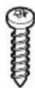
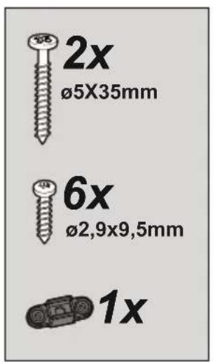
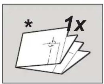
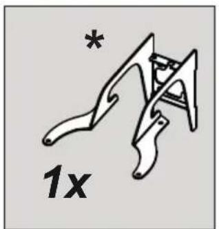
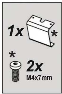
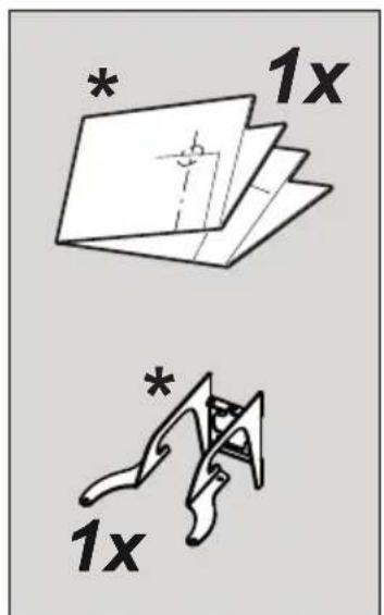
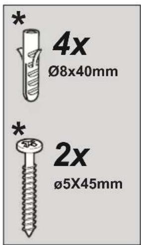
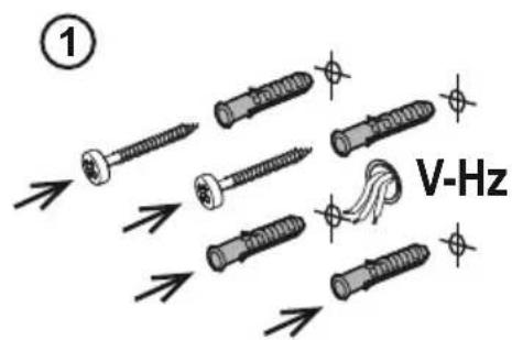
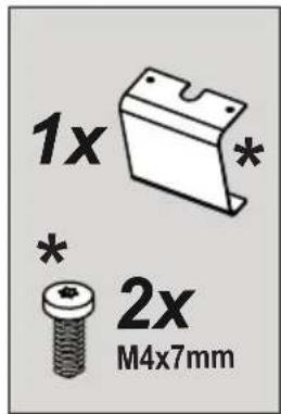
Note: the parts marked with the symbol "(*)" are optional accessories supplied only with some models or otherwise not supplied, but available for purchase.
Use
The hood has been made for use in the internal recirculating filtering version.
Cooking fumes and steam are aspirated inside the hood, filtered and cleaned, passing through the fat filters and the carbon filters that MUST be supplied with the hood.
Installation
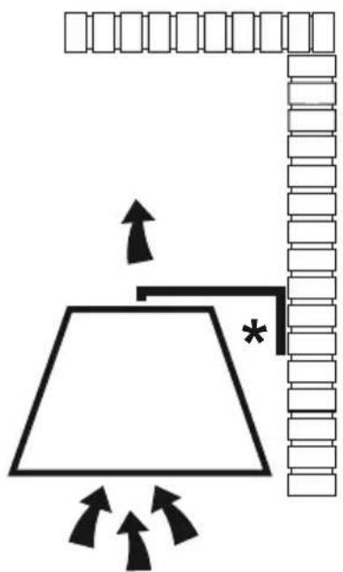
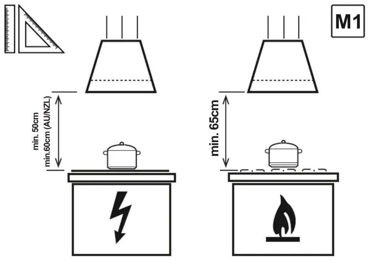
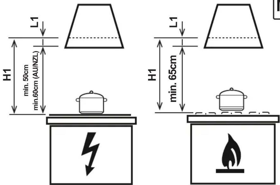
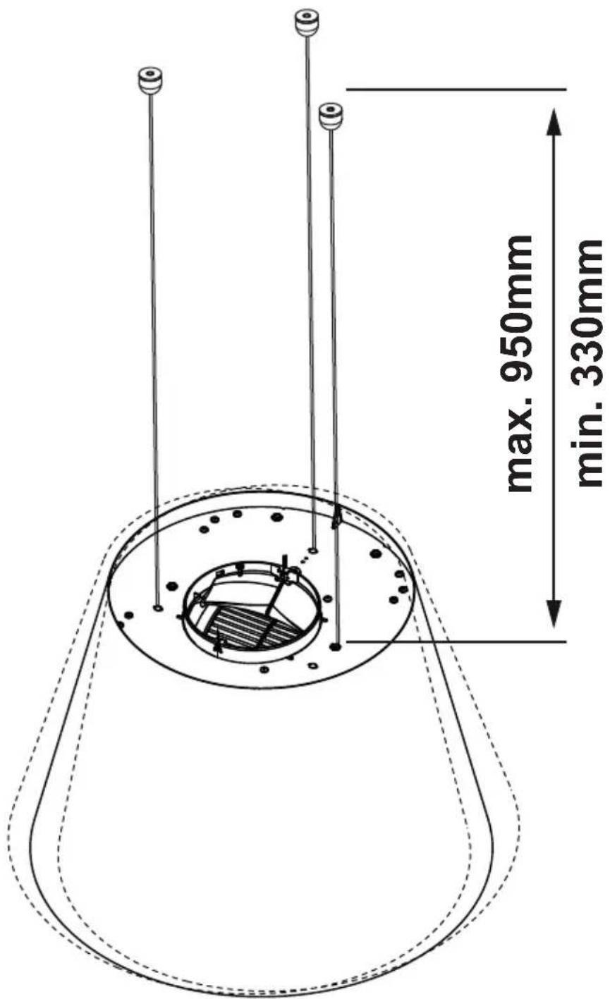
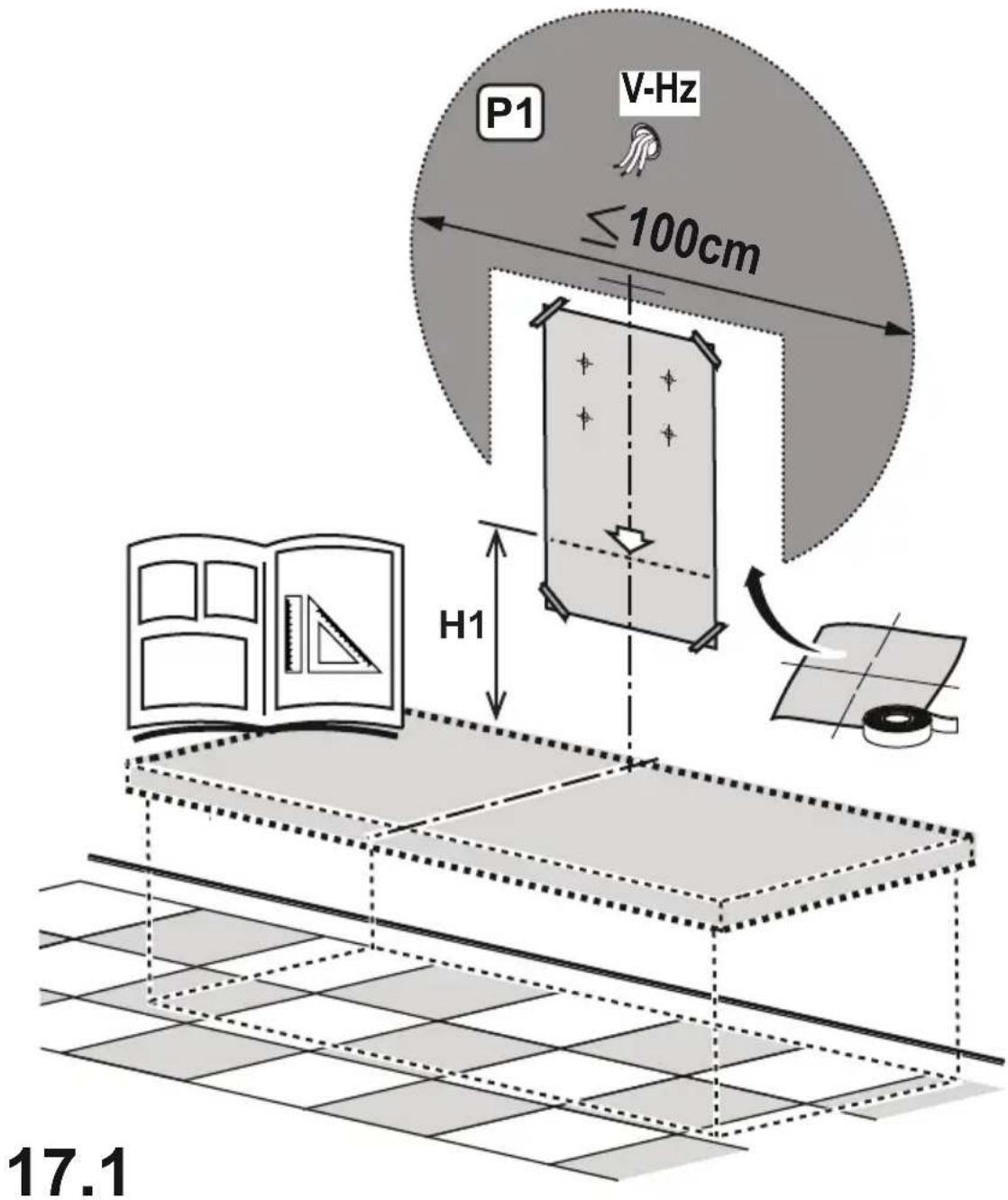
- The minimum distance between the supporting surface for the cooking equipment on the hob and the lowest part of the range hood must not be less than 50cm (not less than 60 cm only for Australia and New Zealand) from electric cookers and 65cm from gas or mixed cookers.
If the instructions for installation for the gas hob specify a greater distance, this must be adhered to.

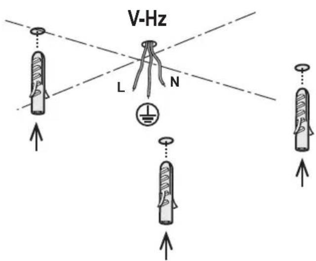
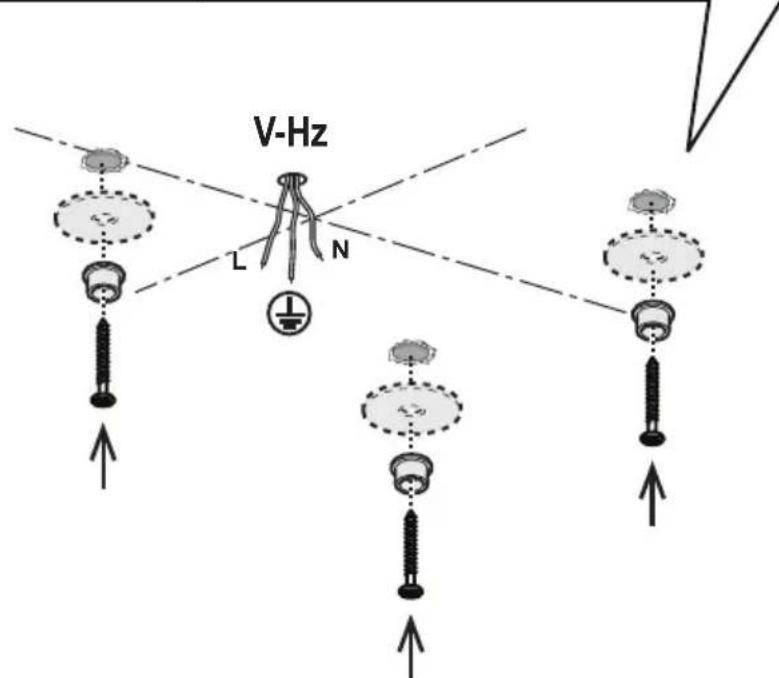
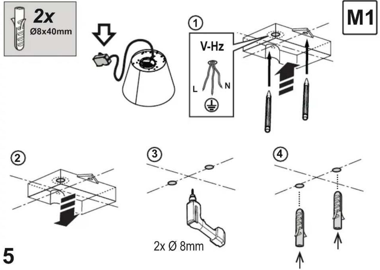
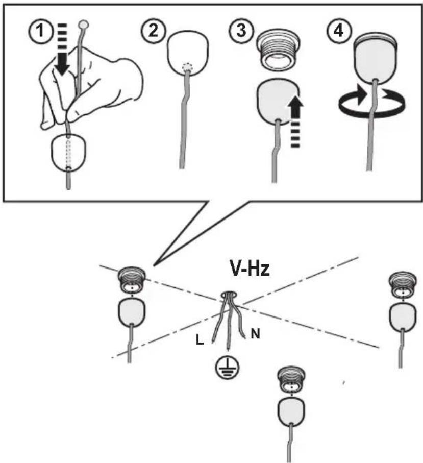
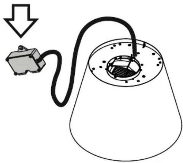
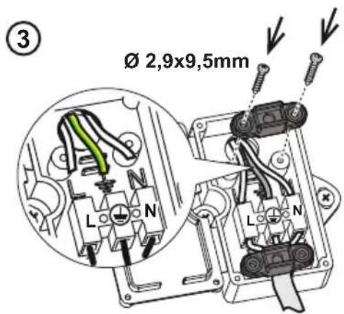
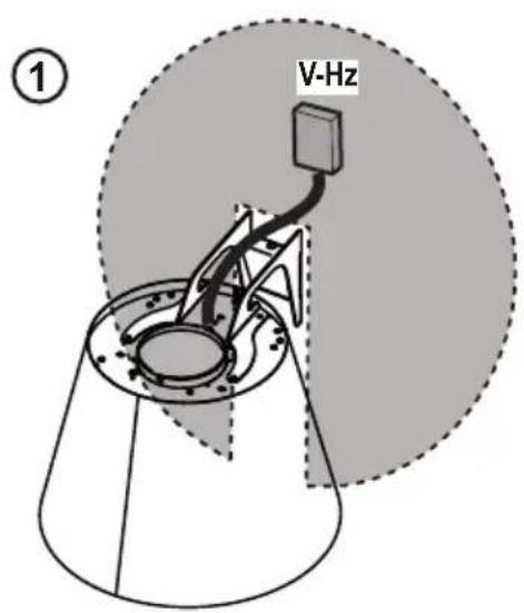
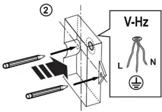
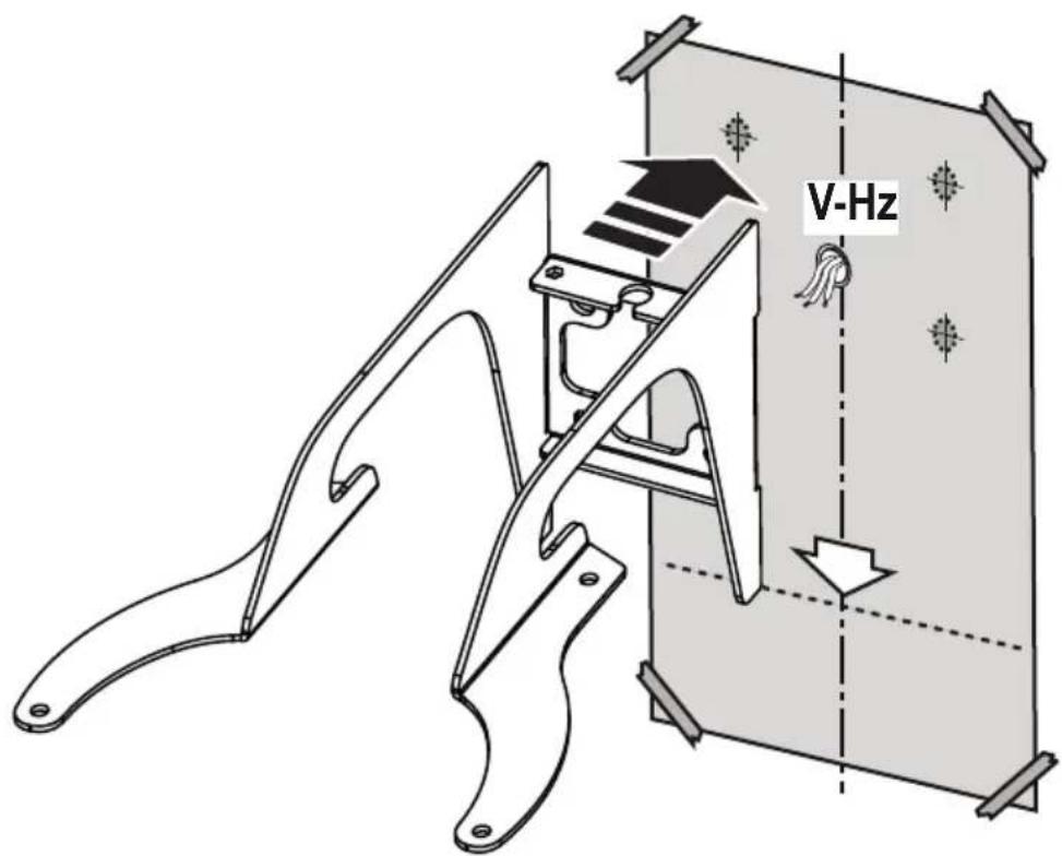
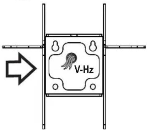
Electrical connection
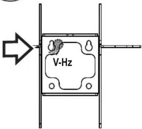
The main tension must correspond to the tension shown on the characteristic label situated inside the hood.
Warning! Changing the interconnection cable must be carried out by the authorised technical assistance service.
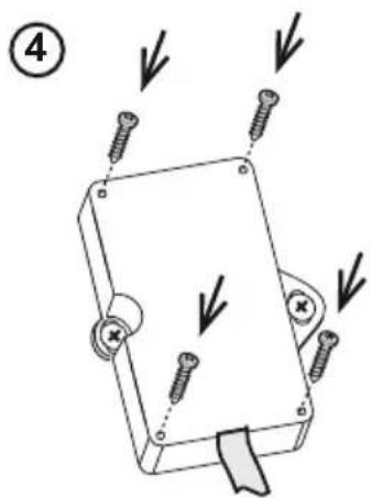
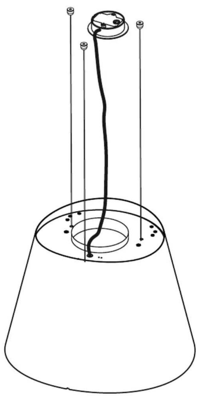
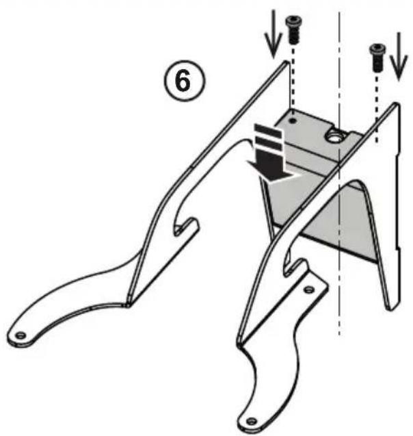
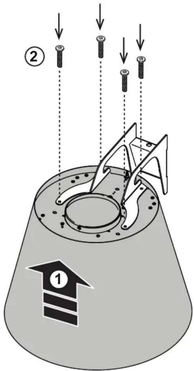
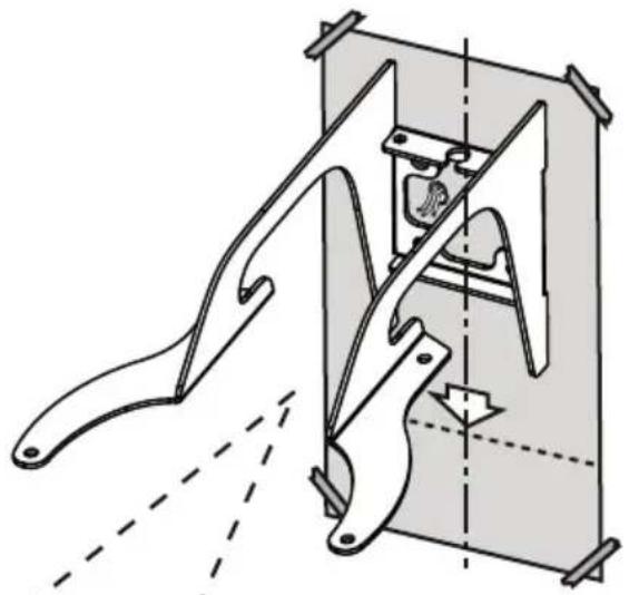
Mounting
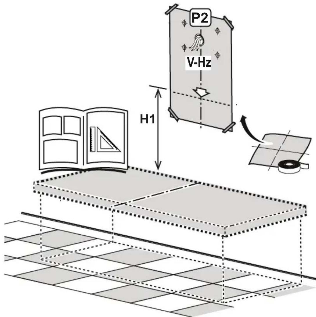
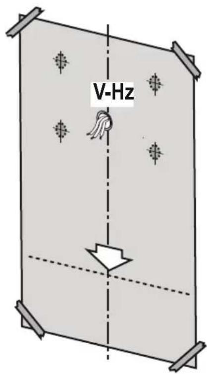
Before beginning installation:
- Check that the product purchased is of a suitable size for the chosen installation area.
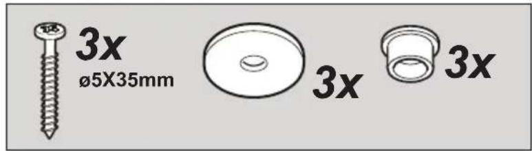
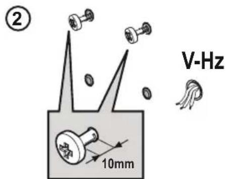
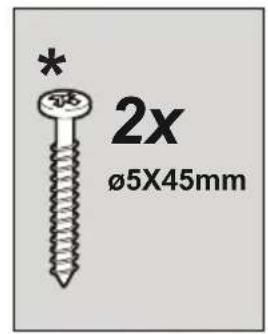
- Check (for transport reasons) that there is no other supplied material inside the hood (e.g. packets with screws (*), guarantees (*), etc.), eventually removing them and keeping them.
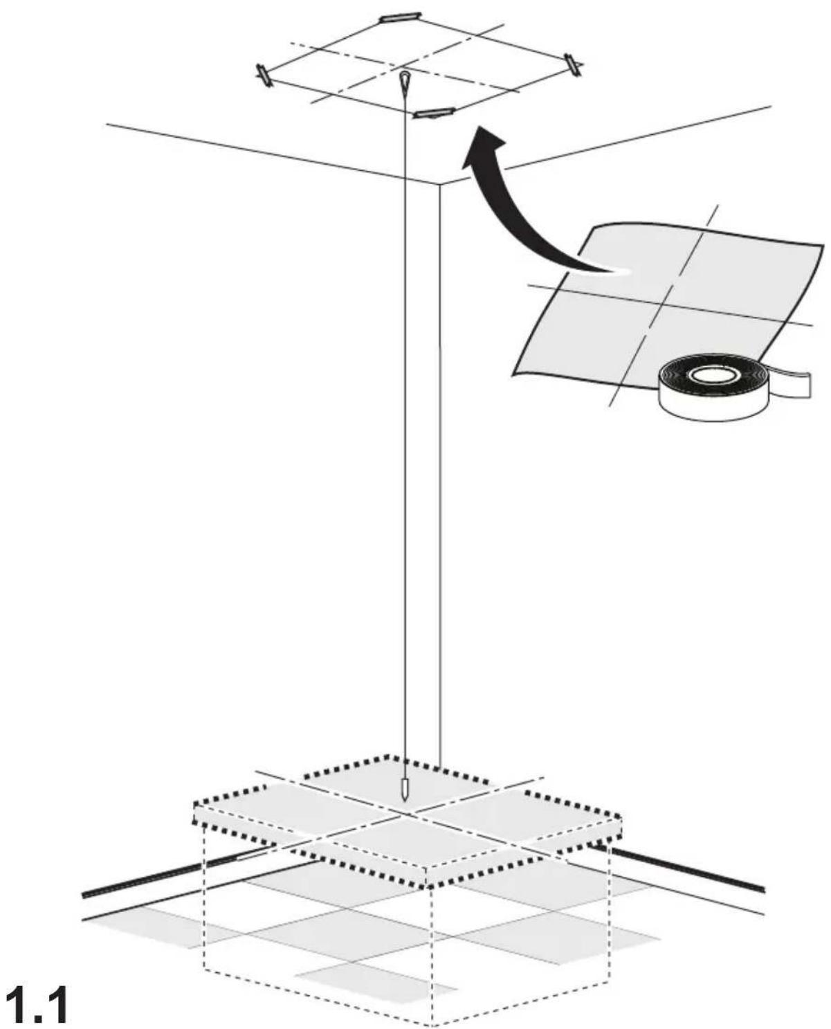
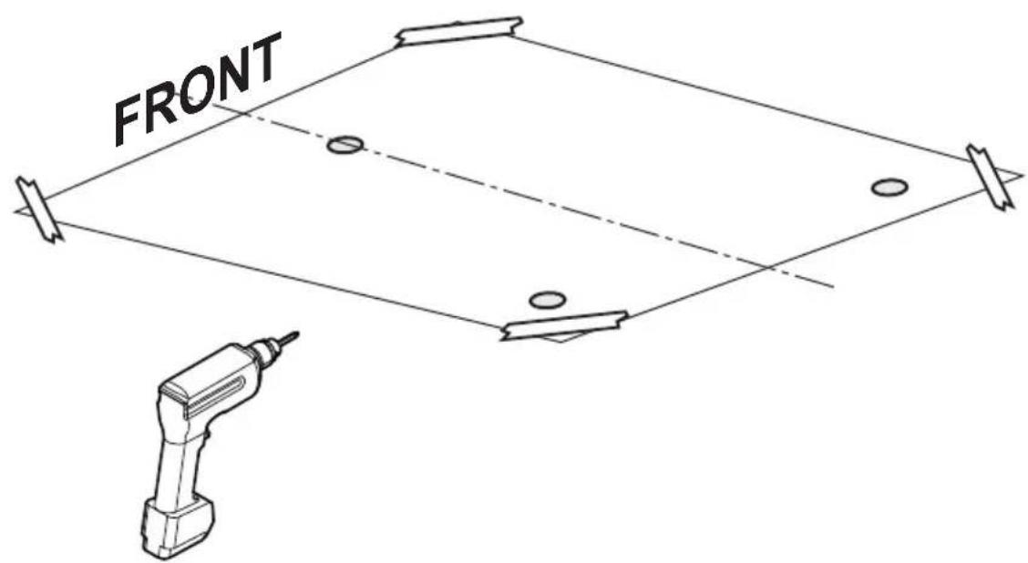
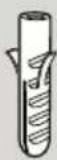
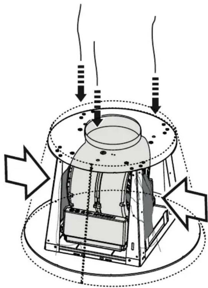
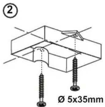
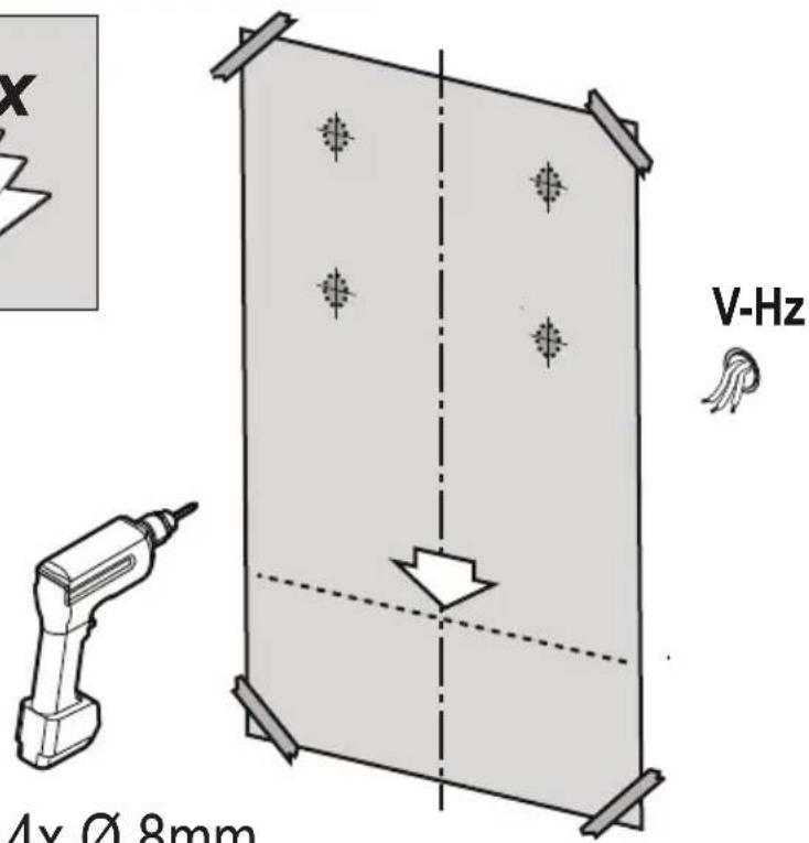
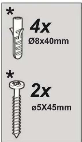
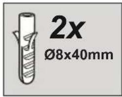
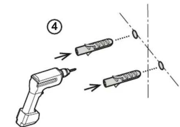
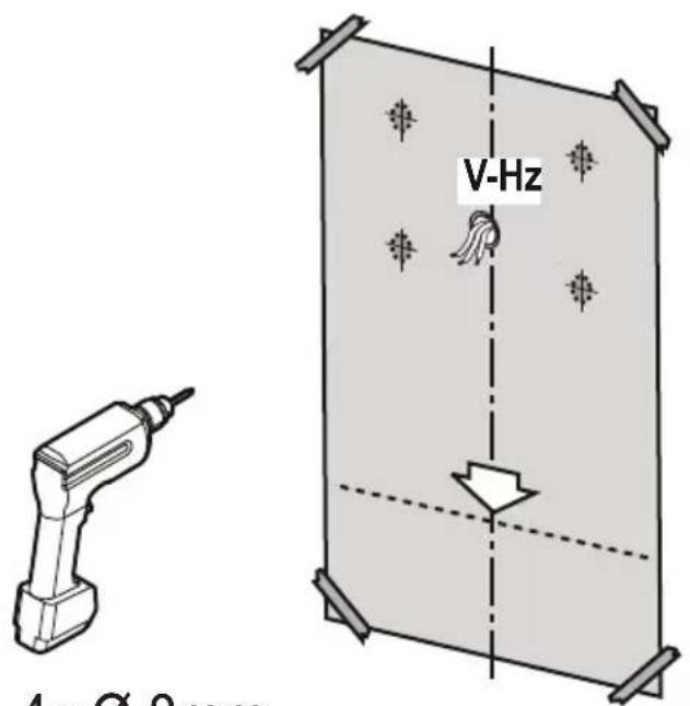
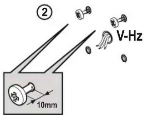
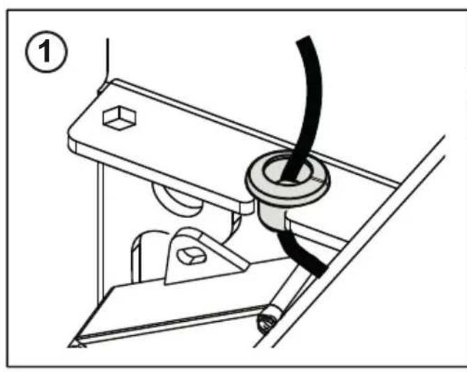
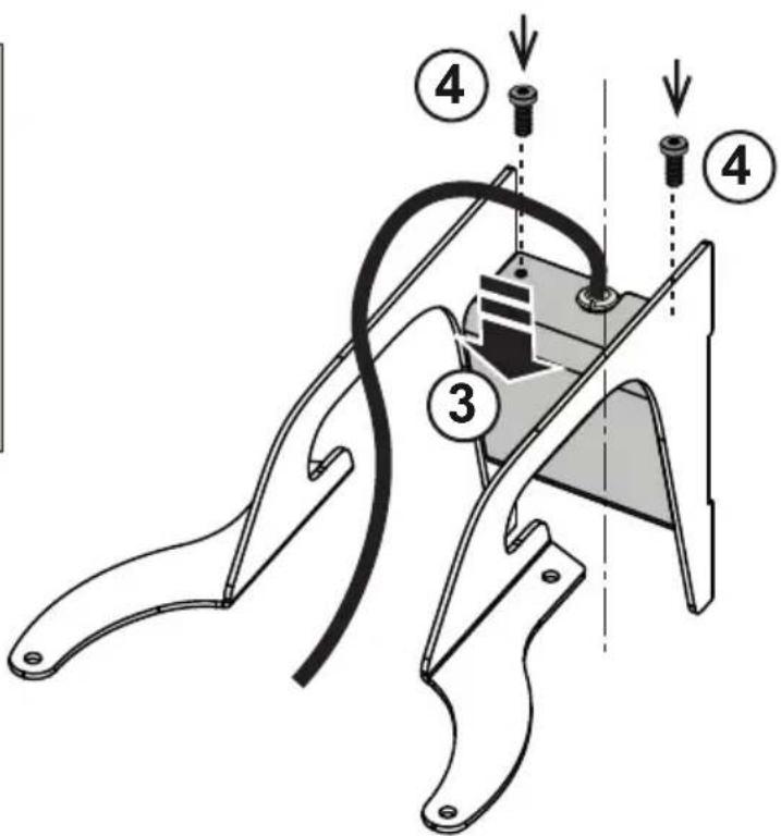
Expansion wall plugs are provided to secure the hood to most types of walls/ceilings. However, a qualified technician must verify suitability of the materials in accordance with the type of wall/ceiling. The wall/ceiling must be strong enough to take the weight of the hood.
Do not tile, grout or silicone this appliance to the wall. Surface mounting only.
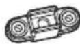
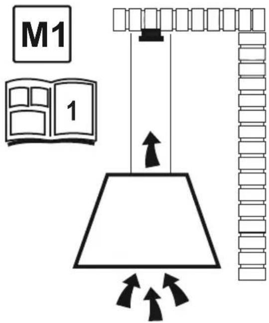
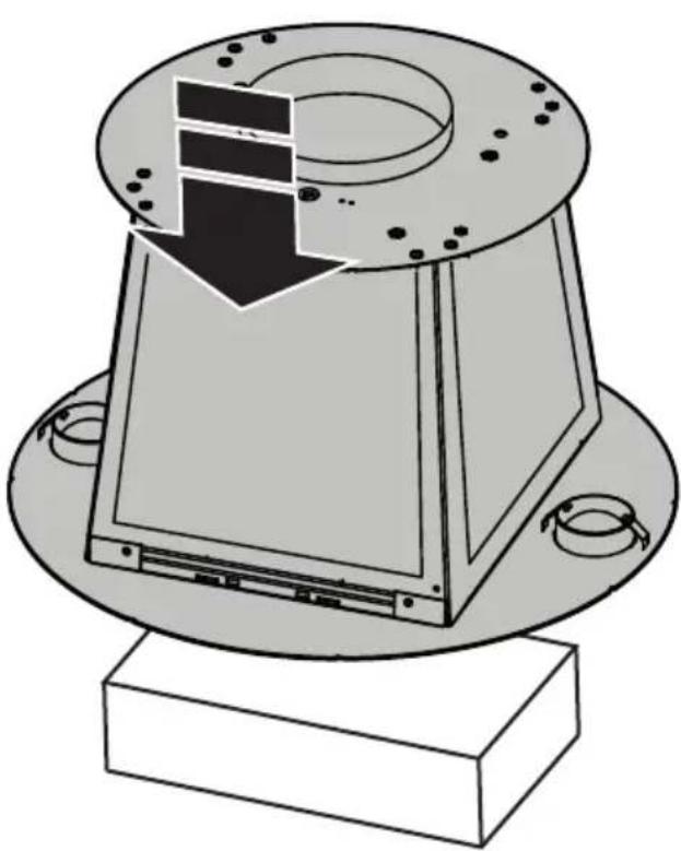
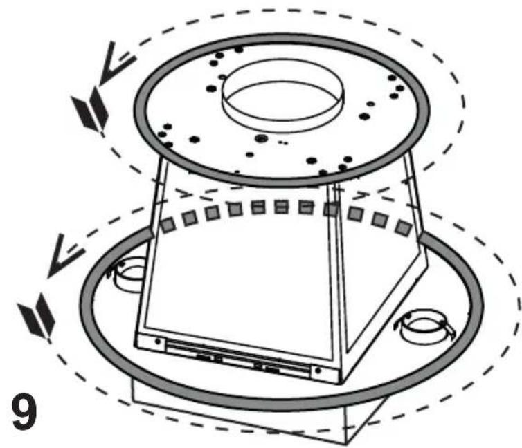
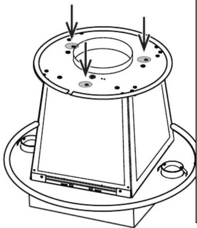
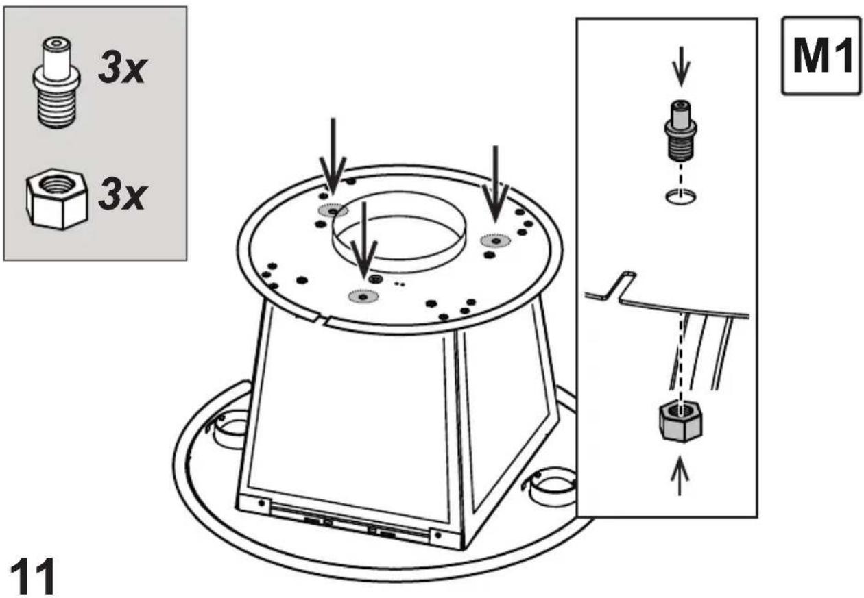
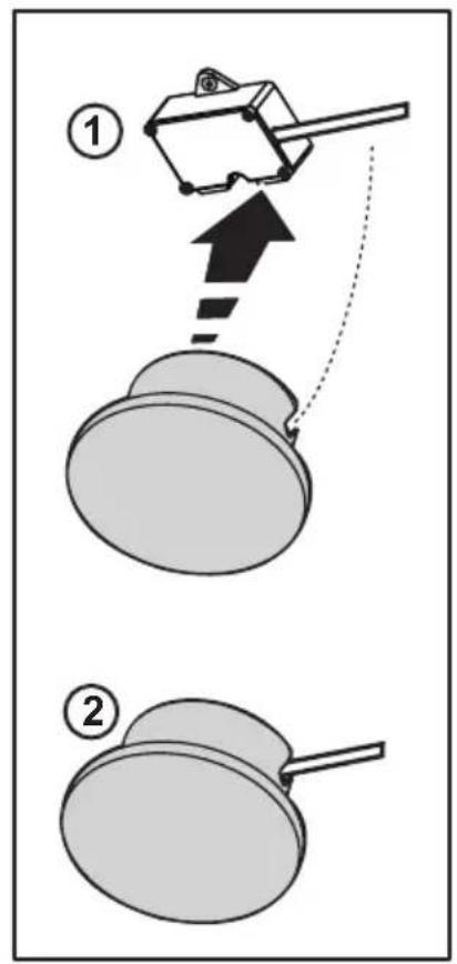
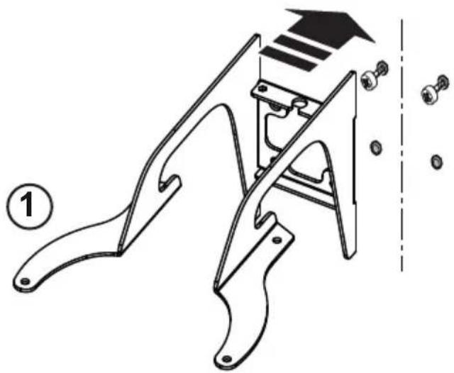
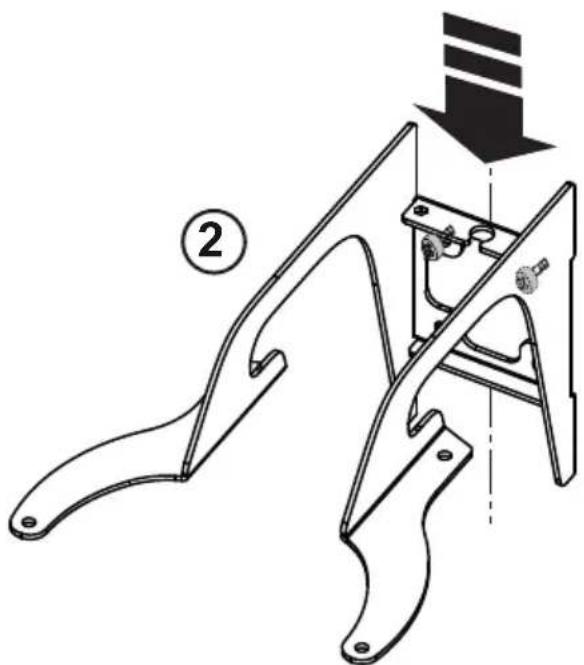
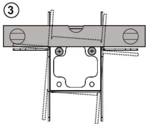
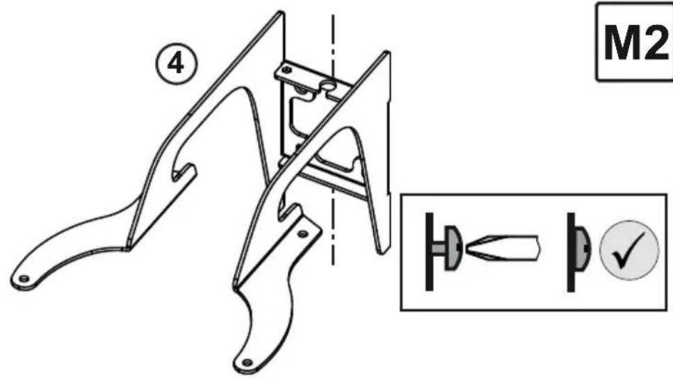
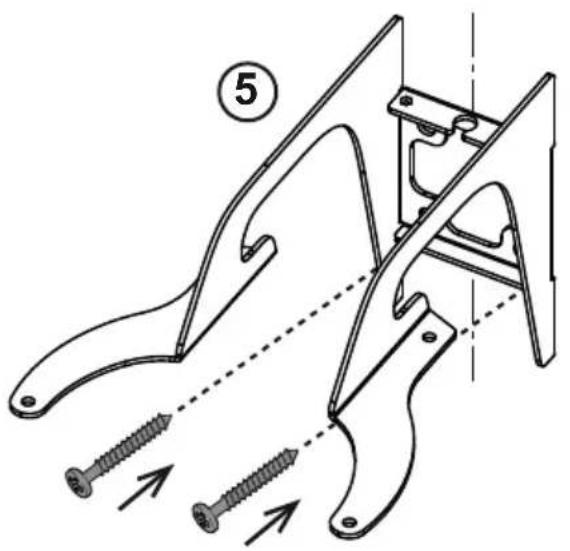
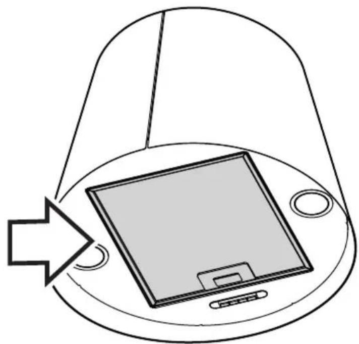
Mounting M1:
This type of cooker hood must be fixed to the ceiling.
Very heavy product; hood handling and installation must be carried out by at least two persons.
Operation
The hood is fitted with a control panel with aspiration speed selection control and a light switch to control cooking area lights.
A. on/off light switch
B. on/off aspiration switch and minimum power selection
B+C. medium power selection aspiration switch
B+D. maximum power selection aspiration switch
Note: if the hood is active at medium speed or at maximum speed, it is possible to turn off the suction using button B (on / off) without also deselecting button C or button D, in this condition when the hood is reactivated again, button B (on / off), suction will restart at the speed set in the previous use.
Maintenance
Cleaning
Clean using ONLY a cloth dampened with neutral liquid detergent. DO NOT CLEAN WITH TOOLS OR INSTRUMENTS. Do not use abrasive products. DO NOT USE ALCOHOL!
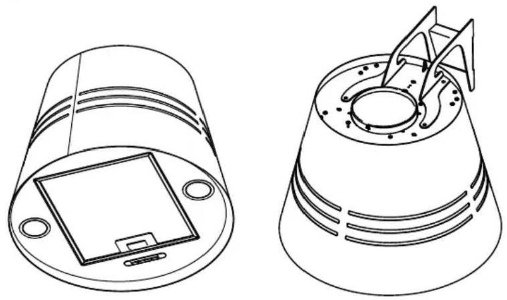
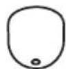
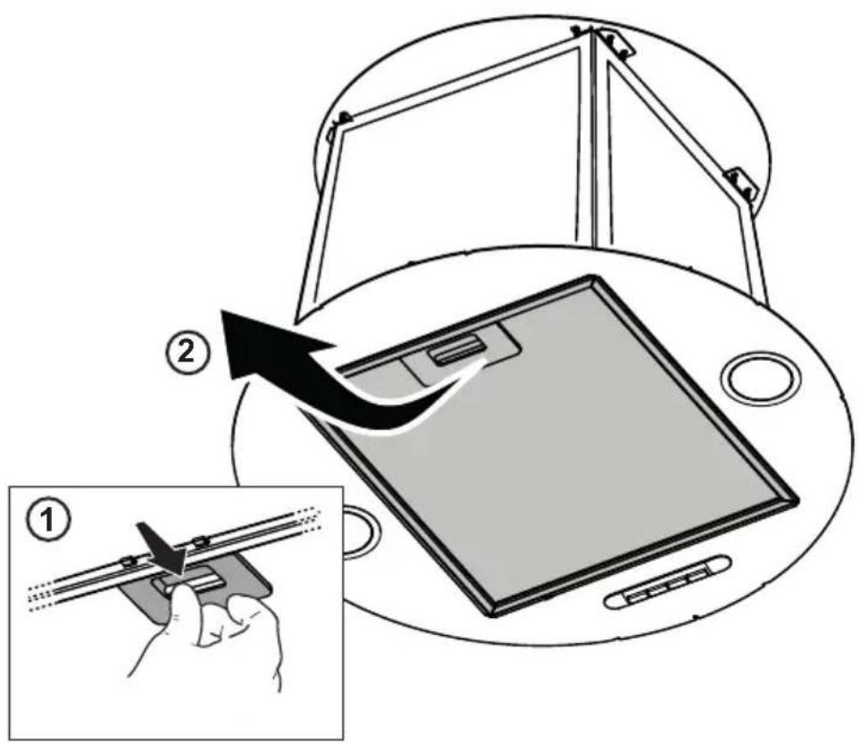
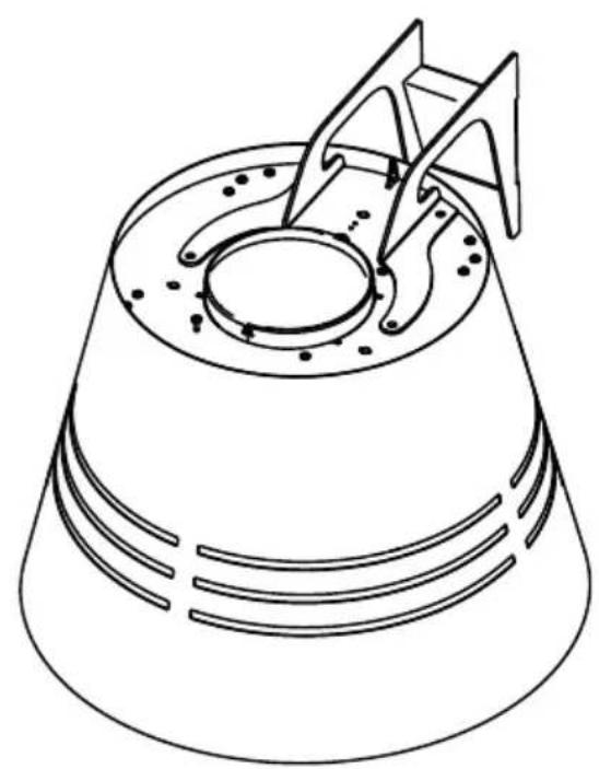
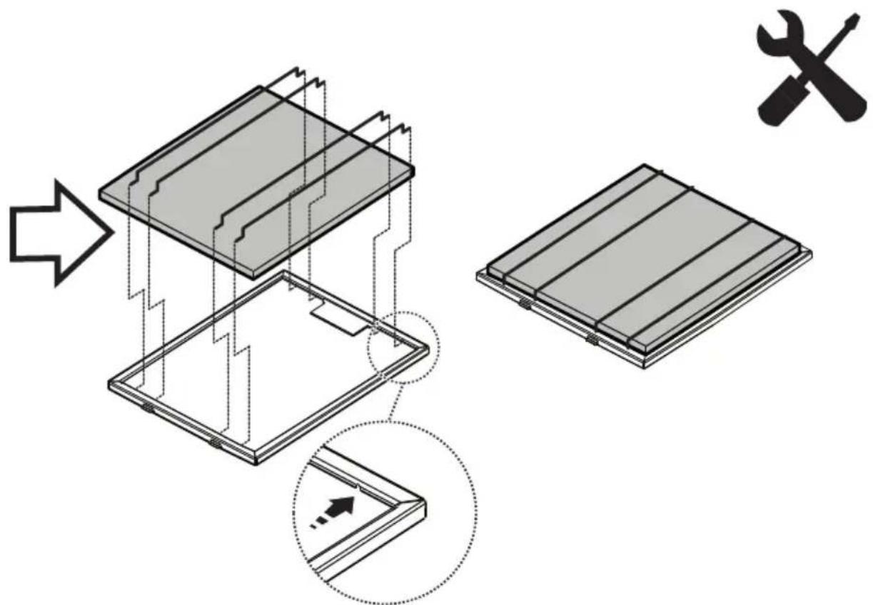
Grease filter
Fig. 35
Traps cooking grease particles.
The grease filter must be cleaned once a month using non aggressive detergents, either by hand or in the dishwasher, which must be set to a low temperature and a short cycle. When washed in a dishwasher, the grease filter may discolor slightly, but this does not affect its filtering capacity. To remove the grease filter, pull the spring release handle.
Charcoal filter
Fig. 34
It absorbs unpleasant odors caused by cooking.
The charcoal filter can be washed once every two months using hot water and a suitable detergent, or in a dishwasher at 65^ C (if the dishwasher is used, select the full cycle function and leave dishes out).
Eliminate excess water without damaging the filter, then put it in the oven for 10 minutes at 100^ C to dry completely. Replace the mattress every 3 years and when the cloth is damaged.
- Montage
Install the carbon filter on the back of the grease filter and fix with 4 rods.
Attention! The rods are included in the carbon filter packing and not on the hood.
- To dismantle the filter act in the reverse manner.
CLEANING AND UPKEEP OF YOUR APPLIANCE
To keep your appliance in good working order, we recommend that you use Clearit household products.

Professional expertise for the general public
Clearit offers you professional products and adapted solutions for the daily upkeep of your household and kitchen appliances.
You may find them in conventional retail outlets, along with a complete line of by-products and consumables.
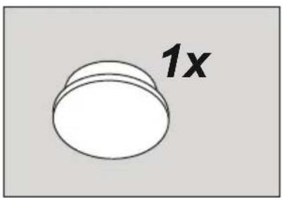
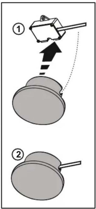
Replacing lamps
The hood is equipped with a lighting system based on LED technology.
The LEDs guarantee an optimum lighting, a duration up to 10 times longer than the traditional lamps and allow to save 90%
electrical energy.
The lighting system cannot be replaced by the user, contact Customer Service in case of malfunction.
- This appliance is marked according to the European directive 2012/19/EC - UK SI 2013 No.3113 on Waste Electrical and Electronic Equipment (WEEE). - By ensuring this product is disposed of correctly, you will help prevent potential negative consequences for the environment and human health, which could otherwise be caused by inappropriate waste handling of this product.
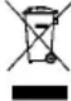
- The symbol ■ on the product, or on the documents accompanying the product, indicates that this appliance may not be treated as household waste. Instead it should be taken to the appropriate collection point for the recycling of electrical and electronic equipment. Disposal must be carried out in accordance with local environmental regulations for waste disposal. - For further detailed information regarding the process, collection and recycling of this product, please contact the appropriate department of your local authorities or the local department for household waste or the shop where you purchased this product.
Appliance designed, tested and manufactured according to:
- Safety: EN/IEC 60335-1; EN/IEC 60335-2-31, EN/IEC 62233.
• Performance: EN/IEC 61591; ISO 5167-1; ISO 5167-3; ISO 5168; EN/IEC 60704-1; EN/IEC 60704-2-13; EN/IEC 60704-3; ISO 3741; EN 50564; IEC 62301.
- EMC: EN 55014-1; CISPR 14-1; EN 55014-2; CISPR 14-2; EN/IEC 61000-3-2; EN/IEC 61000-3-3.
Suggestions for a correct use in order to reduce the environmental impact: Switch ON the hood at minimum speed when you start cooking and kept it running for few minutes after cooking is finished. Increase the speed only in case of large amount of smoke and vapor and use boost speed(s) only in extreme situations. Replace the charcoal filter(s) when necessary to maintain a good odor reduction efficiency. Clean the grease filter(s) when necessary to maintain a good grease filter efficiency. Use the maximum diameter of the ducting system indicated in this manual to optimize efficiency and minimize noise.
Troubleshooting
| SYMPTOMS | SOLUTIONS |
| The hood is not working... | Ensure that :• The power is not cut off.• A speed has been selected. |
| The hood is not operating effectively... | Ensure that :• The selected motor speed is sufficient for the quantity of smoke and vapours to be cleared.• The kitchen is sufficiently ventilated to allow for fresh air intake.• The air pipe circuit involves a lack of efficiency of the cooker hoods. Contact a qualified technician.• The carbon filter is not worn (hood operating in recycling mode). |
| The hood stopped working | Ensure that :• The power is not cut off.• The single-pole cut-off device was not activated. |
After-sales service
Any maintenance on your equipment should be undertaken by:
- either your dealer,
- or another qualified mechanic who is an authorized agent for the brand appliances.
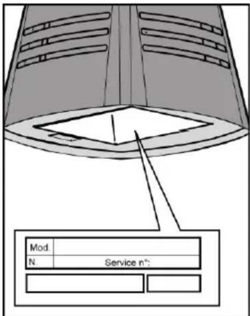
When making an appointment, state the full reference of your equipment (model, type and serialnumber).
This information appears on the manufacturer's nameplate attached to your equipment.
Brandt
Cara Cliente, Caro Cliente,
natural_image
Technical line drawing of a device casing with internal components and three vertical posts (no text or symbols)M2
natural_image
Technical line drawings of two electronic components with internal circuitry (no text or symbols)

natural_image
Two identical black silhouette figures of men, no text or symbols present
natural_image
Illustration of two gloves, one open and one closed, with no text or symbols present.
natural_image
Simple line drawing of an open cardboard box (no text or symbols)1x1x
natural_image
Illustration of stacked sheets with a central crosshair and number 1 (no text or symbols)3x
natural_image
Abstract spiral line drawing with no text or symbols

3x

3x
5x
ø5X35mm
5x
∅8x40mm

3x

3x
6x
ø2,9x9,5mm


1x
∅3,5x9,5mm
1x
3x
natural_image
Simple line drawing of a trapezoidal shape with arrows indicating direction and a small asterisk symbol, next to a vertical stack of squares (no text or labels)

natural_image
Technical line drawing of a mechanical component with mounting holes and a central display (no text or symbols)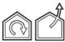
M1
1.1
M1
2
M1
3x Ø8x40mm
3
4
6
7
8
natural_image
Technical illustration of a mechanical component with mounting base and internal structure (no text or symbols)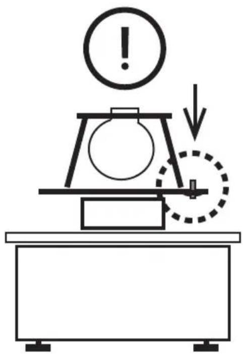
natural_image
Simple line drawing of a mechanical setup with an exclamation mark and downward arrow, no text or symbols present.
natural_image
Diagram of a mechanical device with rotating components and directional arrows, no text or symbols present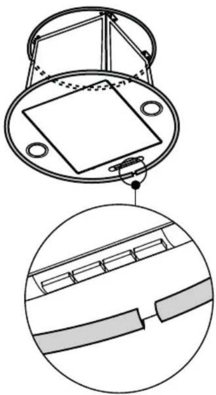
natural_image
Technical diagram of a mechanical component with cross-sectional view and detail view (no text or symbols)10
natural_image
Technical line drawing of a mechanical component with mounting base and circular features (no text or symbols)
M1
natural_image
Technical illustration of a conical device with internal components and a close-up view showing internal structure (no text or symbols)12
natural_image
Technical diagram of a mechanical assembly with arrows indicating motion or force directions (no text or symbols present)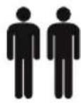


M1

V-Hz
natural_image
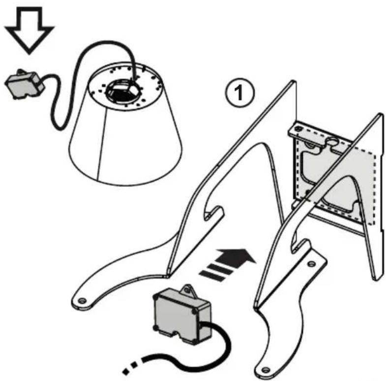
Diagram of a device connected to a conical lamp with a cable, showing internal components and wiring (no text or symbols)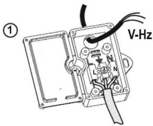
natural_image
Diagram of a mechanical component with screws and a clip, no text or symbols present
natural_image
Line drawing of a conical lamp with a central cable and three vertical posts (no text or symbols)
natural_image
Technical line drawing of a conical mechanical component with internal cavities and mounting holes (no text or symbols)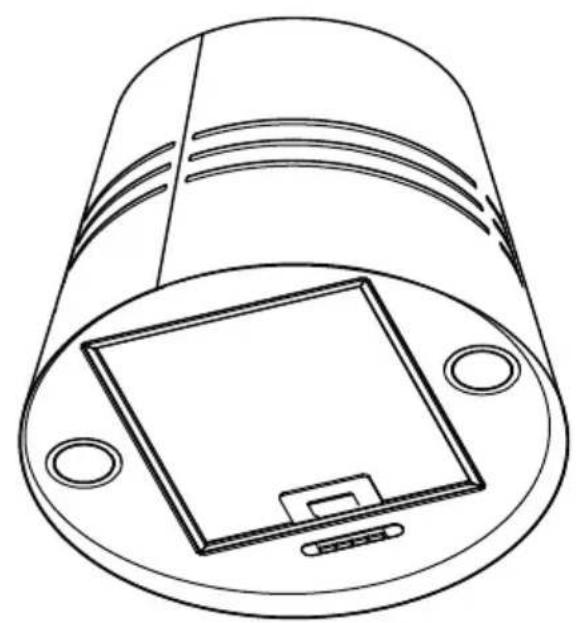
natural_image
Technical line drawing of a cylindrical electronic component with a square base and mounting holes (no text or symbols)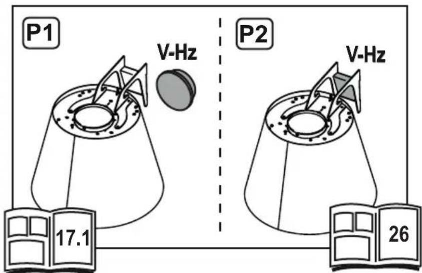
M2
P1
18
4x ∅ 8mm
M2
P1

19
M2
P1
natural_image
Technical line drawing of a mechanical component with no visible text or symbolsM2

20.1
20.2
21
4x
M6 x 16 mm

M2
22
23
2x ∅ 8mm
24
flowchart
graph LR
    A["Document Image"] --> B["15"]
    B --> C["25..."]

natural_image
Technical line drawing of a mechanical device with a conical base and attached component (no text or symbols)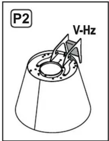
M2
P2


natural_image
Technical line drawing of a mechanical device with no visible text or symbols

natural_image
Diagram of a mechanical device inside a frame with directional arrow indicating motion (no text or symbols)
natural_image
Pure mechanical assembly diagram without any text, numbers, or symbols28
29
M2
P2
M2
P2
30
31
natural_image
Mechanical assembly diagram showing a lever mechanism with a curved tool and mounting bracket (no text or symbols)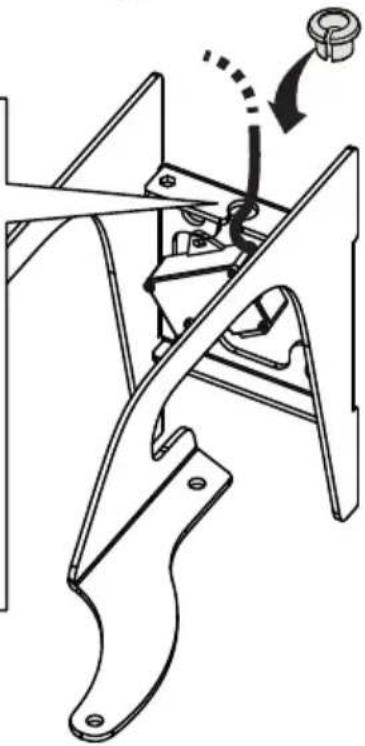
natural_image
Mechanical assembly diagram showing a bracket with mounting holes and a hanging nut (no text or symbols)32

32.1
flowchart
graph LR
    A["32.2"] --> B["22"]
    B --> C["33..."]
natural_image
Diagram of a device component with an arrow pointing to a square panel, no text or symbols present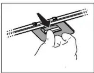
natural_image
Illustration of a hand using a tool to adjust or install a mechanical component (no text or symbols visible)33
34

natural_image
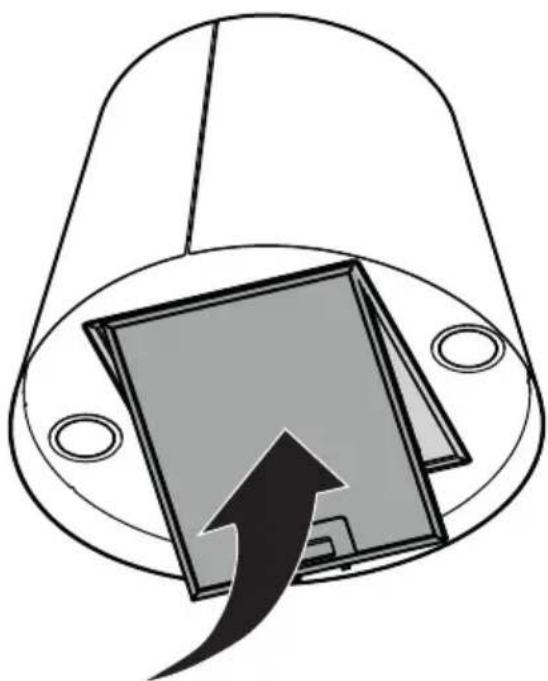
Diagram of a device inside a dome-shaped enclosure with an arrow pointing to its front panel (no text or symbols)
35

- RELATIONS CONSOMMATEURS France
- Contents
- Electrical risks
- Risk of asphyxiation
- Risk of fire
- Instruction on mounting and use
- Use
- Installation
- Electrical connection
- Mounting
- Before beginning installation:
- Operation
- Maintenance
- Cleaning
- Grease filter
- Fig. 35
- Charcoal filter
- Fig. 34
- - Montage
- CLEANING AND UPKEEP OF YOUR APPLIANCE
- Professional expertise for the general public
- Replacing lamps
- After-sales service
- Brandt
Brand : BRANDT
Model : BHI1043X
Category : Basket