AR10410T - Remote control toy SPEKTRUM - Free user manual and instructions
Find the device manual for free AR10410T SPEKTRUM in PDF.
User questions about AR10410T SPEKTRUM
0 question about this device. Answer the ones you know or ask your own.
Ask a new question about this device
Download the instructions for your Remote control toy in PDF format for free! Find your manual AR10410T - SPEKTRUM and take your electronic device back in hand. On this page are published all the documents necessary for the use of your device. AR10410T by SPEKTRUM.
USER MANUAL AR10410T SPEKTRUM
SPMAR1041OT, SPMAR1441OT, SPMAR2041OT
Updated 9/24 41201.3
NOTICE
All instructions, warranties and other collateral documents are subject to change at the sole discretion of Horizon Hobby, LLC. For up-to-date product literature, visit horizonhobby.com or towerhobbies.com and click on the support or resources tab for this product.
Meaning of Special Language
The following terms are used throughout the product literature to indicate various levels of potential harm when operating this product:
WARNING: Procedures, which if not properly followed, create the probability of property damage, collateral damage, and serious injury OR create a high probability of superficial injury.
CAUTION: Procedures, which if not properly followed, create the probability of physical property damage AND a possibility of serious injury.
NOTICE: Procedures, which if not properly followed, create a possibility of physical property damage AND a little or no possibility of injury.

WARNING: Read the ENTIRE instruction manual to become familiar with the features of the product before operating. Failure to operate the product correctly can result in damage to the product, personal property and cause serious injury.
This is a sophisticated hobby product. It must be operated with caution and common sense and requires some basic mechanical ability. Failure to operate this Product in a safe and responsible manner could result in injury or damage to the product or other property. This product is not intended for use by children without direct adult supervision. Do not attempt disassembly, use with incompatible components or alter product in any way without the approval of Horizon Hobby, LLC. This manual contains instructions for safety, operation and maintenance. It is essential to read and follow all the instructions and warnings in the manual, prior to assembly, setup or use, in order to operate correctly and avoid damage or serious injury.
Age Recommendation: Not for children under 14 years. This is not a toy.
WARNING AGAINST COUNTERFEIT PRODUCTS
Always purchase from a Horizon Hobby, LLC authorized dealer to ensure authentic high-quality Spektrum product. Horizon Hobby, LLC disclaims all support and warranty with regards, but not limited to, compatibility and performance of counterfeit products or products claiming compatibility with DSM or Spektrum technology.
NOTICE: This product is only intended for use with unmanned, hobby-grade, remote-controlled vehicles and aircraft. Horizon Hobby disclaims all liability outside of the intended purpose and will not provide warranty service related thereto.
WARRANTY REGISTRATION
Visit www.spektrumrc.com/registration today to register your product.
AR10410T, AR14410T, AR20410T PowerSafe Receivers
The Spektrum™ AR10410T, AR14410T and AR20410T Receivers are full range with telemetry, and are compatible with all Spektrum™ DSM2® and DSMX® technology transmitters.
Perform the setup for these receivers through a compatible Spektrum Transmitter with Forward Programming. The Spektrum PC Programmer can be used for firmware updates.
| Specifications | |
| Type PowerSafe DSMX | Telemetry Receiver |
| Application Airplane | |
| Channels 20 | |
| AS3X+ Available with optional Synapse sensor | |
| Remote Receivers | (2-4) SRXL2™ Remote Receivers [3-SPM9747 and 1-SPM4651T Included] |
| Modulation DSMX | |
| Telemetry Integrated | |
| Bind Method Bind Button, Bind Plug | |
| Failsafe Yes | |
| Power Button On Receiver, Remote Switch | |
| Band 2.4GHz | |
| Input Connector (2) IC3 | Input Connectors with Smart Technology |
| Input Voltage | 4V-12.6V |
| Resolution | 2048 (4096 for Stabilization) |
| AR10410T 10CH | 2.56” x 2.44” x 0.71” (65mm x 62mm x 18mm) |
| 1.77 oz (50g) | |
| AR14410T 14CH | 2.56” x 2.44” x 0.71” (65mm x 62mm x 18mm) |
| 2.68 oz (76g) | |
| AR20410T 20CH | 2.4” x 2.72” x 0.75” (61mm x 69mm x 19mm) |
| 2.82 oz (80g) | |
IMPORTANT: These receivers only use forward programming for the configuration, do not use the AS3X menu in the main transmitter menu.

WARNING: For electric powered aircraft and if equipped, the
propeller should not be installed on the motor during the setup
procedure. Only install the propeller once the throttle has been confirmed to operate correctly and the failsafe has been set.
As an additional safety feature, we recommend the throttle cut is enabled. Throttle cut should be engaged any time the aircraft is powered on and not in operation. The motor will not rotate when throttle cut is in the ON position.
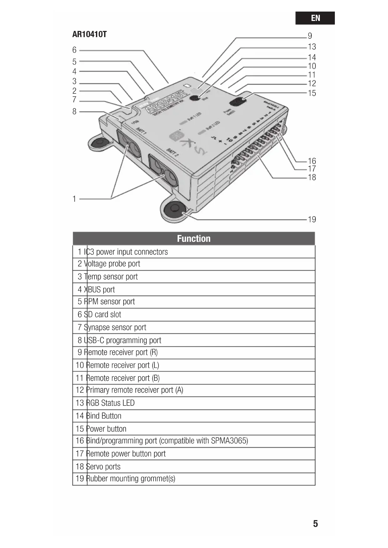
Receiver Diagrams
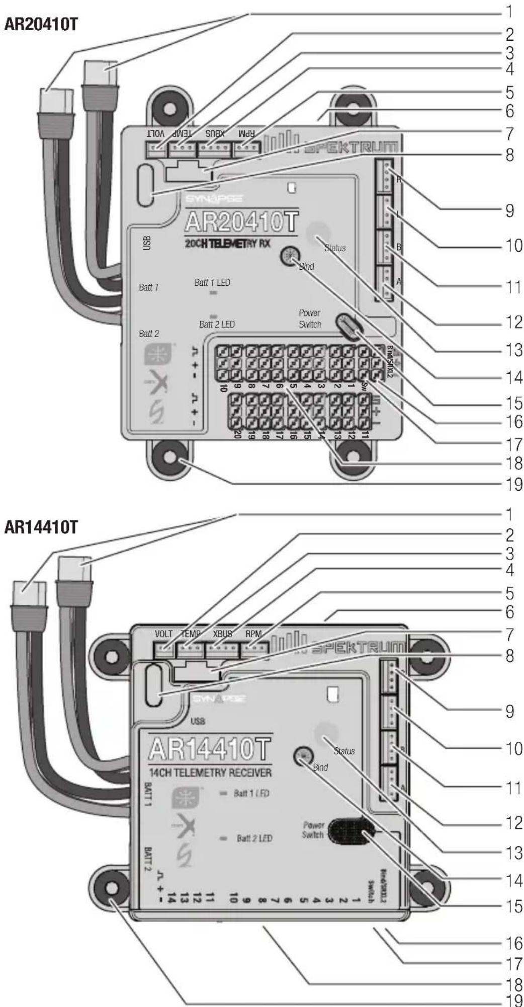
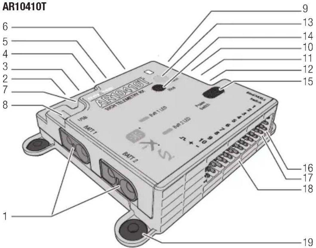
| Function |
| 1 IC3 power input connectors |
| 2 Voltage probe port |
| 3 Temp sensor port |
| 4 XBUS port |
| 5 RPM sensor port |
| 6 SD card slot |
| 7 Synapse sensor port |
| 8 USB-C programming port |
| 9 Remote receiver port (R) |
| 10 Remote receiver port (L) |
| 11 Remote receiver port (B) |
| 12 Primary remote receiver port (A) |
| 13 RGB Status LED |
| 14 Bind Button |
| 15 Power button |
| 16 Bind/programming port (compatible with SPMA3065) |
| 17 Remote power button port |
| 18 Servo ports |
| 19 Rubber mounting grommet(s) |
Scan the QR for more information on advanced setup.
Installing the Receiver
-
Mount the receiver using the four rubber mounting grommets on the side of the case, screwed into a solid mounting platform. The receiver may be mounted in any mounting orientation.
-
If using the optional Synapse sensor, mount the sensor square/parallel with the centerline of the airplane. It only needs to be parallel to the centerline, it does not need to be on the centerline of the airplane.
- If using the optional Synapse sensor, Connect the cable between the sensor and receiver.
IMPORTANT: For SAFE setups, install the Synapse sensor as close to the center of gravity of the aircraft as practical.
- Connect the servos to their respective ports on the receiver.
CAUTION: when using the Synapse and AS3X+, incorrect installation of the sensor could cause a crash. Always perform a control surface check and AS3X+ control surface response test before flying a new setup, or after any setup changes. We recommend using the gyro response test setting to make gyro direction more visible, see AS3X+ Reaction Test in this manual for more information.
Default Channel Assignments
Default channel assignments will change with transmitter selections for wing, tail, flaps and more. Follow the channel assignments defined in your transmitter after going through configuration for your model.
For electric models using a Spektrum Avian ESC, the throttle port should always be the #1 servo port, for Smart telemetry to function. Throttle will function in other channels, but there will not be telemetry. To use a Avian ESC in Smart mode and change needs to be made after binding. Enter Forward Programming, select Other Settings, select Frame Rate, and change the Output Channel 1 to SRXL2. For more information about using an ESC, see Powering the Receiver from the Servo Rail later in this manual.
You may use up to 14 channels in 14 ch mode for primary flight controls. Or, use up to 12 channels for flight controls, and channels 13-20 as secondary functions, called XPLUS channels. Enable XPLUS mode in your transmitter under the frame rate menu to enable these channels. XPLUS channels should be used for axillary controls, not primary flight controls.
IMPORTANT: When using Y-harness or servo extensions with Spektrum equipment, do not use reversing harnesses. Using reversing Y-harnesses or servo extensions may cause servos to operate erratically or not function at all.

Remote receivers may be mounted with foam insulated double sided tape, adhesive backed hook and loop tape, or silicone glue.
One 4651T telemetry remote receiver is included, and is required for full range telemetry operation. It may be connected to any remote receiver port (A, B, L, R). At least two remote receivers are required for operation, and there must be a remote receiver connected in port A.
Antenna Placement
Spektrum Multilink technology gives you the protection of multiple remote receivers working together to deliver a robust control link, but your installation plays a critical role in the performance of the control link.
Remote receivers should be placed as far away from conductive materials on the aircraft as possible such as motors, batteries, fuel tanks, engines, mufflers, wiring and anything made of metal. Special consideration is needed for composite models with carbon fiber construction. Receiver antennas should never be placed in locations where they are enclosed or blocked by carbon fiber.
Any electronic component should be considered a possible source of RFI (Radio Frequency Interference) including BECs, electronic speed controllers, electronic ignition systems, and cameras. Locate the remote receivers as far from any sources of RFI as possible.
Antennas should be placed in different orientations and locations to maximize the effectiveness of multilink technology. There should always be one or more receiver antennas with an optimal path to the transmitter, regardless of the model's orientation. Antennas should be oriented with one antenna vertical, and one antenna horizontal. If you have a system with three antennas we suggest installing two antennas vertical, one horizontal. If you have a system with four antennas we suggest installing two antennas vertical, one horizontal parallel to the direction of flight and one horizontal perpendicular to the direction of flight. Always try to maximize separation between the remote receivers to further improve control link performance.
The three included SPM9747 remote receivers have an antenna integrated into the circuit board, there is no external antenna.
The included SPM4651T telemetry remote receiver has coaxial style antennas. The last 31mm at the end of the coaxial cable is the active antenna element and what needs the most consideration for placement on this remote receiver.
NOTICE: Do not cut, kink, or modify the antennas. Damage to the coaxial portion of an antenna will reduce the performance of the antenna. Shortening or cutting off the 31mm tip will reduce the range.
Powering the Receiver
Dual PowerSafe Input Leads
The AR10410T, AR14410T and AR20410T receivers are designed to be powered by two matching batteries, up to 3S Li-Po through the two IC3 input leads. The receiver does not regulate the voltage from the batteries, it will switch between power sources to maintain the highest voltage possible at all times.
These receivers are designed to be powered from the IC3 power input leads by default, which is the recommended configuration to be able to take advantage of the built-in safety features. PowerSafe safety features include the power button and fast boot functionality. Do not connect a battery or an ESC with a BEC to the servo rails when using the PowerSafe system.
Powering on the Receiver With PowerSAFE
By default, the receiver may be powered on from the built-in button on the receiver case, or with an external power button connected to the switch port (Sw). Only use the included momentary button for remote switch functionality.
Power button (or remote switch) functionality:
- Connect your fully charged (matched) batteries to the IC3 battery connectors.
- Hold the button for the system to power on.
- Tap, release, then press and hold to power off.
- You may leave the batteries connected during a flying session.
- For transportation and storage we recommend disconnecting your receiver batteries after powering the system off.
IMPORTANT: Do not disconnect the batteries from the receiver to power it off when using the PowerSafe system. If you pull power from the receiver without powering if off first, it will bypass the power button and normal initialization steps because it is meant as a brownout recovery feature.
Sleep and Wake From Your Transmitter
Use the quick double tap feature on your transmitter to bring up the sleep screen. Once updated to the newest firmware, your transmitter will show options for the receiver as well. You cannot power the receiver on from the transmitter. Once powered on and connected, you have the option to power the receiver off or put it to sleep from the airware menu on your Spektrum transmitter. If the pair are put to sleep together, the transmitter will ask if you want to wake up the receiver when you wake up the transmitter. The receiver will display a slow blue flashing LED when in sleep mode.
Powering the receiver from the Servo Rail
If you wish to use an ESC with a BEC (provides voltage to the servo rail from the flight battery), you must first power the receiver with a battery connected to an IC3 battery input lead. Power the receiver on with the button, bind and enter the forward programming menu > PowerSafe Telemetry > Power Source and change the selection from Battery Ports to Servo Rail. Exit Forward
Programming and reboot the receiver to save the changes. If you are using this setting the power button will not function, and you cannot sleep the receiver from your transmitter. With this setting you can power the receiver on like any conventional receiver by connecting power to the servo rail.
Transmitter and Receiver Binding
The receiver must be bound to your transmitter before it will operate. Binding is the process of teaching the receiver the specific code of the transmitter so it will only connect to that specific transmitter.
- Connect the SRXL2 remote receivers (SPM4651T, SPM9747) and any telemetry sensors to the main receiver.
- Connect your batteries to the IC3 input connectors
- Push and hold the power button on the receiver to power it on.
- Press and release the bind button until the orange LEDs on the receiver and the remote receivers start to flash, indicating the receiver is in bind mode.
- Put your transmitter in bind mode.
- The bind process is complete when the orange LEDs remain solid. Once a bind is established, the bind data will be relayed throughout the system.
IMPORTANT: It is still possible to use a bind plug in the bind port if desired. This can come in handy if the receiver needs to be mounted in a location that is difficult to access, in which case a servo extension may be used for binding. If using a bind plug, remove after binding to prevent the system from entering bind mode the next time the power is turned on.
IMPORTANT: You may also put the system into bind mode by pressing a bind button on one of the remote receivers (the system won't enter bind if it has been connected to a transmitter since being powered on).
IMPORTANT: Bind data is verified on every startup. Thanks to this feature, it is not necessary to re-bind the system if a remote receiver is replaced.
Telemetry
The AR10410T, AR14410T and AR20410T receivers feature full range telemetry and will provide receiver battery voltage, flight log data, and variometer and altitude data without any additional sensors. Additional telemetry devices such as voltage sensors can be connected to the volt port, and XBus telemetry sensors can be connected through the XBus connector. Many XBus telemetry devices have two XBus ports, and XBus telemetry sensors can be connected in a daisy chain in any order. The Spektrum Sky Remote ID module (SPMA9500) may be connected to the bind port, remote rx port (B,L,R), or #1 servo port.*
All telemetry connections with the system take place through the 4651T. If telemetry connection problems exist, investigate the placement of the 4651T antennas. It is also possible to use more than one 4651T telemetry remote receiver to improve the received telemetry performance on the ground.
See www.spektrumrc.com for more information about telemetry accessories.
- A Y-harness may be used with a Spektrum Avian Smart ESC on the #1 servo port. Do not use a Y-harness for a conventional servo or ESC.
Initial Setup
- Verify your transmitter is updated to the latest Spektrum AirWare™ software. See your transmitter manual for updating instructions.
- Install the receiver in your airplane.
- Bind the receiver to your transmitter.
- Complete the airplane setup on your transmitter including wing type, tail type, channel assignments, mixing, sub trim and travel the same as you would for any other aircraft without AS3X+. Verify the center of gravity is correct and test fly your aircraft.
IMPORTANT: Do not use open mixes for primary flight control setup on the AR10410T, AR14410T, and AR20410T receivers when using a Synapse for AS3X+ and SAFE. If necessary, refer to aux output setup online to add stabilization to secondary functions.
Failsafe
In the unlikely event the radio link is lost during use, the receiver will enable the selected failsafe mode. Smart Safe + Hold Last is the default failsafe mode on the receiver. Preset Failsafe and SAFE Failsafe modes are only available through Forward Programming.
SmartSafe + Hold Last
If loss of signal occurs, SmartSafe™ technology moves the throttle channel to the failsafe position (low throttle) set during binding. All other channels will hold their last position. When the receiver detects the signal from the transmitter, normal aircraft operation resumes.
Preset Failsafe
With preset failsafe, you can set the specific control surface positions you want to use if the signal is lost. When the receiver detects the signal from the transmitter, normal aircraft operation resumes.
Preset failsafe mode is only available through Forward Programming.
SAFE Failsafe
(Available with Synapse sensor) SAFE Failsafe mode will work to automatically level your aircraft if the signal is lost. In the forward programming menu you can select the bank and pitch angles the aircraft will attempt to maintain during failsafe. We recommend setting bank and pitch angles so the aircraft flies a gentle gliding turn, preventing a flyaway. You must complete First Time SAFE
Setup before this option is available.
SAFE Failsafe mode is only available through Forward Programming.
Testing Failsafe
Secure the aircraft on the ground and remove the propeller, if equipped. Test Failsafe settings by turning the transmitter RF output off and noting how the receiver drives the control surfaces.
Receiver Power Only
- The servo ports will not have a control signal if the receiver is turned on when no transmitter signal is present.
- All channels have no output until the receiver has linked to the transmitter.
Before each flying session, and especially with a new model, it's important to perform a range check. All Spektrum aircraft transmitters incorporate a range testing system, which reduces the output power to allow a range check.
- With the model resting on the ground, stand approximately 100 feet (30 meters) away from the model.
- Face the model with the transmitter in your normal flying position and put your transmitter into range test mode.
- You should have total control of the model in range test mode at 100 feet.
- If you have control issues, review the flight log data to help reposition your antenna(s), and repeat the range test.
- If control issues persist, call Horizon Product Support for further assistance.
Advanced Range Testing
The standard range testing procedure is recommended for most sport aircraft. For sophisticated aircraft that contain significant amounts of conductive materials (e.g. turbine powered jets, scale aircraft with metalized finishes, aircraft with carbon fuselages, etc.), the following advanced range check will confirm that all receivers in the system are operating optimally as installed. This advanced range check allows the RF performance of each receiver to be evaluated independently. A telemetry-equipped Spektrum Transmitter is required for the advanced range test.
- Stand approximately 100 feet away from the model.
- Face the model with the transmitter in your normal flying position and put your transmitter into range test mode.
- Have a helper position the model in various orientations (nose up, nose down, nose toward the transmitter, nose away from the transmitter, etc.).
- Observe the telemetry on your transmitter. Note any orientations that cause higher fades or frame loss values. Perform this step for at least one minute.
- Reposition any remote receivers showing higher fades as necessary.
- Retest to verify satisfactory results.
- Repeat as necessary.
After one minute, advanced testing should yield:
H-0 holds
F - Fewer than 10 frame losses
A, B, L, R - Fades will typically be fewer than 100. It's important to compare the relative fades. If a particular receiver has a significantly higher number of fades (2 to 3X) then the test should be redone. If the same results occur, move the offending receiver to a different location.
TIP: Use the fade values for the 4651T telemetry remote receiver to investigate the performance of the telemetry link.
Flight Log data can help you optimize the control link for your aircraft. Flight Log data is displayed on telemetry capable Spektrum transmitters.
Using the Flight Log
A - Fades on primary remote receiver
B - Fades on remote receiver
L - Fades on remote receiver
R - Fades on remote receiver
F - Frame losses H - Holds
Fades
Represents the loss of one bit of information on one receiver. Fades are used to evaluate the performance of each individual remote receiver. If a fade value is showing higher than the others, inspect or reposition the remote receiver or it's antenna(s) to optimize the RF link.
Remote receiver fades in flight log telemetry report as "—" when they have no RF data. This can help identify remote receivers that aren't bound, damage to the remote receiver wires, or connectors that are not fully seated.
Frame Loss
A frame loss occurs when one complete data packet is missed. A single frame loss does not represent a loss of control, but frame losses should be monitored. In the air it's normal to experience as many as 100 frame losses per minute of flight. On the ground the number of frame losses will be higher because the signal is hampered by the dirt and moisture.
Hold
A hold occurs when 45 consecutive frame losses occur. This takes about one second, and in this event the receiver moves the channel outputs to the failsafe settings. If a hold ever occurs, it's important to re-evaluate the system and check every component. If your system displays a hold, diagnose the cause and resolve the issue before flying again.
IMPORTANT: It is normal to see a hold logged if you power OFF your transmitter and back ON.
IMPORTANT: The Spektrum Flight Log (SPM9540) is not compatible with the AR10410T, AR14410T or AR20410T receivers.
- Make sure your airplane is set up for flying (reversing, travel, subtrims, etc). Run through the First Time setup in forward programming and assign a channel for adjusting the gain such as the rotary knob or slider.
- Before flying, gyro response direction can be verified using the Gyro Response Test menu (Gyro Settings > System Setup > Utilities > Gyro Response Test).
- Use the gain channel to adjust gain in flight and evaluate the gyro response. Gain should be tuned while flying near or at max speed.
a. In most cases, the pilot will be able to find a gain value that offers improved performance without additional tuning of individual settings.
b. Due to the addition of the new parameter Stop Lock Rate delaying gain return from centering the stick, the gain might end up too high without the pilot noticing. This is more likely to happen on a calm day because turbulence from wind will induce oscillations which will highlight when the gain is too high.
i. The preferred method of addressing this is to temporarily increase Stop Lock Rate to 100% for all 3 axes. Then stick inputs can be used to evaluate the current gain. This will ensure having full or closer to full gain the moment the stick is released. Start with low gain and work up. If the model continuously oscillates/bounces more than once, then the AS3X + gain is too high and needs to be reduced (One or two bounces are acceptable). Once the gain is set, the Stop Lock Rate can be reset back to defaults to remove any small oscillations.
ii. Another method of testing the gain which is quicker but less effective, is to leave the Stop Lock Rate at defaults. Then, use short/quick stick inputs, returning quickly to center, to induce movement in the model. Due to these delays, short/quick inputs will reduce gain much less, and will allow the model to stop more with the gyro as opposed to naturally.
- If any movement other than Roll starts experiencing oscillations as gain is increased, Pitch and Yaw can be reduced in Gyro Settings>AS3X+ Settings>AS3X+ Gain.
- If the gain channel is all the way up and no oscillations can be induced in the model, the multiplier can be increased in Gyro Settings>AS3X+ Settings. Conversely, if the gain channel is barely increased and oscillations are observed, the gain multiplier should be decreased to provide a wider window of adjustment.
- Once the preferred flight performance is achieved, use the Capture gain settings feature (Gyro Settings > AS3X+ Settings > Capture Gyro Gains) This page will preview where your gain will be at once captured. Use this to lock the gains in this position. Once the Capture Gyro Gains selection has been used any adjustable gains selections in that flight mode will be defaulted back to fixed. The selected gyro gain switch is changed to inactive, and the model can be flown as normal. Or, you can move on to the Advanced Tuning for more refined options
Gyro Response Direction Test (when using a Synapse)
This test ensures that the AS3X+ control system has the directions and any auxiliary control surface configurations set up properly.
- Assemble the aircraft, bind your transmitter to the receiver, and complete the AS3X+ First Time Setup in the Forward Programming menu before performing this test.
- From the Forward Programming menu select Gyro Settings > System Setup > Utilities > Gyro Response Test. This test will set all gyro response to maximum gain to make it easy to see control direction response. Do not fly in the Gyro Response Test mode.
- Move the aircraft as shown and ensure the control surfaces move in the direction indicated in the graphic. If the control surfaces do not respond as shown, do not fly the aircraft.
| Aircraft Movement Control Surface Reaction | ||
| RudderElevator | ||
The Gyro Response Test is only a direction test, it does not test if you have gain applied in a given flight mode/configuration.
- If the control surfaces do not respond as shown, review the receiver mounting orientation.
a. In your transmitter's menu select Forward Programming -> Gyro Settings -> System Setup -> Orientation
b. Verify the Synapse sensor orientation matches the selected diagram. The image of the airplane is from the top. If your access to the sensor is from the bottom, remember the images on the screen need to match the way the sensor sits in the model when it is upright.
AS3X+ Preflight Test (when using a Synapse)
This test ensures that the AS3X+ control system is functioning properly.
- Use the Gyro Response Test in the Forward Programming menu to verify the control surfaces are responding in the correct direction before performing this test.
- Raise the throttle above 25% to activate AS3X+, then lower the throttle. Once the AS3X+ system is active, control surfaces move in response to aircraft movement. AS3X+ remains active until the battery is disconnected.

CAUTION: Activate throttle cut to prevent motor operation during this test.
- Move the aircraft and ensure the control surfaces respond, and verify you understand how the gains are applied in each flight mode/configuration.
| LED Status Codes | |
| Green Normal operation | |
| Blue Normal operation, SD card logging | |
| Yellow, Blue, and Red Alternating | Receiver is in boot up or shut down |
| Pulsing Blue Sleep mode | |
| Green and Red Alternating | Receiver is in fast boot mode, which indicates an interruption to the power supply during use (brownout). |
| 1 Red Flash Too few remotes or no remote plugged into port “A” | |
| 2 Red Flashes | Waiting on power checks to fail. This can be held up by overvoltage without enabling 12v mode, detecting power on the servo rail when using battery port power mode, or detecting a battery connected when using servo rail power mode. |
| 4 Red Flashes | Synapse failure. Usually an indication that the connection to the Synapse sensor has failed after it was detected on startup and initialized. |
Optional Accessories
| Optional Accessories | |
| SPMA3065 USB Programming Cable | |
| SPM9747 SRXL2 DSMX Remote Receiver | |
| SPM4651T SRXL2 DSMX Remote Receiver | |
| Telemetry Sensors and Accessories | |
| SPMA9500 Sky Remote ID Module | |
| SPMA95871 Aircraft Telemetry GPS Sensor | |
| SPMA9551 12" Aircraft Telemetry Extension | |
| SPMA9552 24" Aircraft Telemetry Extension |
Troubleshooting Guide AS3X+ (when using a Synapse)
| Problem Possible Cause Solution | ||
| Oscillation | Damaged propeller or spinner | Replace propeller or spinner |
| Imbalanced propeller | Balance the propeller | |
| Motor vibration | Replace parts or correctly align propeller or other parts and tighten fasteners as needed | |
| Synapse sensor not mounted securely | Align and secure the sensor in fuselage | |
| Loose aircraft controls | Tighten or otherwise secure parts (servo, arm, linkage, horn and control surface) | |
| Worn parts | Replace worn parts (especially propeller, spinner, or servo) | |
| Irregular servo movement | Replace servo and/or servo extension(s) | |
| Gain too high Reduce gain | ||
| Inconsistent flight performance | Trim changes after initial setup | If you adjust trim more than 8 clicks, select Relearn Servo Settings in the Forward Programming menu after landing |
| Changes to Sub-Trim after initial setup | If you need to trim the aircraft during test flights, select Relearn Servo Settings in the Forward Programming menu after landing | |
| Aircraft was not kept immobile for 5 seconds after battery connection | With the throttle stick in lowest position. Disconnect battery, then reconnect battery and keep the aircraft still for 5 seconds. | |
| Incorrect response to the AS3X+ Control Direction Test | Incorrect direction settings in the receiver, which can cause a crash | DO NOT fly. Correct the direction settings, then fly. |
Troubleshooting Guide
| Problem Possible Cause Solution | ||
| Aircraft will not respond to throttle but responds to other controls | Throttle not at idle and/or throttle trim too high | Reset controls with throttle stick and throttle trim at lowest setting |
| Throttle servo travel is lower than 100% | Make sure throttle servo travel is 100% or greater | |
| Throttle channel is reversed | (With battery disconnected from aircraft) Reverse throttle channel on transmitter | |
| Motor disconnected from ESC | Make sure motor is connected to the ESC | |
| Aircraft will not Bind (during binding) to transmitter | Aircraft or transmitter is too close to large metal object, wireless source or another transmitter | Move aircraft and transmitter to another location and attempt binding again |
| The bind plug is not installed correctly in the bind port | Install bind plug in bind port and bind the aircraft to the transmitter | |
| Flight battery/transmitter battery charge is too low | Replace/recharge batteries | |
| Bind button not held long enough during bind process | Power off and repeat bind process. | |
| Aircraft will not connect (after binding) to transmitter | Aircraft or transmitter is too close to large metal object, wireless source or another transmitter | Move aircraft and transmitter to another location and attempt connecting again |
| Bind plug left installed in bind port | Rebind transmitter to the aircraft and remove the bind plug before cycling power | |
| Aircraft bound to different model memory. | Select correct model memory on transmitter | |
| Flight battery/Transmitter battery charge is too low | Replace/recharge batteries | |
| Transmitter may have been bound to a different aircraft using different DSM protocol | Rebind aircraft to transmitter | |
| Control surface does not move | Control surface, control horn, linkage or servo damage | Replace or repair damaged parts and adjust controls |
| Wire damaged or connections loose | Perform a check of wires and connections, connect or replace as needed | |
| Transmitter is not bound correctly or the incorrect model was selected | Rebind or select correct airplanes in transmitter | |
| Flight battery charge is low | Fully recharge flight battery | |
| BEC (Battery Elimination Circuit) of the ESC is damaged | Replace ESC | |
1-YEAR LIMITED WARRANTY
What this Warranty Covers - Horizon Hobby, LLC, (Horizon) warrants to the original purchaser that the product purchased (the "Product") will be free from defects in materials and workmanship for a period of 1 year from the date of purchase.
What is Not Covered - This warranty is not transferable and does not cover (i) cosmetic damage, (ii) damage due to acts of God, accident, misuse, abuse, negligence, commercial use, or due to improper use, installation, operation or maintenance, (iii) modification of or to any part of the Product, (iv) attempted service by anyone other than a Horizon Hobby authorized service center, (v) Product not purchased from an authorized Horizon dealer, (vi) Product not compliant with applicable technical regulations, or (vii) use that violates any applicable laws, rules, or regulations.
OTHER THAN THE EXPRESS WARRANTY ABOVE, HORIZON MAKES NO OTHER WARRANTY OR REPRESENTATION, AND HEREBY DISCLAIMS ANY AND ALL IMPLIED WARRANTYES, INCLUDING, WITHOUT LIMITATION, THE IMPLIED WARRANTY OF NON-INFRINGEMENT, MERCHANTABILITY AND FITNESS FOR A PARTICULAR PURPOSE. THE PURCHASER ACKNOWLEDGES THAT THEY ALONE HAVE DETERMINED THAT THE PRODUCT WILL SUITABLY MEET THE REQUIREMENTS OF THE PURCHASER'S INTENDED USE.
Purchaser's Remedy - Horizon's sole obligation and purchaser's sole and exclusive remedy shall be that Horizon will, at its option, either (i) service, or (ii) replace, any Product determined by Horizon to be defective. Horizon reserves the right to inspect any and all Product(s) involved in a warranty claim. Service or replacement decisions are at the sole discretion of Horizon. Proof of purchase is required for all warranty claims. SERVICE OR REPLACEMENT AS PROVIDED UNDER THIS WARRANTY IS THE PURCHASER'S SOLE AND EXCLUSIVE REMEDY.
Limitation of Liability - HORIZON SHALL NOT BE LIABLE FOR SPECIAL, INDIRECT, INCIDENTAL OR CONSEQUENTIAL DAMAGES, LOSS OF PROFITS OR PRODUCTION OR COMMERCIAL LOSS IN ANY WAY, REGARDLESS OF WHETHER SUCH CLAIM IS BASED IN CONTRACT, WARRANTY, TORT, NEGLIGENCE, STRICT LIABILITY OR ANY OTHER THEORY OF LIABILITY, EVEN IF HORIZON HAS BEEN ADVISED OF THE POSSIBILITY OF SUCH DAMAGES. Further, in no event shall the liability of Horizon exceed the individual price of the Product on which liability is asserted. As Horizon has no control over use, setup, final assembly, modification or misuse, no liability shall be assumed nor accepted for any resulting damage or injury. By the act of use, setup or assembly, the user accepts all resulting liability. If you as the purchaser or user are not prepared to accept the liability associated with the use of the Product, purchaser is advised to return the Product immediately in new and unused condition to the place of purchase.
Law - These terms are governed by Illinois law (without regard to conflict of law principals). This warranty gives you specific legal rights, and you may also have other rights which vary from state to state. Horizon reserves the right to change or modify this warranty at any time without notice.
WARRANTY SERVICES
Questions, Assistance, and Services - Your local hobby store and/or place of purchase cannot provide warranty support or service. Once assembly, setup or use of the Product has been started, you must contact your local distributor or Horizon directly. This will enable Horizon to better answer your questions and service you in the event that you may need any assistance. For questions or assistance, please visit our website at www.horizonhobby.com, submit a Product Support Inquiry at
https://www.horizonhobby.com/content/service-center-render-service-center or call the toll free telephone number referenced in the Warranty and Service Contact Information section to speak with a Product Support representative.
Inspection or Services - If this Product needs to be inspected or serviced and is compliant in the country you live and use the Product in, please use the Horizon Online Service Request submission process found on our website or call Horizon to obtain a Return Merchandise Authorization (RMA) number. Pack the Product securely using a shipping carton. Please note that original boxes may be included, but are not designed to withstand the rigors of shipping without additional protection. Ship via a carrier that provides tracking and insurance for lost or damaged parcels, as Horizon is not responsible for merchandise until it arrives and is accepted at our facility. An Online Service Request is available at http:// www.horizonhobby.com/content/_service-center_render-service-center. If you do not have internet access, please contact Horizon Product Support to obtain a RMA number along with instructions for submitting your product for service. When calling Horizon, you will be asked to provide your complete name, street address, email address and phone number where you can be reached during business hours. When sending product into Horizon, please include your RMA number, a list of the included items, and a brief summary of the problem. A copy of your original sales receipt must be included for warranty consideration. Be sure your name, address, and RMA number are clearly written on the outside of the shipping carton. Provided warranty conditions have been met, your Product will be serviced or replaced free of charge. Service or replacement decisions are at the sole discretion of Horizon.
NOTICE: Do not ship Li-Po batteries to Horizon. If you have any issue with a Li-Po battery, please contact the appropriate Horizon Product Support office. Warranty Requirements - For Warranty consideration, you must include your original sales receipt verifying the proof-of-purchase date.
Non-Warranty Service - Should your service not be covered by warranty, service will be completed and payment will be required without notification or estimate of the expense unless the expense exceeds 50% of the retail purchase cost. By submitting the item for service you are agreeing to payment of the service without notification. Service estimates are available upon request. You must include this request with your item submitted for service. Non-warranty service estimates will be billed a minimum of 1/2 hour of labor. In addition you will be billed for return freight. Horizon accepts money orders and cashier's checks, as well as Visa, MasterCard, American Express, and Discover cards. By submitting any item to Horizon for service, you are agreeing to Horizon's Terms and Conditions found on our website http://www.horizonhobby.com/content/_service-center_render-service-center.
ATTENTION: Horizon service is limited to Product compliant in the country of use and ownership. If received, a non-compliant Product will not be serviced. Further, the sender will be responsible for arranging return shipment of the un-serviced Product, through a carrier of the sender's choice and at the sender's expense. Horizon will hold non-compliant Product for a period of 60 days from notification, after which it will be discarded.
| Country of Purchase | Horizon Hobby Contact Information Address | ||
| United States of America | Horizon Service Center (Repairs and Repair Requests) | servicecenter.horizonhobby.com/RequestForm/ | 2904 Research Rd. Champaign, Illinois, 61822 USA |
| Horizon Product Support (Product Technical Assistance) | productsupport@horizonhobby.com.877-504-0233 | ||
| Sales | websales@horizonhobby.com800-338-4639 | ||
| EU | Horizon Technischer Service | service@horizonhobby.de | Hanskampring 9 D 22885 Barsbüttel, Germany |
| Sales: Horizon Hobby GmbH | +49 (0) 4121 2655 100 | ||
FCC Information
This equipment complies with FCC and IC radiation exposure limits set forth for an uncontrolled environment. This equipment should be installed and operated with minimum distance 20cm between the radiator and/or antenna and your body (excluding fingers, hands, wrists, ankles and feet). This transmitter must not be co-located or operating in conjunction with any other antenna or transmitter.
Supplier's Declaration of Conformity
SPMAR10410T AR10410T 10 CH Receiver
SPMAR14410T AR14410T 14 CH Receiver
SPMAR20410T AR20410T 20 CH Receiver
SPM9747 DSMX SRXL2 Remote Receiver
SPM4651T Serial Telemetry Receiver

This device complies with part 15 of the FCC Rules. Operation is subject to the following two conditions: (1) This device may not cause harmful interference, and (2) this device must accept any interference, including interference that may cause undesired operation.

CAUTION: Changes or modifications not expressly approved by the party responsible for compliance could void the user's authority to operate the equipment.
NOTE: This equipment has been tested and found to comply with the limits for a Class B digital device, pursuant to part 15 of the FCC Rules. These limits are designed to provide reasonable protection against harmful interference in a residential installation. This equipment generates, uses and can radiate radio frequency energy and, if not installed and used in accordance with the instructions, may cause harmful interference to radio communications. However, there is no guarantee that interference will not occur in a particular installation. If this equipment does cause harmful interference to radio or television reception, which can be determined by turning the equipment off and
on, the user is encouraged to try to correct the interference by one or more of the following measures:
- Reorient or relocate the receiving antenna.
- Increase the separation between the equipment and receiver.
- Connect the equipment into an outlet on a circuit different from that to which the receiver is connected.
- Consult the dealer or an experienced radio/TV technician for help.
Horizon Hobby, LLC
2904 Research Rd.,
Champaign, IL 61822
Email: compliance@horizonhobby.com
Web: HorizonHobby.com
SPM9747 DSMX SRXL2 Remote Receiver FCC ID: BRWDLSRXL2RR1 SPM4651T Serial Telemetry Receiver FCC ID: BRWQSTLMRX2
This equipment has been tested and found to comply with the limits for a Class B digital device, pursuant to part 15 of the FCC Rules. These limits are designed to provide reasonable protection against harmful interference in a residential installation. This equipment generates, uses and can radiate radio frequency energy and, if not installed and used in accordance with the instructions, may cause harmful interference to radio communications.
However, there is no guarantee that interference will not occur in a particular installation. If this equipment does cause harmful interference to radio or television reception, which can be determined by turning the equipment off and on, the user is encouraged to try to correct the interference by one or more of the following measures:
- Reorient or relocate the receiving antenna.
- Increase the separation between the equipment and receiver.
- Connect the equipment into an outlet on a circuit different from that to which the receiver is connected.
- Consult the dealer or an experienced radio/TV technician for help.
This device complies with part 15 of the FCC rules. Operation is subject to the following two conditions: (1) This device may not cause harmful interference, and (2) this device must accept any interference received, including interference that may cause undesired operation.
NOTICE: Modifications to this product will void the user's authority to operate this equipment.
This product contains a radio transmitter with wireless technology which has been tested and found to be compliant with the applicable regulations governing a radio transmitter in the 2.400GHz to 2.4835GHz frequency range.
IC Information
SPM9747 DSMX SRXL2 Remote Receiver IC ID: 6157A-DLSSRXL2RR1 SPM4651T Serial Telemetry Receiver: IC ID: 6157A-QSTMRX2 CAN ICES-3 (B)/NMB-3(B)
This device complies with Industry Canada license-exempt RSS standard(s). Operation is subject to the following two conditions: (1) this device may not cause interference, and (2) this device must accept any interference, including interference that may cause undesired operation of the device.

EU Compliance Statement:
SPMAR10410T AR10410T 10 CH Receiver
SPMAR14410T AR14410T 14 CH Receiver
SPMAR20410T AR20410T 20 CH Receiver,
SPM9747 DSMX SRXL2 Remote Receiver, SPM4651T Serial Telemetry
Receiver; Hereby, Horizon Hobby, LLC declares that the device is in compliance with the following: EU Radio Equipment Directive 2014/53/EU; RoHS 2 Directive 2011/65/EU; RoHS 3 Directive - Amending 2011/65/EU Annex II 2015/863.
The full text of the EU declaration of conformity is available at the following internet address: https://www.horizonhobby.com/content/support-render-compliance.Wireless Frequency Range and Wireless Output
Power:
SPM9747 DSMX SRXL2 Remote Receiver:
2404-2476MHz / Max EIRP: 3dBm
SPM4651T Serial Telemetry Receiver:
2402-2478 MHz / Max EIRP: 20dBm
EU Manufacturer of Record:
Horizon Hobby, LLC
2904 Research Road
Champaign, IL 61822 USA
EU Importer of Record:
Horizon Hobby, GmbH
Hanskampring 9
22885 Barsbüttel Germany
WEEE NOTICE:

This appliance is labeled in accordance with European Directive 2012/19/EU concerning waste of electrical and electronic equipment (WEEE). This label indicates that this product should not be disposed of with household waste. It should be deposited at an appropriate facility to enable recovery and recycling.


HINWEIS
SPM9747 DSMX SRXL2 Remote Receiver, SPM4651T Serial Telemetry
SPM9747 DSMX SRXL2 Remote Receiver:
2404-2476MHz / Max EIRP: 3dBm
SPM4651T Serial Telemetry Receiver:
2402-2478 MHz / Max EIRP: 20dBm
22885 Barsbüttel Germany
WEEE-HINWEIS:

DOUBLESFILSD'ENTREEPOWERSAFE
SmartSafe + Hold Last
SPM9747 DSMX SRXL2 Remote Receiver, SPM4651T Serial Telemetry
SPM9747 DSMX SRXL2 Remote Receiver:
2404-2476MHz / Max EIRP: 3dBm
SPM4651T Serial Telemetry Receiver:
2402-2478 MHz / Max EIRP: 20dBm
22885 Barsbüttel Germany
DIRECTIVE DEEE:

SmartSafe + Hold Last
SPM9747 DSMX SRXL2 Remote Receiver, SPM4651T Serial Telemetry
SPM9747 DSMX SRXL2 Remote Receiver:
2404-2476MHz / Max EIRP: 3dBm
SPM4651T Serial Telemetry Receiver:
2402-2478 MHz / Max EIRP: 20dBm
22885 Barsbüttel Germany
DIRECTIVE DEEE:

© 2024 Horizon Hobby, LLC.
Synapse, Avian, DSM, DSM2, DSMX, SAFE, AS3X, Spektrum Airware, SRXL2, SmartSafe, and the Horizon Hobby logo are trademarks or registered trademarks of Horizon Hobby, LLC.
The Spektrum trademark is used with permission of Bachmann Industries, Inc.
All other trademarks, service marks and logos are property of their respective owners.
US 7,391,320. US 9,056,667. US 9,753,457. US 9,930,567. US 10,078,329. US 10,419,970. US 10,849,013.