
AR6600T - Remote control toy SPEKTRUM - Free user manual and instructions
Find the device manual for free AR6600T SPEKTRUM in PDF.


| Product Type | DSMX Telemetry Receiver |
| Brand | Spektrum |
| Model | AR6600T |
| Technology | DSMX with internal telemetry |
| Channels | 6 |
| Frequency Band | 2.4GHz |
| Dimensions (LxWxH) | 37.5 x 27.7 x 15.8 mm |
| Weight | 12.5 g |
| Voltage Range | 3.5–9V |
| Minimum Operating Voltage | 3.5V |
| Antenna Length | Dual 2.5 in and 5 in |
| Remote Receiver | Included |
| Telemetry Ports | 4 (XBUS, RPM, Temperature, Voltage) |
| Binding Method | Push button or bind plug |
| Failsafe Modes | SmartSafe + Hold Last (default), Preset Failsafe |
| ModelMatch | Compatible |
| QuickConnect with Brownout Detection | Yes, reconnects in ~4/100 second |
| Range | Full range (30 paces range test) |
| Recommended Use | Unmanned hobby-grade RC aircraft |
| Safety | Not for children under 14; read manual before use |
| Warranty | 1-year limited from Horizon Hobby |
| Compliance | FCC Part 15, IC, EU RED |
| Installation | Double-sided tape; antennas perpendicular and 2 inches apart |
| Power System Recommendation | Use voltmeter to ensure voltage stays above 4.8V under load |
Frequently Asked Questions - AR6600T SPEKTRUM
User questions about AR6600T SPEKTRUM
0 question about this device. Answer the ones you know or ask your own.
Ask a new question about this device
Download the instructions for your Remote control toy in PDF format for free! Find your manual AR6600T - SPEKTRUM and take your electronic device back in hand. On this page are published all the documents necessary for the use of your device. AR6600T by SPEKTRUM.
USER MANUAL AR6600T SPEKTRUM
All instructions, warranties and other collateral documents are subject to change at the sole discretion of Horizon Hobby, LLC. For up-to-date product literature, visit horizonhobby.com and click on the support tab for this product.
Meaning of Special Language
The following terms are used throughout the product literature to indicate various levels of potential harm when operating this product:
NOTICE: Procedures, which if not properly followed, create a possibility of physical property damage AND a little or no possibility of injury.
CAUTION: Procedures, which if not properly followed, create the probability of physical property damage AND a possibility of serious injury.
WARNING: Procedures, which if not properly followed, create the probability of property damage, collateral damage, and serious injury OR create a high probability of superficial injury.

WARNING: Read the ENTIRE instruction manual to become familiar with the features of the product before operating. Failure to operate the product correctly can result in damage to the product, personal property and cause serious injury.
This is a sophisticated hobby product. It must be operated with caution and common sense and requires some basic mechanical ability. Failure to operate this Product in a safe and responsible manner could result in injury or damage to the product or other property. This product is not intended for use by children without direct adult supervision. Do not attempt disassembly, use with incompatible components or augment product in any way without the approval of Horizon Hobby, LLC. This manual contains instructions for safety, operation and maintenance. It is essential to read and follow all the instructions and warnings in the manual, prior to assembly, setup or use, in order to operate correctly and avoid damage or serious injury.
Age Recommendation: Not for children under 14 years. This is not a toy.
WARNING AGAINST COUNTERFEIT PRODUCTS
Always purchase from a Horizon Hobby, LLC authorized dealer to ensure authentic high-quality Spektrum product. Horizon Hobby, LLC disclaims all support and warranty with regards, but not limited to, compatibility and performance of counterfeit products or products claiming compatibility with DSM or Spektrum.
NOTICE: This product is only intended for use with unmanned, hobby-grade, remote-controlled vehicles and aircraft. Horizon Hobby disclaims all liability outside of the intended purpose and will not provide warranty service related thereto.
WARRANTY REGISTRATION
Visit www.spektrumrc.com/registration today to register your product.
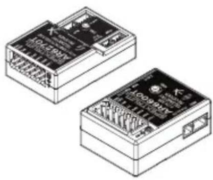
AR6600T/AR6270T Telemetry Receiver
The Spektrum™ AR6600T/AR6270T receivers are full range telemetry receivers featuring DSM® technology and are compatible with all Spektrum™ and JR® aircraft radios that support DSM2® and DSMX® technology.
These telemetry receivers features 4 integrated telemetry ports that are compatible with Spektrum telemetry capable transmitters.
For information on Spektrum Telemetry Sensors visit: http://www.spektrumrc.com
natural_image
Two identical electronic device modules with visible internal wiring and ports (no text or symbols)| AR6600T AR6270T | ||
| Type | DSMX with internal telemetry | DSMX Carbon Fuse with internal telemetry |
| Dimensions (LxWxH) | 37.5 x 27.7 x 15.8mm 44.2 x 27.90 x 14.8mm | |
| Antenna Length Dual- | 2.5 & 5 in Dual- 7 in | |
| Remote Antenna Yes-Included No | ||
| Channels 6 | ||
| Weight 12.5g 13.2g | ||
| Band 2.4GHz | ||
| Voltage Range 3.5–9V | ||
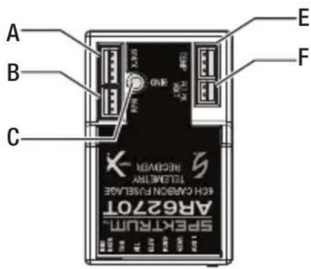
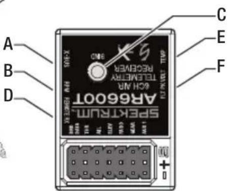
A: XBUS Port
B: RPM sensor port
C: Bind Button
D: Remote Rx port (6600T only)
E: Temperature sensor port
F: Voltage sensor port
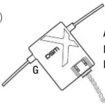
G: Remote Rx (6600T only)
AR6600T Receiver Installation
For optimum RF link performance it's important that the antennas be mounted in an orientation that allows for the best possible signal reception when the aircraft is in all possible attitudes and positions. This is known as antenna polarization. The antennas should be oriented perpendicular to each other; typically vertical and horizontal and at different angles. The remote receiver antenna should be mounted in a position perpendicular and at least 2 inches away from the main receiver's antenna using double-sided foam tape.
AR6270T Carbon Fuse Receiver Installation
Airplanes with significant carbon fiber construction can create an RF shielding effect, reducing range. The AR6270T is designed to overcome these critical RF issues in carbon airplanes by outfitting the aircraft with two external antennas at specific points that will ensure secure RF coverage from all angles of the aircraft.
The AR6270T incorporates two 7-inch feeder antennas, which are designed to be easily mounted through the fuselage in carbon airplanes. Each feeder antenna includes a coaxial portion (which can be thought of as an extension) and an exposed 31mm tip antenna. The last 31mm is the active portion of the antenna.

Installing the Receiver
Install the receiver in the normal position recommended by the airplane's manufacturer. Double-sided tape or foam can be used to secure the receiver in place.
Tip: The hard case can be removed to help the AR6270T fit into a slim, carbon fuselage. It is recommended to cover the bare receiver in heat shrink.
Mounting the Antennas
To install the antennas, drill two 1/16-inch holes in the desired antenna mounting positions.
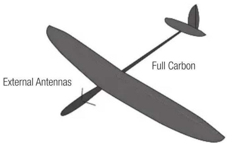
Slide the feeder antennas through the holes until the 31mm tip, and about 2mm of coaxial, completely exit the fuselage. Use a drop of CA or tape to fix the antenna to the fuselage.
IMPORTANT: Ensure that the 31mm active portion of each antenna tip is fully exposed.
TIP: Use the optional (sold separately) Antenna Exit Guides (SPM6824) to safely mount the antennas outside of the fuselage.
IMPORTANT: If the antenna is to be mounted internally (in the front of a 2.4GHz fuse), the coaxial can be taped into position. Ensure the 31mm tip is located at least 2 inches from any significant carbon structure.
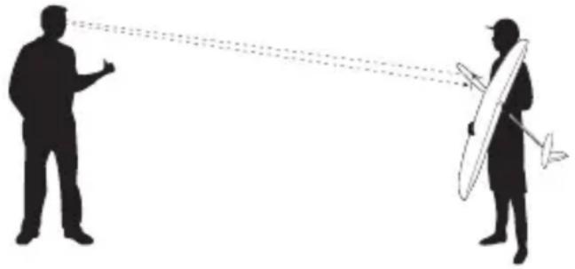
Check that at least one antenna will always be in the RF visual line of sight of the transmitter (e.g. not blocked by carbon fiber structures) in all attitudes. This can easily be visualized by having a helper stand about 20 feet away and rotate the airplane in all attitudes, confirming that there is a direct line between you and at least one receiver antenna that isn't blocked by carbon fiber structure.
natural_image
Silhouette of two figures interacting, one pointing and the other aiming a dart (no text or symbols)Binding
The AR6600T/AR6270T receivers must be bound to the transmitter before they will operate. Binding is the process of teaching the receiver the specific code of the transmitter so it will only connect to that specific transmitter.
- Connect the remote receiver (6600T only) and any telemetry sensors to the main receiver.
- Push and hold the bind button on the receiver while powering up the receiver. Release the Bind button once the orange LED starts to flash continuously, indicating that the receiver is in bind mode.
Tip: It is still possible to use a bind blug in the BIND/BATT port if desired.
- Put your transmitter in bind mode.
- The bind process is complete when the orange LED on the receiver is solid.
NOTICE: If using a bind plug, remove after binding to prevent the system from entering bind mode the next time the power is turned on.
- After you set up your model, always rebind the transmitter and receiver to set the desired failsafe positions. See FAILSAFE on the next page.
Failsafe
Failsafe position is set during binding. In the unlikely event that the radio link is lost during use, the receiver will drive all channels to its pre-programmed failsafe position.
SmartSafe + Hold Last
(AR6600T only)
If loss of signal occurs, SmartSafe technology moves the throttle channel to its preset failsafe position (low throttle) that was set during binding. All other channels hold their last position. When the receiver detects signal from the transmitter, normal aircraft operation resumes.
Preset Failsafe
(AR6600T and AR6270T)
Preset failsafe is ideal for sailplanes, allowing the aircraft to automatically dethermalize if the signal is lost. With preset failsafe, all channels go to their preset failsafe positions if the signal is lost, preventing a flyaway. When the receiver detects signal from the transmitter, normal aircraft operation resumes.
Tip: Use either the built in BIND button OR a bind blug in the BIND/BATT port.
| SmartSafe + Hold Last | AR6600T AR6270T | |
| 1 | Lower Throttle on transmitter NA | |
| 2 | Push and Hold Bind Button NA | |
| 3 | Power on Reciever NA | |
| 4 | Release Button once RX goes into Bind Mode (flashing LED) | NA |
| 5 | Place transmitter in Bind Mode and finish Binding. | |
| A* | Install bind plug (optional) NA | |
| B* | Leave in through entire bind process** NA | |
Preset Failsafe
| 1 | Move all sticks and switches on the transmitter to desired Failsafe position. | Move all sticks and switches on the transmitter to desired Failsafe position. |
| 2 | Push and Hold Bind Button Push and Hold Bind Button | |
| 3 | Power on Reciever Power on Reciever | |
| 4 | Release Button after RX goes into Bind Mode (flashing LED) | Release Button after RX goes into Bind Mode (flashing LED) |
| 5 | Push and Hold the Bind Button again before the transmitter enters Bind Mode. | Place transmitter in Bind Mode and finish Binding. |
| A* Install bind plug (optional) Install bind plug (optional) | ||
| B* | Remove plug once RX goes into Bind Mode | Leave in through entire bind process** |
*Setting Failsafe can be done with the Bind Plug if desired.
**Remove Bind Plug when finished setting up Failsafe.
Testing Failsafe
Secure the aircraft on the ground and remove the propellers. Test Failsafe by turning the transmitter off and noting how the receiver drives the control surfaces.
Receiver Power Only
- With SmartSafe or Preset Failsafe, when the receiver only is turned on (no transmitter signal is present), the throttle channel has no output, to avoid operating or arming the electronic speed control.
- All other channels have no output until the receiver has linked to the transmitter.
Range Testing
Before each flying session and especially with a new model, it is important to perform a range check. All Spektrum aircraft transmitters incorporate a range testing system which, when activated, reduces the output power, allowing a range check.
- With the model restrained on the ground, stand 30 paces (approx. 90 feet/28 meters) away from the model.
- Face the model with the transmitter in your normal flying position and place your transmitter into range check mode.
- You should have total control of the model with the button depressed at 30 paces (90 feet/28 meters).
- If control issues exist, contact the appropriate product support department.
Advanced Range Testing
For sophisticated models that have significant conductive material in them, the Advanced range test using a flight log is recommended. The advanced range check will confirm that the internal and remote receivers are operating optimally and that the installation (position of the receivers) is optimized for the specific aircraft. This Advanced Range Check allows the RF performance of each receiver to be evaluated and to optimize the locations of the remote receiver.
IMPORTANT: If you don't have a telemetry-capable transmitter, you can connect a Flight Log to the Bind/Prog port on the receiver.
- Standing 30 paces away from the model, face the model with the transmitter in your normal flying position.
- Put your transmitter in range test mode. Range test mode reduces the power output from the transmitter.
- Have someone position the model in various orientations (nose up, nose down, nose toward the transmitter, nose away from the transmitter, etc.).
- Observe the telemetry on your transmitter. Note any orientations that cause higher fade or hold values. Perform this step for at least one minute.
- Re-position any remote receivers as necessary.
Receiver Power System Requirements
Inadequate power systems that are unable to provide the necessary minimum voltage to the receiver during flight have become the number one cause of in-flight failures. Some of the power system components that affect the ability to properly deliver adequate power include:
- Receiver battery pack (number of cells, capacity, cell type, state of charge)
- The ESC's capability to deliver current to the receiver in electric aircraft
- The switch harness, battery leads, servo leads, regulators etc.
The AR6600T/AR6270T has a minimum operational voltage of 3.5 volts; it is highly recommended the power system be tested per the guidelines below.
Recommended Power System Test Guidelines
If a questionable power system is being used (e.g. small or old battery, ESC that may not have a BEC that will support high-current draw, etc.), it is recommended that a voltmeter be used to perform the following tests.
The Hangar 9 ^® Digital Servo & Rx Current Meter (HAN172) or the Spektrum Flight Log (SPM9540) is the perfect tool to perform the test below.
Plug the voltmeter into an open channel port in the receiver and with the system on, or simply monitor the voltage on a telemetry capable transmitter, load the control surfaces (apply pressure with your hand) while monitoring the voltage at the receiver. The voltage should remain above 4.8 volts even when all servos are heavily loaded.
How QuickConnect™ Techonlogy Works
- When the receiver voltage drops below 3.5 volts the system ceases to operate.
- When power is restored the receiver immediately attempts to reconnect.
- If the transmitter was left on, the system reconnects typically in about 4/100 of a second.
QuickConnect with Brownout Detection is designed to allow you to fly safely through most short duration power interruptions, however, the root cause of these interruptions must be corrected before the next flight to prevent a crash.
NOTICE: If a brownout occurs in flight it is vital that the cause of the brownout be determined and corrected.
Important: Y-Harnesses and Servo Extensions
When using a Y-harness or servo extensions in your installation, it's important to use standard non-amplified Y-harnesses and servo extensions as this can/will cause the servos to operate erratically or not function at all. Amplified Y-harnesses were developed several years ago to boost the signal for some older PCM systems and should not be used with Spektrum equipment.
Note that when converting an existing model to Spektrum be certain that all amplified Y-harnesses and/or servo extensions are replaced with conventional non-amplified versions.
ModelMatch™ Technology
Some Spektrum and JR transmitters offer a patent pending feature called ModelMatch. ModelMatch prevents the possibility of operating a model using the wrong model memory, potentially preventing a crash. With ModelMatch, each model memory has its own unique code (GUID) and during the binding process the code is programmed into the receiver. Later, when the system is turned on, the receiver will only connect to the transmitter if the corresponding model memory is programmed on screen.
If at any time you turn on the system and it fails to connect, check to be sure the correct model memory is selected in the transmitter. Please note that the DX5e and Aircraft Modules do not have ModelMatch.
Frequently Asked Questions on Spektrum 2.4GHz
- Q: After I've bound the receiver to my transmitter, which do I turn on first when I want to fly?
A: Either one. Every DSM 2.4GHz transmitter has a GUID (Globally Unique Identifier) code imbedded in its signal. When you bind a DSM receiver to your transmitter, this GUID code is stored in the receiver. If you turn the receiver on before the transmitter, you don't have to worry about it responding to another transmitter. The receiver will go into failsafe mode while it waits for a signal from the transmitter with the same GUID code it has stored. See the Receiver Power Only section for more information. If a DSM transmitter is turned on first you can expect it to connect within 6 seconds of powering on the receiver.
- Q: Sometimes the system takes longer to connect or doesn't connect at all. Why?
A: In order for a DSM system to connect, the receiver must receive a large number of uninterrupted signal packets from the transmitter. This process takes just a few seconds, but if the transmitter is too close to the receiver (within 4 feet) or near reflective material (metal objects, carbon fiber material, etc.) it may detect its own reflected 2.4GHz energy as “noise”. This can delay or prevent connection. If this happens, make sure you are a sufficient distance from metal objects and the receiver itself before you power up and try again.
- Q: How important is Flight Log information?
A: All 2.4GHz signals, not just DSM, are affected by proximity to conductive materials such as carbon fiber or metal. If you are flying a model that uses a lot of conductive materials in its construction, Flight Log information can be helpful. The information collected when you fly can help determine the optimum location for your receiver(s) so you can minimize the effects of these materials on your signal performance.
1-Year Limited Warranty
What this Warranty Covers - Horizon Hobby, LLC, (Horizon) warrants to the original purchaser that the product purchased (the "Product") will be free from defects in materials and workmanship for a period of 1 year from the date of purchase.
What is Not Covered
This warranty is not transferable and does not cover (i) cosmetic damage, (ii) damage due to acts of God, accident, misuse, abuse, negligence, commercial use, or due to improper use, installation, operation or maintenance, (iii) modification of or to any part of the Product, (iv) attempted service by anyone other than a Horizon Hobby authorized service center, (v) Product not purchased from an authorized Horizon dealer, (vi) Product not compliant with applicable technical regulations, or (vii) use that violates any applicable laws, rules, or regulations.
OTHER THAN THE EXPRESS WARRANTY ABOVE, HORIZON MAKES NO OTHER WARRANTY OR REPRESENTATION, AND HEREBY DISCLAIMS ANY AND ALL IMPLIED WARRANTIES, INCLUDING, WITHOUT LIMITATION, THE IMPLIED WARRANTIES OF NON-INFRINGEMENT, MERCHANTABILITY AND FITNESS FOR A PARTICULAR PURPOSE. THE PURCHASER ACKNOWLEDGES THAT THEY ALONE HAVE DETERMINED THAT THE PRODUCT WILL SUITABLY MEET THE REQUIREMENTS OF THE PURCHASER'S INTENDED USE.
Purchaser's Remedy
Horizon's sole obligation and purchaser's sole and exclusive remedy shall be that Horizon will, at its option, either (i) service, or (ii) replace, any Product determined by Horizon to be defective. Horizon reserves the right to inspect any and all Product(s) involved in a warranty claim. Service or replacement decisions are at the sole discretion of Horizon. Proof of purchase is required for all warranty claims. SERVICE OR REPLACEMENT AS PROVIDED UNDER THIS WARRANTY IS THE PURCHASER'S SOLE AND EXCLUSIVE REMEDY.
Limitation of Liability
HORIZON SHALL NOT BE LIABLE FOR SPECIAL, INDIRECT, INCIDENTAL OR CONSEQUENTIAL DAMAGES, LOSS OF PROFITS OR PRODUCTION OR COMMERCIAL LOSS IN ANY WAY, REGARDLESS OF WHETHER SUCH CLAIM IS BASED IN CONTRACT, WARRANTY, TORT, NEGLIGENCE, STRICT LIABILITY OR ANY OTHER THEORY OF LIABILITY, EVEN IF HORIZON HAS BEEN ADVISED OF THE POSSIBILITY OF SUCH DAMAGES. Further, in no event shall the liability of Horizon exceed the individual price of the Product on which liability is asserted. As Horizon has no control over use, setup, final assembly, modification or misuse, no liability shall be assumed nor accepted for any resulting damage or injury. By the act of use, setup or assembly, the user accepts all resulting liability. If you as the purchaser or user are not prepared to accept the liability associated with the use of the Product, purchaser is advised to return the Product immediately in new and unused condition to the place of purchase.
Law
These terms are governed by Illinois law (without regard to conflict of law principals). This warranty gives you specific legal rights, and you may also have other rights which vary from state to state. Horizon reserves the right to change or modify this warranty at any time without notice.
WARRANTY SERVICES
Questions, Assistance, and Services
Your local hobby store and/or place of purchase cannot provide warranty support or service. Once assembly, setup or use of the Product has been started, you must contact your local distributor or Horizon directly. This will enable Horizon to better answer your questions and service you in the event that you may
need any assistance. For questions or assistance, please visit our website at www.horizonhobby.com, submit a Product Support Inquiry, or call the toll free telephone number referenced in the Warranty and Service Contact Information section to speak with a Product Support representative.
Inspection or Services
If this Product needs to be inspected or serviced and is compliant in the country you live and use the Product in, please use the Horizon Online Service Request submission process found on our website or call Horizon to obtain a Return Merchandise Authorization (RMA) number. Pack the Product securely using a shipping carton. Please note that original boxes may be included, but are not designed to withstand the rigors of shipping without additional protection. Ship via a carrier that provides tracking and insurance for lost or damaged parcels, as Horizon is not responsible for merchandise until it arrives and is accepted at our facility. An Online Service Request is available at http://www.horizonhobby.com/content/service-center_render-service-center. If you do not have internet access, please contact Horizon Product Support to obtain a RMA number along with instructions for submitting your product for service. When calling Horizon, you will be asked to provide your complete name, street address, email address and phone number where you can be reached during business hours. When sending product into Horizon, please include your RMA number, a list of the included items, and a brief summary of the problem. A copy of your original sales receipt must be included for warranty consideration. Be sure your name, address, and RMA number are clearly written on the outside of the shipping carton.
NOTICE: Do not ship LiPo batteries to Horizon. If you have any issue with a LiPo battery, please contact the appropriate Horizon Product Support office.
Warranty Requirements
For Warranty consideration, you must include your original sales receipt verifying the proof-of-purchase date. Provided warranty conditions have been met, your Product will be serviced or replaced free of charge. Service or replacement decisions are at the sole discretion of Horizon.
Non-Warranty Service
Should your service not be covered by warranty, service will be completed and payment will be required without notification or estimate of the expense unless the expense exceeds 50% of the retail purchase cost. By submitting the item for service you are agreeing to payment of the service without notification. Service estimates are available upon request. You must include this request with your item submitted for service. Non-warranty service estimates will be billed a minimum of 12 hour of labor. In addition you will be billed for return freight. Horizon accepts money orders and cashier's checks, as well as Visa, MasterCard, American Express, and Discover cards. By submitting any item to Horizon for service, you are agreeing to Horizon's Terms and Conditions found on our website http://www.horizonhobby.com/content/service-center_render-service-center.
ATTENTION: Horizon service is limited to Product compliant in the country of use and ownership. If received, a non-compliant Product will not be serviced. Further, the sender will be responsible for arranging return shipment of the un-serviced Product, through a carrier of the sender's choice and at the sender's expense. Horizon will hold non-compliant Product for a period of 60 days from notification, after which it will be discarded.
Warranty and Service Contact Information
| Country of Purchase | Horizon Hobby Contact Information Address | ||
| United States of America | Horizon Service Center (Repairs and Repair Requests) | servicecenter.horizonhobby.com/RequestForm/ | 4105 Fieldstone Rd Champaign, Illinois, 61822 USA |
| Horizon Product Support (Product Technical Assistance) | productsupport@horizonhobby.com. | ||
| 877-504-0233 | |||
| Sales | websales@horizonhobby.com | ||
| 800-338-4639 | |||
| United Kingdom | Service/Parts/Sales: Horizon Hobby Limited | sales@horizonhobby.co.uk | Units 1–4, Ployters Rd, Staple Tye, Harlow Essex, CM18 7NS United Kingdom |
| +44 (0) 1279 641 097 | |||
| Germany | Horizon Technischer Service | service@horizonhobby.de | Christian-Junge-Straße 1 25337 Elmshorn, Germany |
| Sales: Horizon Hobby GmbH | +49 (0) 4121 2655 100 | ||
| France | Service/Parts/Sales: Horizon Hobby SAS | infofrance@horizonhobby.com | 11 Rue Georges Charpak 77127 Lieusaint, France |
| +33 (0) 1 60 18 34 90 | |||
FCC Information
This equipment has been tested and found to comply with the limits for a Class B digital device, pursuant to part 15 of the FCC Rules. These limits are designed to provide reasonable protection against harmful interference in a residential installation. This equipment generates, uses and can radiate radio frequency energy and, if not installed and used in accordance with the instructions, may cause harmful interference to radio communications.
However, there is no guarantee that interference will not occur in a particular installation. If this equipment does cause harmful interference to radio or television reception, which can be determined by turning the equipment off and on, the user is encouraged to try to correct the interference by one or more of the following measures:
Reorient or relocate the receiving antenna.
Increase the separation between the equipment and receiver.
Connect the equipment to an outlet on a circuit different from that to which the receiver is connected.
This device complies with part 15 of the FCC rules. Operation is subject to the following two conditions: (1) This device may not cause harmful interference, and (2) this device must accept any interference received, including interference that may cause undesired operation.
Notice: Modifications to this product will void the user's authority to operate this equipment.
This product contains a radio transmitter with wireless technology which has been tested and found to be compliant with the applicable regulations governing a radio transmitter in the 2.400GHz to 2.4835GHz frequency range.
IC Information
This device complies with Industry Canada license-exempt RSS standard(s). Operation is subject to the following two conditions: (1) this device may not cause interference, and (2) this device must accept any interference, Including interference that may cause undesired operation of the device.
Compliance Information for the European Union

Horizon Hobby, LLC hereby declares that this product is in compliance with the essential requirements and other relevant provisions of the RED Directive.
A copy of the EU Declaration of Conformity is available online at:
http://www.horizonhobby.com/content/support-render-compliance.
Instructions for Disposal of WEEE by Users in the European Union
This product must not be disposed of with other waste. Instead, it is the user's responsibility to dispose of their waste equipment by handing it over to a designated collection point for the recycling of waste electrical and electronic equipment. The separate collection and recycling of your waste equipment at the time of disposal will help to conserve natural resources and ensure that it is recycled in a manner that protects human health and the environment. For more information about where you can drop off your waste equipment for recycling, please contact your local city office, your household waste disposal service or where you purchased the product.

E328

SPEKTRUM®
© 2016 Horizon Hobby, LLC.
DSM, DSM2, DSMX, QuickConnect, ModelMatch, SmartSafe, Hangar 9 and the Horizon Hobby logo are trademarks or registered trademarks of Horizon Hobby, LLC.
The Spektrum trademark is used with permission of Bachmann Industries, Inc.
JR is a registered trademark of JR Americas. All other trademarks, service marks and logos are property of their respective owners.
US 7,391,320. Other patents pending.
Created 08/16 52911
SPMAR6600T, SPMAR6270T

- Meaning of Special Language
- WARNING AGAINST COUNTERFEIT PRODUCTS
- WARRANTY REGISTRATION
- AR6600T/AR6270T Telemetry Receiver
- AR6600T Receiver Installation
- AR6270T Carbon Fuse Receiver Installation
- Installing the Receiver
- Mounting the Antennas
- Binding
- Failsafe
- SmartSafe + Hold Last
- Preset Failsafe
- Testing Failsafe
- Receiver Power Only
- Range Testing
- Advanced Range Testing
- Receiver Power System Requirements
- Recommended Power System Test Guidelines
- How QuickConnect™ Techonlogy Works
- Important: Y-Harnesses and Servo Extensions
- ModelMatch™ Technology
- Frequently Asked Questions on Spektrum 2.4GHz
- 1-Year Limited Warranty
- What is Not Covered
- Purchaser's Remedy
- Limitation of Liability
- Law
- WARRANTY SERVICES
- Questions, Assistance, and Services
- Inspection or Services
- Warranty Requirements
- Non-Warranty Service
- Warranty and Service Contact Information
- FCC Information
- IC Information
- Compliance Information for the European Union
- Instructions for Disposal of WEEE by Users in the European Union
- SPEKTRUM®
Brand : SPEKTRUM
Model : AR6600T
Category : Remote control toy