RY31DP18 - Pump RYOBI - Free user manual and instructions
Find the device manual for free RY31DP18 RYOBI in PDF.
| Product Type | Drill Pump |
| Brand | RYOBI |
| Model | RY31DP18 |
| Max Drilling Speed | 2,800 RPM |
| Maximum Head Height | 10.7 m (35 ft) |
| Maximum Lift | 3.0 m (10 ft) |
| Inlet/Outlet Connection | 19.1 mm male GHT |
| Intended Use | Remove water from flooded areas, clogged sinks, basins |
| Inlet Hose Included | 91.44 cm (36 in) |
| Power Source | Electric or cordless drill (not included) |
| Chuck Type | 6.35 mm hex shank |
| Weight (pump only) | Approximately 0.5 kg |
| Material | Plastic, rubber O-ring |
| Cleaning | Dry cloth only, avoid solvents |
| Routine Maintenance | Replace impeller and O-ring |
| Safety | Do not pump flammable liquids; use with water only; disconnect drill before maintenance |
| Spare Parts | Available at www.ryobitools.com or at 1-800-525-2579 |
| Number of pages in the manual | 22 |
Frequently Asked Questions - RY31DP18 RYOBI
User questions about RY31DP18 RYOBI
0 question about this device. Answer the ones you know or ask your own.
Ask a new question about this device
Download the instructions for your Pump in PDF format for free! Find your manual RY31DP18 - RYOBI and take your electronic device back in hand. On this page are published all the documents necessary for the use of your device. RY31DP18 by RYOBI.
USER MANUAL RY31DP18 RYOBI
WARNING: To reduce the of injury, the user must read and understand the operator's manual use using this product.
SAVE THIS MANUAL FOR FUTURE REFERENCE
TABLE DES MATIÈRES
See this fold-out section for all the figures referenced in the operator's manual.
A - Water outlet (sortie d'eau, salida de agua)
B - Water inlet (entrée d'eau, entrada de agua)
C - Intake hose (tuyau d'admission, manguera de admisión)
Fig. 2 Fig. 3
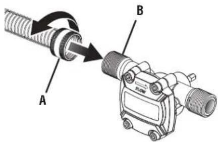
A-Intake hose (tuyau d'admission, manguera de admisión)
B-Water inlet (entrée d'eau, entrada de agua)
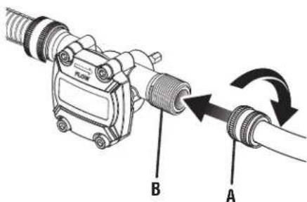
A -Garden hose (not included) [boyau d'arrosage (non inclus), manguera de jardín (no incluida)]
B - Water outlet (sortie d'eau, salida de agua)
Fig. 4
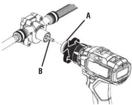
A-Drill chuck (mandrin, portabrocas del taladro)
B - Drill bit (foret, broca)
Fig. 5
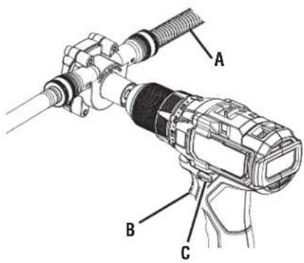
A-Intake hose (tuyau d'admission, manguera de admisión)
B- Switch trigger (gâchette de commutateur, gatillo del interruptor)
IMPORTANT SAFETY INSTRUCTIONS

WARNING!
READ AND SAVE THESE INSTRUCTIONS. Failure to follow all instructions listed below, may result in electric shock, fire and/or serious personal injury.

WARNING:
Follow all safety instructions recommended by the drill manufacturer.
Save all warnings and instructions for future reference. The term “product” in the warnings refers to your mains-operated (corded) product or battery-operated (cordless) product.
WORK AREA SAFETY
- Keep your work area clean and well lit. Cluttered benches and dark areas invite accidents.
■ Do not operate products in explosive atmospheres, such as in the presence of flammable liquids, gases or dust. Products create sparks which may ignite the dust or fumes. - Keep children and bystanders away while operating a product. Distractions can cause you to lose control.
ELECTRICAL SAFETY
■ Risk of explosion or fire. Never pump flammable or explosive liquids such as gasoline or kerosene.
■ Disconnect the drill from the pump when not in use.
■ Unplug the drill or remove the drill battery before attempting to service the pump.
■ Risk of electric shock. Keep hands, feet, and drill dry. Using a wet drill could result in fatal electric shock.
■ Risk of electric shock. When operating with an AC powered drill, ensure it is always grounded to an acceptable electrical outlet. Use only double insulated drill or a drill with a 3-wire grounded power plug. Always connect drill to an outlet equipped with ground fault circuit interrupter (GFCI) protection.
PERSONAL SAFETY
■ Do not overreach. Keep proper footing and balance at all times. Proper footing and balance enable better control of the product in unexpected situations.
■ Do not use on a ladder or unstable support. Stable footing on a solid surface enables better control of the product in unexpected situations.
■ Prevent unintentional starting. Ensure the switch is in the off-position before connecting to power source and/or battery pack, picking up or carrying the tool. Carrying power tools with your finger on the switch or energizing power tools that have the switch on invites accidents.
DRILL PUMP USE AND CARE
■ Check hoses before using pump. Replace if worn or damaged.
■ Ensure all hose connections are tight before using pump.
■ CAUTION: The pump has been evaluated for use with water only. Do not use with acids, alkalines, solvents, flammable material, gasoline or petroleum products, bleaches or industrial grade solutions. These products can cause physical injuries to the operator and irreversible damage to the pump.
■ Disconnect the drill from the pump before making any adjustments, changing accessories, or storing the product. Such preventive safety measures reduce the risk of starting the product accidentally.
■ Release the pressure and drain water from the pump before servicing or before putting in storage.
- Keep the product and its hose dry, clean and free from oil and grease. Always use a clean cloth when cleaning. Never use brake fluids, gasoline, petroleum-based products, or any strong solvents to clean your product. Following this rule will reduce the risk of loss of control and deterioration of the enclosure plastic.
■ Clean only with dry cloth.
■ Do not operate near any heat sources such as radiators, heat registers, stoves or other apparatus (including amplifiers) that produce heat.
SERVICE
■ Product service must be performed only by qualified repair personnel. Service or maintenance performed by unqualified personnel may result in a risk of injury.
■ When servicing the product, use only identical replacement parts. Follow instructions in the Maintenance section of this manual. Use of unauthorized parts or failure to follow Maintenance Instructions may create a risk of shock or injury.
PUMP SAFETY WARNINGS
- Know your product. Read operator's manual carefully. Learn its applications and limitations, as well as the specific potential hazards related to this product. Following this rule will reduce the risk of electric shock, fire, or serious injury.
■ Do not permit children to use pump. It is not a toy.
■ Do not let the pump run dry.
■ Do not lift the pump by the cord or hoses.
■ Periodically inspect the pump and hoses. Ensure hoses are free from mud, sand and debris. Disconnect the battery before inspecting.
■ Save these instructions. Refer to them frequently and use them to instruct others who may use this tool. If you loan someone this tool, loan them these instructions also.
SYMBOLS
| The following signal words and meanings are intended to explain the levels of risk associated with this product. SYMBOL SIGNAL MEANING | ||
 | DANGER: | Indicates a hazardous situation, which, if not avoided, will result in death or serious injury. |
 | WARNING: | Indicates a hazardous situation, which, if not avoided, could result in death or serious injury. |
 | CAUTION: | Indicates a hazardous situation, that, if not avoided, may result in minor or moderate injury. |
| NOTICE: | (Without Safety Alert Symbol) Indicates information considered important, but not related to a potential injury (e.g. messages relating to property damage). | |
| Some of the following symbols may be used on this product. Please study them and learn their meaning. Proper interpretation of these symbols will allow you to operate the product better and safer. SYMBOL NAME DESIGNATION/EXPLANATION | ||
 | Safety Alert Indicates a potential personal injury hazard. | |
 | Read Operator's Manual | To reduce the risk of injury, user must read and understand operator's manual before using this product. |
 | Wet Conditions Alert | Do not expose to rain or use in damp locations. |
 | Risk of Explosion | Do not pump flammable liquids. Flammable liquids and their vapors are explosive and can cause severe burns or death. |
 | Electric Shock | To reduce the risk of electrocution or electric shock, keep away from water and do not use with damaged power cord. |
 | Wear Gloves Wear non-slip, heavy-duty protective gloves when handling this equipment. | |
 | Recycle Symbol | This product uses lithium-ion (Li-ion) batteries. Local, state or federal laws may prohibit disposal of batteries in ordinary trash. Consult your local waste authority for information regarding available recycling and/or disposal options. |
SYMBOLS
| Some of the following symbols may be used on this product. Please study them and learn their meaning. Proper interpretation of these symbols will allow you to operate the product better and safer. SYMBOL NAME DESIGNATION/EXPLANATION | ||
| V Volts Voltage | ||
| Hz Hertz Frequency (cycles per second) | ||
| W Watt Power | ||
| min | Minutes | Time |
| --- | Direct Current Type or a characteristic of current | |
| VI | Class VI Tool | DOE certification |
FEATURES
PRODUCT SPECIFICATIONS
Max. Drill Speed....2,800/min
Flow rates.....2,800 RPM: 10 GPM / 2,000 RPM: 8.5 GPM
Max Head Height 35 ft.
Max Lift Height 10 ft.
Inlet/Outlet Connection 3/4 in. GHT male
ASSEMBLY
UNPACKING
This product requires assembly.
■ Carefully remove the tool and any accessories from the box. All items listed in the Includes section must be included at the time of purchase.

WARNING:
Items in this Assembly section are not assembled to the product by the manufacturer and require customer installation. Use of a product that may have been improperly assembled could result in serious personal injury.
■ If any parts are damaged or missing, please call 1-800-525-2579 for assistance.

WARNING:
If any parts are damaged or missing do not operate this product until the parts are replaced. Use of this product with damaged or missing parts could result in serious personal injury.

WARNING:
Do not attempt to modify this product or create accessories or attachments not recommended for use with this product. Any such alteration or modification is misuse and could result in a hazardous condition leading to possible serious personal injury.
PACKING LIST
Drill Pump
3 ft. Intake Hose
OPERATION

WARNING:
Do not allow familiarity with products to make you careless. Remember that a careless fraction of a second is sufficient to inflict serious injury.

WARNING:
When using with an AC powered drill, always ensure the drill is properly grounded and plugged into a GFCI protected outlet.

WARNING:
Risk of electric shock, serious personal injury, or death. When connected to a drill, never touch pump with wet hands or when standing on a wet surface.

WARNING:
Keep water discharge pointed away from all electrical devices to reduce the risk of electrocution or electric shock.

WARNING:
Ensure all hose connections are secure before using the drill pump. Spilled water and leaks can result in a slippery surface and create a slip and fall hazard.

WARNING:
Do not use any attachments or accessories not recommended by the manufacturer of this product. The use of attachments or accessories not recommended can result in serious personal injury.

WARNING:
Always remove battery pack or unplug power cord from your product when you are assembling parts, making adjustments, cleaning, or when not in use. Removing battery pack or unplugging power cord will prevent accidental starting that could cause serious personal injury.
APPLICATIONS
You may use this tool for the purpose listed below:
- Drain or remove water from flooded areas, clogged sinks, water basins, water heaters, swimming pools, etc.
Do not use a drill that exceeds 2,800 max RPM.
The drill pump connects to an electric drill, cordless drill or impact driver using a 1/4 in. hex shank connection.
■ Remove battery pack or disconnect the drill from a power supply.
■ Inspect the gasket in the suction hose to ensure it is in good condition and properly installed in the hose.
■ Follow the steps in Priming the Pump section for best priming results.
■ Connect the supplied suction hose to the water inlet on the pump.
■ Connect a heavy duty garden hose to the water outlet on the pump.
■ Attach the drill pump and connected hoses to the drill.
■ Tighten the drill chuck onto the bit located on the back of the pump.
PREPARING THE PUMP FOR USE
See Figures 4 and 5.
■ Inspect hoses prior to use to be sure both are in good condition and are securely connected.
■ Make sure the intake hose is submerged in the liquid and is air tight.
■ Direct the discharge hose away from the area being pumped or into a suitable container.
■ Make sure the direction of rotation of the drill is in the forward setting.
NOTE: When drill operates in reverse, the suction and outlet are reversed.
■ Ensure the intake hose is not pinched or kinked.
NOTE: Firmly grasp the drill in one hand and the intake hose in the other while the pump is in use.
STARTING/STOPPING THE DRILL PUMP
See Figure 5.
To start the pump:
- Insert the drill's battery or connect the drill to a power supply.

WARNING:
Battery tools are always in operating condition, therefore the unit should always be in the OFF position, with the battery pack removed, when not in use. Do not leave pump on while unattended. Failure to follow these instructions could result in serious personal injury.
OPERATION

WARNING:
Always install the hoses before operating the unit.
- Grip the intake hose to prevent any rotation due to starting/stopping torque.
■ Squeeze the switch trigger to start the drill.

WARNING:
Firmly hold the intake hose with a gloved hand while in operation.
To stop the pump:
■ Release the switch trigger of the drill.
- Remove the drill's battery, or disconnect the drill's power supply.
PRIMING THE PUMP
See Figure 6.
■ Add water to the water inlet side of the pump to prime the impeller.
NOTE: For best results, add water to the inlet to prime the pump. This step is not necessary but it will speed up the priming process.
■ Slowly start the drill, bringing it to full speed within a few seconds. The pump should self-prime within 10 seconds.
NOTE: If the pump does not prime, make sure there are no obstructions or leaks in the inlet hose.
MAINTENANCE

WARNING:
When servicing, use only identical replacement parts. Use of any other parts could create a hazard or cause product damage.
STORING THE DRILL PUMP
Store indoors in a dry, locked-up place out of the reach of children, with the pump disconnected from the drill and all hoses. Keep away from corrosive agents such as garden chemi cals and de-icing salts.
GENERAL MAINTENANCE
Avoid using solvents when cleaning plastic parts. Most plastics are susceptible to damage from various types of commercial solvents and may be damaged by their use. Use clean cloths to remove dirt, dust, oil, grease, etc.
REPLACING THE IMPELLER AND O-RING
See Figures 7 - 8.
■ Disconnect the pump from the drill and hoses.
- Locate and remove the four screws from the impeller plate cover.
- Carefully remove pump cover and inspect o-ring for damage or wear. If o-ring is damaged or worn, replace o-ring.
NOTE: Be sure to keep the pump cover and glass plate together in the same order for installation.
■ Remove old impeller and replace with new impeller, lining up the key on the shaft. After insertion, the impeller should be resting flat against the back wall of the pump body, as the original impeller was.
■ Make sure o-ring is properly seated and assemble pump cover and glass plate.
■ Assemble the four screws and hand tighten only. Refer to Starting/Stopping the Drill Pump and check to make sure the impeller plate does not leak.
Register your product: www.ryobitools.com or call toll-free 1-800-525-2579
This product has a One-year Warranty.
TROOBERATION
PROBLEM POSSIBLECAUSEPOSSIBLE SOLUTION
| Not pumping water Impeller blockage. | SeeReplacing the Impeller and O-Ringin the Maintenance section of this manual. |
| Outlet line positioned too high. | Lower the outlet hose height to below the height listed in the Product Specifications. |
| Outlet line is too long. | Use a shorter length of outlet line if possible. |
| Flow rate is too low Inlet/Outlet line is clogged or damaged. | Replace Inlet/Outlet line. Check lines for blockages, kinks or bends. Clear blockages. |
| Inlet connection not air tight. | Tighten inlet connection. Add pipe thread tape or a gasket if necessary. |
| Impeller cover is not secured tightly. | Hand tighten four (4) cover screws. |
| Impeller worn out. | SeeReplacing the Impeller and O-Ringin the Maintenance section of this manual. |
INSTRUCTIONS IMPORTANTES CONCERNANT LA SÉCURITÉ

AVERTISSEMENT !
Débit....2 800 RPM: 10 GPM / 2 000 RPM: 8,5 GPM
PROBLÈME CAUSEPOSSIBLESOLUTION POSSIBLE
- PARTS AND SERVICE: Prior to requesting service or purchasing replacement parts, please obtain your item, manufacturing, and serial numbers from the product data plate.
ITEM NO.*
MANUFACTURING NO.
SERIAL NO.
* Model/item number on product may have additional letters at the end. These letters designate manufacturing information and should be provided when calling for service.
HOW TO OBTAIN REPLACEMENT PARTS: Replacement parts can be purchased online at www.ryobitools.com or by calling 1-800-525-2579. Replacement parts can also be obtained at one of our service centers.
HOW TO LOCATE A SERVICE CENTER: Service centers can be located online at www.ryobitools.com or by calling 1-800-525-2579.
HOW TO OBTAIN CUSTOMER OR TECHNICAL SUPPORT: To obtain customer or technical support please contact us at 1-800-525-2579.
RYOBI is a trademark of Ryobi Limited and is used pursuant to a license granted by Ryobi Limited.