One+ PCL001 - Pump RYOBI - Free user manual and instructions
Find the device manual for free One+ PCL001 RYOBI in PDF.

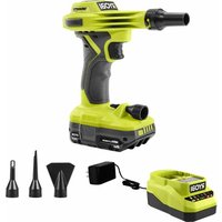
| Product Type | Cordless Inflator Pump |
| Brand | RYOBI |
| Model | One+ PCL001 |
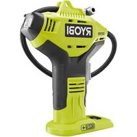
| Maximum Pressure | 160 PSI (11 bar) |
| Hose Length | 609.6 mm (24 in) |
| Duty Cycle | 5 minutes on / 5 minutes off |
| Display | Digital pressure gauge (PSI) |
| Power Source | RYOBI One+ Lithium-Ion Battery (18 V) |
| Applications | Inflating tires (motorcycle, car, bicycle), sports balls |
| Included Accessories | Tapered adapter, ball needle, Presta valve adapter, storage clip |
| Warranty | Limited 3 years |
| Safety | Do not exceed 160 PSI; duty cycle to avoid overheating; display auto-off after 5 min of inactivity |
| Maintenance and Cleaning | Clean with a clean cloth; do not use solvents |
| Spare Parts and Repairability | Parts available from Ryobi (1-800-525-2579); repairs by authorized center |
| Usage | Household use only |
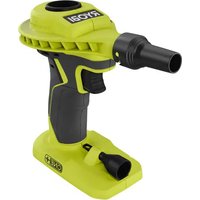
| General Information | Cordless inflator pump from the RYOBI One+ range; compatible with all One+ batteries and chargers |
Frequently Asked Questions - One+ PCL001 RYOBI
User questions about One+ PCL001 RYOBI
0 question about this device. Answer the ones you know or ask your own.
Ask a new question about this device
Download the instructions for your Pump in PDF format for free! Find your manual One+ PCL001 - RYOBI and take your electronic device back in hand. On this page are published all the documents necessary for the use of your device. One+ PCL001 by RYOBI.
USER MANUAL One+ PCL001 RYOBI
natural_image
Line drawing of a Ryobi industrial device with control panel and buttons (no text or symbols on body)TABLE OF CONTENTS
************************
■ General Safety Rules....2-3
■ Specific Safety Rules 3-4
Symbols......4-5
■ Features....5
■ Assembly....6
■ Operation....6-8
■ Maintenance....8
■ Illustrations....9-10
■ Parts Ordering
and Service ....Back page

WARNING: To reduce the
risk of injury, the user must read and understand the operator's manual before using this product.
SAVE THIS MANUAL FOR
FUTURE REFERENCE
TABLE DES MATIÈRES
************************
READ AND UNDERSTAND ALL INSTRUCTIONS. Failure to follow all instructions listed below, may result in electric shock, fire and/or serious personal injury.

WARNING!
When using electric appliances, basic precautions should always be followed, including the following:
SAVE THESE INSTRUCTIONS WORK AREA
- Keep your work area clean and well lit. Cluttered benches and dark areas invite accidents.
- Keep bystanders, children, and visitors away while operating an inflator. Distractions can cause you to lose control.
■ Operate inflator in an open area at least 18 in. away from any wall or object that could restrict the flow of fresh air to ventilation openings.
ELECTRICAL SAFETY
■ To reduce the risk of electrical shock, do not put inflator in water or other liquid. Do not place or store appliance where it can fall or be pulled into a tub or sink.
■ Use this product only with batteries and chargers listed in tool/appliance/battery pack/charger correlation supplement 987000-432.
PERSONAL SAFETY
■ Stay alert, watch what you are doing and use common sense when operating an inflator. Do not use inflator while tired or under the influence of drugs, alcohol, or medication. A moment of inattention while operating inflator may result in serious personal injury.
■ Dress properly. Do not wear loose clothing or jewelry. Contain long hair. Keep your hair and clothing away from moving parts. Loose clothes, jewelry, or long hair can be caught in moving parts.
■ Do not overreach. Keep proper footing and balance at all times. Proper footing and balance enable better control of the inflator in unexpected situations.
■ Use safety equipment. Always wear eye protection. Dust mask, non-skid safety shoes, hard hat, or hearing protection must be used for appropriate conditions.
■ Eye protection is required to guard against flying fasteners and debris which could cause severe eye injury.
■ Do not wear loose clothing or jewelry. Contain long hair. Loose clothes, jewelry, or long hair can be drawn into air vents.
■ Do not use on a ladder or unstable support. Stable footing on a solid surface enables better control of the inflator in unexpected situations.
■ Do not disassemble the inflator.
■ Do not operate inflator near flammable liquids or in gaseous or explosive atmospheres. Internal sparks may ignite fumes.
- Do not store your inflator in a damp or wet location. Do not store in locations where the temperature is less than 50°F or more than 100°F. Do not store in outside sheds or in vehicles.
INFLATOR USE AND CARE
■ Check hoses for weak or worn condition before each use, making certain all connections are secure. Do not use if defect is found. Purchase a new hose or notify an authorized service center for examination or repair.
■ Release all pressures within the system slowly. Dust and debris may be harmful.
- Do not use inflator if switch does not turn it on or off. An inflator that cannot be controlled with the switch is dangerous and must be repaired.
■ Switch the tool off before making any adjustments, changing accessories, or storing the inflator. Such preventive safety measures reduce the risk of starting the inflator accidentally.
■ Store idle inflators out of reach of children and other untrained persons. Inflators are dangerous in the hands of untrained users.
- Check for misalignment or binding of moving parts, breakage of parts, and any other condition that may affect the inflator's operation. If damaged, have the inflator serviced before using. Many accidents are caused by poorly maintained tools.
■ Use only accessories that are recommended by the manufacturer for your model. Accessories that may be suitable for one inflator may create a risk of injury when used on another inflator.
- Keep the inflator and its handle dry, clean and free from oil and grease. Always use a clean cloth when cleaning. Never use brake fluids, gasoline, petroleum-based products, or any strong solvents to clean your inflator. Following this rule will reduce the risk of loss of control and deterioration of the enclosure plastic.
■ Never point any inflator toward yourself or others.
GENERAL SAFETY RULES
- Keep the exterior of the inflator dry, clean, and free from oil and grease. Always use a clean cloth when cleaning. Never use brake fluids, gasoline, petroleum-based products, or any strong solvents to clean the unit. Following this rule will reduce the risk of deterioration of the enclosure plastic.
■ Do not exceed the pressure rating of any component in the system.
■ Protect material lines and air lines from damage or puncture. Keep hose and power cord away from sharp objects, chemical spills, oil, solvents, and wet floors.
■ Inflator service must be performed only by qualified repair personnel. Service or maintenance performed by unqualified personnel may result in a risk of injury.
■ When servicing an inflator, use only identical replacement parts. Follow instructions in the Maintenance section of this manual. Use of unauthorized parts or failure to follow Maintenance Instructions may create a risk of shock or injury.
SPECIFIC SAFETY RULES
- Know your inflator. Read operator's manual carefully. Learn its applications and limitations, as well as the specific potential hazards related to this tool. Following this rule will reduce the risk of electric shock, fire, or serious injury.
■ Risk of bursting. Do not operate inflator to result in output pressure greater than marked maximum pressure of item to be inflated. Do not use at pressure greater than 160 PSI.
■ To reduce the risk of electric shock, do not expose to rain. Store indoors.
■ Inspect unit for cracks, pin holes, or other imperfections that could cause inflator to become unsafe. Never cut or drill holes in the inflator.
■ Make sure the hose is free of obstructions or snags. Entangled or snarled hoses can cause loss of balance or footing and may become damaged.
■ Use the inflator only for its intended use. Do not alter or modify the unit from the original design or function.
■ Always be aware that misuse and improper handling of this inflator can cause injury to yourself and others.
■ Never leave an inflator unattended with the nozzle attached to the item being inflated.
■ Do not continue to use a inflator or nozzle that leaks air or does not function properly.
■ Always disconnect the battery pack before making adjustments, servicing an inflator, or when an inflator is not in use.
■ Do not attempt to pull or carry the inflator by the hoses.
■ Always follow all safety rules recommended by the manufacturer of your inflator, in addition to all safety rules for the inflator. Following this rule will reduce the risk of serious personal injury.
■ Household use only.
■ Do not use inflator as a breathing device.
■ Never direct a jet of compressed air toward people or animals. Take care not to blow dust and dirt towards yourself or others. Following this rule will reduce the risk of serious injury.
■ Protect your lungs. Wear a face or dust mask if the operation is dusty. Following this rule will reduce the risk of serious personal injury.
■ Do not use this inflator to spray chemicals. Your lungs can be damaged by inhaling toxic fumes.
- Check damaged parts. Before further use of the inflator or air tool, a guard or other part that is damaged should be carefully checked to determine that it will operate properly and perform its intended function.
- Check for alignment of moving parts, binding of moving parts, breakage of parts, mounting, and any other conditions that may affect its operation. A guard or other part that is damaged should be properly repaired or replaced by an authorized service center. Following this rule will reduce the risk of shock, fire, or serious injury.
■ Risk of bursting. Carefully monitor objects during inflation.
■ To reduce the risk of over inflation, use a reliable pressure gauge periodically during inflation.
■ Never leave the inflator unattended during inflation.
■ Never block the inflating or deflating outlets while operating.
■ Do not use a battery pack that is damaged or modified. Damaged or modified batteries may exhibit unpredictable behavior resulting in fire, explosion or risk of injury.
■ Do not modify or attempt to repair a battery pack that has been damaged.
- Do not expose a battery pack or appliance to fire or excessive temperature. Exposure to fire or temperature above 265°F may cause explosion.
SPECIFIC SAFETY RULES
■ Follow all charging instructions and do not charge the battery pack or appliance outside of the temperature range specified in the instructions. Charging improperly or at temperatures outside of the specified range may damage the battery and increase the risk of fire.
■ Have servicing performed by a qualified repair person using only identical replacement parts. This will ensure that the safety of the product is maintained.
- Allow pump to cool for five (5) minutes after each five (5) minutes of continuous use. Never block the inflating or deflating outlets while operating.
■ Save these instructions. Refer to them frequently and use them to instruct others who may use this inflator. If you loan someone this inflator, loan them these instructions also.
SYMBOLS
| The following signal words and meanings are intended to explain the levels of risk associated with this product. SYMBOL SIGNAL MEANING | ||
 | DANGER: | Indicates a hazardous situation, which, if not avoided, will result in death or serious injury. |
 | WARNING: | Indicates a hazardous situation, which, if not avoided, could result in death or serious injury. |
 | CAUTION: | Indicates a hazardous situation, that, if not avoided, may result in minor or moderate injury. |
| NOTICE: | (Without Safety Alert Symbol) Indicates information considered important, but not related to a potential injury (e.g. messages relating to property damage). | |
SYMBOLS
| Some of the following symbols may be used on this product. Please study them and learn their meaning. Proper interpretation of these symbols will allow you to operate the product better and safer. SYMBOL NAME DESIGNATION/EXPLANATION | ||
 | Safety Alert Indicates a potential | personal injury hazard. |
 | Read Operator's Manual | To reduce the risk of injury, user must read and understand operator's manual before using this product. |
 | Eye Protection | Always wear eye protection with side shields marked to comply with ANSI Z87.1. |
 | Wet Conditions Alert Do not expose to rain or use in damp locations. | |
 | Hot Surface | To reduce the risk of injury or damage, avoid contact with any hot surface. |
 | Risk of Bursting | Do not operate inflator to result in output pressure greater than marked maximum pressure of attachment. Do not use at pressure greater than 160 PSI. |
 | Recycle Symbol | This product uses lithium-ion (Li-ion) batteries. Local, state or federal laws may prohibit disposal of batteries in ordinary trash. Consult your local waste authority for information regarding available recycling and/or disposal options. |
| V Volts Voltage | ||
| min Minutes Time | ||
| == | Direct Current Type or a characteristic of current | |
| n_0 | No Load Speed Rotational speed, at no load | |
| .../min Per Minute Revolutions, strokes, surface speed, orbits etc., per minute | ||
FEATURES
PRODUCT SPECIFICATIONS
Hose Length....24 in.
Maximum Pressure....160 PSI
Duty Cycle 5 minutes On/5 minutes Off
Gauge...... Digital Readout (PSI)
ASSEMBLY
WARNING:
Do not use this product if it is not completely assembled or if any parts appear to be missing or damaged. Use of a product that is not properly and completely assembled or with damaged or missing parts could result in serious personal injury.
WARNING:
Do not attempt to modify this product or create accessories or attachments not recommended for use with this product. Any such alteration or modification is misuse and could result in a hazardous condition leading to possible serious personal injury.
If any parts are damaged or missing, please call 1-800-525-2579 for assistance.
OPERATION
WARNING:
Do not allow familiarity with this product to make you careless. Remember that a careless fraction of a second is sufficient to inflict serious injury.
WARNING:
Always wear eye protection with side shields marked to comply with ANSI Z87.1. Failure to do so could result in objects being thrown into your eyes resulting in possible serious injury.
WARNING:
Do not use any attachments or accessories not recommended by the manufacturer of this tool. The use of attachments or accessories not recommended can result in serious personal injury.
WARNING:
Do not leave items to be inflated unattended while inflator is in use. These items can burst and could cause serious injury.
NOTICE:
The inflator is not designed for continuous use. For every five minutes of inflator use, five minutes of cool down time are required.
WARNING:
Since the pressure gauge is not calibrated, and is therefore not binding for exact values, tire pressure must be checked using a reliable measuring device before driving a vehicle with vehicle tires inflated with the inflator. Driving a vehicle with improperly inflated tires could result in serious injury.
NOTICE:
The inflator is capable of inflating to 160 PSI. To avoid over inflation, carefully follow instructions on items to be inflated. To avoid product damage, never exceed recommended pressures.
APPLICATIONS
You may use this inflator for the purpose listed below:
■ Inflating items such as motorcycle, car, and bicycle tires
■ Inflating items such as sports balls
NOTE: The inflator is not designed for commercial applications.
WARNING:
Battery tools are always in operating condition. Always remove battery pack from your tool when you are assembling parts, making adjustments, cleaning, or when not in use. Removing battery pack will prevent accidental starting that could cause serious personal injury.
OPERATION
TO INSTALL/REMOVE BATTERY PACK
See Figure 1, page 9.
To install:
■ Place the battery pack in the tool. Align the raised rib on the battery pack with groove in the battery port.
■ Make sure the latches on each side of the battery pack snap in place and that the battery pack is secured in the tool before beginning operation.
To remove:
■ Depress the latches on both sides of the battery pack to release the battery pack and remove it from the tool.
For complete charging instructions, see the operator's manuals for your battery pack and charger.
AIR HOSE AND ACCESSORY STORAGE
See Figures 2 - 3, page 9.
When the inflator is not in use, wrap the hose around the unit and hold in place using the hose storage clip.
When not in use, adaptors and needles provided with the inflator can be placed in the storage area on the base of the tool.
DIGITAL GAUGE
See Figure 4, page 10.
The digital gauge is multifunctional, serving as a pressure gauge and monitoring the amount of pressure being applied to the item being inflated. Pressure is indicated by PSI.
■ Press the power button to turn on the digital gauge.
■ Press and hold the power button to deactivate the display.
NOTE: The digital gauge will automatically shut off when not in use for five minutes.
USING THE INFLATOR
See Figures 4 - 6, page 10.
The air chuck on the air hose can be used without adaptors to inflate tires or with any application that has a valve stem that fits the air chuck opening.
NOTE: When inflating items of 10 PSI or less, inflate in short bursts and check after each burst by feel or with a calibrated measuring device to determine accurate pressure.
■ Install the battery pack.
■ Press the power button to turn on the digital gauge.
■ Position air chuck clamp in the unlock position perpendicular to the air hose.
■ Place the air chuck on the valve stem.
■ Push the air chuck down so that the threaded section of the valve stem is inside the air chuck.
■ Clamp the end of the air chuck down onto the valve stem by pressing air chuck clamp down until it stops or is parallel with the air hose.
NOTE: The current air pressure inside the item will be shown on the display.

WARNING:
Improperly attached hoses or accessories can become detached under pressure and cause serious injury. Possible air leaks can cause faulty pressure readings. Make sure all connections are tightly secured.
■ Press the (+) or (−) button to select the needed air pressure. Press and hold the (+) or (−) button to increase or decrease the air pressure in 5 PSI increments.
■ Press the start/stop button to start inflating.
NOTE: The pressure readout on the gauge while inflating is a measurement of the fluctuating pressure between the item and the high pressure hose. To get an accurate reading, stop inflating and follow above instructions for reading the air pressure.
■ The gauge will indicate the pressure in PSI. When the desired pressure is reached, press the start/stop button to stop inflating and disconnect the inflator.
NOTE: Maximum PSI for this unit is 160 PSI.
NOTICE:
Always leave the hose free of obstructions when the tool is not in use. Overheating could occur if the hose is blocked.
■ Press and hold the power button to deactivate the display.
INFLATING MANUALLY
■ Connect the air hose to item to be inflated.
■ Press the power button to turn on the digital gauge.
■ Press and hold start/stop button until desired pressure is reached.
■ Press and hold the power button to deactivate the display.
OPERATION
ACCESSORIES
See Figures 7 - 9, page 10.
The supplied accessories perform a variety of functions. The tapered adaptor can be used on smaller pinch valves to inflate items like small rafts, which usually require the user to inflate them by blowing air into them. The sport ball needle can be used to inflate any type of sports ball or any other item that requires an inflation sport ball needle.
NOTE: When inflating items of 10 PSI or less, inflate in short bursts and check after each burst by feel or with a calibrated measuring device to determine accurate pressure.
SPORT BALL NEEDLE
NOTICE:
Insert the sport ball needle only until its base is flush with the surface of the air chuck. Do not insert the sport ball needle all the way into the chuck. Installing the sport needle incorrectly can damage the gauge, air chuck, or other parts of the inflator.
■ Insert sport ball needle into sports ball valve and inflate.
■ Remove sport ball needle after inflation.
NOTE: Pressure required for most sports balls is too low for accurate reading on tool gauge.
PRESTA VALVE ADAPTOR
Before inflating a tire with a Presta valve, loosen the locking nut on the valve stem to inflate. Once inflation is complete, tighten the locking nut to seal the tire valve.
■ Loosen the Presta valve locking nut.
- Thread the Presta valve adaptor onto the valve stem with the larger open end toward the wheel.
■ Position the air chuck clamp in the unlock position.
- Clamp the end of the air chuck down onto the Presta valve adaptor by pressing air chuck clamp down until it locks into place.
■ After inflation, remove air chuck and tighten locking nut.
MAINTENANCE

WARNING:
When servicing, use only identical replacement parts. Use of any other parts can create a hazard or cause product damage.

WARNING:
Always wear eye protection with side shields marked to comply with ANSI Z87.1. Failure to do so could result in objects being thrown into your eyes resulting in possible serious injury.
GENERAL MAINTENANCE
Avoid using solvents when cleaning plastic parts. Most plastics are susceptible to damage from various types of commercial solvents and may be damaged by their use. Use clean cloths to remove dirt, dust, oil, grease, etc.

WARNING:
Do not at any time let brake fluids, gasoline, petroleum based products, penetrating oils, etc., come in contact with plastic parts. Chemicals can damage, weaken or destroy plastic which can result in serious personal injury.
NOTE: ILLUSTRATIONS START ON PAGE 9 AFTER FRENCH AND SPANISH LANGUAGE SECTIONS.
NOTES
RÈGLES DE SÉCURITÉ GÉNÉRALES

AVERTISSEMENT !
Fig. 1
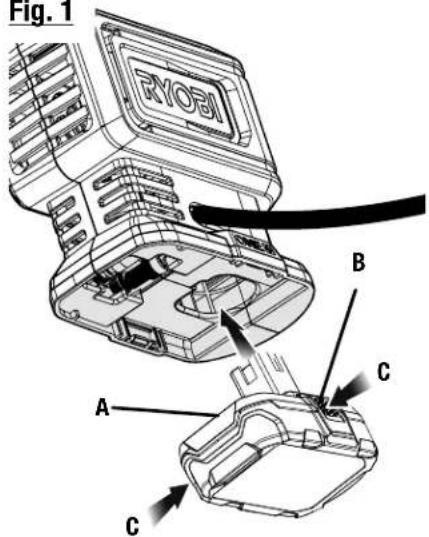
A - Battery pack (bloc-piles, paquete de baterías)
B - Latches (loquets, pestillos)
C - Depress latches to release battery pack (appuyer sur les loquets pour libérer le bloc-piles, para soltar el paquete de baterías, oprima los pestillos)
Fig. 2
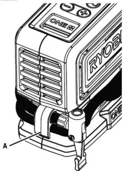
A - Hose storage area with clip (rangement du tuyau avec pince, almacenamiento de la manguera con el clip)
Fig. 3
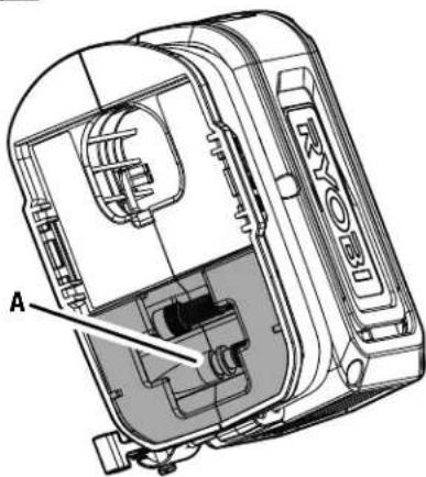
A - Accessory storage (rangement pour accessoires, almacenamiento de accesorios)
Fig. 4
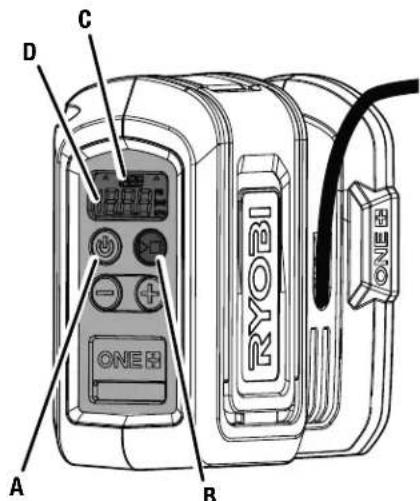
A - Power button (bouton de alimentation, botón de encendido)
B - Start/stop button (bouton de marche/arrêt, bouton de encendido/detención)
C - Programmed air pressure (pression d'air programmée, presión de aire programada)
D - Current air pressure (pression d'air actuelle, presión de aire actual)
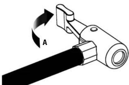
Fig. 5
natural_image
Mechanical component diagram showing a lever mechanism with rotation arrow and label A (no text or symbols beyond label)A - Air chuck clamp in unlocked position (attache du mandrin pneumatique en position déverrouillée, abrazadera del conector de inflado en posición desbloquear)
natural_image
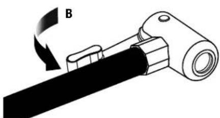
Mechanical assembly diagram showing a rotating tool with a curved arrow labeled B (no text or symbols present)B - Air chuck clamp in locked position (attache du mandrin pneumatique en position verrouillée, abrazadera del conector de inflado en posición trabada)
Fig. 6
A - Valve stem (tige de valve, vástago de válvula)
B - Air chuck (mandrin pneumatique, conector de inflado)
A - Tapered adaptor (adaptateur effilé, botón de adaptador cónico)
B - Presta valve adaptor (adaptateur de valve Presta, adaptador de válvula Presta)
C - Sport ball needle (aiguille arborer la balle, aguja para inflar pelotas deportivas)
D - Air chuck (mandrin pneumatique, conector de inflado)
Fig. 8
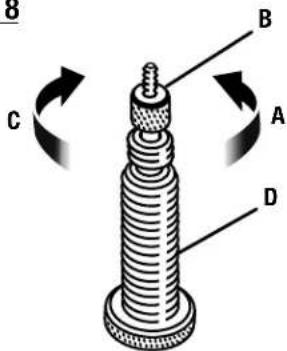
A - To loosen (pour desserrer, para aflojar)
B - Locking nut (écrou de blocage, contratuerca)
C - To tighten (pour serrer, para apretar)
D - Presta valve stem (tige de valve Presta, vástago de válvula Presta)
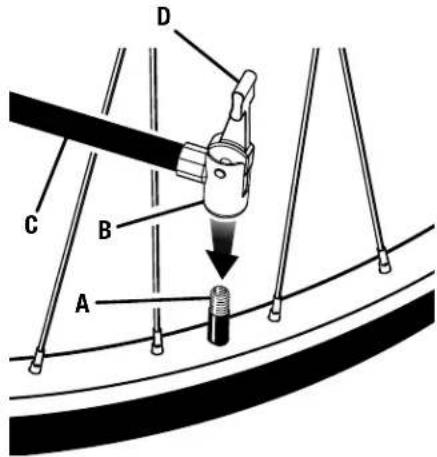
Fig. 9
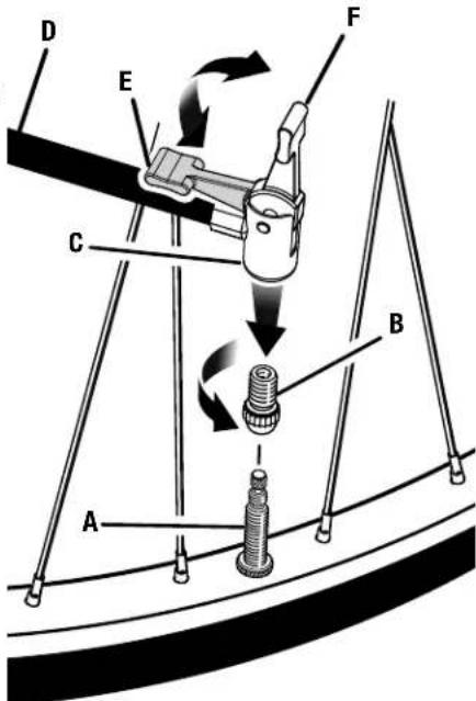
A - Presta valve (valve Presta, válvula Presta)
B - Presta valve adaptor (adaptateur de valve Presta, adaptador de válvula Presta)
C - Air chuck (mandrin pneumatique, conector de inflado)
D - Air hose (flexible pneumatique, manguera de aire)
E - Air chuck clamp in locked position (attache du mandrin pneumatique en position verrouillée, abrazadera del conector de inflado en posición trabada)
F - Air chuck clamp in unlocked position (attache du mandrin pneumatique en position déverrouillée, abrazadera del conector de inflado en posición desbloquear)
To request service, purchase replacement parts,
locate an Authorized Service Center or obtain Customer or Technical Support:
Visit www.ryobitools.com or call 1-800-525-2579
If any parts or accessories are damaged or missing, do not return this product to the store.
Call 1-800-525-2579 for immediate service.
Please obtain your model and serial number from the product data plate.
This product is covered under a 3-year limited Warranty. Proof of purchase is required.
MODEL NUMBER* ____ SERIAL NUMBER ____
*Model number on product may have additional letters at the end. These letters designate manufacturing information and should be provided when calling for service.
RYOBI is a trademark of Ryobi Limited and is used pursuant to a license granted by Ryobi Limited.