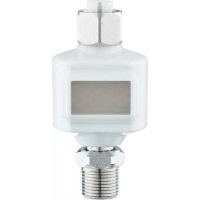
DP4200 - Industrial electronic display IFM - Free user manual and instructions
Find the device manual for free DP4200 IFM in PDF.


User questions about DP4200 IFM
0 question about this device. Answer the ones you know or ask your own.
Ask a new question about this device
Download the instructions for your Industrial electronic display in PDF format for free! Find your manual DP4200 - IFM and take your electronic device back in hand. On this page are published all the documents necessary for the use of your device. DP4200 by IFM.
USER MANUAL DP4200 IFM
Operating instructions
Analogue threshold display (IP 69K)
DP4200
Contents
1 Preliminary note 3
1.1 Symbols used 3
1.2 Warnings.... 3
1.3 Safety symbol on the device 3
2 Safety instructions.... 4
3 Intended use.... 5
3.1 Block diagram 5
4 Function 6
4.1 Use as a stand-alone device without IO-Link 6
4.2 Application as an IO-Link device 6
4.2.1 General information.... 6
4.2.2 Application example 7
4.2.3 Functionality 7
4.2.4 IO Device Description (IODD) 7
5 Installation.... 8
6 Electrical connection.... 9
6.1 Input side 9
6.2 Connecting the device.... 9
6.2.1 Mounting the connector.... 10
6.2.1.1 Maximum cable length 10
7 Operating and display elements 11
7.1 LEDs.... 11
7.2 Display 11
7.2.1 Representation of the measured current value 12
8 Menu.... 13
8.1 General.... 13
8.2 Parameters adjustable via IO-Link 13
8.2.1 SP1/rP1 — set point/reset point OUT1.... 13
8.2.2 FH1/FL1 — min/max switching limits for window function 13
8.2.3 A. Trm - analogue termination for OUT2.... 14
8.2.4 ou1 - output function for OUT1.... 14
8.2.5 dS1/dr1 — switching delay/switch-off delay for OUT1 14
8.2.6 ScAL — scaling of the displayed value.... 14
8.2.7 C. ASP/C. AEP - customer-specific analogue start/end point 15
8.2.8 coLr — display colours and colour changes.... 15
8.2.9 cFH/cFL — upper/lower value for colour change 16
8.2.10 diS — refresh rate of the displayed measured value 16
8.2.11 Lo/Hi - min/max measured input values 17
8.2.12 dAP-damping.... 17
8.2.13 C.uni - customer-specific unit 17
8.2.14 Application-specific tag 17
9 Operation 18
9.1 Functions output 1 18
9.2 Functions output 2 18
10 Troubleshooting 19
11 Maintenance, repair and disposal 20
1 Preliminary note
You will find instructions, technical data, approvals and further information using the QR code on the unit / packaging or at documentation.ifm.com.
1.1 Symbols used
√ Requirement
Instructions
Reaction, result
[...] Designation of keys, buttons or indications
→ Cross-reference

Important note
Non-compliance may result in malfunction or interference.

Information
Supplementary note
1.2 Warnings
Warnings indicate the possibility of personal injury and damage to property. This enables safe product handling. Warnings are graded as follows:

WARNING
Warning of serious personal injury
▷ If the warning is not observed, fatal and serious injuries are possible.

CAUTION
Warning of minor to moderate personal injury
▷ If the warning is not observed, minor to moderate injuries are possible.
ATTENTION
Warning of damage to property
▷ If the warning is not observed, damage to property is possible.
1.3 Safety symbol on the device

Safety symbol on the device:
▶ Adhere to the operating instructions for the safe operation of the unit.
2 Safety instructions
- The unit described is a subcomponent for integration into a system.
- The system architect is responsible for the safety of the system.
-
The system architect undertakes to perform a risk assessment and to create documentation in accordance with legal and normative requirements to be provided to the operator and user of the system. This documentation must contain all necessary information and safety instructions for the operator, the user and, if applicable, for any service personnel authorised by the architect of the system.
-
Read this document before setting up the product and keep it during the entire service life.
- The product must be suitable for the corresponding applications and environmental conditions without any restrictions.
- Only use the product for its intended purpose (→ Intended use).
- If the operating instructions or the technical data are not adhered to, personal injury and/or damage to property may occur.
- The manufacturer assumes no liability or warranty for any consequences caused by tampering with the product or incorrect use by the operator.
• Installation, electrical connection, set-up, programming, configuration, operation and maintenance of the product must be carried out by personnel qualified and authorised for the respective activity. - Protect units and cables against damage.
- Replace damaged units, otherwise the technical data and safety will be impaired.
- Observe applicable documents.
3 Intended use
The device is used for the evaluation of an analogue signal (4...20 mA) from a connected sensor or another device with analogue output (4...20 mA). The device has one analogue current input and two outputs: output 1 (digital) and optionally output 2 (analogue current output).
The device is suited for wet environments. Observe instructions in chapters "Installation" and "Electrical connection".
The unit is not suited for environments with particular requirements on mechanical stability (e.g. shock/vibration).
The unit is intended for indoor use only.
▶ Observe the operating conditions ( → Technical data at www.ifm.com).
3.1 Block diagram
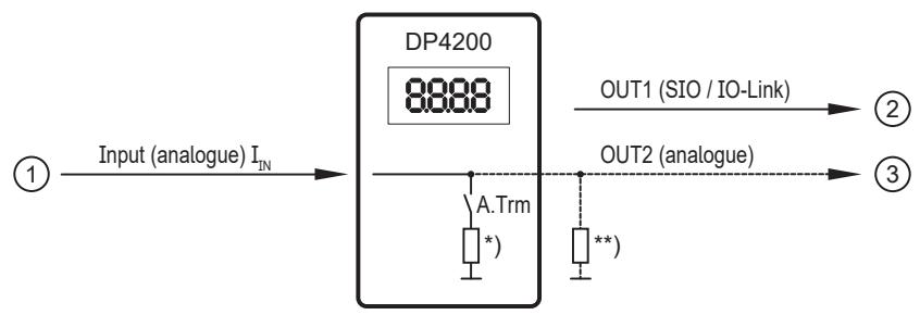
Fig. 1: Inputs/outputs of the device
1: IN (analogue input IIN )
2: OUT1 (digital output SIO / IO-Link)
3: OUT2 (analogue output IOUT = IIN )
A. Trm: analogue termination OUT2
*) switchable internal load
**) external load (optional)
Current rating: max. 50 mA for each output
The current loop of the analogue input must be terminated. Only one load may be connected, either an internal or an external load.
See:
A. Trm - analogue termination for OUT2 (→ 14)
Troubleshooting
4 Function
There are basically two modes in which the device can be operated:
• As stand-alone device
The device compares the measured current value with the set parameters and switches its output according to the selected parameters. This mode is without IO-Link functionality. The parameters can only be set with an IO-Link tool.
• As IO-Link device
The device operates as an "analogue/IO-Link converter". The evaluation of the measured current value depends on the parameters which are set with IO-Link tools or a PLC via IO-Link communication.
4.1 Use as a stand-alone device without IO-Link
The device compares the measured current value with the set parameters and switches its output according to the selected function ( → Operation).
The measured value is shown on the alphanumerical display. The displayed value can be scaled by the user (2-point scaling).
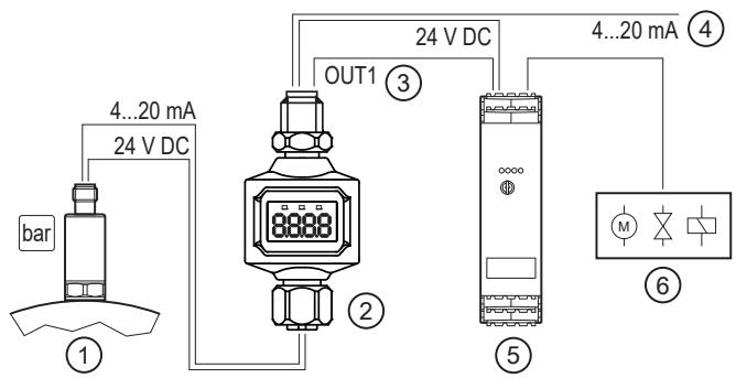
Fig. 2: Application example without IO-Link master
1: Sensor with analogue output (e.g. pressure sensor)
3: Digital output
5: Switching amplifiers
2: Threshold display
4: Looping through an analogue input signal
6: Relay output for switching of electric motors, valves etc.
4.2 Application as an IO-Link device
4.2.1 General information
The unit has an IO-Link communication interface which requires an IO-Link capable module (IO-Link master).
The IO-Link interface allows direct access to the process and diagnostic data and enables setting of the parameters of the unit during operation.
You will find further information about IO-Link and all the necessary information about the required IO-Link hardware and software at:
www.io-link.ifm
4.2.2 Application example

Fig. 3: Application example with IO-Link master
1: Sensor with analogue output (e.g. pressure sensor)
3: Fully bidirectional IO-Link communication
- Remote display: reading and displaying the measured current
- Remote parameter setting: reading and changing the parameter setting
5: IO-Link master
7: PLC
2: Threshold display
4: Looping through an analogue input signal
6: Fieldbus (e.g. Profibus, Profinet etc.)
4.2.3 Functionality
In the IO-Link SIO mode, the device has the same functionality as a stand-alone device. The measured value is also displayed.
Additionally, the device converts the measured current and transmits the value via IO-Link connection to the PLC.
4.2.4 IO Device Description (IODD)
You will find the IODDs required for configuration of the IO-Link device as well as detailed information about the process data structure, diagnostic information and parameter addresses at documentation.ifm.com
5 Installation
ATTENTION
Higher shock ≥ IK06
▷ Damage possible
▷ Protection rating and, in wet environments, electrical protection might be impaired
▶ If necessary, the system creator must take external measures to protect the device depending on the requirements of the corresponding application.
▶ Replace damaged devices, otherwise the technical data and safety will be impaired.
The IP rating of the overall system depends on the protection ratings of the individual devices, the applied connection elements and the corresponding protective caps.
ATTENTION
No protection rating / no protection of the contacts without mounted connectors / protective caps.
▷ Inadmissible soiling / moisture possible.
▷ Separation of circuits / safety might be impaired.
▷ Before installation / when replacing the device, observe pollution degree 2.
▶ Ensure separation / safety.
▶ Connect the M12 connectors of the device ( → Electrical connection).
▶ Install the device so that the M12 connection parts and the device are protected from mechanical stress such as shock and vibration.
▶ If necessary, fix the device with cable ties.

The following applies to all types of mounting:
The responsibility for the compliance with the requirements concerning mounting of the device in the application with regard to shock, vibration, acceleration and weight lies with the system architect.
6 Electrical connection

The unit must be connected by a qualified electrician.
Observe the national and international regulations for the installation of electrical equipment.
Voltage supply according to SELV, PELV.

CAUTION
Use in wet environments
▷ Electric shock possible.
▶ Voltage derating required ( → Technical data).
The circuit is insulated from device surfaces that could be touched with basic insulation according to IEC 61010-1 (secondary circuit with max. 32 V DC, supplied from the mains circuit up to 300 V of overvoltage category II).
The external wiring has to be carried out in a way that ensures the required separation from other circuits.

▶ External interference suppression of inductive loads is required.
6.1 Input side
Operating voltage (SELV/PELV)

CAUTION
The input current of the operating voltage is not limited.
▷ No fire protection.
▶ Protect the circuit.
▶ Protect the sensor supply via the same fuse.
| Potential | M12 connector 1 | Fuse |
| L+ / supply voltage | Pin 1 | ≤ 2 A |
Required tripping characteristic of the fuse:
Tfuse ≤ 120 s at max. 6.25 A (fire protection)
▶ Alternatively supply the device via a limited energy circuit according to IEC 61010-1 or class 2 according to UL1310.
6.2 Connecting the device
▶ Disconnect power.
▶ Connect the unit as follows:

Fig. 4: Electrical connection
1: 4-pole M12 connector
• Pin 1: L+ / supply voltage
• Pin 2: OUT2 (analogue output)
• Pin 3: L- / supply voltage
• Pin 4: OUT1 (digital output SIO / IO-Link)
2: 5-pole M12 socket
• Pin 1: L+ / sensor supply
• Pin 2: Analogue input (4...20 mA)
• Pin 3: L- / sensor supply
- Pin 4: not connected
- Pin 5: not connected

Always use the provided connection cables to connect other devices.

2-wire sensors can also be connected to the device.
See also application examples ( → Function)
6.2.1 Mounting the connector
The threaded connections in the device correspond to the M12 standard. To ensure compliance with the specified protection rating, only cables that comply with this standard may be used. In the case of self-assembled cables, the system manufacturer is responsible for the protection rating.
▶ Use connectors with gold-plated contacts.
▶ During installation, place the connectors vertically so that the coupling nut will not damage the thread.
▶ Observe the coding of the connectors during installation.
If connector in the device:
▶ Tighten the cable sockets according to the torque specifications indicated by the cable vendor. Maximum permissible tightening torque: 1.8 Nm
If sockets in the device:
▶ Tighten the cable plug using 1.3 ± 0.1 Nm.
▶ Provide all outgoing cables with suitable strain relief after a maximum of 200 mm. Observe the minimum bending radius of the cables ( → information from the cable manufacturer).
6.2.1.1 Maximum cable length
• Without IO-Link communication: 30 m on each side
• With IO-Link communication: 20 m on the master side
7 Operating and display elements

1: LED I
2: LED Power
3: LED II
4: Display
7.1 LEDs
| LED | Colour | Status | Designation | |
| I | OUT1 | yellow | on | Output 1 switched. |
| Power | green | on | Voltage supply OK. Device in operating mode. | |
| off | No voltage supply. Device switched off. | |||
| II | OUT2 | yellow | on | Output 2 switched. |
Error signals and diagnostics: → Troubleshooting
7.2 Display
| Colour | Designation |
| Red/green | 7-segment LED display, 4 digits, with colour change |
Error signals and diagnostics: → Troubleshooting
In the operating mode the input current value is displayed. The scaling depends on the parameter ScAL — scaling of the displayed value ( → ☐ 14).
7.2.1 Representation of the measured current value
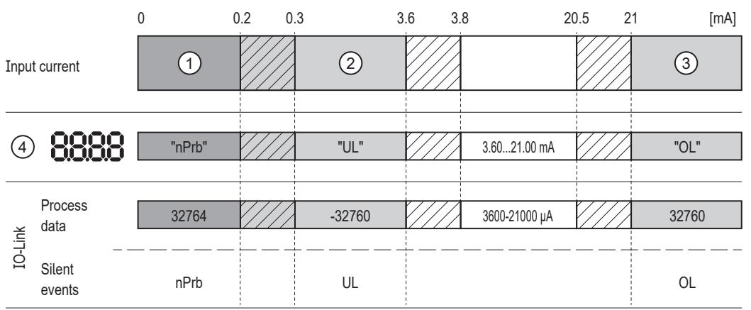
1: No measured data
2: Input current below the range (-)
3: Input current above the range (+)
4: Displayed message or value.
The input current is not displayed scaled here.
nPrb: No sensor
UL: Process value too low
OL: Process value too high
Hysteresis range
8 Menu
8.1 General
Irrespective of the operating mode (standard IO mode or IO-Link device), the device can be configured via an IO-Link tool.

Parameter cloning and parameter setting backup is possible with an IO-Link tool.
The scaling parameter [ScAL] only influences the display and not the transferred process data or the actual switching threshold values.
Via IO-Link, the current value is always transmitted in µA → Representation of the measured current value ( → ☐ 12). The switching thresholds can be set in steps of 0.01 mA.
8.2 Parameters adjustable via IO-Link
The following functions or parameters are only available via IO-Link tools.
8.2.1 SP1/rP1 — set point/reset point OUT1
Upper/lower limit for measuring current at which OUT1 switches with hysteresis setting. Only displayed if the hysteresis function [Hno] or [Hnc] is set in [ou1].
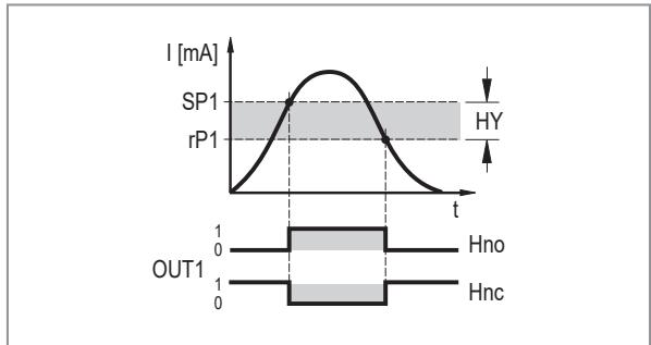
Fig. 5: Hysteresis functions
SP: Switch point
rP: Reset point
HY: Hysteresis
Hno: Hysteresis function normally open
Hnc: Hysteresis function normally closed
▶ Select [SP1] and set the value at which output OUT1 switches.
▶ Select [rP1] and set the value at which output OUT1 switches off.

[rP1] is always smaller than [SP1]. The device only accepts values which are lower than the value for [SP1].

[rP1] follows the changes of [SP1] and keeps the set hysteresis.
8.2.2 FH1/FL1 — min/max switching limits for window function
Upper/lower limit for measuring current at which OUT1 switches within the window setting. The parameters are only displayed if the window function [Fno] or [Fnc] is set in [ou1].
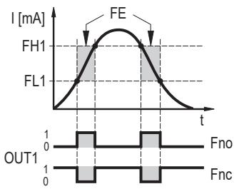
Fig. 6: Window functions
▶ Select [FH1] and set the upper limit.
▶ Select [FL1] and set the lower limit.
[FL1] is always smaller than [FH1]. The device only accepts values which are lower than the value for [FH1].
[FL1] follows the changes of [FH1] and keeps the set hysteresis.
8.2.3 A. Trm – analogue termination for OUT2
• [OFF] = OUT2 is externally connected, e.g. to the analogue input of another device.
- [On] = OUT2 is not connected and the current path is terminated internally.
Note the following for proper current measurement and evaluation: If the internal analogue termination is set to [On], output OUT2 must not be connected.
8.2.4 ou1 — output function for OUT1
Switching signal for the current limits.
• [Hno] = hysteresis function / normally open
• [Hnc] = hysteresis function / normally closed
• [Fno] = window function / normally open
• [Fnc] = window function / normally closed
See also:
SP1/rP1 — set point/reset point OUT1 ( → ☐ 13)
FH1/FL1 — min/max switching limits for window function ( → ☐ 13)
8.2.5 dS1/dr1 — switching delay/switch-off delay for OUT1
Value: 0.0...50.0 s (0.0 = delay time is not active)
8.2.6 ScAL — scaling of the displayed value
The setting defines the position of the decimal point of the displayed value and acts like a multiplier for the parameters [C. ASP]/[C. AEP].
• [OFF] = measured current value is not scaled.
• [cccc] = scaling without decimal place (x 0001).
• [ccc.c] = scaling with 1 decimal place (x 000.1).
• [cc.cc] = scaling with 2 decimal places (x 00.01).
• [c.ccc] = scaling with 3 decimal places (x 0.001).
8.2.7 C. ASP/C. AEP - customer-specific analogue start/end point
Settings for scaled display values.
The parameters are only displayed if [ScAL] is set to [cccc], [ccc.c], [cc.cc] or [c.ccc].
C. ASP value: -746 ... 9745 corresponds to 4 mA.
C. AEP value: -366 ... 9366 corresponds to 20 mA.

If a scaling is set via [ScAL] with parameter setting being done via IO-Link, the C. ASP value and the C. AEP value also have to be selected accordingly:
With [ScAL] = [ccc.c] → C. ASP and C. AEP value x 10
With [ScAL] = [cc.cc] → C. ASP and C. AEP value x 100
With [ScAL] = [c.ccc] → C. ASP and C. AEP value x 1000
With parameter setting being done on the device, the decimal place is displayed. The required values can be selected without having to be converted.

All displayed current values are interpolated based on a 2-point approximation ([SP1]+[rP1], [FH1]+[FL1], [cFH]+[cFL], [Lo]+[Hi]).
IO-Link process data and parameters are not affected by the scaling.

C. ASP = min. value
C. AEP = max. value

C. ASP = max. value
C. AEP = min. value
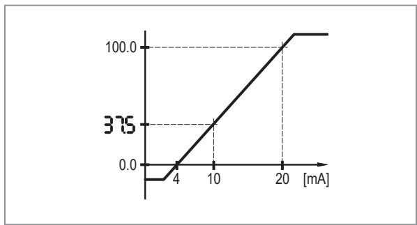
Fig. 7: Example with scaled display value
| Menu setting | IO-Link parameter setting | |
| ScAL | ccc.c | ccc.c |
| C. ASP | 0.0 | 0 |
| C. AEP | 100.0 | 1000 |
| Input | 10 mA | 10 mA |
| Indication | 37.5 | 37.5 |
8.2.8 coLr — display colours and colour changes
Assignment of the display colours "red" and "green" within the measuring range.
• [rEd] = continuously red (independent of the measured value).
- [GrEn] = continuously green (independent of the measured value).
• [r1ou] = red when OUT1 switches.
• [G1ou] = green when OUT1 switches.
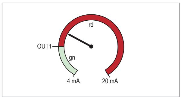
Fig. 8: Hysteresis function with [r1ou]

Fig. 9: Hysteresis function with [G1ou]

Fig. 10: Window function with [r1ou]
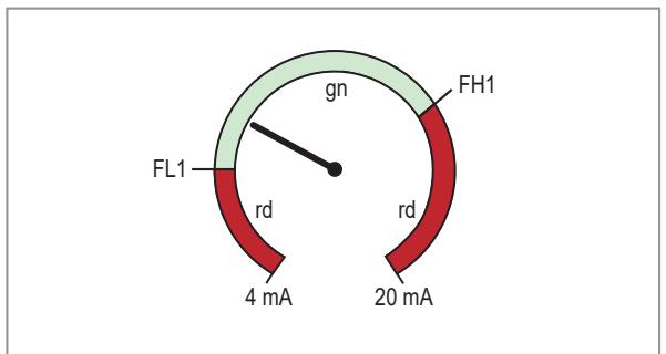
Fig. 11: Window function with [G1ou]
[r-cF] = red when the measured value is between the values [cFL] and [cFH].
[G-cF] = green when the measured value is between the values [cFL] and [cFH].
8.2.9 cFH/cFL — upper/lower value for colour change
When setting [coLr] to [r-cF] or [G-cF]:
▶ Select [cFH] and set the upper limit.
Setting range corresponds to the measured values. The lowest setting value is [cFL].
▶ Select [cFL] and set the lower limit value.
Setting range corresponds to the measured values. The highest setting value is [cFH].
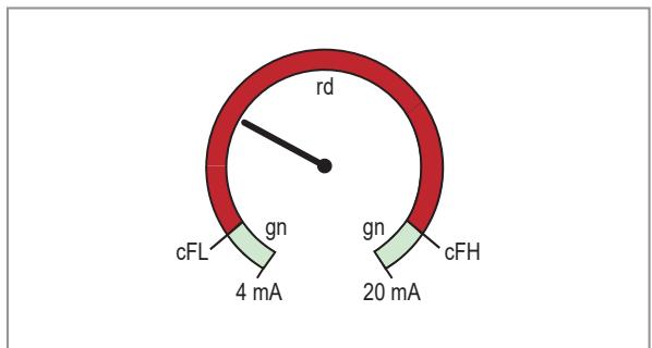
Fig. 12: Function [r-cF]

Fig. 13: Function [G-cF]
For b/w printouts: gn = green, rd = red
8.2.10 diS — refresh rate of the displayed measured value
• [OFF][ = The measured value display is deactivated in the operating mode.]
• [d1] = update of the measured values every 50 ms.
• [d2] = update of the measured values every 200 ms.
• [d3] = update of the measured values every 600 ms.

Even with an unsteady input value, [d1] provides optimum readability.
8.2.11 Lo/Hi — min/max measured input values
[Lo] = lowest measured value
[Hi] = highest measured value
8.2.12 dAP — damping
Damping of the measured analogue value.
Setting also influences the set point, the IO-Link process data and the display.
Value: 0.000...4.000 s (T value: 63 %).
At 0.000 damping is not active.
8.2.13 C.uni – customer-specific unit
Customer-specific unit with max. 4 characters.
8.2.14 Application-specific tag
Customer-specific application description, max. 32 characters long.
Default value: “ *** ” / can be freely defined by the customer
9 Operation
After power on, the device is in the operating mode (SIO). It carries out its measurement and evaluation functions and provides output signals according to the set parameters.
9.1 Functions output 1
OUT1 (connector, pin 4):
• Digital output (SIO)
- IO-Link interface
Selectable switching functions:
- Hysteresis functions, normally open / normally closed: SP1/rP1 — set point/reset point OUT1 (→ 13)
- Window functions, normally open / normally closed: FH1/FL1 — min/max switching limits for window function ( → ☐ 13)
OUT1 changes its status if the input signal is above or below the set switching limits. First the switch point SP1 is set, then the reset point rP1: SP1/rP1 — set point/reset point OUT1 ( → ☐ 13).

The hysteresis defined remains even if [SP1] is changed again. Changing the parameter [rP1] also changes the hysteresis.
The width of the window can be set by means of the difference between FH1 and FL1.
FH1 = upper value
FL1 = lower value
9.2 Functions output 2
OUT2 (connector, pin 2):
- Analogue output (looping through the analogue input signal)
10 Troubleshooting
| Display | LED | Error | Troubleshooting | ||
| I | Power | II | |||
| OFF | off | off | off | Supply voltage too low. | Check/correct the supply voltage: Electrical connection |
| SC1 | flashes | can differ | can differ | Excessive current at switching output OUT1. | Check switching output OUT1 for short circuit or excessive current. Remove the fault. |
| OL | can differ | on | can differ | Process value too high (measured current >21 mA). | Check connected sensor and current range: Representation of the measured current value (→ 12) Check the setting for internal or external analogue termination for OUT2: A. Trm - analogue termination for OUT2 (→ 14) |
| UL | can differ | on | can differ | Process value too low (measured current < 3.6 mA). | |
| nPrb | can differ | on | can differ | No sensor connected to the analogue input. | |
11 Maintenance, repair and disposal
The unit is maintenance-free.
▶ Carry out cleaning considering the technical data (protection rating) and the connection technology used.
▶ Cleaning agents must be checked by the system manufacturer / operator for their suitability for the device materials ( → Technical data) and the connection technology used.
▶ The cleaning agents must not damage the device materials.
▶ It is not possible to repair the unit.
▶ After use, dispose of the unit in an environmentally friendly way in accordance with the applicable national regulations.
- 1 PRELIMINARY NOTE
- 1.1 SYMBOLS USED
- 1.2 WARNINGS
- 1.3 SAFETY SYMBOL ON THE DEVICE
- 2 SAFETY INSTRUCTIONS
- 3 INTENDED USE
- 3.1 BLOCK DIAGRAM
- 4 FUNCTION
- 4.1 USE AS A STAND-ALONE DEVICE WITHOUT IO-LINK
- 4.2 APPLICATION AS AN IO-LINK DEVICE
- 4.2.1 GENERAL INFORMATION
- 4.2.2 APPLICATION EXAMPLE
- 4.2.3 FUNCTIONALITY
- 4.2.4 IO DEVICE DESCRIPTION (IODD)
- 5 INSTALLATION
- 6 ELECTRICAL CONNECTION
- 6.1 INPUT SIDE
- 6.2 CONNECTING THE DEVICE
- 6.2.1 MOUNTING THE CONNECTOR
- 6.2.1.1 MAXIMUM CABLE LENGTH
- 7 OPERATING AND DISPLAY ELEMENTS
- 7.1 LEDS
- 7.2 DISPLAY
- 7.2.1 REPRESENTATION OF THE MEASURED CURRENT VALUE
- 8 MENU
- 8.1 GENERAL
- 8.2 PARAMETERS ADJUSTABLE VIA IO-LINK
- 8.2.1 SP1/RP1 — SET POINT/RESET POINT OUT1
- 8.2.2 FH1/FL1 — MIN/MAX SWITCHING LIMITS FOR WINDOW FUNCTION
- 8.2.3 A. TRM – ANALOGUE TERMINATION FOR OUT2
- 8.2.4 OU1 — OUTPUT FUNCTION FOR OUT1
- 8.2.5 DS1/DR1 — SWITCHING DELAY/SWITCH-OFF DELAY FOR OUT1
- 8.2.6 SCAL — SCALING OF THE DISPLAYED VALUE
- 8.2.7 C. ASP/C. AEP - CUSTOMER-SPECIFIC ANALOGUE START/END POINT
- 8.2.8 COLR — DISPLAY COLOURS AND COLOUR CHANGES
- 8.2.9 CFH/CFL — UPPER/LOWER VALUE FOR COLOUR CHANGE
- 8.2.10 DIS — REFRESH RATE OF THE DISPLAYED MEASURED VALUE
- 8.2.11 LO/HI — MIN/MAX MEASURED INPUT VALUES
- 8.2.12 DAP — DAMPING
- 8.2.13 C.UNI – CUSTOMER-SPECIFIC UNIT
- 8.2.14 APPLICATION-SPECIFIC TAG
- 9 OPERATION
- 9.1 FUNCTIONS OUTPUT 1
- 9.2 FUNCTIONS OUTPUT 2
- 10 TROUBLESHOOTING
- 11 MAINTENANCE, REPAIR AND DISPOSAL
Brand : IFM
Model : DP4200
Category : Industrial electronic display