USER MANUAL Estate 7102 HWSY STIGA
Thank you for purchasing a Honda engine! We want to help you to get the best results from your new engine and to operate it safely. This manual contains information on how to do that; please read it carefully before operating the engine. If a problem should arise, or if you have any questions about your engine, consult an authorized Honda servicing dealer.
All information in this publication is based on the latest product information available at the time of printing. Honda Motor Co., Ltd. reserves the right to make changes at any time without notice and without incurring any obligation. No part of this publication may be reproduced without written permission.
This manual should be considered a permanent part of the engine and should remain with the engine if resold.
Review the instructions provided with the equipment powered by this engine for any additional information regarding engine startup, shutdown, operation, adjustments or any special maintenance instructions.
United States, Puerto Rico, and U.S. Virgin Islands:
We suggest you read the warranty policy to fully understand its coverage and your responsibilities of ownership. The warranty policy is a separate document that should have been given to you by your dealer.
SAFETY MESSAGES
Your safety and the safety of others are very important. We have provided important safety messages in this manual and on the engine. Please read these messages carefully.
A safety message alerts you to potential hazards that could hurt you or others. Each safety message is preceded by a safety alert symbol and one of three words, DANGER, WARNING, or CAUTION.
These signal words mean:
DANGER
You WILL be KILLED or SERIOUSLY HURT if you don't follow instructions.
WARNING
You CAN be KILLED or SERIOUSLY HURT if you don't follow instructions.
CAUTION
You CAN be HURT if you don't follow instructions.
Each message tells you what the hazard is, what can happen, and what you can do to avoid or reduce injury.
DAMAGE PREVENTION MESSAGES
You will also see other important messages that are preceded by the word NOTICE.
This word means:
NOTICE
Your engine, other property, or the environment can be damaged if you don't follow instructions.
This entire book is filled with important safety information – please read it carefully.
©2019 Honda Motor Co., Ltd. –All Rights Reserved
GXV630R-GXV690R
37ZCS603
00X37-ZCS-6030
HONDA
OWNER'S MANUAL MANUEL DE L'UTILISATEUR MANUAL DEL PROPIETARIO
GXV630·GXV690
natural_image
Technical line drawing of a mechanical component with no visible text or symbols

WARNING:

The engine exhaust from this product contains chemicals known to the State of California to cause cancer, birth defects or other reproductive harm.
CONTENTS
INTRODUCTION....1
SAFETY MESSAGES....1
SAFETY INFORMATION......2
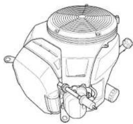
SAFETY LABEL LOCATION ......2
COMPONENT & CONTROL
LOCATION....3
FEATURES....3
BEFORE OPERATION CHECKS......4
OPERATION......4
SAFE OPERATING
PRECAUTIONS....4
STARTING THE ENGINE ....4
STOPPING THE ENGINE....5
SETTING ENGINE SPEED....5
SERVICING YOUR ENGINE....6
THE IMPORTANCE OF
MAINTENANCE 6
SAFETY PRECAUTIONS......6
MAINTENANCE
SCHEDULE 6
REFUELING 7
ENGINE OIL....7
Recommended Oil....7
Oil Level Check....7
Oil Change....8
OIL FILTER....8
AIR CLEANER....9
Inspection....9
Cleaning....9
SPARK PLUG 10
HELPFUL TIPS & SUGGESTIONS ...10
STORING YOUR ENGINE .....10
TRANSPORTING....12
TAKING CARE OF UNEXPECTED
PROBLEMS....12
TECHNICAL INFORMATION .....13
Serial Number Location .....13
Battery Connections for
Electric Starter 13
Remote Control Linkage.....14
Carburetor Modifications for
High Altitude Operation.....14
Emission Control System
Information....15
Air Index....16
Specifications....16
Tuneup Specifications.....17
Quick Reference Information...17
Wiring Diagrams.....17
CONSUMER INFORMATION.....18
WARRANTY AND
DISTRIBUTOR/DEALER
LOCATOR INFORMATION .....18
CUSTOMER SERVICE
INFORMATION....18
- Understand the operation of all controls and learn how to stop the engine quickly in case of emergency. Make sure the operator receives adequate instruction before operating the equipment.
- Do not allow children to operate the engine. Keep children and pets away from the area of operation.
- Your engine's exhaust contains poisonous carbon monoxide. Do not run the engine without adequate ventilation, and never run the engine indoors.
• The engine and exhaust become very hot during operation. Keep the engine at least 1 meter (3 feet) away from buildings and other equipment during operation. Keep flammable materials away, and do not place anything on the engine while it is running.
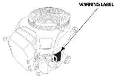
This label warns you of potential hazards that can cause serious injury. Read it carefully.
If the label comes off or becomes hard to read, contact your servicing dealer for replacement.
| WARNING LABEL For EU Except EU | |
| attached to product | supplied with product |
| ⚠ WARNINGGasoline is highly flammable and explosive.Turn engine off and let cool before refueling.The engine emits toxic carbon monoxide.Do not run in an enclosed area.Read Owner's Manual before operation. | supplied with product | attached to product |
| ⚠ ATTENTIONL'essence est très inflammable et explosive.Amitter le moteur et la laser refrideur avant de faire le plein d'essence.La moteur produit les vapeurs nocives de monocyte de carbone.Ne pas utiliser dans un local enclos.Line le manuel de propriétaire avant l'utilisation. | supplied with product | supplied with product |
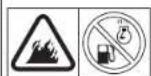
Gasoline is highly flammable and explosive. Stop the engine and let cool before refueling.
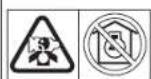
The engine emits toxic poisonous carbon monoxide gas. Do not run in an enclosed area.
Read Owner's Manual before operation.


The engine is equipped with a fuel-cut solenoid that allows fuel to flow to the carburetor main jet when the engine switch is in the ON or START position and stops the flow of fuel to the main jet when the engine switch is in the OFF position.
The engine must be connected to the battery to energize the fuel-cut solenoid, allowing the engine to run. If the battery is disconnected, fuel flow to the carburetor will stop.

For your safety, and to maximize the service life of your equipment, it is very important to take a few moments before you operate the engine to check its condition. Be sure to take care of any problem you find, or have your servicing dealer correct it, before you operate the engine.
WARNING
Failure to properly maintain this engine, or failing to correct a problem before operation, could result in a significant malfunction.
Some malfunctions can cause serious injuries or death.
Always perform a pre-operation inspection before each operation and correct any problems.
Before beginning your pre-operation checks, be sure the engine is level and the engine switch is in the OFF position.
Always check the following items before you start the engine:
Check the General Condition of the Engine
- Before each use, look around and underneath the engine for signs of oil or gasoline leaks.
- Remove any excessive dirt or debris, especially around the muffler.
- Remove any objects or debris that may block the cooling air intake at the screen grid cover. Running the engine with a blocked air intake can cause engine damage.
- Look for signs of damage.
- Check that all shields and covers are in place, and all nuts, bolts, and screws are tightened.
Check the Engine
- Check the fuel level. Starting with a full tank will help to eliminate or reduce operating interruptions for refueling.
- Check the engine oil level (see page 7). Running the engine with a low oil level can cause engine damage.
- Check the air filter element (see page 9). A dirty air filter element will restrict air flow to the carburetor, reducing engine performance.
- Check the equipment powered by this engine.
Review the instructions provided with the equipment powered by this engine for any precautions and procedures that should be followed before engine startup.
OPERATION
SAFE OPERATING PRECAUTIONS
Before operating the engine for the first time, please review the SAFETY INFORMATION section on page 2 and the BEFORE OPERATION CHECKS on page 4.
Carbon Monoxide Hazards
For your safety, do not operate the engine in an enclosed area such as a garage. Your engine's exhaust contains poisonous carbon monoxide gas that can collect rapidly in an enclosed area and cause illness or death.
WARNING
Exhaust contains poisonous carbon monoxide gas that can build up to dangerous levels in closed areas.
Breathing carbon monoxide can cause unconsciousness or death.
Never run the engine in a closed, or even partly closed area.
Review the instructions provided with the equipment powered by this engine for any safety precautions that should be observed with engine startup, shutdown, or operation.
Do not operate the engine on slopes greater than 20° (36%).
STARTING THE ENGINE
- If the fuel tank is equipped with a valve, be sure the fuel valve is in the OPEN or ON position before attempting to start the engine.
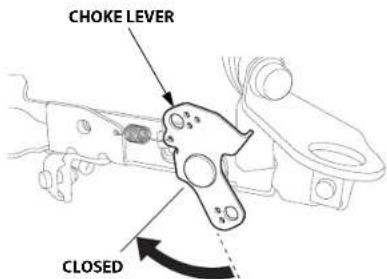
- To start a cold engine, move the choke lever to the CLOSED position.
To restart a warm engine, leave the choke lever in the OPEN position.
Some engine applications use a remote-mounted choke control rather than the engine-mounted choke lever shown here. Refer to the instructions provided with the equipment powered by this engine for remote control information.
OPEN
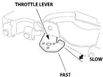
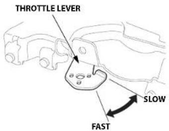
- Move the throttle lever away from the SLOW position, about 1/3 of the way toward the FAST position.
Some engine applications use a remote-mounted throttle control rather than the engine-mounted throttle lever shown here. Refer to the instructions provided with the equipment powered by this engine for remote control information.
-
Turn the engine switch to the ON position.
-
Operate the starter.
Turn the engine switch to the START position, and hold it there until the engine starts.
If the engine fails to start within 5 seconds, release the engine switch, and wait at least 10 seconds before operating the starter again.
NOTICE
Using the electric starter for more than 5 seconds at a time will overheat the starter motor and can damage it.
When the engine starts, release the engine switch, allowing it to return to the ON position.
-
Warm up the engine for 2 or 3 minutes.
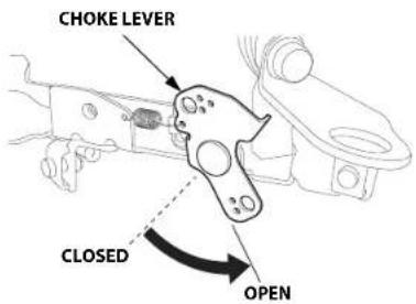
-
If the choke lever was moved to the CLOSED position to start the engine, gradually move it to the OPEN position as the engine warms up.
STOPPING THE ENGINE
To stop the engine in an emergency, simply turn the engine switch to the OFF position. Under normal conditions, use the following procedure. Refer to the instructions provided by the equipment manufacturer.
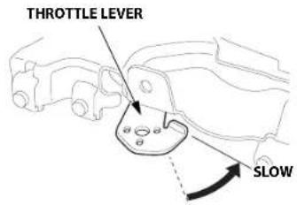
- Move the throttle lever to the SLOW position.
Some engine applications use a remote-mounted throttle control rather than the engine-mounted throttle lever shown here. Refer to the instructions provided with the equipment powered by this engine for remote control information.
-
Turn the engine switch to the OFF position.
-
If the fuel tank is equipped with a valve, turn the fuel valve to the CLOSED or OFF position.
SETTING ENGINE SPEED
Position the throttle lever for the desired engine speed.
Some engine applications use a remote-mounted throttle control rather than the engine-mounted throttle lever shown here. Refer to the instructions provided by the equipment manufacturer.
For engine speed recommendations, refer to the instructions provided with the equipment powered by this engine.
Do not disconnect the battery from the engine while the engine is running. Disconnecting the battery causes the fuel-cut solenoid to shut off the flow of fuel to the carburetor main jet, and the engine will stop.
SERVICING YOUR ENGINE
THE IMPORTANCE OF MAINTENANCE
Good maintenance is essential for safe, economical, and trouble-free operation. It will also help reduce pollution.
WARNING
Failure to properly maintain this engine, or failing to correct a problem before operation, could result in a significant malfunction.
Some malfunctions can cause serious injuries or death.
Always follow the inspection and maintenance recommendations and schedules in this owner's manual.
To help you properly care for your engine, the following pages include a maintenance schedule, routine inspection procedures, and simple maintenance procedures using basic hand tools. Other service tasks that are more difficult, or require special tools, are best handled by professionals and are normally performed by a Honda technician or other qualified mechanic.
The maintenance schedule applies to normal operating conditions. If you operate your engine under severe conditions, such as sustained high-load or high-temperature operation, or use in unusually wet or dusty conditions, consult your servicing dealer for recommendations applicable to your individual needs and use.
Maintenance, replacement, or repair of the emission control devices and systems may be performed by any engine repair establishment or individual, using parts that are "certified" to EPA standards.
MAINTENANCE SAFETY
Some of the most important safety precautions follow. However, we cannot warn you of every conceivable hazard that can arise in performing maintenance. Only you can decide whether or not you should perform a given task.
WARNING
Improper maintenance can cause an unsafe condition.
Failure to properly follow maintenance instructions and precautions can cause serious injuries or death.
Always follow the procedures and precautions in this owner's manual.
SAFETY PRECAUTIONS
• Make sure the engine is off before you begin any maintenance or repairs. To prevent accidental startup, disconnect the spark plug cap. This will eliminate several potential hazards:
- Carbon monoxide poisoning from engine exhaust.
Operate outside, away from open windows or doors.
- Burns from hot parts.
Let the engine and exhaust system cool before touching.
- Injury from moving parts.
Do not run the engine unless instructed to do so.
- Read the instructions before you begin, and make sure you have the tools and skills required.
- To reduce the possibility of fire or explosion, be careful when working around gasoline. Use only a non-flammable solvent, not gasoline, to clean parts. Keep cigarettes, sparks and flames away from all fuel related parts.
Remember that an authorized Honda servicing dealer knows your engine best and is fully equipped to maintain and repair it.
To ensure the best quality and reliability, use only new Honda Genuine parts or their equivalents for repair and replacement.
MAINTENANCE SCHEDULE
| REGULAR SERVICE PERIOD (3)Perform at everyindicated month oroperating hour interval,whichever comes first. | Each Use | First Monthor20 Hrs | Every 6Monthsor100 Hrs | Every Yearor300 Hrs | Every 2Yearsor500 Hrs | Refer to Page |
| ITEM |
| Engine oil Check level o 7 | | | | | | |
| Change o o 8 | | | | | |
| Engine oil filter Replace Every 200 Hrs. | 8 | |
| Air cleaner | Check | o 9 | | | | | |
| Clean | | | o (1) | | | 9 |
| Replace | | | | | D^* |
| Spark plug | Check-adjust | | | o | | | 10 |
| Replace | | | | o | |
| Idle speed | Check-adjust | | | | o (2) | | ** |
| Valve clearance | Check-adjust | | | | o (2) | | ** |
| Combustion chamber | Clean | After every 1000 Hrs. (2) | ** |
| Fuel filter | Replace | | | | o (2) | | ** |
| Fuel tube | Check | Every 2 years(Replace if necessary) (2) | ** |
* Replace the paper filter element only.
** Refer to the Shop Manual.
(1) Service more frequently when used in dusty areas.
(2) These items should be serviced by your servicing dealer, unless you have the proper tools and are mechanically proficient. Refer to the Honda shop manual for service procedures.
(3) For commercial use, log hours of operation to determine proper maintenance intervals.
Failure to follow this maintenance schedule could result in non-warrantable failures.
REFUELING
Recommended Fuel
| Unleaded gasoline |
| U.S. Pump octane rating 86 or higher |
| Except U.S. Research octane rating 91 or higher |
|
|
This engine is certified to operate on unleaded gasoline with a pump octane rating of 86 or higher (a research octane rating of 91 or higher). Refuel in a well ventilated area with the engine stopped. If the engine has been running, allow it to cool first. Never refuel the engine inside a building where gasoline fumes may reach flames or sparks.
You may use unleaded gasoline containing no more than 10% ethanol (E10) or 5% methanol by volume. In addition, methanol must contain cosolvents and corrosion inhibitors. Use of fuels with content of ethanol or methanol greater than shown above may cause starting and/or performance problems. It may also damage metal, rubber, and plastic parts of the fuel system. Engine damage or performance problems that result from using a fuel with percentages of ethanol or methanol greater than shown above are not covered under the Warranty.
If your equipment will be used on an infrequent or intermittent basis, please refer to the fuel section of the STORING YOUR ENGINE chapter (see page 10) for additional information regarding fuel deterioration.
WARNING
Gasoline is highly flammable and explosive.
You can be burned or seriously injured when handling fuel.
- Stop the engine and let it cool before handling fuel.
- Keep heat, sparks, and flame away.
- Handle fuel only outdoors.
- Keep away from your vehicle.
• Wipe up spills immediately.
NOTICE
Fuel can damage paint and some types of plastic. Be careful not to spill fuel when filling your fuel tank. Damage caused by spilled fuel is not covered under the Distributor's Limited Warranty.
Never use gasoline that is stale, contaminated, or mixed with oil. Avoid getting dirt or water in the fuel tank.
With the engine stopped and on a level surface, remove the fuel filler cap and check the fuel level. Refill the tank if the fuel level is low.
Refer to the instructions provided with the equipment powered by this engine for refuelling.
Refuel in a well-ventilated area before starting the engine. If the engine has been running, allow it to cool. Refuel carefully to avoid spilling fuel. It may be necessary to lower the fuel level depending on operating conditions. After refueling, tighten the fuel tank cap securely.
Keep gasoline away from appliance pilot lights, barbecues, electric appliances, power tools, etc.
Spilled fuel is not only a fire hazard, it causes environmental damage. Wipe up spills immediately.
ENGINE OIL
Oil is a major factor affecting performance and service life. Use 4-stroke automotive detergent oil.
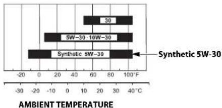
Recommended Oil
Use 4-stroke motor oil that meets or exceeds the requirements for API service category SJ or later (or equivalent). Always check the API service label on the oil container to be sure it includes the letters SJ or later (or equivalent).
bar
| Material | Ambient Temperature (°C) |
|---|---|
| 30 | 40 |
| 5W-30-10W-30 | 60 |
| Synthetic 5W-30 | 80 |
SAE 10W-30 or 5W-30 is recommended for general use. Use a full synthetic 5W-30 for starting/operating temperatures between 5°F (-15°C) and -13°F (-25°C). Other viscosities shown in the chart may be used when the average temperature in your area is within the indicated range.
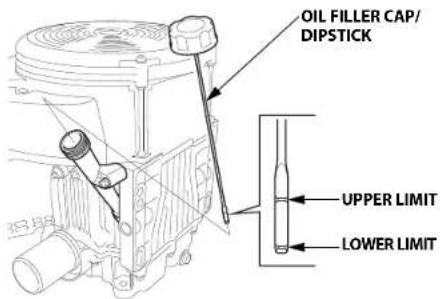
Oil Level Check
Check the engine oil level with the engine stopped and in a level position.
- Start the engine and let it idle for 1 or 2 minutes. Stop the engine and wait for 2 or 3 minutes.
- Remove the oil filler cap/dipstick and wipe it clean.
- Insert and remove the oil filler cap/dipstick without screwing it into the oil filler neck, then remove it to check the oil level shown on the dipstick.
-
If the oil level is near or below the lower limit mark on the dipstick, fill with the recommended oil to the upper limit mark.
-
Reinstall the oil filler cap/dipstick.
NOTICE
Running the engine with a low oil level can cause engine damage. This type of damage is not covered by the Distributor's Limited Warranty.
Drain the used oil when the engine is warm. Warm oil drains quickly and completely.
-
Place a suitable container below the engine to catch the used oil, then remove the oil filler cap/dipstick, drain bolt and sealing washer.
-
Allow the used oil to drain completely, then reinstall the drain bolt and new sealing washer, and tighten the drain bolt securely.
TORQUE: 45.0 N·m (4.5 kgf·m, 33 lbf·ft)
Please dispose of used motor oil in a manner that is compatible with the environment. We suggest you take used oil in a sealed container to your local recycling center or service station for reclamation. Do not throw it in the trash, pour it on the ground, or pour it down a drain.
- With the engine in a level position, fill with the recommended oil to the upper limit mark on the dipstick.
Engine oil capacity:
Without oil filter replacement: 1.7 L (1.8 US qt, 1.5 Imp qt)
With oil filter replacement: 1.9 L (2.0 US qt, 1.7 Imp qt)

NOTICE
Running the engine with a low oil level can cause engine damage. This type of damage is not covered by the Distributor's Limited Warranty.
- Reinstall the oil filler cap/dipstick securely.
OIL FILTER
Change
-
Drain the engine oil, and retighten the drain bolt securely.
-
Remove the oil filter with an oil filter socket tool and drain the remaining oil into a suitable container. Dispose the used oil and filter in a manner compatible with the environment.
NOTICE
Use an oil filter socket, rather than a strap wrench, to avoid striking and damaging the oil filter.
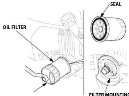
FILTER MOUNTING BASEOIL FILT
- Clean the filter mounting base, and coat the seal of the new oil filter with clean engine oil.
NOTICE
Use only a Honda Genuine oil filter or a filter of equivalent quality specified for your model. Using the wrong filter, or a non-Honda filter which is not of equivalent quality, may cause engine damage.
- Screw on the new oil filter by hand until the seal contacts the filter mounting base, and then use an oil filter socket tool to tighten the filter an additional 3/4 turn.
Oil filter tightening torque: 12 N·m (1.2 kgf·m, 9 lbf·ft)
-
Refill the crankcase with the specified amount of the recommended oil (see page 7). Reinstall the oil filler cap/ dipstick.
-
Start the engine, and check for leaks.
-
Stop the engine, and check the oil level as described on page 7. If necessary, add oil to bring the oil level to the upper limit mark on the dipstick.
8 ENGLISH

AIR CLEANER
A dirty air cleaner will restrict air flow to the carburetor, reducing engine performance. If you operate the engine in very dusty areas, clean the air filter more often than specified in the MAINTENANCE SCHEDULE (see page 6).
NOTICE
Operating the engine without an air filter, or with a damaged air filter, will allow dirt to enter the engine, causing rapid engine wear. This type of damage is not covered by the Distributor's Limited Warranty.
Inspection
Remove the air cleaner cover and inspect the filter elements. Clean or replace dirty filter elements. Always replace damaged filter elements.
Cleaning
- Pull the air cleaner cover latch to the unlocked position, and remove the cover.
-
Release the two spring tabs from the element holder, and then remove the element holder and remove the foam filter element from the element holder.
-
Remove the paper filter element.

-
Inspect both filter elements, and replace them if they are damaged. Always replace the paper filter element at the scheduled interval (see page 6).
-
Clean the filter elements if they are to be reused.
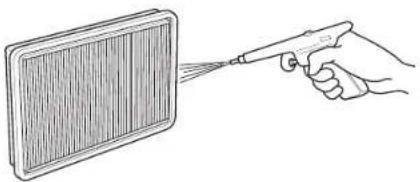
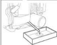
Paper filter element: Tap the filter element several times on a hard surface to remove dirt, or blow compressed air [not exceeding 207 kPa (2.1 kgf/cm², 30 psi)] through the filter element from the clean side that faces the engine. Never try to brush off dirt; brushing will force dirt into the fibers. Replace the paper filter element if it is excessively dirty.
natural_image
Line drawing of a hand holding a spray gun near a rectangular device (no text or symbols)
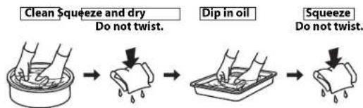
Foam filter element: Clean in warm soapy water, rinse, and allow to dry thoroughly. Or clean in non-flammable solvent and allow to dry. Dip the filter element in clean engine oil, and then squeeze out all excess oil. The engine will smoke when started if too much oil is left in the foam.
- Wipe dirt from the inside of the air cleaner body and cover, using a moist rag. Be careful to prevent dirt from entering the air chamber that leads on the carburetor.
- Reinstall the paper filter element.
- Put the foam filter element on the element holder, and reinstall the element holder on the air cleaner case. Hook the two spring tabs securely.
- Lock the air cleaner cover latch securely.

Recommended Spark Plug: ZFR5F (NGK) FR2A (NGK)
The recommended spark plug has the correct heat range for normal engine operating temperatures.
NOTICE
Incorrect spark plugs can cause engine damage.
If the engine has been running, let it cool before servicing the spark plugs.
For good performance, the spark plugs must be properly gapped and free of deposits.
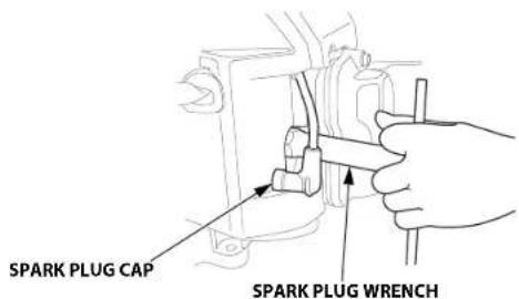
-
Disconnect the spark plug caps, and remove any dirt from around the spark plug area.
-
Remove the spark plugs with a 5/8-inch spark plug wrench.
-
Inspect the spark plugs. Replace them if damaged, badly fouled, if the sealing washer is in poor condition, or if the electrode is worn.
-
Measure the spark plug electrode gaps with a wire-type feeler gauge. Correct the gap, if necessary, by carefully bending the side electrode.
The gap should be:
0.7–0.8 mm
(0.028–0.031 in)
-
Install the spark plugs carefully, by hand, to avoid cross-threading.
-
After the spark plug is seated, tighten with a 5/8-inch spark plug wrench to compress the sealing washer.
When installing a new spark plug, tighten 1/2 turn after the spark plug seats to compress the washer.
When reinstalling the original spark plug, tighten 1/8–1/4 turn after the spark plug seats to compress the washer.
TORQUE: 18.0 N·m (1.8 kgf·m, 13 lbf·ft)
NOTICE
A loose spark plug can overheat and damage the engine. Overtightening the spark plug can damage the threads in the cylinder head.
- Attach the spark plug caps to the spark plugs.
10 ENGLISH
HELPFUL TIPS & SUGGESTIONS
STORING YOUR ENGINE
Storage Preparation
Proper storage preparation is essential for keeping your engine trouble-free and looking good. The following steps will help to keep rust and corrosion from impairing your engine's function and appearance, and will make the engine easier to start when you use it again.
Cleaning
If the engine has been running, allow it to cool for at least half an hour before cleaning. Clean all exterior surfaces, touch up any damaged paint, and coat other areas that may rust with a light film of oil.
NOTICE
Using a garden hose or pressure washing equipment can force water into the air cleaner or muffler opening. Water in the air cleaner will soak the air filter, and water that passes through the air filter or muffler can enter the cylinder, causing damage.
Fuel
NOTICE
Depending on the region where you operate your equipment, fuel formulations may deteriorate and oxidize rapidly. Fuel deterioration and oxidation can occur in as little as 30 days and may cause damage to the carburetor and/or fuel system. Please check with your servicing dealer for local storage recommendations.
Gasoline will oxidize and deteriorate in storage. Deteriorated gasoline will cause hard starting, and it leaves gum deposits that clog the fuel system. If the gasoline in your engine deteriorates during storage, you may need to have the carburetor and other fuel system components serviced or replaced.
The length of time that gasoline can be left in your fuel tank and carburetor without causing functional problems will vary with such factors as gasoline blend, your storage temperatures, and whether the fuel tank is partially or completely filled. The air in a partially filled fuel tank promotes fuel deterioration. Very warm storage temperatures accelerate fuel deterioration. Fuel deterioration problems may occur within a few months, or even less if the gasoline was not fresh when you filled the fuel tank.
Fuel system damage or engine performance problems resulting from neglected storage preparation are not covered under the Distributor's Limited Warranty.
You can extend fuel storage life by adding a gasoline stabilizer that is formulated for that purpose, or you can avoid fuel deterioration problems by draining the fuel tank and carburetor.
Adding a Gasoline Stabilizer to Extend Fuel Storage Life
When adding a gasoline stabilizer, fill the fuel tank with fresh gasoline. If only partially filled, air in the tank will promote fuel deterioration during storage. If you keep a container of gasoline for refueling, be sure that it contains only fresh gasoline.
- Add gasoline stabilizer following the manufacturer's instructions.
- After adding a gasoline stabilizer, run the engine outdoors for 10 minutes to be sure that treated gasoline has replaced the untreated gasoline in the carburetor.
- Stop the engine, and if the fuel tank is equipped with a fuel valve, move the fuel valve to the CLOSED or OFF position.
Draining the Fuel Tank and Carburetor
WARNING
Gasoline is highly flammable and explosive.
You can be burned or seriously injured when handling fuel.
- Stop the engine and let it cool before handling fuel.
- Keep heat, sparks, and flame away.
- Handle fuel only outdoors.
- Keep away from your vehicle.
-
Wipe up spills immediately.
-
Disconnect the fuel line to the engine, and drain the fuel tank into an approved gasoline container. If the fuel tank is equipped with a valve, turn the fuel valve to the OPEN or ON position to enable draining. After draining is completed, reconnect the fuel line.
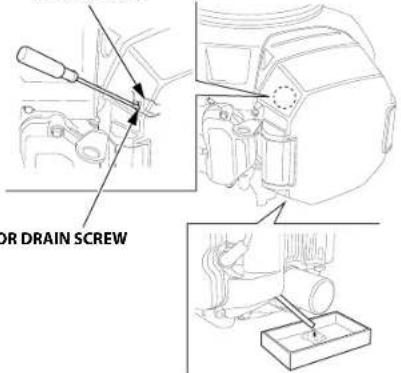
- Loosen the carburetor drain screw, and drain the carburetor into an approved gasoline container. After draining is completed, tighten the carburetor drain screw securely.
CARBURETOR
Engine Oil
- Change the engine oil (see page 8).
- Remove the spark plugs (see page 10).
- Pour 5–10 cm ^3 (5–10 cc, 1–2 teaspoons) of clean engine oil into each cylinder.
- Turn the engine for a few seconds by turning the engine switch to the START position to distribute the oil in the cylinders.
- Reinstall the spark plugs.
Storage Precautions
If your engine will be stored with gasoline in the fuel tank and carburetor, it is important to reduce the hazard of gasoline vapor ignition. Select a well ventilated storage area away from any appliance that operates with a flame, such as a furnace, water heater, or clothes dryer. Also avoid any area with a spark-producing electric motor, or where power tools are operated.
If possible, avoid storage areas with high humidity, because that promotes rust and corrosion.
Keep the engine level in storage. Tilting can cause fuel or oil leakage.
Unless all fuel has been drained from the fuel tank, leave the fuel valve in the CLOSED or OFF position to reduce the possibility of fuel leakage.
With the engine and exhaust system cool, cover the engine to keep out dust. A hot engine and exhaust system can ignite or melt some materials. Do not use a plastic sheet as a dust cover.
A nonporous cover will trap moisture around the engine, promoting rust and corrosion.
Remove the battery and store it in a cool, dry place. Recharge the battery once a month while the engine is in storage. This will help to extend the service life of the battery.
Removal from Storage
Check your engine as described in the BEFORE OPERATION CHECKS section of this manual (see page 4).
If the fuel was drained during storage preparation, fill the tank with fresh gasoline. If you keep a container of gasoline for refueling, be sure it contains only fresh gasoline. Gasoline oxidizes and deteriorates over time, causing hard starting.
If the cylinders were coated with oil during storage preparation, the engine may smoke briefly at startup. This is normal.
TRANSPORTING
If the engine has been running, allow it to cool for at least 15 minutes before loading the engine-powered equipment on the transport vehicle. A hot engine and exhaust system can burn you and can ignite some materials.
Keep the engine level when transporting to reduce the possibility of fuel leakage. If the fuel tank is equipped with a fuel valve, move the fuel valve lever to the CLOSED or OFF position.
TAKING CARE OF UNEXPECTED PROBLEMS
ENGINE WILL NOT START
| Possible Cause Correction |
| Battery discharged. Recharge battery. |
| Fuse burnt out. Replace fuse. | |
| Fuel valve CLOSED or OFF (If equipped). | Move lever to OPEN or ON position. |
| Choke OPEN. Move lever to CLOSED | position unless the engine is warm. |
| Engine switch OFF. Turn engine switch to ON position. |
| Out of fuel. Refuel (p. 7). | |
| Stale fuel; engine stored without treating or draining gasoline, or refueled with stale gasoline. | Drain fuel tank and carburetor (p. 11). Refuel with fresh gasoline (p. 7). |
| Spark plugs faulty, fouled, or improperly gapped. | Gap, or replace spark plugs (p. 10). |
| Spark plugs wet with fuel (flooded engine). | Dry and reinstall spark plugs (p. 10). Start engine with throttle lever in FAST position (p. 5). |
| Fuel filter restricted, carburetor malfunction, ignition malfunction, valves stuck, etc. | Take engine to your servicing dealer, or refer to shop manual. |
ENGINE LACKS POWER
| Possible Cause Correction |
| Filter element(s) restricted. Clean or | replace filter element(s)(p. 9). |
| Stale fuel; engine stored without treating or draining gasoline, or refueled with stale gasoline. | Drain fuel tank and carburetor(p. 11). Refuel with fresh gasoline(p. 7). |
| Fuel filter restricted, carburetor malfunction, ignition malfunction, valves stuck, etc. | Take engine to your servicing dealer, or refer to shop manual. |
Serial Number Location
Record the engine serial number, type and purchase date in the spaces below. You will need this information when ordering parts and when making technical or warranty inquiries.
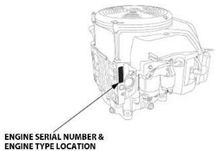
Engine serial number:____—____
Engine type: ____ ____ ____
Date Purchased: ____ / ____ / ____
Battery Connections for Electric Starter
Recommended Battery
Be careful not to connect the battery in reverse polarity, as this will short circuit the battery charging system. Always connect the positive (+) battery cable to the battery terminal before connecting the negative (−) battery cable, so your tools cannot cause a short circuit if they touch a grounded part while tightening the positive (+) battery cable end.
WARNING
A battery can explode if you do not follow the correct procedure, seriously injuring anyone nearby.
Keep all sparks, open flames, and smoking materials away from the battery.
WARNING
The battery contains sulfuric acid (electrolyte), which is highly corrosive and poisonous.
Getting electrolyte in your eyes or on your skin can cause serious burns.
Wear protective clothing and eye protection when working near the battery.
KEEP CHILDREN AWAY FROM THE BATTERY.
WARNING: Battery posts, terminals, and related accessories contain lead and lead compounds. Wash hands after handling.
- Connect the battery positive (+) cable to the starter solenoid terminal as shown.
- Connect the battery negative (−) cable to an engine mounting bolt, frame bolt, or other good engine ground connection.
- Connect the battery positive (+) cable to the battery positive (+) terminal as shown.
- Connect the battery negative (−) cable to the battery negative (−) terminal as shown.
- Coat the terminals and cable ends with grease.

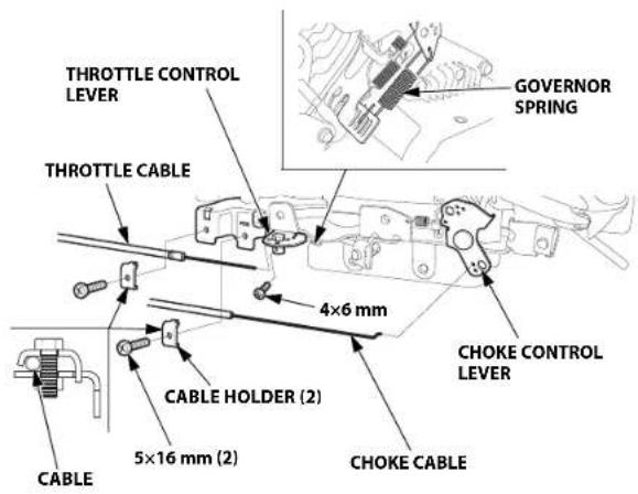
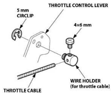
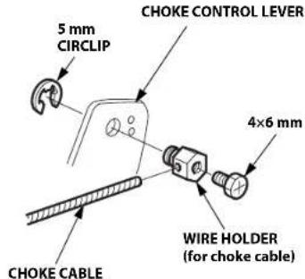
Remote Control Linkage
The throttle and choke control levers are provided with holes for optional cable attachment. The following illustrations show installation examples for a solid wire cable and for a flexible, braided wire cable.
LEFT SIDE CONTROL
RIGHT SIDE CONTROL
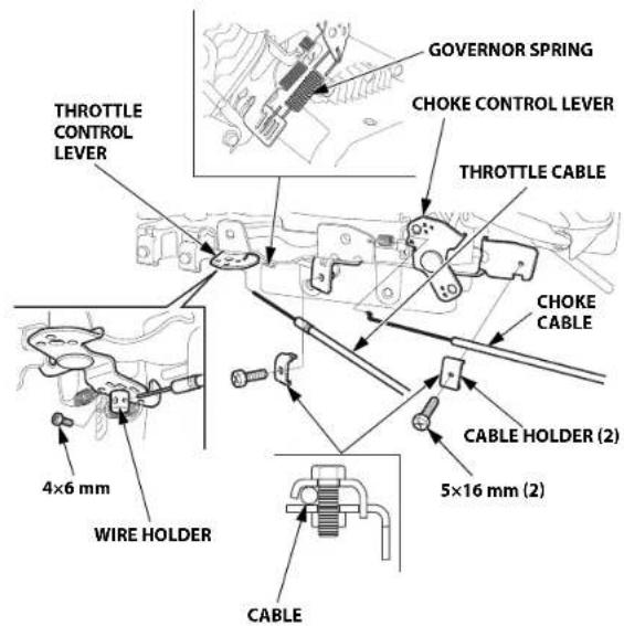
WIRE HOLDER
- For Throttle Cable
- For Choke Cable
Carburetor Modifications for High Altitude Operation
At high altitude, the standard carburetor air-fuel mixture will be too rich. Performance will decrease, and fuel consumption will increase. A very rich mixture will also foul the spark plug and cause hard starting. Operation at an altitude that differs from that at which this engine was certified, for extended periods of time, may increase emissions.
High altitude performance can be improved by specific modifications to the carburetor. If you always operate your engine at altitudes above 610 meters (2,000 feet), have your servicing dealer perform this carburetor modification. This engine, when operated at high altitude with the carburetor modifications for high altitude use, will meet each emission standard throughout its useful life.
Even with carburetor modification, engine horsepower will decrease about 3.5% for each 300 meter (1,000 foot) increase in altitude. The effect of altitude on horsepower will be greater than this if no carburetor modification is made.
NOTICE
When the carburetor has been modified for high altitude operation, the air-fuel mixture will be too lean for low altitude use. Operation at altitudes below 610 meters (2,000 feet) with a modified carburetor may cause the engine to overheat and result in serious engine damage. For use at low altitudes, have your servicing dealer return the carburetor to original factory specifications.
Emission Control System Warranty
Your new Honda complies with both the U.S. EPA and State of California emission regulations. American Honda provides the same emission warranty coverage for Honda Power Equipment engines sold in all 50 states. In all areas of the United States, your Honda Power Equipment engine is designed, built, and equipped to meet the U.S. EPA and California Air Resources Board emission standard for spark ignited engines.
Warranty Coverage
Honda Power Equipment engines certified to CARB and U.S. EPA regulations are covered by this warranty to be free from defects in materials and workmanship that may keep it from meeting the applicable U.S. EPA and CARB emissions requirements for a minimum of 2 years or the length of the Honda Power Equipment Distributor's Limited Warranty, whichever is longer, from the original date of delivery to the retail purchaser. This warranty is transferable to each subsequent purchaser for the duration of the warranty period. Warranty repairs will be made without charge for diagnosis, parts, and labor. Information about how to make a warranty claim, as well as a description of how a claim can be made and/or how service can be provided, can be obtained by contacting an authorized Honda Power Equipment dealer or by contacting American Honda at the following:
Email: powerequipmentemissions@ahm.honda.com
Telephone: (888) 888-3139
The covered components include all components whose failure would increase an engine's emissions of any regulated pollutant or evaporative emissions. A list of specific components can be found in the separately included emissions warranty statement.
Specific warranty terms, coverage, limitations and manner of seeking warranty service are also set forth in the separately included emissions warranty statement. In addition, the emissions warranty statement can also be found on the Honda Power equipment website or at the following link:
http://powerequipment.honda.com/support/warranty
Source of Emissions
The combustion process produces carbon monoxide, oxides of nitrogen, and hydrocarbons. Control of hydrocarbons and oxides of nitrogen are very important because, under certain conditions, they react to form photochemical smog when subjected to sunlight.
Carbon monoxide does not react in the same way, but it is toxic.
Honda utilizes appropriate air/fuel ratios and other emissions control systems to reduce the emissions of carbon monoxide, oxides of nitrogen, and hydrocarbons.
Additionally, Honda fuel systems utilize components and control technologies to reduce evaporative emissions.
The U.S. and California Clean Air Acts, and Environment and Climate Change Canada (ECCC)
U.S. EPA, California and Canadian regulations require all manufacturers to furnish written instructions describing the operation and maintenance of emission control systems.
The following instructions and procedures must be followed in order to keep the Honda engine emissions within the emission standards.
Tampering and Altering
NOTICE
Tampering is a violation of federal and California law.
Tampering with or altering the emission control system may increase emissions beyond the legal limit. Among those acts that constitute tampering are:
- Removal or alteration of any part of the intake, fuel, or exhaust systems.
- Altering or defeating the governor linkage or speed-adjusting mechanism to cause the engine to operate outside its design parameters.
Problems That May Affect Emissions
If you are aware of any of the following symptoms, have your engine inspected and repaired by your servicing dealer.
- Hard starting or stalling after starting.
• Rough idle
- Misfiring or backfiring under load.
• Afterburning (backfiring).
- Black exhaust smoke or high fuel consumption.
Replacement Parts
The emissions control systems on your new Honda engine were designed, built, and certified to conform with U.S. EPA, California, and Canadian emissions regulations. We recommend the use of Honda Genuine parts whenever you have maintenance done. These original-design replacement parts are manufactured to the same standards as the original parts, so you can be confident of their performance. Honda cannot deny coverage under the emission warranty solely for the use of non-Honda replacement parts or service performed at a location other than an authorized Honda dealership; you may use comparable U.S. EPA certified parts, and have service performed at non-Honda locations. However, the use of replacement parts that are not of the original design and quality may impair the effectiveness of your emissions control system.
A manufacturer of an aftermarket part assumes the responsibility that the part will not adversely affect emissions performance. The manufacturer or rebuilder of the part must certify that use of the part will not result in a failure of the engine to comply with emissions regulations.
Maintenance
As the power equipment engine owner, you are responsible for completing all required maintenance listed in your owner's manual. Honda recommends that you retain all receipts covering maintenance on your power equipment engine, but Honda cannot deny warranty coverage solely for the lack of receipts or for your failure to ensure that all scheduled maintenance has been completed. Follow the MAINTENANCE SCHEDULE on page 6. Remember that this schedule is based on the assumption that your engine will be used for its designed purpose. Sustained high-load or high-temperature operation, or use in dusty conditions, will require more frequent service.
Air Index
(Models certified for sale in California)
An Air Index Information label is applied to engines certified to an emission durability time period in accordance with the requirements of the California Air Resources Board.
The bar graph is intended to provide you, our customer, the ability to compare the emissions performance of available engines. The lower the Air Index, the less pollution.
The durability description is intended to provide you with information relating to the engine's emission durability period.
The descriptive term indicates the useful life period for the engine's emission control system. See your Emission Control System Warranty for additional information.
| Descriptive Term Applicable to Emissions Durability Period |
| Moderate 50 hours (0–80 cc, inclusive)125 hours (greater than 80 cc) |
| Intermediate 125 hours (0–80 cc, inclusive)250 hours (greater than 80 cc) |
| Extended 300 hours (0–80 cc, inclusive)500 hours (greater than 80 cc)1,000 hours (225 cc and greater) |
The Air Index Information hang tag/label must remain on the engine until it is sold. Remove the hang tag before operating the engine.
Specifications
GXV630 (QAF-Type)
| Length×Width×Height 443×420×446 mm(17.4×16.5×17.6 in) |
| Dry mass [weight] 45.7 kg (100.8 lbs) |
| Engine type 4-stroke, overhead valve,2 cylinders (90° V-Twin) |
| Displacement[Bore×Stroke] | 688.0 cm ^3 (41.97 cu-in)[78.0×72.0 mm (3.07×2.83 in)] |
| Net power(in accordance with SAE J1349*) | 15.5 kW (21.1 PS, 20.8 bhp)at 3,600 min ^-1 (rpm) |
| Max. Net torque(in accordance with SAE J1349*) | 48.3 N·m (4.93 kgf·m, 35.6 lbf·ft) at2,500 min ^-1 (rpm) |
| Engine oil capacity Without oil filter replacement:1.7 L (1.8 US qt, 1.5 Imp qt)With oil filter replacement:1.9 L (2.0 US qt, 1.7 Imp qt) |
| Cooling system Forced air | |
| Ignition system CDI type magneto ignition |
| PTO shaft rotation Counterclockwise |
GXV690 (TAF-Type)
| Length×Width×Height 443 | ×420×463 mm(17.4×16.5×18.2 in) |
| Dry mass [weight] 45.9 kg (101.2 lbs) |
| Engine type 4-stroke, overhead valve,2 cylinders (90° V-Twin) |
| Displacement[Bore×Stroke] | 688.0 cm3 (41.97 cu-in)[78.0×72.0 mm (3.07×2.83 in)] |
| Net power(in accordance with SAE J1349*) | 16.5 kW (22.4 PS, 22.1 bhp)at 3,600 min-1(rpm) |
| Max. Net torque(in accordance with SAE J1349*) | 48.3 N·m (4.93 kgf·m, 35.6 lbf·ft) at2,500 min-1(rpm) |
| Engine oil capacity Without oil filter replacement:1.7 L (1.8 US qt, 1.5 Imp qt)With oil filter replacement:1.9 L (2.0 US qt, 1.7 Imp qt) |
| Cooling system Forced air | |
| Ignition system CDI type magneto ignition |
| PTO shaft rotation Counterclockwise |
* The power rating of the engine indicated in this document is the net power output tested on a production engine for the engine model and measured in accordance with SAE J1349 at 3,600 min ^-1 (rpm) (Net Power) and at 2,500 min ^-1 (rpm) (Max. Net Torque). Mass production engines may vary from this value.
Actual power output for the engine installed in the final machine will vary depending on numerous factors, including the operating speed of the engine in application, environmental conditions, maintenance, and other variables.
Tuneup Specifications GXV630/690
| ITEM SPECIFICATION MAINTENANCE | |
| Spark plug gap 0.7- | 0.8 mm(0.028–0.031 in) | Refer to page 10. |
| Idle speed | 1,400 ± 150 min^-1 (rpm) | See your servicing dealer |
| Valve clearance (cold) | IN: 0.08 ± 0.02 mm EX: 0.10 ± 0.02 mm |
| Other specifications | No other adjustments needed. |
Quick Reference Information
| Fuel Unleaded | gasoline (Refer to page 7). |
| U.S. Pump | octane rating 86 or higher |
| Except U.S. | Research octane rating 91 or higher |
| Pump octane rating 86 or higher |
| Engine oil SAE | 10W-30, API SJ or later, for general use.Refer to page 7. |
| Spark plug ZFRSF (NGK), FR2A (NGK) |
| Maintenance B | Before each use:Check engine oil level. Refer to page 7.Check air filter. Refer to page 9. |
| First 20 hours:Change engine oil. Refer to page 8. |
| Subsequent:Refer to the maintenance schedule on page 6. |
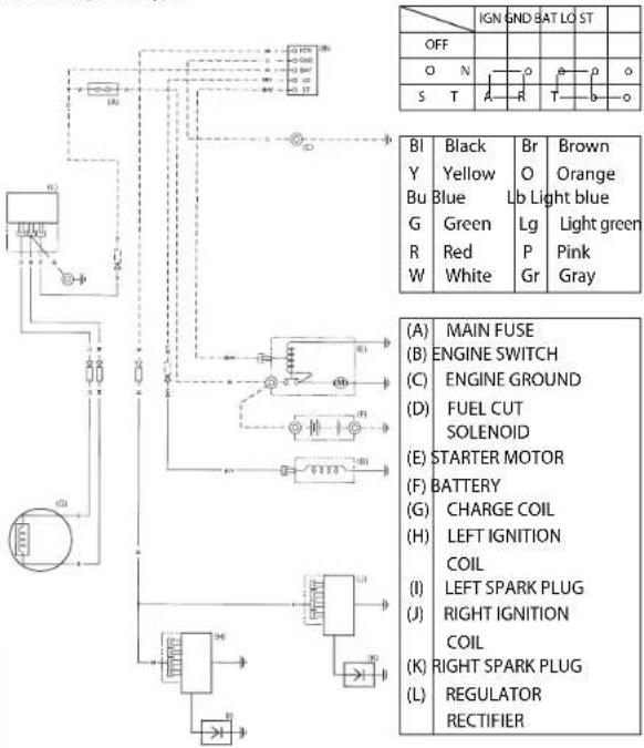
Wiring Diagrams
2.7 A Charge Coil Type
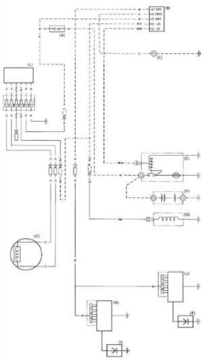
17 A Charge Coil Type
flowchart
graph TD
    A["Power Supply"] --> B["Switch"]
    B --> C["Resistor 1"]
    B --> D["Resistor 2"]
    B --> E["Resistor 3"]
    B --> F["Resistor 4"]
    B --> G["Resistor 5"]
    B --> H["Resistor 6"]
    B --> I["Resistor 7"]
    B --> J["Resistor 8"]
    B --> K["Resistor 9"]
    B --> L["Resistor 10"]
    M["Motor Control"] --> N["Switch"]
    N --> O["Resistor 1"]
    N --> P["Resistor 2"]
    N --> Q["Resistor 3"]
    N --> R["Resistor 4"]
    N --> S["Resistor 5"]
    N --> T["Resistor 6"]
    N --> U["Resistor 7"]
    N --> V["Resistor 8"]
    N --> W["Resistor 9"]
    N --> X["Resistor 10"]
    Y["Current Source"] --> Z["Ground"]
    AA["Current Source"] --> AB["Ground"]
    AC["Current Source"] --> AD["Ground"]
    AE["Current Source"] --> AF["Ground"]
    AG["Current Source"] --> AH["Ground"]
    AI["Current Source"] --> AJ["Ground"]
    AK["Current Source"] --> AL["Ground"]
    AM["Current Source"] --> AN["Ground"]
    AO["Current Source"] --> AP["Ground"]
    AQ["Current Source"] --> AR["Ground"]
    AS["Current Source"] --> AT["Ground"]
    AU["Current Source"] --> AV["Ground"]
    AW["Current Source"] --> AX["Ground"]
    AY["Power Supply"] --> AZ["A"]
    BA["Power Supply"] --> BB["B"]
    BC["Power Supply"] --> BD["C"]
    BE["Power Supply"] --> BF["D"]
    BG["Power Supply"] --> BH["E"]
    BI["Power Supply"] --> BJ["F"]
    BK["Power Supply"] --> BL["G"]
    BM["Power Supply"] --> BN["H"]
    BO["Power Supply"] --> BP["I"]
    BQ["Power Supply"] --> BR["J"]
    BS["Power Supply"] --> BT["K"]
    BU["Power Supply"] --> BV["L"]
United States, Puerto Rico, and U.S. Virgin Islands:
Visit our website: www.honda-engines.com
Canada:
Call (888) 9HONDA9
or visit our website: www.honda.ca
For European Area:
Visit our website: http://www.honda-engines-eu.com
Servicing dealership personnel are trained professionals. They should be able to answer any question you may have. If you encounter a problem that your dealer does not solve to your satisfaction, please discuss it with the dealership's management. The Service Manager, General Manager, or Owner can help.
Almost all problems are solved in this way.
United States, Puerto Rico, and U.S. Virgin Islands:
If you are dissatisfied with the decision made by the dealership's management, contact the Honda Regional Engine Distributor for your area.
If you are still dissatisfied after speaking with the Regional Engine Distributor, you may contact the Honda Office as shown.
All Other Areas:
If you are dissatisfied with the decision made by the dealership's management, contact the Honda Office as shown.
《Honda's Office》
When you write or call, please provide this information:
- Equipment manufacturer's name and model number that the engine is mounted on
• Engine model, serial number, and type (see page 13)
• Name of dealer who sold the engine to you
- Name, address, and contact person of the dealer who services your engine
- Date of purchase
- Your name, address and telephone number
• A detailed description of the problem
United States, Puerto Rico, and U.S. Virgin Islands:
American Honda Motor Co., Inc.
Power Equipment Division
Customer Relations Office
4900 Marconi Drive
Alpharetta, GA 30005-8847
Or telephone:
(770) 497-6400
(888) 888-3139 Toll free
M-F 8:30am - 7:00pm ET
Canada:
Honda Canada, Inc.
Please visit www.honda.ca
for address information
Telephone: (888) 9HONDA9 Toll free
(888) 946-6329
Facsimile: (877) 939-0909 Toll free
For European Area:
Honda Motor Europe Logistics NV.
European Engine Center
http://www.honda-engines-eu.com
All Other Areas:
Please contact the Honda distributor in your area for assistance.
HONDA
18 ENGLISH


INTRODUZIONE
natural_image
Technical line drawing of a mechanical component with no visible text or symbols
ITALANO
AVVERTENZA:
natural_image
Line drawing of a hand holding a spray gun near a rectangular panel (no text or symbols)
E-mail: powerequipmentemissions@ahm.honda.com
Telefono: (888) 888-3139
American Honda Motor Co., Inc.
Power Equipment Division
Customer Relations Office
4900 Marconi Drive
Alpharetta, GA 30005-8847
O telefono:
(770) 497-6400
(888) 888-3139 (numero verde)
L-V 8:30am - 7:00pm ET
Canada:
Honda Canada, Inc.
Honda Motor Europe Logistics NV.
European Engine Center
http://www.honda-engines-eu.com
natural_image
Technical line drawing of a mechanical component with no visible text or symbols
FRANGALS

AVERTISSEMENT:
natural_image
Line drawing of a hand using a spray gun to spray liquid onto a grid-patterned panel (no text or symbols)
VIS DE VIDANGE DU CARBURATEUR
Huile moteur
natural_image
Technical line drawing of a mechanical assembly with no visible text or symbols
EMPLACEMENT DU NUMERO DE SERIE ET
DU TYPE DE MOTEUR
E-mail: powerequipmentemissions@ahm.honda.com
American Honda Motor Co., Inc.
Power Equipment Division
Customer Relations Office
4900 Marconi Drive
Alpharetta, GA 30005-8847
Ou téléphone :
(770) 497-6400
(888) 888-3139 sans frais
M-F 8:30 - 19:00 ET
Canada :
Honda Canada, Inc.
Visitez notre site Web www.honda.ca
Honda Motor Europe Logistics NV.
European Engine Center
http://www.honda-engines-eu.com
natural_image
Technical line drawing of a mechanical component with no visible text or symbols

WARNUNG:
natural_image
Line drawing of a hand holding a spray gun near a grid-patterned panel (no text or symbols)
natural_image
Technical line drawing of a mechanical assembly with tool and component details (no text or symbols)
VERGASERABLASSSCHRAUBE
Motoröl
natural_image
Technical line drawing of a mechanical assembly with no visible text or symbols
POSITION VON MOTORSERIENNUMMER UND POSITION, ANGABEN ZUM MOTORTYP
Motorseriennummer: ____ — ____ ____
Motortyp: ____ ____ ____
Kaufdatum: ____ / ____ / ____
U.S. Clean Air Act, California Clean Air Act und Environment and Climate Change Canada (ECCC)
American Honda Motor Co., Inc.
Power Equipment Division
Customer Relations Office
4900 Marconi Drive
Alpharetta, GA 30005-8847
Oder telefonisch:
(770) 497-6400
Honda Motor Europe Logistics NV.
European Engine Center
http://www.honda-engines-eu.com
natural_image
Technical line drawing of a mechanical component with no visible text or symbols

ADVERTENCIA:

natural_image
Line drawing of a hand spraying water onto a rectangular panel (no text or symbols)
http://powerequipment.honda.com/support/warranty
Honda Motor Europe Logistics NV.
European Engine Center
http://www.honda-engines-eu.com
natural_image
Technical line drawing of a mechanical component with no visible text or symbols
⚠ WAARSCHUWING: ⚠
natural_image
Line drawing of a hand spraying water onto a rectangular panel (no text or symbols)
http://powerequipment.honda.com/support/warranty
Emissiebron
American Honda Motor Co., Inc.
Power Equipment Division
Customer Relations Office
4900 Marconi Drive
Alpharetta, GA 30005-8847
Of telefoon:
(770) 497-6400
(888) 888-3139 gratis
Ma-Vr 8:30 - 19:00 Eastern Time
Canada:
Honda Canada, Inc.
Honda Motor Europe Logistics NV.
European Engine Center
http://www.honda-engines-eu.com
Alle overige gebieden: