
CM7 - Speaker BOWERS & WILKINS - Free user manual and instructions
Find the device manual for free CM7 BOWERS & WILKINS in PDF.

| Product type | Floor-standing loudspeaker |
| Brand | Bowers & Wilkins |
| Model | CM7 |
| Installation type | Floor-standing, with decoupling spikes |
| Number of ways | Not specified (likely 2.5 or 3-way) |
| Connectivity | Single or bi-wiring connections (2 pairs of terminals) |
| Impedance | Do not go below the minimum recommended by the amplifier |
| Polarity | Observe + and - for correct stereo image |
| Positioning | Equilateral triangle with listening position; distance of 1.5 to 3 m between speakers |
| Distance from walls | Approximately 50 cm from rear and side walls |
| Magnetic field | Keep at least 50 cm away from CRT screens, tapes, etc. |
| Bass adjustment | Supplied foam plugs to reduce bass; partial use with rings |
| Break-in period | About 15 hours of normal use for the suspensions |
| Maintenance | Regular dusting; clean grille with a brush; avoid touching the drivers |
| Cabinet material | Real wood veneer with anti-UV lacquer |
| Environmental protection | RoHS and WEEE compliant; recyclable |
| Warranty | 5 years (labor and parts) / 2 years for electronic components |
| Supplied accessories | 4 M6 spikes, 4 rubber feet, 4 lock nuts, foam plugs |
| Bi-wiring | Possible by removing the links between terminals |
Frequently Asked Questions - CM7 BOWERS & WILKINS
User questions about CM7 BOWERS & WILKINS
0 question about this device. Answer the ones you know or ask your own.
Ask a new question about this device
Download the instructions for your Speaker in PDF format for free! Find your manual CM7 - BOWERS & WILKINS and take your electronic device back in hand. On this page are published all the documents necessary for the use of your device. CM7 by BOWERS & WILKINS.
USER MANUAL CM7 BOWERS & WILKINS
natural_image
Close-up of a metallic speaker grille with concentric rings and textured base (no text or symbols visible)Figure 1a
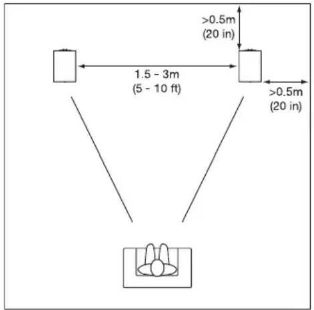
Figure 1b
natural_image
Simple diagram showing two vertical lines with a central box containing a rabbit silhouette (no text or symbols)Figure 2a
AMPLIFIER
Figure 2b
AMPLIFIER
Figure 3a
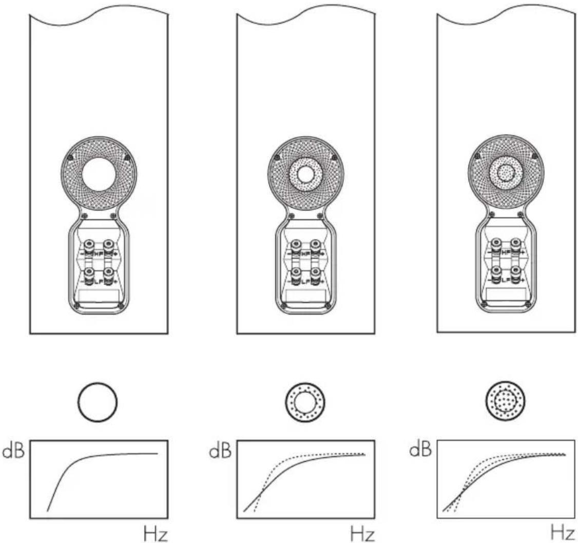
Figure 3b
natural_image
Diagram of a cylindrical pipe with a dotted cross-section and an arrow indicating direction (no text or symbols)Contents
English
Owner's Manual......2
Limited Warranty......4
Français
Specifications .....51–52
English
Owner's manual
Dear Customer,
Thank you for choosing B&W. Please read this manual fully before unpacking and installing the product. It will help you to optimise its performance. B&W maintains a network of dedicated distributors in over 60 countries who will be able to help you should you have any problems your dealer cannot resolve.
Environmental Information

All B&W products are designed to comply with international directives on the Restriction of Hazardous Substances
(RoHS) in electrical and electronic equipment and the disposal of Waste Electrical and Electronic Equipment (WEEE). These symbols indicate compliance and that the products must be appropriately recycled or processed in accordance with these directives. Consult your local waste disposal authority for guidance.
Carton Contents
Check in the carton for:
1 Two-part foam plug
1 Accessory pack containing:
4 M6 spike feet
4 Rubber feet
4 Lock nuts (10mm across flats)
and in the CM9 only
1 Plinth
1 Accessory pack containing:
1 Allen key
4 M6 x 35mm screws
4 Plain washers
4 Shakeproof washers
Speaker Installation
The speakers are intended to be floor mounted only. It is important to ensure that the speakers stand firmly on the floor using the spike feet supplied whenever possible. In addition, the taller CM9 should have its plinth fitted for proper stability.
To attach the plinth, stand the speaker on its top taking care not to damage the cabinet or the drive units during handling. Align the plinth with its attachment holes in the underside of the cabinet, ensuring that the arrow on the underside of the plinth points forwards. Secure the plinth using the screws and washers supplied. Fit the shakeproof washers between the plain washers and the screw heads. Tighten the screws using the Allen key supplied.
The spike feet are designed to pierce carpet and rest on the floor surface. Initially, screw the lock nuts onto the spikes enough to leave the nuts floating just above the carpet when the spikes are resting on the floor beneath. Screw the spikes fully into the threaded inserts in the base of the CM7 cabinet or the plinth of the CM9. If the cabinet rocks when placed on the floor, unscrew the two spikes that do not touch the
floor until the cabinet rests firmly without rocking. Finally, lock the nuts against the cabinet. It may be more convenient to fit and adjust the spike feet after speaker positioning has been optimised.
If there is no carpet and you wish to avoid scratching the floor surface, use either a protective metal disc (a coin perhaps) between the spike and the floor, or use the supplied rubber feet. Fit the rubber feet and level the cabinet in the same manner as with the spike feet.
Speaker Positioning
Adjustment of speaker position following initial installation will probably further improve the sound quality and is usually worthwhile.
In either stereo or home theatre installations, try to ensure that the immediate surroundings of each speaker are similar in acoustic character. For example, if one speaker is adjacent to bare walls while the other is adjacent to soft furnishings and curtains, both the overall sound quality and the stereo image are likely to be compromised.
Conventional Stereo Systems
To begin with, the speakers should be positioned between 1.5m and 3m apart at two corners of an equilateral triangle completed by the listening area at the third corner. The speakers should be approximately 0.5m away from the back wall, and at least 0.5m away from any side walls. Figure 1a illustrates this arrangement.
Home Theatre Systems
If the speakers are to be used for the front channels in a home theatre system, they should be placed closer together than for 2-channel audio, because the surround channels tend to widen the image. Positioning the speakers within approximately 0.5m of the sides of the screen will also help keep the sound image in scale with the visual image. As with conventional stereo positioning, the speakers should ideally be at least 0.5m away from any side walls. If the speakers are preferred placed against the back wall and this location results in over emphasized bass, see the Fine Tuning section of this manual for information on using the foam plugs.
Stray Magnetic Fields
The speaker drive units create stray magnetic fields that extend beyond the boundaries of the cabinet. We recommend you keep magnetically sensitive articles (CRT television and computer screens, computer discs, audio and video tapes, swipe cards and the like) at least 0.5m from the speaker. LCD and plasma screens are not affected by magnetic fields.
Connections
All connections should be made with the equipment switched off.
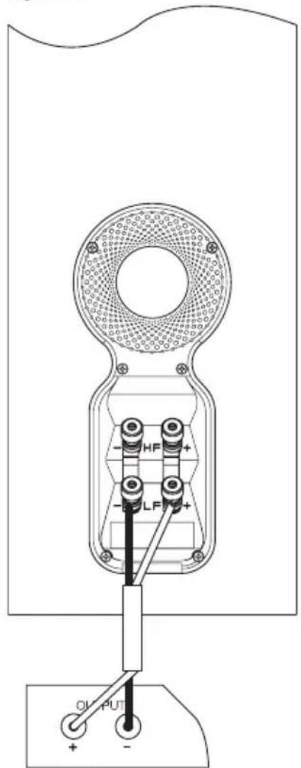
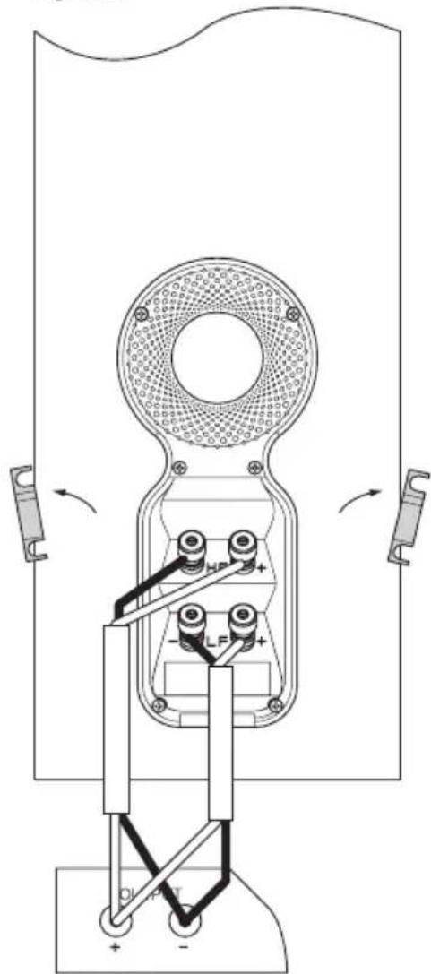
There are 2 linked pairs of terminals on the back of the speaker. For conventional connection, the terminal links should remain in place (as delivered) and just one pair of terminals connected to the amplifier. For bi-wire connection, the terminal links should be removed and
each pair of terminals connected to the amplifier independently. Bi-wiring can improve the resolution of low-level detail. Figures 2a and 2b illustrate conventional and bi-wire connection.
Ensure that the positive terminals on the speaker (marked + and coloured red) are connected to the positive output terminal on the amplifier and the negative terminals on the speaker (marked – and coloured black) are connected to the negative output terminal on the amplifier. Incorrect connection can result in poor imaging and loss of bass.
Ask your dealer for advice when selecting speaker cable. Keep its total impedance below the maximum recommended in the speaker specification and use a low inductance cable to avoid attenuation of high frequencies.
Fine Tuning
Before fine tuning, make sure that all the connections in the installation are correct and secure.
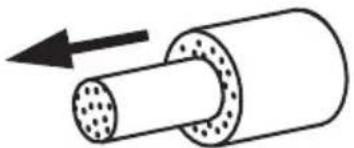
Moving the speakers further from the walls will generally reduce the volume of bass. Space behind the speakers will also help to create an aural impression of depth. Conversely, moving the speakers closer to the walls will increase the volume of bass. If you want to reduce the volume of bass without moving the speakers further from the wall, fit the foam plugs or, for less severe bass reduction, the foam rings in the port tubes. Fitting a foam plug or ring in a port tube is illustrated in Figure 3.
If the bass seems uneven with frequency this will most probably be due to resonance modes in the listening room. Even small changes in the position of the speakers or the listening position can have a profound effect on how these resonances affect the sound. Try moving the listening position or locating the speakers along a different wall. The presence and position of large pieces of furniture can also influence resonance modes.
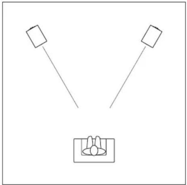
If the central image lacks focus, try moving the speakers closer together or angling them inward so that they point at a location just in front of the listening position. Figure 1b illustrates speakers angled inwards.
If the sound is too bright, increasing the amount of soft furnishing in the room (heavier curtains for example) may help balance the sound. Conversely, reducing the amount of soft furnishing may help brighten a dull sound.
Some rooms suffer from “flutter echoes” – echoes that “bounce” between parallel room boundaries. Flutter echoes can colour the sound of the speakers in the room. Test for flutter echoes by standing in the middle of the room and clapping your hands. Flutter echoes can be reduced by placing irregular shaped items or non-reflective surfaces, bookshelves, rugs or pictures for example, on one of the offending walls or floor.
Ensure that the speaker stands firmly on the floor. Use carpet piercing spikes if appropriate and adjust them to take up any unevenness.
Running-in Period
The performance of the speaker will change subtly during the initial listening period. If the speaker has been stored in a cold environment, the damping compounds and suspension materials of the drive units will take some time to recover their correct mechanical properties. The drive unit suspensions will also loosen up during the first hours of use. The time taken for the speaker to achieve its intended performance will vary depending on previous storage conditions and how it is used. As a guide, allow up to a week for the temperature effects to stabilise and 15 hours of average use for the mechanical parts to attain their intended design characteristics.
However, longer run-in periods (as long as a month) have been reported and there is evidence to suggest that this has little to do with the speaker changing and more to do with the listener getting used to the new sound. This is especially so with highly revealing speakers such as these, where there may be a significant increase in the amount of detail compared with what the listener has previously been used to; the sound may at first appear too “up front” and perhaps a little hard. After an extended period of time, the sound will seem to mellow, but without losing clarity and detail.
Aftercare
The cabinet surfaces usually only require dusting. If you wish to use an aerosol or other cleaner, remove the grille first by gently pulling it away from the cabinet. Spray aerosols onto the cleaning cloth, not directly onto the product. Test a small area first, as some cleaning products may damage some of the surfaces. Avoid products that are abrasive, or contain acid, alkali or anti-bacterial agents. Do not use cleaning agents on the drive units. The grille fabric may be cleaned with a normal clothes brush whilst the grille is detached from the cabinet. Avoid touching the drive units, especially the tweeter, as damage may result.
In order to avoid the risk of the surface finish cracking, keep the product away from sources of direct heat such as radiators and warm air vents. Whenever Bowers & Wilkins speakers are finished in real wood, the finest veneers are selected and treated with an ultra-violet resistant lacquer to minimise changes in colour over time. Nevertheless, like all natural materials, the veneer will respond to its environment and a degree of colour change is to be expected. The effect may be particularly noticeable where the area covered by the grille, or areas kept in shadow, change more slowly than other areas. Colour differences may be rectified by exposing all the veneer surfaces equally and evenly to sunlight until the colour is uniform. This process can take several days or even weeks, but may be accelerated by careful use of an ultra-violet lamp.
Limited Warranty
This product has been designed and manufactured to the highest quality standards. However, if something does go wrong with this product, B&W Group Ltd. and its national distributors warrant free of charge labour (exclusion may apply) and replacement parts in any country served by an official B&W distributor.
This limited warranty is valid for a period of five years from the date of purchase or two years for electronics including amplified loudspeakers.
Terms and Conditions
1 The warranty is limited to the repair of the equipment. Neither transportation, nor any other costs, nor any risk for removal, transportation and installation of products is covered by this warranty.
2 This warranty is only valid for the original owner. It is not transferable.
3 This warranty will not be applicable in cases other than defects in materials and/or workmanship at the time of purchase and will not be applicable:
a. for damages caused by incorrect installation, connection or packing,
b. for damages caused by any use other than correct use described in the user manual, negligence, modifications, or use of parts that are not made or authorised by B&W,
c. for damages caused by faulty or unsuitable ancillary equipment,
d. for damages caused by accidents, lightning, water, fire heat, war, public disturbances or any other cause beyond the reasonable control of B&W and its appointed distributors,
e. for products whose serial number has been altered, deleted, removed or made illegible,
f. if repairs or modifications have been executed by an unauthorised person.
4 This guarantee complements any national/regional law obligations of dealers or national distributors and does not affect your statutory rights as a customer.
How to claim repairs under warranty
Should service be required, please follow the following procedure:
1 If the equipment is being used in the country of purchase, you should contact the B&W authorised dealer from whom the equipment was purchased.
2 If the equipment is being used outside the country of purchase, you should contact the B&W national distributor in the country of residence, who will advise where the equipment can be serviced. You can call B&W in the UK or visit our web site to get the contact details of your local distributor.
To validate your warranty, you will need to produce the warranty booklet completed and stamped by your dealer on the date of purchase.
Sistemi Home Theatre
EU DECLARATION OF CONFORMITY
We,
B&W Group Ltd.
whose registered office is situated at
Dale Road, Worthing, West Sussex, BN11 2BH, United Kingdom
declare under our sole responsibility that the products:
CM7, CM9
comply with the EU Electro-Magnetic Compatibility (EMC) Directive 89/336/EEC, in pursuance of which the following standards have been applied:
EN 61000-6-1 : 2001
EN 61000-6-3 : 2001
EN 55020:2002
EN 55013:2001
and comply with the EU General Product Safety 2001/95/EC, in pursuance of which the following standard has been applied:
EN 60065:2002
This declaration attests that the manufacturing process quality control and product documentation accord with the need to assure continued compliance.
The attention of the user is drawn to any special measures regarding the use of this equipment that may be detailed in the owner's manual.
Signed:

G Edwards
Executive Vice President, Operations
B&W Group Ltd.
CM7
Technical features Nautilus™ tube loaded aluminium dome tweeter
Kevlar® brand fibre cone FST midrange
Flowport™
Description 3-way vented-box system
Drive units 1x ø25mm (1 in) aluminium dome high-frequency
1x ø130mm (5 in) woven Kevlar® cone FST midrange
1x ø165mm (6.5 in) paper/Kevlar® cone bass
Frequency range -6dB at 34Hz and 50kHz
Frequency response 62Hz - 22kHz ±3dB on reference axis
Dispersion Within 2dB of reference response
Horizontal: over 60° arc
Vertical: over 10° arc
Sensitivity 88dB spl (2.83V, 1m)
Harmonic distortion 2nd and 3rd harmonics (90dB, 1m)
<1% 100Hz - 22kHz
<0.5% 150Hz - 20kHz
Nominal impedance 8Ω (minimum 3.0Ω)
Crossover frequencies 350Hz, 4kHz
Bass unit 3rd order low pass
Midrange 2nd-order high-pass, 1st order low-pass
Tweeter 1st-order high-pass
Recommended amplifier power 30W - 150W into 8Ωon unclipped programme
Max. recommended
cable impedance 0.1Ω
Dimensions Height: 910mm (35.8 in) not including feet
Width: 200mm (7.9 in)
Depth: 280mm (11 in) cabinet only
300mm (11.8 in) including grille and terminals
Net weight 20kg (44 lb)
natural_image
Vertical stack of three circular speakers or fans, no text or symbols visibleCM9
Technical features Nautilus™ tube loaded aluminium dome tweeter
Kevlar® brand fibre cone FST midrange
Flowport™
Description 3-way vented-box system
Drive units 1x ø25mm (1 in) aluminium dome high-frequency
1x ø160mm (6 in) woven Kevlar® cone FST midrange
2x ø165mm (6.5 in) paper/Kevlar® cone bass
Frequency range -6dB at 30Hz and 50kHz
Frequency response 56Hz - 22kHz ±3dB on reference axis
Dispersion Within 2dB of reference response
Horizontal: over 60° arc
Vertical: over 10° arc
Sensitivity 89dB spl (2.83V, 1m)
Harmonic distortion 2nd and 3rd harmonics (90dB, 1m)
<1% 90Hz - 22kHz
<0.5% 120Hz - 20kHz
Nominal impedance 8Ω (minimum 3Ω)
Crossover frequencies 350Hz, 4kHz
Recommended amplifier power 30W - 200W into 8Ωon unclipped programme
Max. recommended
cable impedance 0.1Ω
Dimensions Height: 990mm (39 in) cabinet only
1025mm (40.4 in) including plinth but not feet
Width: 200mm (7.9 in) cabinet only
320mm (12.6 in) including plinth
Depth: 300mm (11.8 in) cabinet only
321mm (12.6 in) inc. grille and terminals but not plinth
370mm (14.6 in) including plinth
Net weight 26.6kg (58.5 lb)
Bowers & Wilkins
B&W Group Ltd
Dale Road
Worthing West Sussex
BN11 2BH England
T +44 (0) 1903 221 800
F +44 (0) 1903 221 801
info@bwgroup.com
www.bowers-wilkins.com
B&W Group (UK Sales)
T +44 1903 221 500
E uksales@bwgroup.com
B&W Group North America
T +1 978 664 2870
E marketing@bwgroupusa.com
B&W Group Asia Ltd
T +852 2 869 9916
E info@bwgroup.hk
Kevlar is a registered trademark of DuPont.
Nautilus is a trademark of B&W Group Ltd.
Copyright © B&W Group Ltd. E&OE
Printed in China.

- Contents
- English
- Français
- Owner's manual
- Environmental Information
- Carton Contents
- Speaker Installation
- Speaker Positioning
- Conventional Stereo Systems
- Home Theatre Systems
- Stray Magnetic Fields
- Connections
- Fine Tuning
- Running-in Period
- Aftercare
- Limited Warranty
- Terms and Conditions
- How to claim repairs under warranty
- Sistemi Home Theatre
- EU DECLARATION OF CONFORMITY
- CM7
- CM9
- Bowers & Wilkins
Brand : BOWERS & WILKINS
Model : CM7
Category : Speaker