
1841420 - Intercom Ritto - Free user manual and instructions
Find the device manual for free 1841420 Ritto in PDF.

| Product Type | Intercom for TwinBus door communication system |
| Brand | Ritto |
| Model | 1841420 |
| Mains power supply | 230 V AC ±10%, 50/60 Hz |
| Upstream protection | Circuit breaker max 10 A |
| TwinBus bus voltage | 24–30 V DC |
| Electric strike voltage | 11 V AC (terminals 3–4) |
| Max strike current | 8 V / 1 A |
| Strike timing | Adjustable from 1 to 120 s (default 3 s) |
| Max line loop resistance | 20 ohms |
| Max line length (wire Ø 0.8 mm) | Indoor phone 280 m, door station 60 m, strike 50 m |
| Max line length (wire Ø 0.6 mm) | Indoor phone 160 m, door station 30 m, strike 30 m |
| Recommended cable | CAT 1 (Audio), CAT3, J-Y(St)Y, J-2Y(z)Y |
| Number of main bus lines | 3 (a1, a2, a3) |
| Overload protection | Electronic with reset by mains interruption 1 min |
| LED displays | 8 diodes (timing status, transmission, protection, overload, voice communication, DC voltage, AC voltage, strike relay) |
| Mounting | Surface mounting or on flush box |
| Cleaning | Damp cloth and mild household cleaner |
| Safety | Separation of mains lines (10 cm), ESD discharge before handling |
| Compliance | CE (EMC directives 2004/108/EC and low voltage 72/23/EEC) |
| Intended use | Access control and internal communications in residential buildings |
| Installation | By authorized personnel only |
Frequently Asked Questions - 1841420 Ritto
User questions about 1841420 Ritto
0 question about this device. Answer the ones you know or ask your own.
Ask a new question about this device
Download the instructions for your Intercom in PDF format for free! Find your manual 1841420 - Ritto and take your electronic device back in hand. On this page are published all the documents necessary for the use of your device. 1841420 by Ritto.
USER MANUAL 1841420 Ritto
*1 x blinken = 1 sec.
Before continuing ...
Using this document
This quick reference manual provides all the information required for installing, assembling, and starting up a TwinBus for intercom system. Only those devices specified in the Contents are described.
Please keep this quick reference manual on hand for later use.
Explanation of symbols used
Indication of risks:
Type and source of the danger
This danger symbol indicates the risk of personal injury.

Type and source of the danger
This symbol indicates the risk of equipment, environment or other property damage.
Important information:

Note:
This symbol does not represent a safety note. It identifies information to better understand the respective processes.

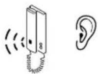
This symbol indicates an acoustic signal issued by a device should be observed. The length of the signal indicates the acknowledgement of settings.
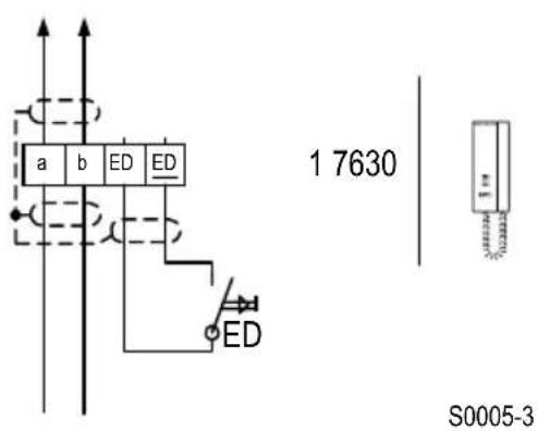
Circuit diagram symbols

This circuit diagram symbol indicates that the line screening sheaths must be connected across the joints.
List of abbreviations
ED Apartment button
TO Door opener
UV Subdistribution
Terminal designations
a Bus terminal
b Bus terminal
ED Apartment button
ED Apartment button
a1 Main bus line
a2 Main bus line
a3 Main bus line
Information on article numbers
The article numbers on the title page are made up of four components:
RTY Production ID
1 8411 Device number
20 Colour ID
01 Country code
In the following, only the device number is provided.
General Information
Cable networks
Existing lines can be used as bus lines. We recommend the following, commercially available lines:
- CAT 1 (for audio)
CAT3
Telecommunication line J-Y (St) Y
Telecommunication line J-2Y (z) Y with strain-relief - Telecommunication grounding cable, longitudinally and transversally waterproof
Cable layout
It is recommended to lay the bus line from subscriber to subscriber and to connect it to the connection terminal on the device.
All the line screening sheaths and free wires must be connected across the joints and laid to Terminal b on the TwinBus power supply unit. Please use appropriate locally provided terminals for this.
In order to fulfil the general safety requirements for telecommunication systems complying to VDE 0800 and prevent disturbances on the lines, ensure that the mains voltage and SELV (TwinBus line) are laid separately. A clearance of 10cm must be maintained for the installation. In the case of a common line cabling, a separating webbing must be inserted in the installation channels.
Bus lines a/b must not be terminated with terminal resistors.

Malfunctions due to strong magnetic fields
No other devices with strong magnetic fields (contactors, transformers, etc.) may be installed in the direct vicinity of the power supply unit and additional devices. Malfunctions could be caused by induced voltage peaks.
Maximum line lengths
The loop resistance of each TwinBus line must not exceed max. 20 Ohm. This results in the following maximum line lengths:
| Wire diameter in mm 0,8 0,6 | |
| Resistance in Ohm/m 0,0349 0,0621 | |
| Line lengths between TwinBus power supply unit 1 7573 and indoor telephone | 280 m 160 m |
| Line lengths between TwinBus power supply unit 1 7573 and door unit (lighting) | 60 m 30 m |
| Line lengths between TwinBus power supply unit 1 7573 and door openers up to 8 V/1 A | 50 m 30 m |
Considerations when renovating

Note:
In the case of existing YR cables, all the free wires on the TwinBus power supply unit must be laid as screening to a Terminal b.
Connection to the mains

Equipment damage through overvoltage or short circuiting
Equipment damage can occur through overvoltage or short circuiting. Connection must be made to a 230V ± 10% mains power outlet. The power must be fed via an intrinsic line safety switch with max.10 A.
Please note that a 230 V/AC power supply is required for the power supply units and mains transformers which are not explicitly depicted in the block diagrams.
Electrostatic charging

Risk of equipment damage through static electricity (ESD)
Static electricity could destroy equipment if direct contact is made with the printed circuit boards. Discharge electrostatic charges before touching the equipment.
Intended use
This door intercom is a system devised for controlling access and internal communication inside residential buildings.
Any other use is considered unintended use. The manufacturer is not deemed liable for any damage resulting from unintended use. The risk, in this case, is assumed solely by the installation technician.
Intended use also includes observing the manufacturer's regulations concerning use and maintenance. The system may only be installed and serviced by persons familiar with it and informed of the risks involved.
Cleaning
The surfaces of the TwinBus devices can become dirty due to environmental influences and frequent use. The surfaces should only be cleaned with a damp cloth and suitable, mild household cleaning agent.
Make certain that the plastic parts of the door station (e.g. name labels) do not come into contact with the cleaner.
Observe the information provided by the cleaning agent manufacturer.
Directives/conformity
All TwinBus devices have been constructed according to the following directives:
- EC Directive "Electromagnetic Compatibility" 89/336/EEC or 2004/108/EC (complying with the currently valid version).
- Directives on low-voltage 72/23/EEC (complying to the currently valid version).
TwinBus devices bear the CE approval label. Conformity has been certified. The corresponding documents are held by the manufacturer.
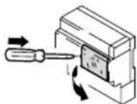
Risk to life from electric shock.
In the case of surface installation of the power supply units, the terminal cover must be attached on the 230V connection. De-energize the device before removing the terminal cover.

Damage to the device through environmental influences
The devices must not be mounted outside or in rooms exposed to damp.
Installation
Door intercom for one-family residence
Each residential unit can be accessed separately from the main entrance. The doorbell for the apartment door is connected directly to the indoor telephone. Incoming calls from the door station and the apartment door (ED) are automatically indicated by different ringing tones. The door opener (TO) at the main entrance can be actuated from all the indoor telephones.
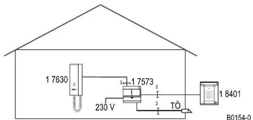
Block diagram: Door intercom for single or multi-family residence.
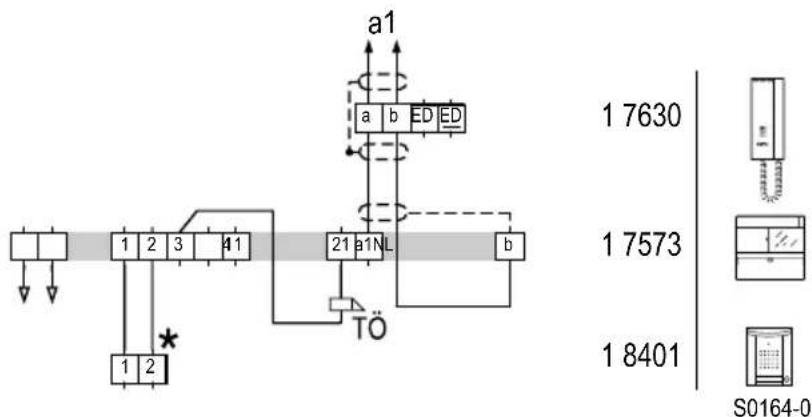
Circuit diagram: Door intercom for single or multi-family residence, including illumination
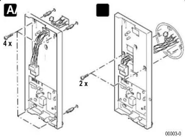
Assembly
Power supply unit
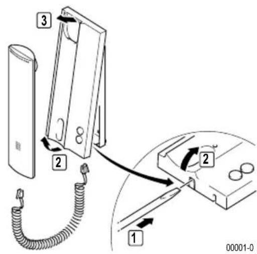
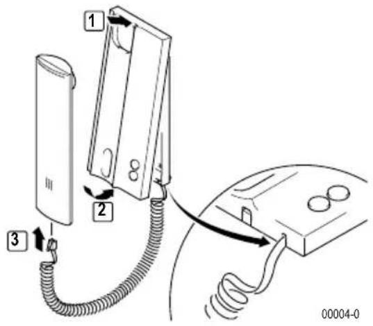
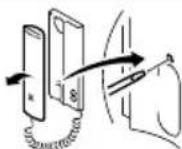
TwinBus indoor telephone 1 7630
The following section describes the assembly of the TwinBus indoor telephone 1 7630.
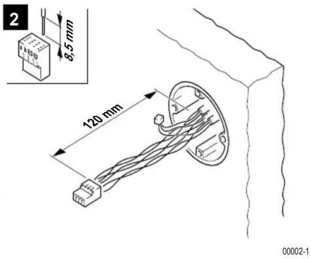
Connection
Assembly
Please provide your customers with a copy of the operating instructions for the TwinBus device.
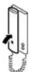
Surface-mounted
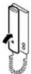
Please remove the clamp from the packaging.
1
3
4
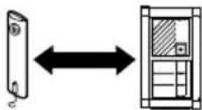
A Wall mounting
B Switch box mounting
Starting up
The system can be started using the indoor telephone.
In order to allow the operator to change the call tone of the main bell button, the main bell button must be programmed as the main button when initial setting takes place. The procedure must be repeated for other bell buttons.
The intercom can be used for start-up with two persons.
One-man start-up
Activity Result
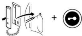
Press and hold for >5 s until flashes

Within one minute, press the button to be assigned on the door station
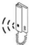
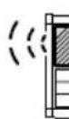

acoustic signal for confirmation at indoor telephone and door station
Two-man start-up
Activity Result

Press and hold for >5 s until flashes
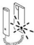

announce button to be assigned via voice connection
Within one minute, press the button to be assigned on the door station


acoustic signal for confirmation at indoor telephone and door station
Short tone: Device is ready for operation.
No tone: Time limit exceeded.
Long tone: Programming procedure failed.
If the time limit has been exceeded:
Repeat the procedure.
If the programming procedure failed:
Check on the TwinBus power supply unit whether the setting protection is activated - see page 27.
Delete settings
This function deletes all settings and programmed bell buttons. If necessary, please note any existing customer settings before deletion.
Activity Result
Press and hold for 5 s until Acoustic signal for confirmation
Short tone: Settings have been deleted.
© Long tone: Settings have not been deleted.
If the settings have not been deleted:
Check on the TwinBus power supply unit whether the setting protection is activated - see page 27.
Repeat the procedure.
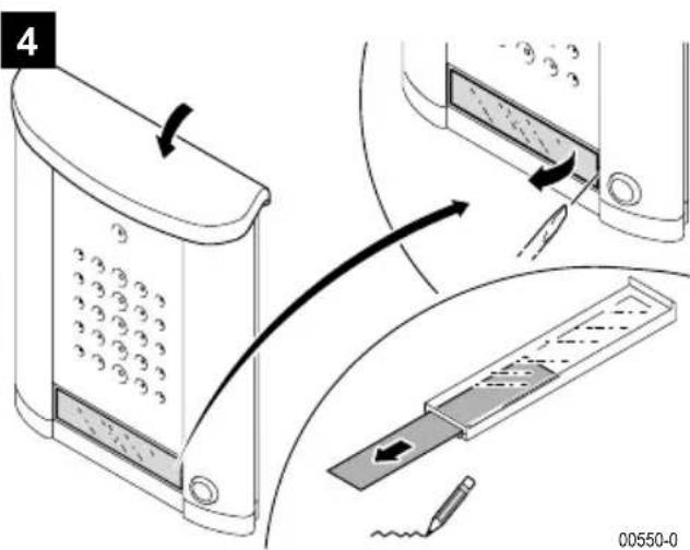
Entravox door station
Assembly
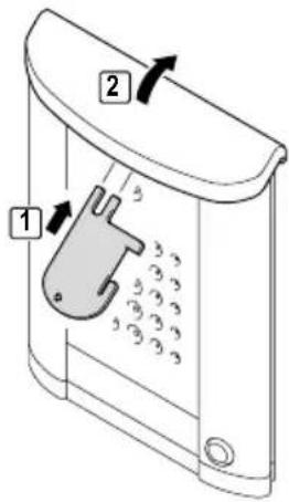
1
00547-0
2
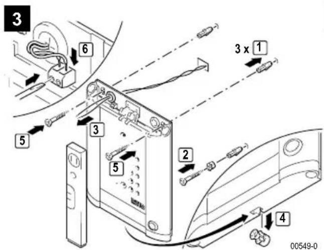
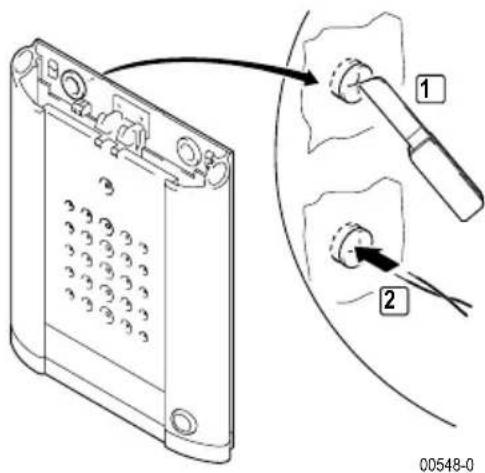
Connection
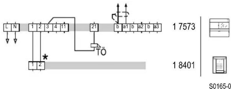
Circuit diagram: Connection of the door unit
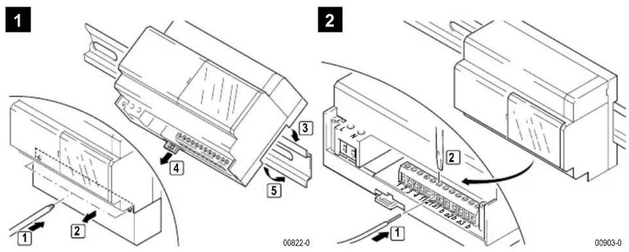
TwinBus power supply unit 1 7573
Device description
The power supply provides the power for the devices attached to the TwinBus. It controls the door station and provides functions that the connected subscribers can use.
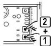
Connections
L, N 230 V mains connection
1, 2, 3, 4 Door station, polarized
3, 21 Operate
11, b external control for door opening relay
a1, b Main bus line 1
a2, b Main bus line 2
a3, b Main bus line 3
System bus for supplying additional devices
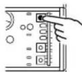
Adjust door opening time
The door opening time can be set within a range of 1 to 120 seconds. The factory setting of the running time is 3 seconds.
Activity Result
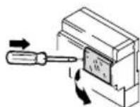
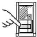
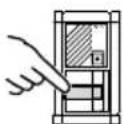
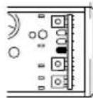
Open plexiglass cover on power supply unit 17573
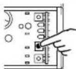
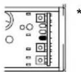
Press and hold "Z" LD 1 (yellow) flashes
*1 flash = 1 s
Further information on the power supply unit is available in the Chapter "Service" - refer to Page 28.
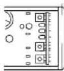
Delete settings
Activity Result
Press "P" and then "Z" for >5 s until LD 1 briefly illuminates yellow
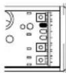
Activating/deactivating adjustment protection
Activity Result
Open plexiglass cover on power supply unit 17573
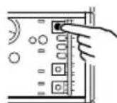
Press "prog. protection" until LD 3 is lit green ON
Press "prog. protection" until LD 3 (green) goes out OFF

Note:
Adjustment protection remains in effect after activation on the TwinBus power supply unit 1 7573 in indoor telephones even if electrical power is turned off to the indoor telephone.
Service
Measuring points
TwinBus power supply unit 1 7573
| Clamp Load Target voltage |
| a1 b open/switched 24 V DC to 30 V DC |
| a2 b open/switched 24 V DC to 30 V DC |
| a3 b open/switched 24 V DC to 30 V DC |
| 1 b no door communication 0 V DC |
| 1 b with door communication 24 V DC |
| 2 b no door communication 30 V DC |
| 2 b with door communication 0 V DC |
| 3 4 without load 11 V AC |
TwinBus indoor telephone
| Clamp Target voltage | |
| a b 20 V DC to 28 V DC | |
| ED ED | 20 V DC to 28 V DC |
Thermal fuses
The power supply unit 1 7573 has two electronic fuses, instead of conventional fuses, which interrupt the respective power circuit in the case of an overload.
If one of these fuses is tripped, the associated voltage indicator LED in the power supply unit goes off. Proceed as follows to switch on again:
Switch mains voltage off and leave off for approximately 1 minute.
Remedy short circuit or overload.
Switch mains power supply on again.
The associated voltage indicator LED in the power supply unit is lit again.
Service indicators
TwinBus power supply unit 1 7573
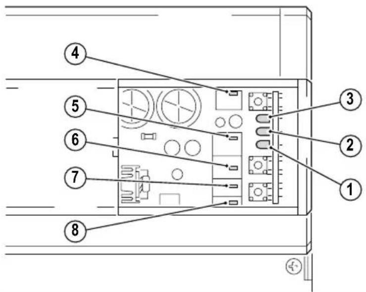
Indicator Meaning
LED 1 (yellow) flashes The door opener operating time is set (LED flashes every second when door opening time is being set) or the mode used for programming switching commands is active.
LED 2 (red) is lit Indicates transmission of bus commands, e.g.:
- handset has been picked up or replaced.
Doorbell is pressed. - Door opener or button operation.
- Internal call or switching command will be initiated.
LED 2 (red) flashes Start-up has been activated via the apartment button.
LED 3 (green) illuminates - Adjustment protection is activated.
LED 4 (red) illuminates Overload or short circuit on the system bus.
LED 5 (green) illuminates Door communication is activated
LED 6 (yellow) illuminates - Direct current indicator (bus voltage)
LED 7 (yellow) illuminates - Alternating current indicator (door opener)
LED 8 (red) illuminates Door opener relay has switched.
Avant de continuer ...
Directives/Conformité
- 1 x clignotement = 1 sec.