HCEC2600FD4 - Dashcam ALPINE - Free user manual and instructions
Find the device manual for free HCEC2600FD4 ALPINE in PDF.
User questions about HCEC2600FD4 ALPINE
0 question about this device. Answer the ones you know or ask your own.
Ask a new question about this device
Download the instructions for your Dashcam in PDF format for free! Find your manual HCEC2600FD4 - ALPINE and take your electronic device back in hand. On this page are published all the documents necessary for the use of your device. HCEC2600FD4 by ALPINE.
USER MANUAL HCEC2600FD4 ALPINE
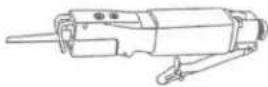
HCE-C2600FD4/HCE-2100RD4
Smittybilt XRC Gen 2 bumpers and Universal bumper installation
Installation Manual
Introduction
- Congratulations on purchasing the HCE-C2600FD4/HCE2100RD4. This installation manual is designed to take you through the step-by-step installation of the HCE-C2600FD4/HCE2100RD4. Please familiarize yourself with the owner's manual and if you still have additional questions please call 1-800-TECH-101.
Note
- Design and specifications are subject to change without notice for improvement.
To Ensure Safe Use Always Follow These Precautions
- The installation of this product requires specialized skills and experience. We recommend that you have the product installed by an Alpine authorized dealer.
- Before you use this product, be sure to carefully read this installation manual and the separate user's manual so that you can use the product correctly. Alpine Electronics bears no responsibility for problems that arise as a result of failure to follow the instructions in the manuals.
- This manual includes a number of symbols that are intended to help you use the product safely, to prevent harm to you and others, and to protect against damage to property. These symbols and their meanings are listed below. Make sure you fully understand these symbols before you begin reading the main text.
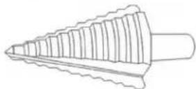
Tools Required
| Step Drill | Air Reciprocating Saw | #2 Hex Screwdriver |
 |  |  |
| Countersink Drill Bit | Cordless Power Drill | 3/16” Drill bit |
 |  |  |
Accessory List
| Camera Bracket | 8-32 x 1⁄2 Flat Socked Head Cap Screws | Decal Guide |
 | 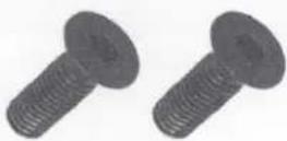 |  |
| Other parts and instruction are described on the HCE-C2600FD / HCE-C2100RD Owners Manual | ||
HCE-C2600FD / HCE-C2100RD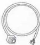      x4x4 x4x4 | ||
HCE-C2100RD    x5 x5 | HCE-C2600FD x5 x5 | |
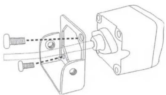
Mounting the camera to the bracket
1 Attach the camera to the swivel bracket attachment using the (2) Phillips screws provided.
natural_image
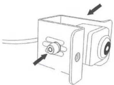
Technical line drawing of a mechanical assembly with bolts and housing (no text or symbols)2 Attach the camera to the bumper bracket using the (2) Hex screws.
natural_image
Technical line drawing of a mechanical component with arrows indicating assembly or movement (no text or symbols)XRC Bumper installation
1 Remove (6) Hex Screws from the bumper plastic cover.
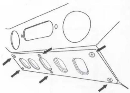
natural_image
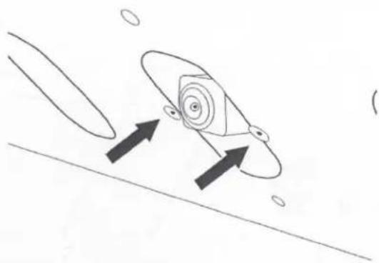
Technical line drawing of a mechanical component with multiple oval features and directional arrows indicating movement (no text or symbols)2 Adjust the camera's depth and mount the camera to the XRC bumper using the (2) Flat socket head cap screws provided.
natural_image
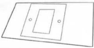
Simple line drawing of a rocket with two upward arrows indicating motion, no text or symbols presentUniversal Mount Cutout Instructions
1 Place the decal guide on the desired camera location.

natural_image
Simple geometric diagram with two parallel lines and a nested square frame (no text or symbols)2 Use a 3/16" drill bit to create (2) screw mounting holes on the bumper.
natural_image
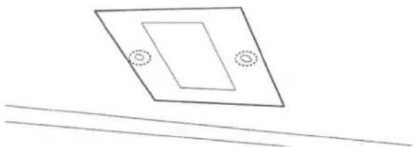
Simple line drawing of a tilted rectangular plate with two circular holes, above two parallel lines (no text or symbols)3 Use a step drill to make (4) openings on the camera opening area.
natural_image
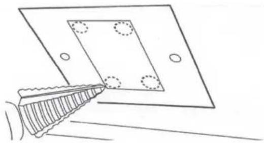
Line drawing of a hand holding a tool near a square plate with four circular holes (no text or symbols)4 Use a reciprocating saw to cut the camera opening.
natural_image
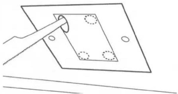
Simple line drawing of a hand using a tool to cut a square plate with holes, no text or symbols present.5 Use a metal countersink bit to flush the flathead screws on to the bumper.
6 Use the (2) Flathead Hex screws to mount the camera.

natural_image
Simple line drawing of a device and two circular objects (no text or symbols)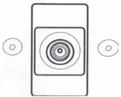
natural_image
Simple diagram with concentric circles and two small hexagons, no text or symbols presentALPINE®
HCE-C2100RD
HDR REAR VIEW CAMERA
HCE-C2600FD
HDR FRONT VIEW CAMERA
- OWNER'S MANUAL
Please read before using this equipment.
• MODE D'EMPLOI
Victoria 3803, Australia
Phone 03-8787-1200
ALPINE ELECTRONICS GmbH
Wilhelm-Wagenfeld-Str. 1-3, 80807 München, Germany
Phone 089-32 42 640
ALPINE ELECTRONICS OF U.K. LTD.
Alpine House
Fletchamstead Highway, Coventry CV4 9TW, U.K.
www.alpine.co.uk
ALPINE ELECTRONICS France S.A.R.L.
Designed by ALPINE Europe
Printed in Korea
68M17170K46-0
Thank you for purchasing this Alpine product. Please take a moment to protect your purchase by registering your product now at the following address: www.alpine-usa.com/registration.
You will be informed of product and software updates (if applicable), special promotions, news about Alpine, and entered for a chance to win prizes.
www.alpine-usa.com/registration.
Operating Instructions
English

WARNING
This symbol means important instructions. Failure to heed them can result in serious injury or death.
WHEN USING A CAMERA SYSTEM, THE DRIVER MUST VISUALLY CHECK ACTUAL CONDITIONS AROUND THE VEHICLE. MAKE SURE THERE ARE NO PERSONS OR ANIMALS IN THE AREA IN WHICH YOU ARE MANOEUVRING OTHERWISE YOU COULD INJURE THEM.
A camera assists the driver by sending images to the screen showing conditions in view of the camera. The camera uses a wide-angle lens. Therefore, there is a difference in distance perspective between what is normally seen and what appears on the screen. Also, the images shown by the rearview camera are reversed, so as to appear the same as what is seen through the rearview mirror.
The camera may not perform to full capability due to variables such as:
- weather conditions such as hard rain, snow, fog or mud
• extremely high or low temperatures near camera
• slope of vehicle and/or roadway - direct exposure to very bright light such as headlamp or bright sunlight
- moving from very dark to very bright light and vice versa such as in parking garages or tunnels
• extremely low light areas - walls or objects that are located diagonally in relation to the camera
• retracted mirrors that change camera viewing angle
• open doors or trunks
• changes to height of vehicle due to loading capacity or hydraulic suspensions
• obstacles located at the corner of the vehicle
DO NOT DISASSEMBLE OR ALTER.
Doing so may result in an accident, fire or electric shock.
KEEP SMALL OBJECTS SUCH AS BOLTS OR SCREWS OUT OF THE REACH OF CHILDREN.
Swallowing them may result in serious injury. If swallowed consult a Doctor immediately.
USE THE CORRECT AMPERE RATING WHEN REPLACING FUSES.
Failure to do so may result in fire or electric shock.
USE ONLY IN CARS WITH A 12 VOLT NEGATIVE GROUND.
(Check with your dealer if you are not sure.) Failure to do so may result in fire, etc.
BEFORE WIRING, DISCONNECT THE CABLE FROM THE NEGATIVE BATTERY TERMINAL.
Failure to do so may result in electric shock or injury due to electrical shorts.
DO NOT USE BOLTS OR NUTS IN THE BRAKE OR STEERING SYSTEMS TO MAKE GROUND CONNECTIONS.
Bolts or nuts used for the brake or steering systems (or any other safety-related system), or tanks should NEVER be used for installations or ground connections. Using such parts could disable control of the vehicle and cause fire etc.
DO NOT DAMAGE PIPE OR WIRING WHEN DRILLING HOLES.
When drilling holes in the chassis for installation, take precautions so as not to contact, damage or obstruct pipes, fuel lines, tanks or electrical wiring. Failure to take such precautions may result in fire.
MINIMISE DISPLAY VIEWING WHILE DRIVING.
Viewing the display may distract the driver from looking ahead of the vehicle and cause an accident.
DO NOT SPLICE INTO ELECTRICAL CABLES.
Never cut away cable insulation to supply power to other equipment. Doing so will exceed the current carrying capacity of the wire and result in fire or electric shock.
DO NOT INSTALL IN LOCATIONS WHICH MIGHT HINDER VEHICLE OPERATION, SUCH AS THE STEERING WHEEL OR GEAR LEVER.
Doing so may obstruct forward vision or hamper movement etc. and results in serious accident.
DO NOT ALLOW CABLES TO BECOME ENTANGLED IN SURROUNDING OBJECTS.
Arrange wiring and cables in compliance with the manual to prevent obstructions when driving. Cables or wiring that obstruct or hang up on places such as the steering wheel, gear lever, brake pedals, etc. can be extremely hazardous.
DO NOT ROUTE ELECTRICAL CABLES NEAR HOT OR MOVING PARTS
Route the cables and wiring away from hot or moving parts, and fix them securely to avoid heat/mechanical damage to the cable insulation, which may result in shortcircuit, fire or electric shock.
MAKE THE CORRECT CONNECTIONS.
When making connections to the vehicle's electrical system, be aware of the factory installed components (e.g. on-board computer). Do not tap into these leads to provide power for this unit. When connecting the device to the fuse box, make sure the fuse for the intended circuit of the device has the appropriate amperage. Failure to do so may result in fire or damage to the unit and/or the vehicle. When in doubt, consult your Alpine dealer.
USE THIS PRODUCT FOR MOBILE 12 VOLT APPLICATIONS.
Use for other than its designed application may result in fire, electric shock or other injury.
CHECK THAT THE CAMERA MOUNTINGS IS ATTACHED SECURELY, AND THAT THE SCREWS ARE TIGHT BEFORE DRIVING.
Failure to do so may result in an accident.
WHEN INSTALLING OR CHECKING A CAMERA, DO SO AFTER PARKING THE CAR IN A LEVEL, SAFE PLACE, TURNING OFF THE ENGINE, AND APPLYING THE HAND BRAKE.
Failure to do so may result in an accident.
WHEN USING A DRILL TO MAKE A HOLE, TAKE PRECAUTIONS SUCH AS WEARING GOGGLES SO FRAGMENTS DO NOT GET INTO THE EYES.
Failure to do so may result in injury.

CAUTION
This symbol means important instructions. Failure to heed them can result in injury or material property damage.
HAVE THE WIRING AND INSTALLATION DONE BY EXPERTS.
The wiring and installation of this unit requires special technical skill and experience. To ensure safety, always contact the dealer where you purchased this product to have the work done.
ARRANGE THE WIRING SO IT IS NOT CRIMPED OR PINCHED BY A SHARP METAL EDGE.
Route the cables and wiring away from moving parts (like the seat rails) or sharp or pointed edges. This will prevent crimping and damage to the wiring.
USE SPECIFIED ACCESSORY PARTS AND INSTALL THEM SECURELY.
Be sure to use only the specified accessory parts. Use of other than designated parts may damage this unit internally or may not securely install the unit in place. This may cause parts to become loose resulting in hazards or product failure.
CONNECT LEADS PROPERLY
Be sure to connect the colour coded leads according to the diagram. Incorrect connections may cause the unit to malfunction or cause damage to the vehicle's electrical system.
HALT USE IMMEDIATELY IF A PROBLEM APPEARS.
Failure to do so may cause personal injury or damage to the product. Return it to your authorized Alpine dealer or the nearest Alpine Service Center for repairing.
EXCEPT FOR THE CAMERA, DO NOT ATTACH ANY PARTS TO AREAS WHICH WILL GET WET, OR WHERE THERE IS A LOT OF HUMIDITY OR DUST.
Failure to do so may result in fire or damage.
DO NOT ATTACH THE CAMERA TO FLUOROCARBON RESIN FINISHED CAR BODIES OR GLASS.
Doing so reduces the strength of the camera's mounting. This could cause it to fall off and cause injury or damage to the car's body.
DO NOT ATTACH THE CAMERA TO ANY SURFACE WHERE THE ENTIRE ADHESIVE SURFACE CANNOT BE APPLIED.
Doing so reduces the strength of the camera's mounting. This could cause it to fall off and cause injury or damage to the car's body.
NOTICE
• About Care of Device
Do not assert any excess pressure to the camera or the mounting, as this could cause the camera direction to shift, or the camera mounting bracket to come off.
- To prevent the camera lens, mounting and cords from changing colour or shape, or from deteriorating, wipe with a chemical-free, damp cloth.
- Do not use an automatic car wash or high-pressure washer. Doing so could cause the camera to come off, damage to the device cord, or may allow water to enter the camera or the inside of the car.
- In some cases, to attach the device, a hole must be drilled in the car body, requiring use of touch-up paint (retail product) for rust-prevention, and should be prepared beforehand.
- Be sure to disconnect the cable from the (−) battery post before installing your HCE-C2100RD/HCE-C2600FD. This will reduce any chance of damage to the unit in case of a short-circuit.
- Be sure to connect the colour coded leads according to the diagram. Incorrect connections may cause the unit to malfunction or damage to the vehicles electrical system.
- When making connections to the vehicles electrical system, be aware of the factory installed components (e.g. on-board computer). Do not tap into these leads to provide power for this unit. When connecting the HCE-C2100RD/HCE-C2600FD to the fuse box, make sure the fuse for the intended circuit of the HCE-C2100RD/HCE-C2600FD has the appropriate amperage. Failure to do so may result in damage to the unit and/or the vehicle. When in doubt, consult your Alpine dealer.
- About Rear Camera
The rear camera is optimized for use in this system, as a dedicated product, it should not be used in other systems.
• About Power Connection
Connect the reverse input wire (orange/white) to the power wire of the reverse lamp. Consult your Alpine dealer for details. Confirm that this connection is made to the negative side of the reverse lamp.
- Do not use mobile phones and wireless devices near the camera.
Doing so may result in noise on the screen or malfunction. It is recommended to use mobile phones or wireless devices away from the camera.
• About Camera Installation Location
Before installing, make sure there is a enough space to be able to install the camera. If possible, install the camera in the center of the bumper. If the camera is installed off-center, the image may differ from the actual view. Calibration is necessary.
• Confirming the Display Function
To connect the unit, confirm that the monitor will require a compatible RCA pin jack.
English
- REAR VIEW CAMERA (HCE-C2100RD) is designed for use with Alpine AV head units or navigation systems with touchscreen operation.
Français
1 Place the vehicle's transmission into reverse. The video images behind the vehicle and its surroundings are displayed while in reverse.
2 Shifting out of reverse returns the display to whatever was being shown before backing up.
• Refer also to the Owner's Manual of the connected monitor/navigation system.
- Be sure to also check behind and around the car visually. Use the camera image to assist in showing conditions behind and around the car.
- Depending on where the unit is installed, actual conditions may differ from the displayed image.
Français
1 Touch the screen while the camera image is displayed.
2 Touch [Back], [Panorama], [Corner] or [Top] to choose the viewing angle.
[Back]: Rear View
Displays an image of the area behind the vehicle. Use this when backing into a parking space.
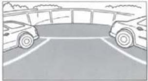
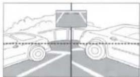
[Panorama]: Panorama View
Displays a general perspective of what is behind the car. Use this when you want to check mainly behind the car.
[Top]: Ground View
Displays an image from above down to the lower section of the car. Use this when to determine the car's position in relation to the curb, etc.
[Corner]: Corner View
Displays a divided image left and right of centre. Use this mainly when checking the left and right directional view.
Français
natural_image
Plain pavement with two rectangular white bars on the left side (no text or symbols)Panorama View /Vue
panoramique /Visión panorámica
natural_image
Illustration of two cars parked in a parking lot with adjacent buildings (no text or symbols visible)natural_image
Simple diagram of a rectangular object with two horizontal bars and a central cross-shaped element, surrounded by vertical white lines (no text or symbols)natural_image
Two cars parked in front of a road with a vehicle lane marked by a sign (no text or symbols on the cars or road)Installation /Installation /Instalación
natural_image
Simple line drawing of a kitchen sink with a handle and lid, no text or symbols presentFig. 1 / Schéma 1 / Fig. 1
text_image
② ④ (Both sides)/ (deux côtés)/ (Ambos lados)Fig. 2 / Schéma 2 / Fig. 2
text_image
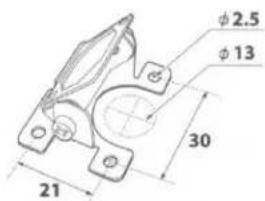
φ2.5 φ13 30 21Fig. 3 / Schéma 3 / Fig. 3
English
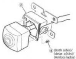
1 Attach the mounting bracket to the camera mounting stage with the angle adjustment screw as shown in the figure.
2 Attach the camera to the camera mounting bracket ②. Pull the camera cable through to the camera mounting bracket ②, and secure with the Camera mounting screws ③ (see Fig. 2).
3 Loosen the camera mounting bracket ② and angle adjustment screw. Determine the mounting angle, and carefully tighten the angle adjustment screw.
4 Make a 13 mm hole in the surface where the camera is mounted (see Fig. 3).
5 Pull the camera cable inside the car through the hole made in step 3.
6 Peel off the adhesive seal from the camera mounting bracket and attach the camera mounting bracket on the chassis of the vehicle. If required, fix the camera mounting bracket using self-tapping screws.
- Attach the camera in a position where it does not touch the number plate.
- Use retail touch-up paint to paint the surface and surrounding area when a hole has been made in a metal surface.
- Make sure water cannot enter the hole made for the camera cable. Use commercially available waterproof tape or sealant.
- If necessary, use a self-tapping screw ⑨ to fix the camera mounting bracket (In the case of a plastic mount area).
Français
text_image
Technical diagram showing car interior components with numbered annotations and assembly stepsFig. 4 / Schéma 4 / Fig. 4
① Rearview camera /Caméra de recul /Cámara de marcha atrás
⑥ Waterproofing pad /Protège câble étanche /Dispositivo protector resistente al agua
⑧ Wire clamp / Attache fils / Fijador de cables
(A) To HCE-C2100RD-compatible product /Vers le produit compatible avec HCE-C2100RD /Al producto compatible con el HCE-C2100RD
English Français Español
1 Secure the camera cable while referring to Fig. 4. Attach the waterproofing pad ⑤ with the waterproofing pad adhesive sheet ⑥, and secure any slack cable around the waterproofing pad ⑤ using the wire clamp ⑧.
- Ensure the cable does not get caught in the trunk, rear door(s) or any hinges.
- The cable should go on the outside of car hinges and harness covers.
• After completing wiring, open and close the trunk and the rear doors several times to confirm the cable is not getting caught or rubbing anywhere.
(HCE-C2600FD is inapplicable./HCE-C2600FD est inapplicable./HCE-C2600FD no es aplicable.)
flowchart
graph TD
    A["Front of pickup truck*/ Avant du pickup*/ Parte delantera de la camioneta*"] --> B["Recommended camera power supply mounting location (inside pickup cab)/ Emplacement de montage recommandé de l'alimentation de la caméra (à l'intérieur de la cabine du pickup)/ Ubicación recomendada para colocar la fuente de alimentación de la cámara (en el interior de la camioneta)"]
    B --> C["Central component a"]
    B --> D["Central component b"]
    B --> E["Central component c"]
    B --> F["Central component d"]
    style A fill:#f9f,stroke:#333
    style B fill:#ccf,stroke:#333
    style C fill:#cfc,stroke:#333
    style D fill:#fcc,stroke:#333
    style E fill:#cff,stroke:#333
    style F fill:#ffc,stroke:#333
text_image
(D) (C) (A) (D)Fig.15/Schéma 15/Fig.15
English
Français
Español
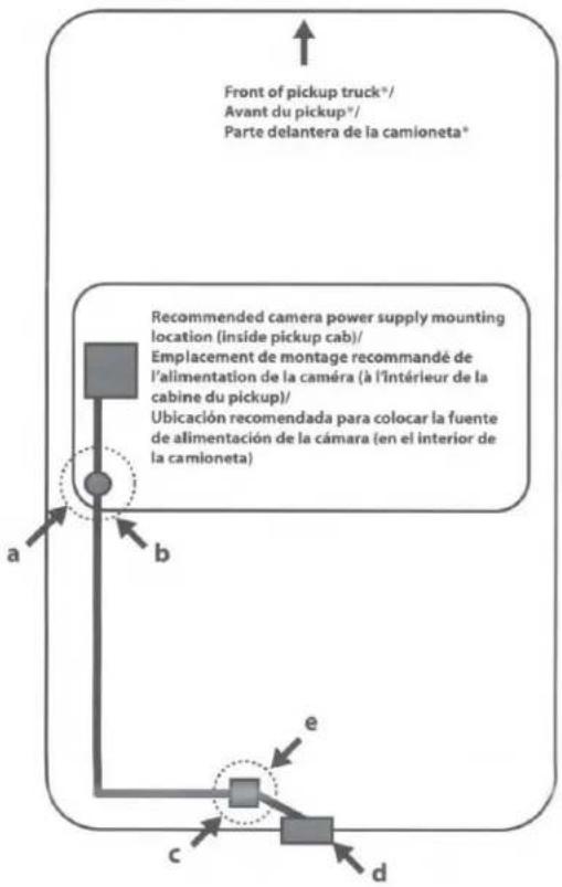
a: Rubber grommet to pass camera wire from inside of pickup truck cab to underside of pickup truck chassis.
b: In pickup truck* installations, the wire that connects between the camera and the camera power supply typically gets installed under the pickup truck chassis.
- This wire must be protected from damage using split-loom tubing in any areas where it is installed under the pickup chassis.
- The rubber grommet where the wire passes from the cab to the underside of the truck must be sealed with silicone to prevent moisture intrusion into the pickup truck cab.
c: White connector between rearview camera and power supply.
d: Recommended HCE-C2100RD rearview camera mounting location (on rear bumper).
e: In pickup truck installations, the white electrical connector between the rearview camera and the camera's power supply may be exposed to moisture. If so, it must be sealed to prevent corrosion.
Perform waterproofing with the provided heat-shrink tube by following the procedure below:
1 Preparation -Fig.13
(1) Insert the heat-shrink tube ⑩ over the camera extension cable ⑦.
(2) Connect the camera cable ① to the connector of the camera extension cable ⑦.
(3) Install the heat-shrink tube ⑩ so tube (A) is covered (with approx. 0.5 inch).
2 Waterproofing -Fig.14
When preparation is complete, straighten the cable, and shrink the heat-shrink tube by heating it from side (B) with a heat gun.
3 Check -Fig.15
Ensure that connectors (A) and (C) is entirely covered with the heat-shrink tube ⑩
When the heat-shrink tube is at its smallest, epoxy or caulk should be flowed onto the (D) sections to complete the waterproofing process.
Caution
- Be careful not to melt the camera cable or camera extension cable by the heat gun.
- Be careful not to burn yourself during this procedure.
• After waterproofing is complete, do not bend the cord forcibly.
- FRONT VIEW CAMERA (HCE-C2600FD) is designed for use with Alpine AV head units or navigation systems with touchscreen operation.
Français
1 Touch the screen while the camera image is displayed.
2 Touch [Panorama], [Corner] or [Top] to choose the viewing angle.
[Panorama]: Panorama View:
Displays a general perspective of what is ahead of the car. Use this when you want to check mainly ahead of the car.
[Corner]: Corner View:
Displays a divided image left and right of centre. Use this mainly when checking left and right directional view.
[Top]: Ground View:
Displays an image from above down to the lower section of the car. Use this when to determine the car's position in relation to the curb, etc.
Français
natural_image
Simple line drawing of a crosswalk with trees and a vehicle in the background (no text or symbols)natural_image
Simple line drawing of a crosswalk with trees and hills (no text or symbols)natural_image
Abstract grayscale pattern with three vertical white bars on a gray background (no text or symbols)Installation /Installation /Instalación
natural_image
Line drawing of a car's front bumper and rear wheel (no text or symbols)text_image
Diagram showing car wheel assembly with labeled parts A, B, C and directional arrows indicating rotation or movementFig. 11/Schéma 11/Fig. 11
English
1 Attach the mounting bracket to the camera mounting stage with the special screw for angle adjustment using the supplied hex wrench as shown in the figure.
2 Attach the camera to the camera mounting bracket ③. Pull the camera cable through to the camera mounting bracket ③, and secure with the Camera mounting screws ④ (see Fig. 9).
3 Loosen the camera mounting bracket ③ and angle adjustment screw. Determine the mounting angle, and carefully tighten the angle adjustment screw.
4 Make a 13 mm hole in the surface where the camera is mounted (see Fig. 10).
5 Pull the camera cable inside the car through the hole made in step 3.
6 Peel off the adhesive seal from the camera mounting bracket and attach the camera mounting bracket on the chassis of the vehicle. If required, fix the camera mounting bracket using self-tapping screws.
7 Connect the camera cable through the service hole to the power box (see Fig. 11).
A: Service hole
B: Grommet
C: Make an incision in the grommet.
- Attach the camera in a position where it does not touch the number plate.
- Use retail touch-up paint to paint the surface and surrounding area when a hole has been made in a metal surface.
- If necessary, use a self-tapping screw ⑦ to fix the camera mounting bracket (In the case of a plastic mount area).
- Route all cables away from hot areas/parts of the car.
Français
- For details on connection, refer to the installation manual of the HCE-C2100RD-compatible product.
* Connect the water-proof connector for the camera and camera extension cable securely. When disconnecting the water-proof connector, use a flat-blade screwdriver. - REAR VIEW CAMERA (HCE-C2100RD) is designed for use with Alpine AV head units or navigation systems (INE-W710D, etc.). with touch-screen operation. If you connect the HCE-C2100RD to a product without a touch-screen display, the FRONT VIEW CAMERA (HCE-C2600FD) (sold separately) is required. For information on HCE-C2100RD-compatible products, contact your local authorized Alpine dealer or visit the Alpine Website.
Français
- For further details on the camera angle adjustment, refer to "Adjusting the Camera Angle (HCE-C2100RD and HCE-C2600FD)" of these Operating Instructions.
Français
text_image
180° 125°Fig. 13 / Schéma 13 / Fig. 13
natural_image
Diagram showing a vehicle passing through a road with a sensor or detection device above (no text or symbols present)Fig. 14 / Schéma 14 / Fig. 14
English
Français
Español
Caution
When adjusting the camera angle, do so after turning off the engine and applying the hand brake to avoid an accident.
1 Put the gear shift into reverse (R) or press ON/OFF, and check the image from the camera on the display.
When you set the corner view, adjust the angle so that the road may be roughly viewed horizontally (Fig. 14).
2 Loosen the camera mounting bracket ② and angle adjustment screw. Determine the viewing angle, and carefully tighten the angle adjustment screw.
Attention
The Ground Truth image displays a single, solid horizontal line. According to Rule 2 (UNDERSCORE & LINE RULES), this is a stylistic or background line, not a placeholder underscore. Therefore, the OCR result must ignore it and output nothing or only meaningful text. The provided OCR content is "____", which consists of four underscores. This is an incorrect interpretation of the line as a placeholder, violating the rule that stylistic lines must be ignored. The OCR has hallucinated underscores where none should exist based on the GT's visual context. Hence, the OCR result is inconsistent with the Ground Truth.

English
Français
Español
Information on Disposal of Old Electrical and Electronic Equipment and Battery (applicable for countries that have adopted separate waste collection systems) If you want to dispose this product, do not mix it with general household waste. There is a separate collection system for used electronic products in accordance with legislation that requires proper treatment, recovery and recycling. Contact your local authority for details in locating a recycle facility nearest to you. Proper recycling and waste disposal will help conserve resources whilst preventing detrimental effects on our health and the environment.
| HCE-C2600FD | HCE-C2100RD | |
| Power Requirements | 6.0V DC (5.0 to 9.0VDC allowable) | 6.0V DC (5.0 to 9.0VDC allowable) |
| Ground Type | Negative ground type | Negative ground type |
| Max. Power Consumption | 1.2W (6.0V) | 1.2W (6.0V) |
| Output Image | Normal image, CVBS (NTSC video signal) Image output for 16:9 wide-screen | Mirror image, CVBS (NTSC video signal)Image output for 16:9 wide-screen |
| Image Output Impedance | 75Ω (1vp-p) | 75Ω (1vp-p) |
| Image Sensor | 1/4 inch CMOS image sensor, aspect ratio 4:3 | 1/4 inch CMOS image sensor, aspect ratio 4:3 |
| Effective Number of Pixels | 1280 (horizontal)×960 (vertical)approximately 1.2 Mega pixels | 1280 (horizontal)×960 (vertical)approximately 1.2 Mega pixels |
| Lens Section | Focal length f=1.27mm, brightness F=1.8 | Focal length f=1.27mm, brightness F=1.8 |
| Angle of Field | Approximately 180° horizontally,approximately 70° vertically | Approximately 180° horizontally,approximately 125° vertically |
| Automatic image Adjusting Function | Automatic exposure adjustment, automatic white balance adjustment | Automatic exposure adjustment, automatic white balance adjustment |
| Synchronization System | Internal synchronization | Internal synchronization |
| Luminance S/N | 8.41 Lx | 8.41 Lx |
| Resolution (horizontal) | 330 TV lines or more (center area) | 330 TV lines or more (center area) |
| Illumination Rangellumination Range | Approximately 1.5Lx to 100kLx | Approximately 1.5Lx to 100kLx |
| Operating Temperature Range | Camera section: -22 to +158F (-30 to +70°C) | Camera section: -22 to +158F (-30 to +70°C) |
| Water Resistance | IP68 | IP68 |
| External dimensions (W×H×D) | Camera section: 23.6×23.6×26.1mm (excluding projection on the rear) | Camera section: 23.6×23.6×26.1mm(excluding projection on the rear) |
| Weight | Camera section: 41g (including cable but not including bracket and screw) | Camera section: 32g (including cable but not including bracket and screw) |
LIMITED WARRANTY
ALPINE ELECTRONICS OF AMERICA, INC. ("Alpine"), is dedicated to quality craftsmanship and is pleased to offer this Warranty. We suggest that you read it thoroughly. Should you have any questions, please contact your Dealer or contact Alpine at one of the telephone numbers listed below.
● PRODUCTS COVERED:
This Warranty covers Car Audio Products and Related Accessories ("the product"). Products purchased in the Canada are covered only in the Canada. Products purchased in the U.S.A. are covered only in the U.S.A.
● LENGTH OF WARRANTY:
This Warranty is in effect for one year from the date of the first consumer purchase.
● WHO IS COVERED:
This Warranty only covers the original purchaser of the product, who must reside in the United States, Puerto Rico or Canada.
WHAT IS COVERED:
This Warranty covers defects in materials or workmanship (parts and labor) in the product.
WHAT IS NOT COVERED:
This Warranty does not cover the following:
① Damage occurring during shipment of the product to Alpine for repair (claims must be presented to the carrier).
② Damage caused by accident or abuse, including burned voice coils caused by over-driving the speaker (amplifier level is turned up and driven into distortion or clipping). Speaker mechanical failure (e.g. punctures, tears or rips). Cracked or damaged LCD panels. Dropped or damaged hard drives.
③ Damage caused by negligence, misuse, improper operation or failure to follow instructions contained in the Owner's manual.
④ Damage caused by act of God, including without limitation, earthquake, fire, flood, storms or other acts of nature. Any cost or expense related to the removal or reinstallation of the product.
⑤ Service performed by an unauthorized person, company or association.
⑥ Any product which has the serial number defaced, altered or removed.
⑦ Any product which has been adjusted, altered or modified without Alpine's consent.
⑧ Any product not distributed by Alpine within the United States, Puerto Rico or Canada.
⑨ Any product not purchased from an Authorized Alpine Dealer.
● HOW TO OBTAIN WARRANTY SERVICE:
① You are responsible for delivery of the product to an Authorized Alpine Service Center or Alpine for repair and for payment of any initial shipping charges. Alpine will, at its option, repair or replace the product with a new or reconditioned product without charge. If the repairs are covered by the warranty, and if the product was shipped to an Authorized Alpine Service Center or Alpine, Alpine will pay the return shipping charges.
② You should provide a detailed description of the problem(s) for which service is required.
③ You must supply proof of your purchase of the product.
④ You must package the product securely to avoid damage during shipment. To prevent lost packages it is recommended to use a carrier that provides a tracking service.
ALPINE ELECTRONICS OF AMERICA, INC., 19145 Gramercy Place, Torrance, California 90501, U.S.A.
Do not send products to these addresses.
Call the toll free telephone number or visit the website to locate a service center.
● HOW WE LIMIT IMPLIED WARRANTIES:
ANY IMPLIED WARRANTIES INCLUDING FITNESS FOR USE AND MERCHANTABILITY ARE LIMITED IN DURATION TO THE PERIOD OF THE EXPRESS WARRANTY SET FORTH ABOVE AND NO PERSON IS AUTHORIZED TO ASSUME FOR ALPINE ANY OTHER LIABILITY IN CONNECTION WITH THE SALE OF THE PRODUCT.
● HOW WE EXCLUDE CERTAIN DAMAGES:
ALPINE EXPRESSLY DISCLAIMS LIABILITY FOR INCIDENTAL AND CONSEQUENTIAL DAMAGES CAUSED BY THE PRODUCT. THE TERM "INCIDENTAL DAMAGES" REFERS TO EXPENSES OF TRANSPORTING THE PRODUCT TO THE ALPINE SERVICE CENTER, LOSS OF THE ORIGINAL PURCHASER'S TIME, LOSS OF THE USE OF THE PRODUCT, BUS FARES, CAR RENTALS OR OTHERS COSTS RELATING TO THE CARE AND CUSTODY OF THE PRODUCT. THE TERM "CONSEQUENTIAL DAMAGES" REFERS TO THE COST OF REPAIRING OR REPLACING OTHER PROPERTY WHICH IS DAMAGED WHEN THIS PRODUCT DOES NOT WORK PROPERLY. THE REMEDIES PROVIDED UNDER THIS WARRANTY ARE EXCLUSIVE AND IN LIEU OF ALL OTHERS.
● HOW STATE/PROVINCIAL LAW RELATES TO THE WARRANTY:
This Warranty gives you specific legal rights, and you may also have other rights which vary from state to state and province to province. In addition, some states/provinces do not allow limitations on how long an implied warranty lasts, and some do not allow the exclusion or limitation of incidental or consequential damages. Accordingly, limitations as to these matters contained herein may not apply to you.
IN CANADA ONLY:
This Warranty is not valid unless your Alpine car audio product has been installed in your vehicle by an Authorized Installation Center, and this warranty stamped upon installation by the installation center.
● HOW TO CONTACT CUSTOMER SERVICE:
Should the product require service, please call the following number for your nearest Authorized Alpine Service Center.
CUSTOMER SERVICE 1-800-421-2284, ext. 860307
TECH SUPPORT 1-800-TECH-101 (1-800-832-4101)
Or visit our website at; http://www.alpine-usa.com
This device complies with part 15 of the FCC Rules.
Operation is subject to the following two conditions.
(1) This device may not cause harmful interference, and
(2) this device must accept any interference received, including interference that may cause undesired operation.