
HHT6300X - Range hood HOOVER - Free user manual and instructions
Find the device manual for free HHT6300X HOOVER in PDF.

| Brand | Hoover |
| Model | HHT6300X |
| Product type | Built-in extractor/recirculation hood |
| Usage versions | External evacuation (extractor model) or recirculation (filter model) |
| Installation | Built into a panel or bracket |
| Minimum cooking distance | 65 cm between the cooking surface and the lowest part of the hood |
| Grease filter | Washable by hand or in dishwasher (short cycle, low temperature) every 2 months |
| Activated charcoal filter (non-regenerable) | Replacement every 4 months |
| Activated charcoal filter (regenerable) | Hand wash or dishwasher (65°C max) every 2 months, oven drying (100°C, 15 min), replacement max 3 years |
| Lighting | Halogen (replaceable by user) or LED (replacement by technician) |
| Controls | Slider with light switch (On/Off) and speed selector (3 speeds) |
| Microswitch | Activates speeds only when telescopic drawer is open |
| Courtesy light | If equipped, can be used as extended lighting |
| Power supply | Class II (double insulation), 220-240 V ~ 50 Hz (confirm on rating plate) |
| Recommended fuse | 3 A |
| Maximum permissible depression in the room | 4 Pa (4×10⁻⁵ bar) |
| External cleaning | Damp cloth with denatured alcohol or neutral non-abrasive liquid detergent |
| Serial number | 16 characters starting with 3, on rating plate or warranty certificate |
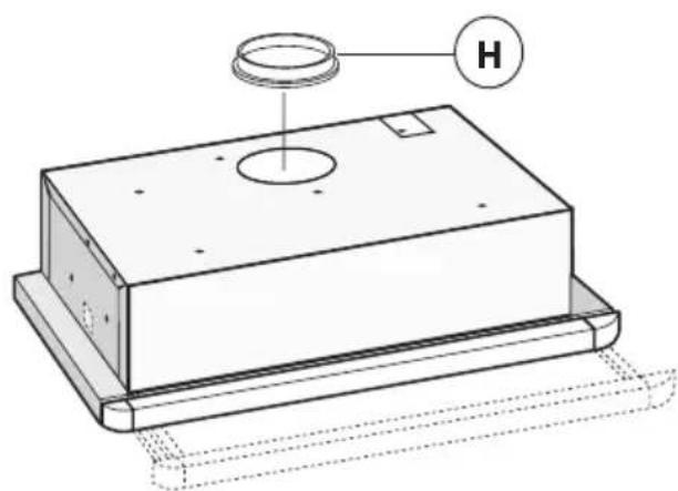
| Included accessories | Connection flange for evacuation (H) |
| Compliance | European WEEE Directive (2002/96/EC) – do not dispose with household waste |
Frequently Asked Questions - HHT6300X HOOVER
User questions about HHT6300X HOOVER
0 question about this device. Answer the ones you know or ask your own.
Ask a new question about this device
Download the instructions for your Range hood in PDF format for free! Find your manual HHT6300X - HOOVER and take your electronic device back in hand. On this page are published all the documents necessary for the use of your device. HHT6300X by HOOVER.
USER MANUAL HHT6300X HOOVER
natural_image
Diagram of a mechanical assembly with a curved component and two mounting holes (no text or symbols)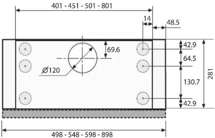
Optional
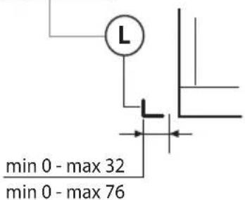
Fig.2
natural_image
Technical line drawing of a rectangular electronic component with a circular top and mounting base, labeled 'H' (no text or symbols beyond label)Fig.3
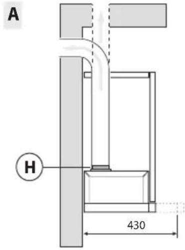
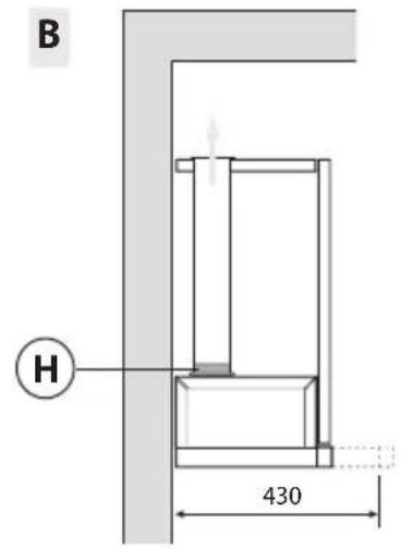
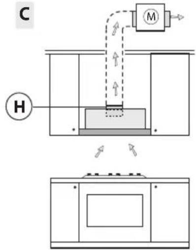
Fig.4
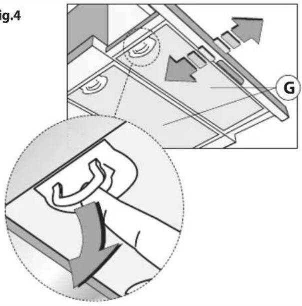
Fig.5
natural_image
Illustration of a hand pressing a button on a circular component, with an 90° angle indicator (no text or symbols on the diagram itself)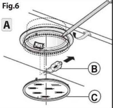
flowchart
graph TD
    A1["A1"] --> A2["A2"]
    A2 --> A3["0"]
    A3 --> A4["*"]
    A4 --> A5["A"]
    B1["B1"] --> B2["B2"]
    B2 --> B3["B3"]
    B3 --> B4["B4"]
    B4 --> B5["B"]
    C["C"] --> C1["Car"]
    C1 --> C2["→"]
    C2 --> C3["→"]
    C3 --> C4["B"]
Fig.8
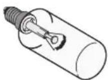
INCANDESCENT
TUBOLAR LAMP
∅ 25mm - L85- E14 - 40W
B
natural_image
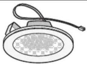
Illustration of a ceiling-mounted lamp with a circular base and cable (no text or symbols)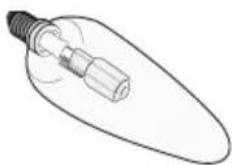
CANDLE
HALOGEN LAMP
∅ 35mm - E14 - 28W
GENERALITÀ
INSTALLATIE INSTRUCTIES
B4 = Toets DERDE SNELHEID
C = Toets Parel controlelampje.
B2 = Toets TWEEDE SNELHEID
B3 = Toets DERDE SNELHEID.
Carefully read the following important information regarding installation safety and maintenance. Keep this information booklet accessible for further consultations. The appliance has been designed for use in the ducting version (air exhaust to the outside - Fig.3A), filtering version (air circulation on the inside - Fig.3B) or with external motor (Fig.3C).
SAFETY PRECAUTION
- Take care when the cooker hood is operating simultaneously with an open fireplace or burner that depend on the air in the environment and are supplied by other than electrical energy, as the cooker hood removes the air from the environment which a burner or fireplace need for combustion. The negative pressure in the environment must not exceed 4Pa (4x10⁻⁵ bar). Provide adequate ventilation in the environment for a safe operation of the cooker hood.
Follow the local laws applicable for external air evacuation.
Before connecting the model to the electricity network:
- Control the data plate (positioned inside the appliance) to ascertain that the voltage and power correspond to the network and the socket is suitable. If in doubt ask a qualified electrician.
- If the power supply cable is damaged, it must be replaced with another cable or a special assembly, which may be obtained direct from the manufacturer or from the Technical Assistance Centre.
- This device must be connected to the supply network through either a plug fused 3A or hardwired to a 2 fase spur protected by 3A fuse.
2. Warning!
In certain circumstances electrical appliances may be a danger hazard.
A) Do not check the status of the filters while the cooker hood is operating.
B) Do not touch bulbs or adjacent areas, during or straight after prolonged use of the lighting installation.
C) Flambè cooking is prohibited underneath the cooker hood.
D) Avoid free flame, as it is damaging for the filters and a fire hazard.
E) Constantly check food frying to avoid that the overheated oil may become a fire hazard.
F) Disconnect the electrical plug prior to any maintenance.
G) This appliance is not intended for use by young children or infirm persons without supervision.
H) Young children should be supervised to ensure they do not play with the appliance
I) There shall be adequate ventilation of the room when the rangehood is used at the same time as appliances burning gas or other fuels.
L) There is a risk of fire if cleaning is not carried out in accordance with the instructions.
This appliance conforms to the European Directive EC/2002/96, Waste Electrical and Electronic Equipment (WEEE). By making sure that this appliance is disposed of in a suitable manner, the user is helping to prevent potential damage to the environment or to public health.

The symbol on the product or on the accompanying paperwork indicates that the appliance should not be treated as domestic waste, but should be delivered to a suitable electric and electronic appliance recycling collection point. Follow local guidelines when disposing of waste. For more information on the treatment, re-use and recycling of this product, please contact your local authority, domestic waste collection service or the shop where the appliance was purchased.
INSTALLATION INSTRUCTIONS
- Assembly and electrical connections must be carried out by specialised personnel.
- Wear protective gloves before proceeding with the installation.
• Electric Connection:
- The appliance has been manufactured as a class II, therefore no earth cable is necessary. The plug must be easily accessible after the installation of the appliance. If the appliance is equipped with power cord without plug, a suitably dimensioned omnipolar switch with 3 mm minimum opening between contacts must be fitted between the appliance and the electricity supply in compliance with the load and current regulations.
- The connection to the mains is carried out as follows:
BROWN = L line
BLUE = N neutral.
- The minimum distance between the support surfaces of the cooking pots on the cooker top and the lowest part of the cooker hood must be at least 65 cm. If a connection tube composed of two parts is used, the upper part must be placed outside the lower part. Do not connect the cooker hood exhaust to the same conductor used to circulate hot air or for evacuating fumes from other appliances generated by other than an electrical source. Before proceeding with the assembly operations, remove the anti-grease filter(s) (Fig.4) so that the unit is easier to handle.
-
In the case of assembly of the appliance in the suction version prepare the hole for evacuation of the air.
-
We recommend the use of an air exhaust tube which has the same diameter as the air exhaust outlet hole. If a pipe with a smaller diameter is used, the efficiency of the product may be reduced and its operation may become noisier.
- If your appliance has been designed for use in habitations supplied with a centralised suction device perform the following operations:
- The switch controls opening and closure of a valve using a thermoelectical device. By placing the switch in the ON position, after a minute, the valve opens rotating 90° allowing suction of the stale air. By placing the switch in the OFF position, the valve closes after 100 seconds.
- Installation:
The following instruction should be followed to carry out the correct installation of the cooker hood.
- Mounting of the cooker hood on the lower side of the cupboard.
- Selection of the version (extraction Fig.3A or filtration Fig.3B).
•Fixing the hood to the lower part of the wall cabinet:
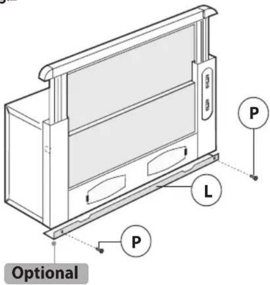
This type of appliance must be fitted inside a cabinet or inside another type of support structure. To fix it in place, use 4 screws which are suitable for the type of cabinet, making holes in accordance with the diagram shown in (Fig.1). To fit the appliance correctly, align the front panel of the cooker hood with the cabinet door and adjust spacer L using screws P (Fig.2), then ensure the appliance meets the cabinet at the rear.
• Extraction through an outside wall:
The appliance expels the fumes through an outside wall or a duct. It is necessary to buy a telescopic pipe in accordance with the standards in use (inflammable) and connect it to flange H (Fig.3A).
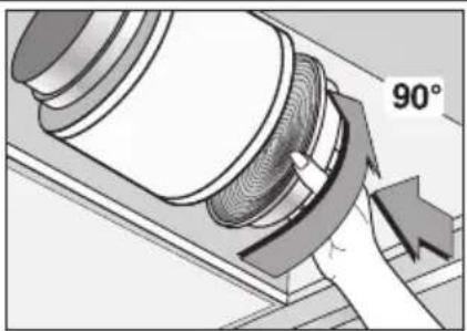
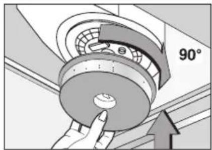
- Recirculation:
To transform the cooker hood from the extraction version to the re circulating one ask your supplier for an activated carbon filter. The filter must be fitted to the extracting group cooker hood in the centre of the fan grille by twisting it by 90 degrees until it is gripped securely (Fig.5). For this operation remove the anti-grease filter(s) G (Fig.4). The clean air is returned into the room through a connecting tube passing inside the cupboard and connected to the ring H (Fig.3B).
USE AND MAINTENANCE
- We recommend that the cooker hood is switched on before any food is cooked. We also recommend that the appliance is left running for 15 minutes after the food is cooked, in order to thoroughly eliminate all contaminated air.
The effective performance of the cooker hood depends on constant maintenance; the anti-grease filter and the active carbon filter both require special attention.
- The anti-grease filter is responsible retaining the grease particles suspended in the air, therefore it is subject to clogging with variable frequency according to the use of the appliance.
- To prevent the danger of possible fires, at least every 2 months one must wash the anti-grease filters by hand using non-abrasive neutral liquid detergents or in the dishwasher at low temperatures and on short cycles.
- After a few washes, colour alterations may occur. This does not give the right to claim their replacement.
- The active carbon filters are used to purify the air that is sent back into the room and its function is to mitigate the unpleasant odours produced by cooking.
- The non-regenerable active carbon filters must be replaced at least every 4 months. The saturation of the active charcoal depends on the more or less prolonged use of the appliance, on the type of kitchen and on the frequency with which anti-grease filter is cleaned.
- Regenerable active charcoal filters must be washed by hand, with non abrasive neutral detergents, or in the dishwasher at a maximum temperature of 65^ C (the washing cycle must be complete without dishware). Remove excess water without damaging the filter, remove the plastic parts, and let the mat dry in the oven for at least 15 minutes approximately at a maximum temperature of 100^ C. To keep the regenerable charcoal filter functioning efficient this operation must be repeated every 2 months. These must be replaced at least every 3 years or when the mat is damaged.
- Before remounting the anti-grease filters and the regenerable active charcoal filters it is important that they are completely dry.
- Clean the hood frequently, both internally and externally, using a cloth dampened with denatured alcohol or
neutral liquid detergents that are non abrasive.
•The lighting .system is designed for use during cooking and not for the prolonged general lighting of the room. The prolonged use of the lighting system significantly decreases the average duration of the bulbs.
- If the appliance is equipped with courtesy lights it is possible to use them for general room lighting for a prolonged amount of time.
- Attention: the non compliance with the hood cleaning warnings and with the replacement and cleaning of the filters entails risk of fires. One therefore recommends keeping to the suggested instructions.
- Replacing halogen light bulbs (Fig.6 A):
To replace the halogen light bulbs B, remove the glass pane C using a lever action on the relevant cracks.
Replace the bulbs with new ones of the same type.
Caution: do not touch the light bulb with bare hands.
- Replacing LED lamps (Fig.6 B):
If the appliance version is with LED lamps, the intervention of a specialised technician is necessary to replace them.
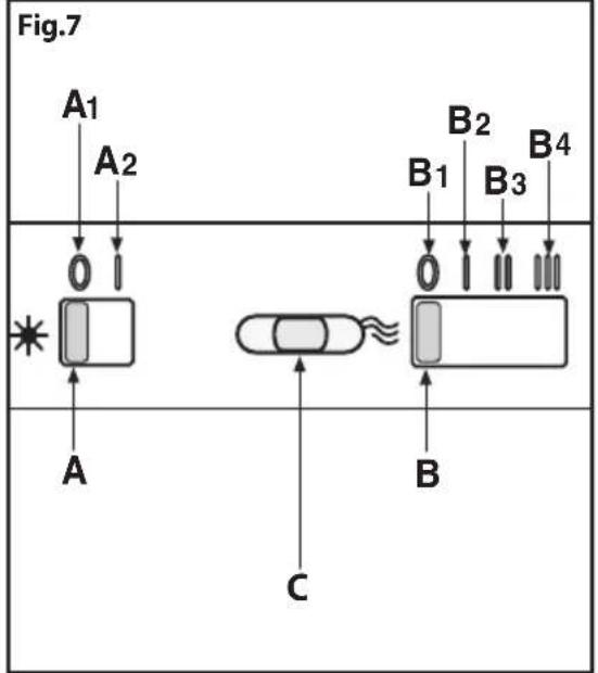
- Commands slider (Fig.7) the key symbols are explained below:
A = Light switch
A1 = Off key
A2 = On key
B = Speed control
B1 = Off key
B2 = FIRST SPEED key
B3 = SECOND SPEED key
B4 = THIRD SPEED key
C = Gemma warning light key.
- Replacing the halogen/incandescent lamps (Fig.8):
Only use lamps of the same type and wattage installed on the device.
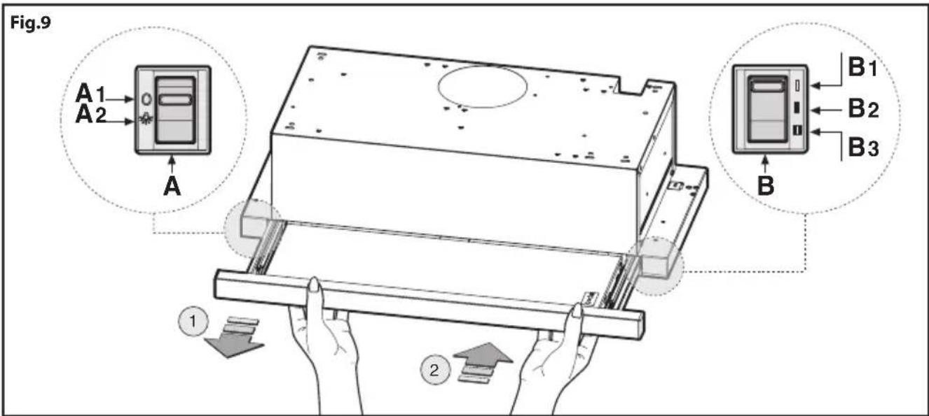
- Commands slider (Fig.9) the key symbols are explained below:
This hood is fitted with a microswitch which allows the activation of the motor speed) through the opening of the telescopic undercarriage. If the telescopic undercarriage is closed the motor speeds cannot be activated. This microswitch does not have an impact on the activation of the lights which must be switched on through the appropriate switch (see Fig.9A).
A = Light switch
A1 = Off key
A2 = On key
B = Speed control
B1 = FIRST SPEED key
B2 = SECOND SPEED key
B3 = THIRD SPEED key.
Warning! If the telescopic undercarriage is closed with the speed set at 2, once it is re-opened, the hood will be reactivated with the same speed in use when the hood was closed.
CUSTOMER ASSISTANCE SERVICE
Before contacting the Technical Assistance Service.
If the product does not operate at all, we advise you to:
- Check that the plug has been inserted into the power socket correctly.
If you cannot identify the cause of the operating anomaly: switch off the appliance (do not subject it to rough treatment)
and contact the Assistance Service.
PRODUCT SERIAL NUMBER. Where can I find it?
It is important that you inform the Assistance Service of your product code and its serial number (a 16-character code which begins with the number 3); this can be found on the guarantee certificate or on the data plate located inside the appliance. This will help to avoid wasted journeys being made by technicians, thereby (and most significantly) saving the corresponding callout charges.
THE MANUFACTURER DECLINES ALL RESPONSIBILITY FOR EVENTUAL DAMAGES CAUSED BY BREACHING THE ABOVE WARNINGS.
ÚVOD'
B2 = F∅RSTÉ HASTIGHED knap
B3 = ANDEN HASTIGHED knap
B4 = TREDIE HASTIGHED knap
C = Kontrollys for Gemma knap.
B2 = ANDEN HASTIGHED knap
B3 = TREDIE HASTIGHED knap.
B2 = Tast HASTIGHET EN
B3 = Tast HASTIGHET TO
B4 = Tast HASTIGHET TRE
C = Tast Gemma varsellampe
- Bytte ut lyspærer/halogenpærer (Fig.8):
Bruk kun pærer som er av samme type og styrke som den som er på apparatet.
•Kommandoer slider (Fig.9) symbolenes betydning:
B2 = tast HASTIGHET TO
B3 = tast HASTIGHET TRE.
natural_image
Stylized black-and-white graphic with a plant and a circular ring of stars containing an euro symbol (no text or numbers present)


- GENERALITÀ
- INSTALLATIE INSTRUCTIES
- SAFETY PRECAUTION
- Before connecting the model to the electricity network:
- Warning!
- INSTALLATION INSTRUCTIONS
- • Electric Connection:
- - Installation:
- •Fixing the hood to the lower part of the wall cabinet:
- • Extraction through an outside wall:
- - Recirculation:
- USE AND MAINTENANCE
- neutral liquid detergents that are non abrasive.
- - Replacing halogen light bulbs (Fig.6 A):
- - Replacing LED lamps (Fig.6 B):
- - Replacing the halogen/incandescent lamps (Fig.8):
- - Commands slider (Fig.9) the key symbols are explained below:
- CUSTOMER ASSISTANCE SERVICE
- PRODUCT SERIAL NUMBER. Where can I find it?
- ÚVOD'
- - Bytte ut lyspærer/halogenpærer (Fig.8):
- •Kommandoer slider (Fig.9) symbolenes betydning:
Brand : HOOVER
Model : HHT6300X
Category : Range hood