FPX 5.1200 - Receiver FOCAL - Free user manual and instructions
Find the device manual for free FPX 5.1200 FOCAL in PDF.
| Product Type | Car Audio Amplifier |
| Model | FPX 5.1200 (FPX Series) |
| Amplification Technology | Class D (depending on model) |
| Number of Channels | 5 channels (estimated) |
| Output Power (RMS) | Up to 120 W x 4 + 400 W x 1 (estimated) |
| Minimum Speaker Impedance | 2 ohms (standard), 4 ohms bridged mode |
| Bandwidth | 10 Hz - 20 kHz |
| Signal-to-Noise Ratio | > 76 dBA |
| Total Harmonic Distortion | 0.01% (minimum) |
| Power Supply | 12 V DC (vehicle) |
| Idle Current | Approximately 1 A |
| Fuses | 2 x 30 A (or more depending on model) |
| Dimensions (W x D x H) | 300 x 150 x 60 mm (estimated) |
| Weight | Approximately 2.5 kg |
| Main Features | Gain adjustment, high-pass/low-pass filter, bass boost, phase (on some models), bridged mode, signal pass-through |
| Maintenance and Cleaning | Clean with a soft dry cloth. Avoid moisture and abrasive products. Do not obstruct ventilation. |
| Spare Parts and Repairability | Replacement fuses available. Remote control optional. Repairs by a Focal authorized dealer. |
| Safety | Do not open the device. Use appropriately sized cables. Disconnect the battery before installation. Observe impedances. |
| Warranty | 2 years (France), subject to return of coupon within 10 days. |
Frequently Asked Questions - FPX 5.1200 FOCAL
User questions about FPX 5.1200 FOCAL
0 question about this device. Answer the ones you know or ask your own.
Ask a new question about this device
Download the instructions for your Receiver in PDF format for free! Find your manual FPX 5.1200 - FOCAL and take your electronic device back in hand. On this page are published all the documents necessary for the use of your device. FPX 5.1200 by FOCAL.
USER MANUAL FPX 5.1200 FOCAL
natural_image
Four technical line drawings of rectangular electronic modules with heat sinks and connectors, shown from different angles (no text or symbols present)English page 3 Français page 17 Deutch seite 31
Thank you for choosing Focal for your car audio system and for sharing in our philosophy: the "Spirit of Sound". This product is made with the best of Focal's technology.
For best results we recommend your FPX amplifier is installed by your Focal dealer. To make full use of its functionalities and, therefore, to enjoy its performance to the full, we advise you to carefully read all the instructions in this booklet and to keep it for future reference. Any problem due to non-compliance with the instructions for use may lead to invalidation of the warranty.
The Focal guarantee only applies if the enclosed guarantee card is returned to us within 10 days of purchase.


CAUTION
This symbol is used for important instructions. Failure to follow these instructions may lead to serious injury or damage to property.
Contents
- 1 FPX amplifier
- 1 User manual
- 1 Set of accessories
- 1 Remote control (FPX 1.1000 and FPX 2.750)

CAUTION
- Do not activate any function that might distract you when driving the vehicle. Functions and settings requiring prolonged attention should only be used when the vehicle is completely stopped. Always stop the vehicle in a safe location before accessing these functions. Risk of causing an accident.
- When driving the vehicle, keep the volume low so that noises outside the vehicle can be heard. Risk of causing an accident.
- Do not open the casing of your FPX amplifier and do not modify it in any way. Risk of accident, fire or electric shock.

Your Focal-JMlab product was developed and manufactured with high-quality materials and components which can be recycled and/or re-used. This symbol indicates that electrical and electronic equipment must be disposed of separately from normal garbage at the end of its operational lifetime. Please dispose of this product by bringing it to your local collection point or recycling centre for such equipment. This will help to protect the environment in which we all live.

CAUTION
- Only use your FPX amplifier on mobile 12 volt applications. Any other use than the designed application entails a risk of fire, electric shock or injury.
- Use fuses of the correct amperage. Risk of fire or electrical discharge.
- Do not obstruct your FPX amplifier's heat sink. It may overheat internally and cause a fire.
- Make connections properly. Check the gauge and type of cable. Risk of fire, injury and/or damage to the amplifier.
- Do not use nuts or bolts from the steering or braking circuits, from tanks or reservoirs, seat belts or other safety equipment for making the ground (earth) connection. The use of these items for grounding (earthing) could deactivate the vehicle control system and cause a fire or other damage.
- Keep small items that may be swallowed, such as bolts, accessories or screws out of the reach of children. Swallowing such items could lead to serious injury. If swallowed, consult a doctor.
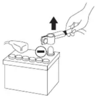
- Before commencing installation, disconnect the negative battery terminal to avoid risk of injury, fire or material damage. (Fig. 1)
natural_image
Illustration of a hand using a tool to press down a battery component (no text or symbols present)fig. 1

WARNING
Prolonged listening at high volume, above 110dB, can cause permanent hearing damage. Listening at volumes above 130 dB, even for short periods can lead to untreatable hearing damage.
Stop listening in the event of any problem. Failure to observe this precaution may lead to injury or damage to the equipment. If a malfunction persists, return the unit to your Focal dealer for repair.
Use the specified accessories and install them correctly. Use only the accessories specified in the user manual and those provided in the packaging. The use of other components may cause internal damage to the product, or may lead to its incorrect installation. Parts used may become loose and cause damage or the technical failure of the product. Risk of accident, fire or electric shock.
Do not install the unit in highly damp or dusty areas. Avoid installing the unit in parts of the vehicle subject to high damp or excessive dust. Penetration of the unit by moisture or dust could lead to a failure.
Installing your FPX amplifier
Installing this product requires technical skill and experience. If you are not sure of your ability to install the amplifier, entrust this task to a Focal dealer in order to take full advantage of everything your FPX amplifier can do.
Cabling your FPX amplifier
Only use the connection points specified in the user manual and the accessories supplied.
The speaker cable must ONLY be used to connect the amplifier to the speakers. The gauge of the power cables must match that shown in the table (paragraph 3.1). This gauge depends on the power of the amplifier and the cable length required. Use double or triple shielded RCA cables to prevent any interference to the low level signal.
Operating time for your FPX amplifier
Avoid using the amplifier for extended periods without starting the vehicle. This can lead to flattening the battery.
Ventilation
It is essential to leave the upper part of your FPX amplifier uncovered to prevent overheating.
Items required for installation (in addition to accessories provided)
- 2 appropriately sized cable sheaths (1 for the power cable and one for the set comprising speaker cables, remote, RCA modulation)
- Multimeter (volts/amps)
- Soldering iron and solder
- Crimping tool
- Wire stripper
- Wire cutter
- Battery terminal spanner
- Hand drill and drill bits
- Heat shrink sleeving in appropriate diameters for the different cables
• Power cable of appropriate length and gauge - Remote switch-on wire of appropriate length and gauge (REM input on amplifier)
• Ground (earth) wire of appropriate length and gauge - Fuse holder and suitable fuse
- Connector to positive (+) battery terminal
- Connector to vehicle chassis (-)
- Bolt with 6 mm head (minimum) with appropriate nut for grounding (earthing) to vehicle chassis
Installation
This section covers points relating to the vehicle that must be taken into account for the installation of your amplifier. You will save time by planning the positioning of your system and its cabling in advance.
During this preparatory phase, ensure that all adjusters remain accessible once installation is complete.
Before commencing installation please scrupulously follow the following instructions:
1 - Read the instructions in full and be sure that you fully understand them before installing your amplifier.
2 - Disconnect the cable from the negative terminal on the vehicle battery before beginning installation (Fig. 1).
3 - For ease of fitting we suggest you put all wires in position before installing your amplifier.
4 - Route the RCA, speaker and REM cables away from power cables to avoid any signal interference.
5 - Use good quality connectors/fittings or good quality soldered joints when connecting the amplifier to ensure a secure installation and to minimise signal or power losses.
6 - Before carrying out any operation ensure you are not cutting or drilling the fuel tank, any fuel, brake, hydraulic or vacuum line or any electrical wiring or safety-related item.
7 - Never run any wiring under the vehicle. It is essential to run wiring inside the vehicle. When running cables, ensure they do not interfere with operation of the vehicle. Cabling that obstructs or passes over such items as the steering wheel, the pedals (brake, accelerator and clutch, etc.) could be extremely dangerous.
8 - Avoid running wires over or through sharp edges. All wiring routed through metal must be protected by a grommet. Route wiring away from moving parts (e.g. seat rails) and sharp or pointed edges. This will also protect cables from being pinched or damaged with the consequent risk of an electrical short-circuit.
9 - Always use fuses to protect the battery and the electrical circuit from any potential damage. Install a fuse-holder and an appropriate fuse in the 12V+ power supply cable less than 40cm from the battery terminal. Ideally, this distance should be as short as possible (Fig. 7).
10 - Prepare the chassis ground (earth) by removing all traces of paint from the metal surface, thus ensuring a good ground (earth) contact. Ground (earth) connections should be as short as possible and ALWAYS connected to metal welded to the vehicle bodywork or chassis (Fig. 2). The grounding (earthing) point usually chosen is the one used to connect the negative terminal of the battery to the vehicle chassis.
11 - NEVER install this product in a vehicle's engine compartment. To do so would void the warranty.
1 - Positioning your FPX amplifier
Choosing a correct location for your FPX amplifier
Because of the amplifier's power, it needs heat dissipation for its operation. For this reason the amplifier must be mounted in a ventilated location, especially above it. Avoid fitting it into any location that is close-fitting or covers the amplifier in its immediate vicinity.
2 - Securing your FPX amplifier in place
Position your amplifier in the desired location and mark it.
Mark the attachment points in its support.
Use the mounting screws supplied (screws supplied are suitable for screwing into a wood base).
3 - Cabling your FPX amplifier

CAUTION
If you have any doubt over your ability to correctly install the amplifier and wiring, entrust this task to a Focal dealer/installer.
3 - Cabling your FPX amplifier

WARNING
Do not run the power cables near the low level inputs, high level inputs, antenna or sensitive equipment or cabling. The power cables carry a high current, capable of interfering with the audio signal.

WARNING
Use the shortest possible cable lengths to optimise the quality of the installation and limit signal losses.

WARNING
Before beginning the connection phase, remove the negative (−) terminal from the battery of the vehicle (fig. 1).
3.1 Choosing cable of the correct gauge
Your FPX amplifier requires a power supply of the correct amperage.
The cable gauge to be used depends on the distance of the cable from the battery, as recommended in the following table:
| Amplifier Amperage Length of cable (meters) | ||||
| 0-2 m 2-4 m 4-6 m | ||||
| FPX 4.800 and FPX 2.750 | 60 A 16mm | ^2 /5 AWG 21mm | ^2 /4 AWG 35mm | ^2 /2 AWG |
| FPX 1.1000 90 A | 21mm | ^2 /4 AWG 35mm | ^2 /2 AWG 53mm | ^2 /0 AWG |
| FPX 4.400 SQ 50 A | 8mm | ^2 /8 AWG 16mm | ^2 /5 AWG 21mm | ^2 /4 AWG |
It is essential to scrupulously adhere to the recommendations in this table for the safety of your electrical system; it is also important to maintain the maximum performance of your FPX amplifier.
3.2 - Cabling your FPX amplifier's input signals
Route all the modulation cables (RCA), speaker cables, and the REM cable together, isolating them from other high-power consumption equipment in the vehicle and, in particular, electrical motors (e.g. windscreen wiper motor, etc.) Do not cut any cables down yet. You will do this later.
3.3 - Wiring your FPX amplifier's power supply
3.3.1 - Route the positive (+) power cable, taking care to keep it away from the cables you have already positioned, to avoid any interference. DO NOT CONNECT THE CABLE YET.
FPX Premium amPliFier
User manual
3.3.2 - Locate the negative (-) power cable. This cable should be as short as possible and ideally should not exceed 1 meter in length, in order to ensure an optimal connection between the amplifier and the vehicle chassis. The cable and its gauge must be in accordance with the table in 3.1. Locate an appropriate ground (earth) point, then sand it to remove all traces of paint or other finish, thus optimising the quality of the connection. Drill through the sheet metal you have previously sanded, making a hole to match the bolt you have chosen, ensuring you are well clear of all cable routes, reservoirs or tanks or other sensitive vehicle parts. Solder and insulate (using heat shrink sleeving) the earth cable to the FPX amplifier earth connector supplied (Fig. 2).
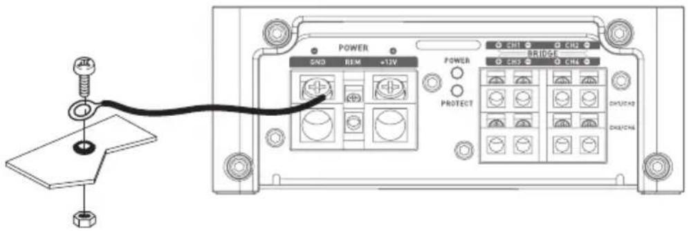
text_image
POWER SND REM +13V POWER PROTECT CH1 CH2 CH3 CH4 DH/CHD DH/CHDfig. 2
3.4 - Connecting input connectors to your FPX amplifier
You may now begin the input/output cable connection phase.
Connect the RCA connectors (Fig. 3), paying attention to polarity and distribution. Connect the other end to the amplifier's INPUTS connection panel.
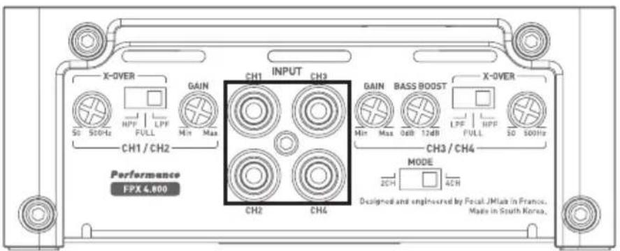
text_image
X-OVER S0 S10Hz HPP FULL Min Max CH1 / CH2 Performance FPX 4,800 GAIN CH1 INPUT CH3 MIN Max CH3 / CH4 MODE 2CH 4CH Designed and engineered by Focal JMala in France. Made in South Korea.fig. 3
FPX Premium amPliFier
User manual
3.5 - Connecting the speakers and the remote to your FPX amplifier
Solder and insulate (using heat shrink sleeving) the REMOTE cable to the cable connector provided (Fig. 4). Connect the other end of the REMOTE cable to the REMOTE terminal on the head unit.
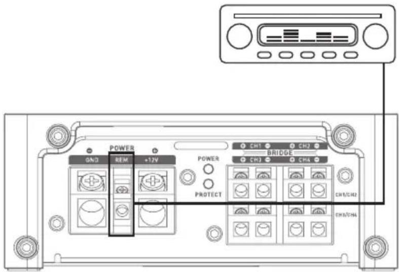
text_image
POWER GND REM +12V POWER PROTECT CH1 CH2 BRIDGE CH3 CHA CH1/CH2 CHA/CHAfig. 4
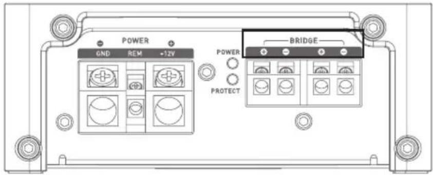
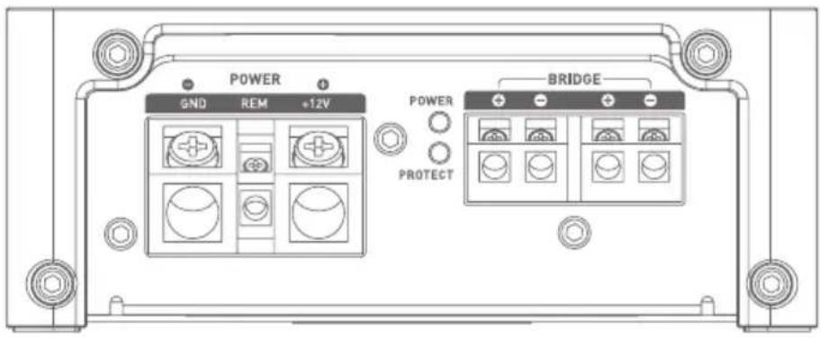
Finally, connect the speaker cables to the amplifier, taking care to match polarities (+ to +, - to -). (Fig. 5).

text_image
POWER GND REM +12V POWER PROTECT CH1 CH2 BRIDGE CH3 CH4 CH1/CH2 CH3/CH4fig. 5

WARNING
All speakers or speaker sets cabled to your FPX 4.800, FPX 4.400 SQ or FPX 2.750 amplifier must always have an impedance greater than 2 ohms.

WARNING
All speakers or speaker sets cabled to your FPX 1.1000 amplifier must always have an impedance greater than 1 ohm.
FPX Premium amPliFier
User manual

WarNiNG
In bridged mode, all speakers or speaker sets connected to your FPX 4.800, FPX 2.750 or FPX 4.400 SQ must always have an impedance greater than 4 ohms.
Any use of lower impedances would result in the voiding of the warranty.
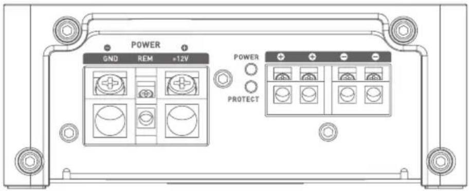
To use a FPX amplifier in bridged mode and thus double the power available, observe the connections and polarities shown below in: "BRIDGE" (Fig. 6).
FPX 4.800
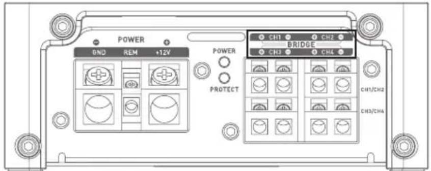
text_image
POWER DND REM +12V POWER PROTECT CH1 CH2 BRIDGE CH3 CH4 CH1/CH2 CH3/CHAfig. 6
FPX 2.750
text_image
POWER GND REM +12V POWER BRIDGE PROTECTfig. 6
FPX 4.400

text_image
CH1 BRIDGE CH3 CH4 FUSES POWER 12V REN GND Performance TPX 6.409 SD Designed and engineered by Pocal JIMak in France, Made in South Korea.fig. 6
FPX Premium amPliFier
User manual
3.6 - Power supply wiring

WARNING
The cable connecting the positive (+) battery terminal to the "+BATT" terminal on the amplifier must ALWAYS have a fuse suitable for the power of your amplifier, positioned 40 cm or closer to your vehicle battery.
Fuse holder connections must be sealed.
Disassemble the fuse holder, taking care to remove the fuse. Secure the base of the fuse holder.
Cut a length of power cable between 10 and 40 cm (max.). Strip 1 cm and tin. Screw the cable into the terminal on the battery side of the fuse holder. Crimp the power cable into an appropriate connector and screw this to a source of battery power.
Strip 1 cm at the end of the remaining length of cable and tin. Screw the cable into the other terminal of the fuse holder.
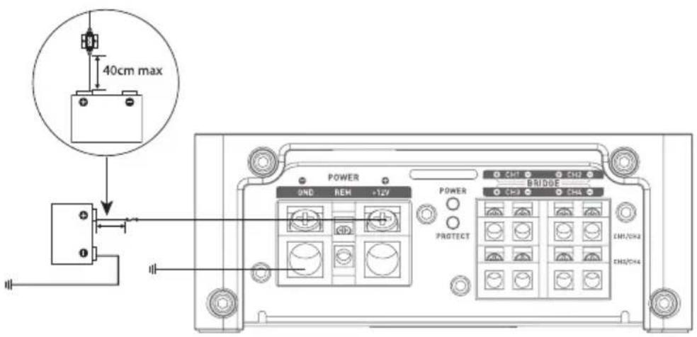
text_image
40cm max POWER UND REM +127 POWER BRIDGE CH1 CH2 CH3 CH3 CH4 PROTECT CH1/CH2 CH2/CH4fig.7
Solder and insulate (using heat shrink sleeving) the positive (+) power cable to the FPX amplifier connector supplied (Fig. 7).
3.7 - Start-up and checking
The connection phase is now complete. It now remains to check the power supply is good and the correct operation of the system (head unit/amplifier/speakers). Set the source gain to minimum. Set the gain on your amplifier at 1/3 of its total travel. Power up all the components. Once all components are switched on, test at low volume.
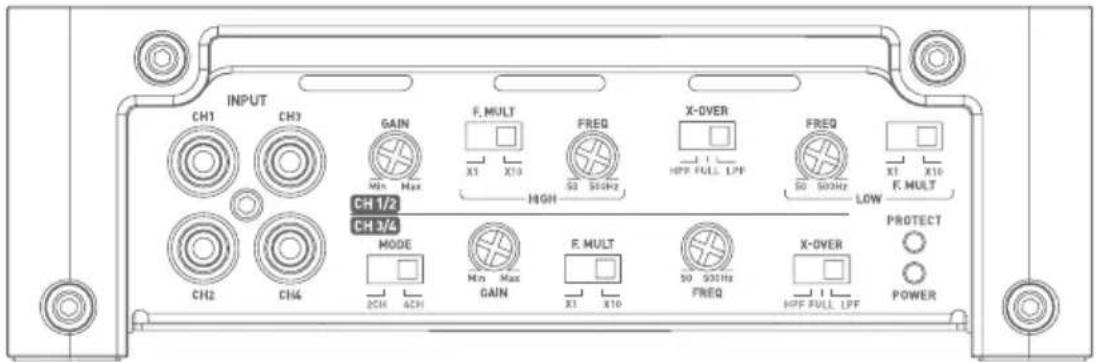
4 - Control panel and connections
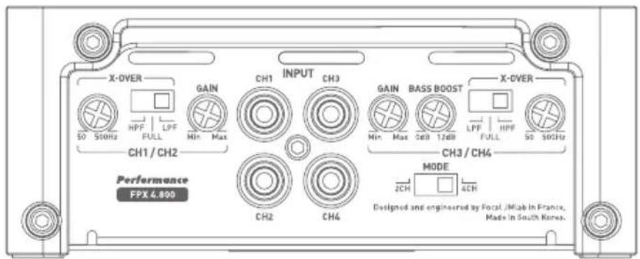
FPX 4.800
text_image
X-OVER 50 50Hz HPF FULL GAIN Min Max CH1 / CH2 Performance FPX 4.800 CH1 INPUT CH3 GAIN BASS BOOST Min Max Cdd 12dB LPF FULL SO 50GHz CH3 / CH4 MODE ZCH ACH Designed and engineered by Focal JIMab in France, Made in South Korea.fig.8
FPX Premium amPliFier
User manual
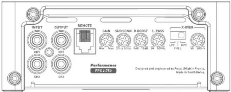
FPX 2.750

text_image
INPUT OUTPUT REMOTE GAIN SUB SONIC B.BOOST L.PASS X-OVER Min Max 20Hz 50Hz dB 13dB SO 500Hz LPF FULL HPF SD 500Hz Performance FPX 2.750 Designed and engineered by Focal JIMab In France. Made in South Korea.FPX 4.400 SQ
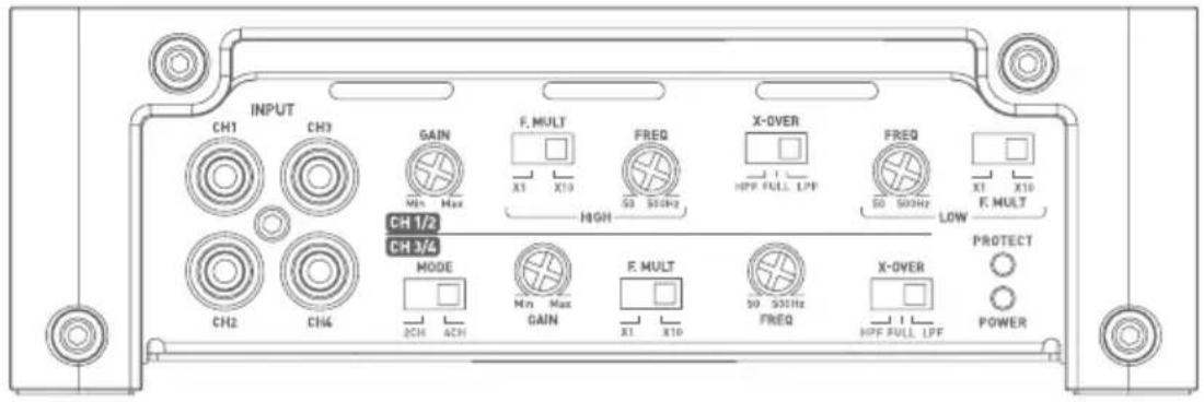
text_image
INPUT CH1 CH2 GAIN F. MULT FREQ X-OVER FREQ X1 X10 50 50Hz HPF FULL LPF 50 50Hz LOW F. MULT CH 1/2 HIGH CH 3/4 MODE F. MULT X-OVER PROTECT CH2 CH4 2CH 4CH Min Max GAIN X1 X10 50 50Hz FREQ HPF FULL LPF POWERFPX 1.1000

text_image
INPUT OUTPUT REMOTE GAIN SUB SONIC PHASE BASS BOOST LPF MIN Max 20Hz 50Hz 0° 180° 6dB 12dB 30 250Hz Performance FPX 1.1000 Designed and engineered by Focal JMiab In France. Made in South Korea.FPX Premium amPliFier
User manual
INPUT: These connectors are for low level signal inputs.
OUTPUT: These connectors (FPX 1.1000 and FPX 2.750) allow mirroring.
REMOTE: This connector (FPX 1.1000 and FPX 2.750) is for connecting the accessory volume control.
GAIN: The rotary GAIN control is for adjusting the level of the signal entering the amplifier. Voltage gain varies from 0.2 to 5V. Optimisation of the performance of the audio system consists of applying the maximum gain upstream in the system and the lowest gain downstream.
This control should be adjusted to suit the level of the sound source (line output level).
Start by setting the amplifier gain at its lowest level. Gradually increase the level (volume) of the source up to 3/4. Increase the gain on the amplifier up to the maximum desired listening level. Reduce the level if distortion occurs.
MODE: This switch (FPX 4.800 and FPX 4.400 SQ) allows channels 3 and 4 to mirror, if required, the signals from channels 1 and 2.
Thus, if you only have one stereo output (a right and a left), you can still amplify all four channels by activating 2CH mode. If you wish to use FPX in its four independent channel mode, select 4CH.
PHASE (°): The rotary PHASE control is used to adjust channel phasing with the rest of the system.
A readjustment of the phase of the subwoofer makes it possible for the subwoofer and the rest of the speakers to play simultaneously at the crossover frequency. For a theoretical signal period, one of the sources is slightly shifted so that at the listening position the phasing is perfect.
X-OVER MODE: This switch enables users to choose between a high-pass filter (HPF), a low-pass filter (LPF) or non filtered mode (FULL).
X-OVER FREQ (Hz): Adjustment of the cross-over filter frequency. This rotary control adjusts the setting of the low-pass or high-pass filter. The value selected defines the frequency up to which or from which the signal will be cut.
F-MULT: This switch activates a 10X multiplier for the setting value of the cut-off frequency.
SUBSONIC: This rotary control is used to remove sub-bass frequencies below a selected frequency.
BASS BOOST: This rotary control is used to raise the bass sound level from 0 to 12 dB.
FPX 4.800

text_image
POWER GND REM +12V POWER PROTECT CH1 CH2 BRIDGE CH3 CH4 CH1/CH2 CH2/CH4fig.9
FPX Premium amPliFier
User manual
FPX 2.750

text_image
POWER GND REM +12V POWER BRIDGE PROTECTFPX 4.400SQ
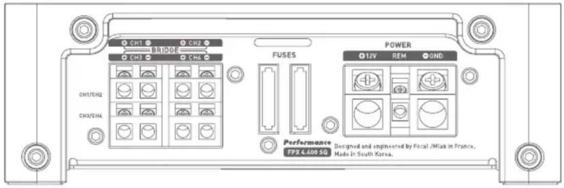
text_image
CH1 CH2 BRIDGE CH3 CH4 FUSES POWER 1J/V REM OND CH1/CH2 CH3/CH4 Performance TPX 4.600 SQ Designed and engineered by Fecal JMiaa in France. Made in South Korea.FPX 1.1000

text_image
POWER GND REM +12V POWER PROTECTFPX Premium amPliFier
User manual
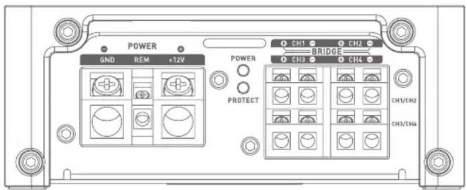
+12V: The +BATT connector is designed to accept the power cable that connects the amplifier with the positive (+) terminal on the vehicle battery.
GND: The GND (ground) connector is designed to accept the negative (-) power cable that connects the amplifier to the vehicle chassis.
REM: The REM connector is for the connection between the amplifier and the source (head unit) via a REM or REMOTE output on the head unit. This switches the amplifier on automatically when the source (head unit) is switched on.
POWER and PROTECT: These indicator lights are for checking that the amplifier is working correctly.
The POWER light, continuously lit, indicates that the unit is working correctly.
The PROTECT light, continuously or intermittently lit, indicates that the product is working abnormally. Refer to troubleshooting in 5.
FUSES: The FUSES connector is for holding the amplifier fuses. Ensure that any replacement fuses perfectly match the amperage of the originals.
5 - Troubleshooting
The statuses of the various LEDs are used to indicate certain failure modes or causes of breakdowns.
Check all possible cases below. If, after these checks, normal operation is not regained, please refer the issue to your FPX amplifier's installer or dealer.
| Status of Indi-cator LEDs | Presence of sound | Possible origin Action | |
| PROTECT red NO | Output short circuit | Turn audio system offCheck speakers, minimum impedance of speakers, speaker connections and cables | |
| Off NO | No power or poor power | Turn audio system offCheck presence of 12 VCheck power cables and their polarityCheck fuses | |
| PROTECT Flashing red | Distorted, intermittent or no sound | Overheating | Turn head unit offAllow your amplifier to cool before resuming use |
| Off NO No | REM signal | Turn head unit onCheck for voltage at REM terminal | |
| Off NO Fuse failure | Turn head unit offCheck fuses and replace if necessary | ||
| POWER Flashing green | YES/NO or distorted | Ground (earth) problem | Turn head unit offCheck continuity of connection between GND terminal and vehicle chassis |
FPX Premium amPliFier
User manual
6 - Technical specifications
| FPX 4.800 Class D 4/3/2 channel amplifier | FPX 2.750 Class D 2 channel/mono amplifier | FPX 4.400SQ Class AB 4/3/2 channel amplifier | FPX 1.1000 Class D mono amplifier | |
| CEApower(4ohms) | 4x120 WRMS 2x220 W | RMS 4x70 WRMS 1x420 | WRMS | |
| Max. power (2 ohms) | 4x185 WRMS 2x385 W | RMS 4x100 WRMS 1x700 | WRMS | |
| Max. power (4 ohms bridged) | 2x370 WRMS 1x770 W | RMS 2x200 WRMS 1x1000 | WRMS | |
| Bandwidth | 10Hz - 20KHz 20Hz - | 20KHz 10Hz - 22KHz 15Hz - 250Hz | ||
| Minimum total harmonic distortion | 0.01% 0.01% 0.04 % 0.08 % | |||
| Crosstalk (1 KHz) | >55dB >72dB >54dB - | |||
| SNR (1W/A) | >76dBA >76dBA >77 | dBA >76dBA | ||
| Subsonic filter | - | 20Hz-50Hz(12dB/oct) | - | 10Hz-50Hz(24dB/oct) |
| High-pass/low-pass filter | Configurable High-pass/low-pass 50Hz-500Hz | Configurable High-pass/low-pass 50Hz-500Hz | Configurable High-pass/low-pass 40Hz-5000Hz | Low-pass 50Hz-250Hz(24dB/oct) |
| Bass Boost | 0 to 12 dB linear (3⁄4) 0 to 12dB linear - 0 to 12dB linear | |||
| Phase | --- 0 to 180° linear | |||
| Full-range function | ✓ ✓ ✓ | - | ||
| Mirror mode | ✓ | - | ✓ | - |
| Standby current (A) | 1.1 A 0.95 A 0.6 A 1.75 A | |||
| Fuses | 2x30 A 2x30 A 2x30 A 3x30 A | |||
| Remote control | - | ✓ | - | ✓ |
| Protection | Short circuit/low impedance/reverse polarity /DC/voltage drop/overheat protection | |||
| Dimensions (LxWxH) | 9^1/64 × 5^13/64 × 2^3/32" (237x132x53mm) | 9^1/64 × 5^13/64 × 2^3/32" (237x132x53mm) | 12^23/64 × 6^57/64 × 2^1/4" (314x175x57mm) | 11^1/16 × 5^13/64 × 2^3/32" (297x132x53mm) |
| Weight (kg) | 4.40lbs (2kg) 4.40lbs (2kg) 8.16lbs (3.7kg) | 5.62lbs (2.55kg) | ||
Warranty conditions
In the event of a problem, please contact your Focal dealer. The warranty for France for all Focal equipment is 2 years. In case of faulty equipment, this must be sent at your expense, in its original packaging, to the dealer, who will test the equipment and determine the nature of the fault. If the equipment is under warranty, it will be returned to you or replaced with pre-paid shipping. If not under warranty, you will be given an estimate for repair. The warranty does not cover damage arising from improper use or incorrect wiring.
Outside France, Focal equipment is covered by a guarantee with terms and conditions set locally by each country's official Focal distributor in accordance with laws in force in the territory in question.
natural_image
Illustration of a hand using a tool to adjust or install a battery component (no text or symbols present)text_image
X-OVER 50 510Hz HPP FULL GAIN Min Max CH1 / CH2 Performance FPX 4,800 CH1 INPUT CH3 GAIN BASS BOOST X-OVER Min Max 0dB 12dB LPF FULL 50 500Hz CH3 / CH4 MODE 20CH 4CH Designed and engineered by Focal JMlab in France. Made in South Korea.fig. 3
text_image
CH1 BRIDGE CH3 CH4 FUSES POWER 12V REM GND Performance FPX 6.009 SD Designed and engineered by Focal JMish in France, Made in South Korea.fig. 6
text_image
X-OVER 50 500Hz HPF FULL GAIN Min Max CH1 / CH2 Performance FPX 4.800 CH1 INPUT CH3 GAIN Max GAIN Max CdB 12dB CH3 / CH4 MODE 2CH ACH Designed and engineered by Focal JIMab in France, Made in South Korea.fig.8
FPX 2.750
text_image
INPUT OUTPUT REMOTE GAIN SUB SONIC B.BOOST L.PASS X-OVER Min Max 20Hz 50Hz 1dB 12dB 50 500Hz LPF HPF FULL SD 500Hz Performance FPX 2.750 Designed and engineered by Facat JMIab In France. Made in South Korea.FPX 4.400 SQ
text_image
INPUT CH1 CH3 GAIN F. MULT FREQ X-OVER FREQ X1 X10 Min Max X1 X10 SD 50Hz HPF FULL LPF SD 50Hz Low F. MULT CH 1/2 HIGH LOW F. MULT CH 3/4 MODE F. MULT X-OVER PROTECT 2CH 4CH MIN Max GAIN X1 X10 SD 50Hz FREQ HPF FULL LPF POWERFPX 1.1000

text_image
INPUT OUTPUT REMOTE GAIN SUB SONIC PHASE BASS BOOST LPF MIN Max 20Hz 50Hz 0° 180° 0dB 12dB 30 250Hz Performance FPX 1.1000 Designed and engineered by Focal JMiab In France. Made in South Korea.text_image
CH1 CH2 BRIDGE CH3 CH4 FUSES POWER 1J/V REM OND CH1/CH2 CH3/CH4 Performance TPX 4.600 SQ Designed and engineered by Fecal JMiaa in France. Made in South Korea.FPX 1.1000

text_image
POWER GND REM +12V POWER PROTECTtext_image
X-OVER S0 S10Hz HPP FULL Min Max CH1 / CH2 Performance FPX 4,800 GAIN CH1 INPUT CH3 MIN Max CH3 / CH4 MODE 2CH 4CH Designed and engineered by Focal JMala in France. Made in South Korea.Abb. 3
FPX PREMIUM AMPLIFIER
Gebrauchsanleitung
text_image
CRI BRIDGE CRI CRA FUSES POWER 12V REM GND Performance TPX 6409-5D Designed and engineered by Pocal J/Mask in France, Made in South Korea.Abb. 6
FPX PREMIUM AMPLIFIER
Gebrauchsanleitung
text_image
X-OVER S0 550Hz HPF FULL GAIN Min Max CH1 / CH2 Performance FPX 4.800 CH1 INPUT CH3 GAIN BASS BOOST Min Max Cdd 12dB LPF FULL SO SOCH CH3 / CH4 MODE 2CH 4CH Designed and engineered by Focal /Mlab in France, Made in South Korea.fig.8
FPX Premium amPliFier
Gebrauchsanleitung
FPX 2.750
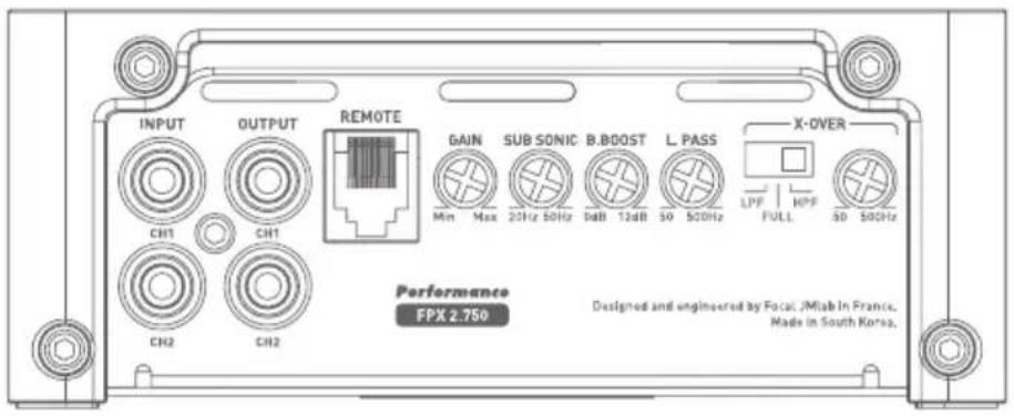
text_image
INPUT OUTPUT REMOTE GAIN SUB SONIC B.BOOST L.PASS X-OVER Min Max 20Hz 50Hz dB 13dB SO 500Hz LPF HPP FULL SD 500Hz Performance FPX 2.750 Designed and engineered by Focal JIMab In France. Made in South Korea.FPX 4.400 SQ

text_image
INPUT CH1 CH2 GAIN F. MULT FREQ X-OVER FREQ X1 X10 HIGH 50 50Hz 50 50Hz LOW F. MULT CH 1/2 CH 3/4 MODE F. MULT X-OVER PROTECT CH2 CH4 2CH 4CH Min Max GAIN X1 X10 50 50Hz FREQ HPF FULL LPF POWERFPX 1.1000
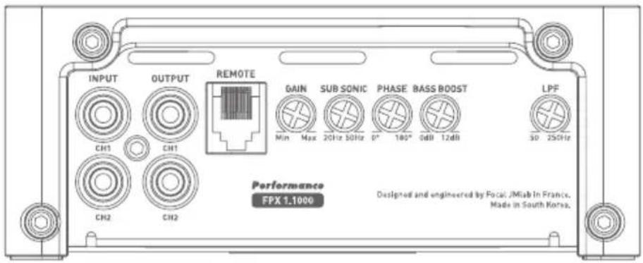
text_image
INPUT OUTPUT REMOTE GAIN SUB SONIC PHASE BASS BOOST LPF MIN Max 20Hz 50Hz 0° 180° 6dB 12dB 30 250Hz Performance FPX 1.1000 Designed and engineered by Focal JMiab In France. Made in South Korea.FPX Premium amPliFier
Gebrauchsanleitung
INPUT: These connectors are for low level signal inputs.
OUTPUT: These connectors (FPX 1.1000 and FPX 2.750) allow mirroring.
REMOTE: This connector (FPX 1.1000 and FPX 2.750) is for connecting the accessory volume control.
GAIN: The rotary GAIN control is for adjusting the level of the signal entering the amplifier. Voltage gain varies from 0.2 to 5V. Optimisation of the performance of the audio system consists of applying the maximum gain upstream in the system and the lowest gain downstream.
This control should be adjusted to suit the level of the sound source (line output level).
Start by setting the amplifier gain at its lowest level. Gradually increase the level (volume) of the source up to 3/4. Increase the gain on the amplifier up to the maximum desired listening level. Reduce the level if distortion occurs.
MODE: This switch (FPX 4.800 and FPX 4.400 SQ) allows channels 3 and 4 to mirror, if required, the signals from channels 1 and 2.
Thus, if you only have one stereo output (a right and a left), you can still amplify all four channels by activating 2CH mode.
If you wish to use FPX in its four independent channel mode, select 4CH.
PHASE (°): The rotary PHASE control is used to adjust channel phasing with the rest of the system.
A readjustment of the phase of the subwoofer makes it possible for the subwoofer and the rest of the speakers to play simultaneously at the crossover frequency. For a theoretical signal period, one of the sources is slightly shifted so that at the listening position the phasing is perfect.
X-OVER MODE: This switch enables users to choose between a high-pass filter (HPF), a low-pass filter (LPF) or non filtered mode (FULL).
X-OVER FREQ (Hz): Adjustment of the cross-over filter frequency. This rotary control adjusts the setting of the low-pass or high-pass filter. The value selected defines the frequency up to which or from which the signal will be cut.
F-MULT: This switch activates a 10X multiplier for the setting value of the cut-off frequency.
SUBSONIC: This rotary control is used to remove sub-bass frequencies below a selected frequency.
BASS BOOST: This rotary control is used to raise the bass sound level from 0 to 12 dB.
FPX 4.800
text_image
POWER GND REM +12V POWER PROTECT CH1 CH2 BRIDGE CH3 CH4 CH1/CH2 CH2/CH4fig.9
FPX Premium amPliFier
Gebrauchsanleitung
FPX 2.750
text_image
POWER GND REM +12V POWER BRIDGE PROTECTFPX 4.400SQ

text_image
CH1 CH2 BRIDGE CH3 CH4 FUSES POWER 1J/V REM OND CH1/CH2 CH3/CH4 Performance TPX 4.600 SQ Designed and engineered by Fecal JMiaa in France. Made in South Korea.FPX 1.1000
text_image
POWER GND REM +12V POWER PROTECTInternational Guarantee
For the validation of the Focal guarantee, send back this sheet within 10 days to the following address:
Now it's possible to register on line : www.focal.com/warranty
About yourself:
Your name: ____ . Your age: ____ . Your job: ____
Your full address: ____
Your e-mail address:
Your hobbies:
At home, do you own Hi-Fi loudspeakers? □ - Yes - Nq□
If yes, specify the brand: ____
Do you read the press? □ - Yes - No□
If yes, which magazine(s)?
Your audio/video equipment (brands and models) before the acquisition of Focal products:
CD player/tuner: Multimedia player:
Navigation system: Amplifier:
Speakers:____ Enclosure/subwoofer:____
Other elements:
Your choice for the purchase of this Focal model was made according to:
□ - Dealer's advice - Friend's or family's advice □
□ - Visiting an exhibition/a show - Quality-price ratio
□ - Sound quality/listening room - Already own Focal products
□ - Reliability/manufacturing quality □ - Catalogues
□ - Design/Finish - French product
□- Article in the press (if yes, specify the title of the magazine) ____ □- Other : ____
Your Focal product:
Model: Serial number:
Dealer's name: City:
Date of your purchase: Price of your purchase:
Did you leave the product installation to your dealer's care? □ - Yes - No□
If not, why? Car model:
This information is necessary to our company to deal with your request. It is registered in our customer file and can give you the right to have access to and correct the information that concerns you through our customer service [+33 477 435 700].
If you do not wish to have your data used by our partners on commercial purpose, tick this box. □ If you do not wish to receive commercial propositions from our partners by e-mail, please tick this box. □
You may receive commercial offers from our company for products similar to those you have bought.
If you do not wish to, tick that box. □ The information given on this page will remain confidential.