FDP 6.900 V2 - Receiver FOCAL - Free user manual and instructions
Find the device manual for free FDP 6.900 V2 FOCAL in PDF.

User questions about FDP 6.900 V2 FOCAL
0 question about this device. Answer the ones you know or ask your own.
Ask a new question about this device
Download the instructions for your Receiver in PDF format for free! Find your manual FDP 6.900 V2 - FOCAL and take your electronic device back in hand. On this page are published all the documents necessary for the use of your device. FDP 6.900 V2 by FOCAL.
USER MANUAL FDP 6.900 V2 FOCAL
- 6 x 150w RMS into 4 ohms @ 1% THD
- 6 x 200w RMS into 2 ohms @ 1% THD
- Do NOT bridge into 2 ohms.
- All power ratings are at 14.4v DC.
- 4 x 150w RMS into 4 ohms + 1 x 500w RMS into 4 ohms (Ch 5+6 Bridged) @ 1% THD
- 4 x 200w RMS into 2 ohms + 1 x 500w RMS into 4 ohms (Ch 5+6 Bridged) @ 1% THD
INPUTS SWITCH
- 2 = Use input 1+2 and route them to channels 3+4 and 5+6
• 4 = Use input 1+2 and 3+4
1+2 and 3+4 are attenuated by -6dB and routed to 5+6. This allows constant bass loudness when you fade between 1+2 and 3+4. - 6 = Use all six inputs.
CHANNELS 1 & 2 CROSSOVER CONFIGURATION
- Flat: Full Range Signal. No crossover activated.
- HP: Activates the High Pass Filter for a midbass or tweeter.
- Copy 3 & 4: Copies the signals and filters from channels 3 & 4 to channels 1 & 2. Use this mode when you need a band pass filter on all four channels. Recommended when bridging channels 1, 2, 3, 4.
CHANNELS 3 & 4 CROSSOVER CONFIGURATION
- Flat: Full Range Signal. No crossover activated.
• HP: Activates the High Pass filter. - LP/BP: Activates the selection of either a Low Pass filter for woofer or a Band Pass filter for midrange.
CHANNELS 5 & 6 CROSSOVER CONFIGURATION
- Flat: Full Range Signal. No crossover activated.
• HP: Activates the High Pass filter. - LP/BP: Activates the selection of either a Low Pass filter for woofer or a Band Pass filter for midrange.
- Sub Mode: Inputs 5+6 are mixed to mono for bridge mono operation. Crossover slopes become 24dB. The subwoofer remote volume control is activated. There is a clip distortion light on the remote volume control. If you see this light is on, reduce volume until the light goes out so that you do not damage your speaker.
- The best way to automatically turn the amplifier power on and off is to use the REM wire from your source radio connected to the REM amplifier terminal.
- If your original equipment stereo or source radio has a BTL amplifier then the RCA inputs have an auto turn on sensing circuit. When you connect the high level BTL speaker wires to the RCA input the REM wire is not necessary.
RCA INPUT, BOTH LOW LEVEL AND HIGH LEVEL
- The amplifier LEVEL control has sufficient adjustment range for both low level and high level input into the RCA jacks. A factory source radio that does not have RCA output, using the wires that are connected to the speakers, can be directly connected to the RCA jacks when the amplifier LEVEL control is adjusted to 8V.
SETTING LEVEL
- The best way to set system levels is to use a D'Amore Engineering DD-1 and test signals. Follow their gain overlap instructions.
- Set the amplifier LEVEL control to minimum before you turn on the amplifier for the first time.
- For lowest distortion and lowest noise the amplifier LEVEL should be set at the lowest setting that yields sufficient loudness without distortion. For lowest noise your source radio volume control should be near maximum that does NOT cause distortion.
- To find the best amplifier LEVEL setting if you are NOT using a DD-1:
1) With the amplifier LEVEL at minimum, slowly increase the source radio volume until you hear distortion. Then turn it down to until the distortion stops.
2) Next, slowly turn up the amplifier LEVEL control to the maximum desired loudness, or until the red LED light flashes on the music's occasional peaks. (The LED turns on when there is distortion that can damage your speakers.) Listen very carefully and turn down the amplifier LEVEL control if you hear any distortion.
SETTING SUBWOOFER HIGH PASS SUBSONIC FILTER
- A subwoofer should have a high pass filter often called a subsonic filter. The purpose of a subsonic filter is to limit very low frequencies that your subwoofer can not play loud enough without damage. Removing subsonic frequencies can allow your subwoofer to play louder.
- For a sealed box, the high pass is typically set between 10Hz and 30Hz to increase power handling capacity.
- For a vented box, the high pass filter must be set 5Hz lower than the port tune frequency to prevent woofer damage.
FDP 6.900 V2 CONFIGURATION EXAMPLES
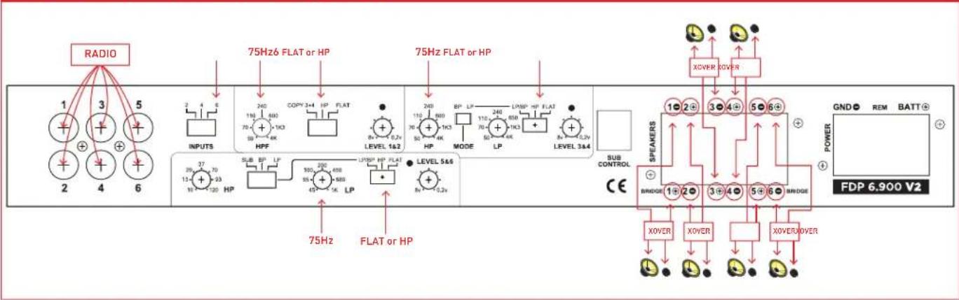
6 CHANNEL STEREO NON-BRIDGED (SEE GRAPHIC C1 ON PG 3)
- If you have two input wires from the source deck plug them into inputs 1+2. Set INPUT switch to 2.
- If you have four input wires from the source deck plug them into inputs 1+2 and 3+4. Set INPUT switch to 4.
- If you have five input wires from the source deck plug them into inputs 1+2 and 3+4. The subwoofer plugs into channel 5. Set channel 5+6 MODE switch to SUB. Set INPUT switch to 6.
- If you have six input wires from the source deck plug them into inputs 1+2, 3+4, 5+6. Set INPUT switch to 6.
- If you are NOT using a subwoofer set all switches to flat. If you hear distortion in your woofers set all switch to HP and adjust all HP frequency until the distortion goes away. This will probably be around 50 Hz to 75 Hz.
C1 (6 CHANNEL STEREO NON-BRIDGED)
flowchart
graph TD
    A["RADIO"] --> B["INPUTS"]
    B --> C["75Hz FLAT or HP"]
    C --> D["75Hz FLAT or HP"]
    D --> E["LEVEL 1&2"]
    E --> F["HP"]
    F --> G["MODE"]
    G --> H["LP"]
    H --> I["LEVEL 3&4"]
    I --> J["SUB CONTROL CE"]
    J --> K["BRIDGE"]
    K --> L["XOVER"]
    K --> M["XOVER"]
    K --> N["XOVER/OVER"]
    L --> O["POWER FDP 6.900 V2"]
    M --> O
    N --> O
    style A fill:#f9f,stroke:#333
    style O fill:#ccf,stroke:#333
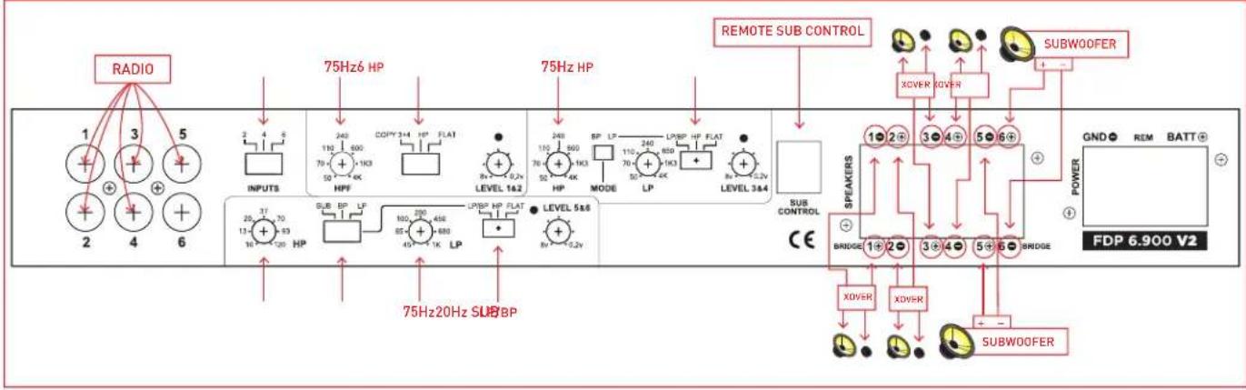
IF YOU ARE USING TWO SUBWOOFERS (SEE GRAPHIC C2 BELOW)
- Put your woofer/tweeters on channel 1+2, 3+4.
Set 1+2, 3+4 switch to HP.
Adjust 1+2, 3+4 HP frequency to 75 Hz.
- Subwoofers on channel 5+6.
Set channel 5+6 switch to LP/BP.
Set channel 5+6 MODE switch to SUB.
Plug in the remote sub control.
Adjust the 5+6 LP frequency to 75 Hz.
For a sealed box adjust the 5+6 HP frequency to 20 Hz.
For a vented box adjust the 5+6 HP frequency 5 Hz lower than the port tune frequency.
C2 (IF YOU ARE USING TWO SUBWOOFERS)
flowchart
graph TD
    A["1"] --> B["INPUTS"]
    C["3"] --> D["75Hz HP"]
    E["5"] --> F["75Hz HP"]
    G["2"] --> H["INPUTS"]
    I["4"] --> J["75Hz HP"]
    K["6"] --> L["75Hz HP"]
    M["75Hz 20Hz SUB BP"] --> N["LEVEL 14.2"]
    O["75Hz 20Hz SUB BP"] --> P["LEVEL 5.8"]
    Q["75Hz 20Hz SUB BP"] --> R["LEVEL 3.4"]
    S["RADIO"] --> T["INPUTS"]
    U["RADIO"] --> V["OUTPUTS"]
    W["REMOTE SUB CONTROL"] --> X["POWER"]
    Y["SUBWOOFER"] --> Z["SUBWDER"]
    AA["SUBWOOFER"] --> AB["SUBWDER"]
    AC["SUBWOOFER"] --> AD["SUBWDER"]
    AE["SUBWOOFER"] --> AF["SUBWDER"]
    AG["SUBWOOFER"] --> AH["SUBWDER"]
    AI["SUBWOOFER"] --> AJ["SUBWDER"]
    AK["SUBWOOFER"] --> AL["SUBWDER"]
    AM["SUBWOOFER"] --> AN["SUBWDER"]
    AO["SUBWOOFER"] --> AP["SUBWDER"]
    AQ["SUBWOOFER"] --> AR["SUBWDER"]
    AS["SUBWOOFER"] --> AT["SUBWDER"]
    AU["SUBWOOFER"] --> AV["SUBWDER"]
    AW["SUBWOOFER"] --> AX["SUBWDER"]
    AY["SUBWOOFER"] --> AZ["SUBWDER"]
    BA["XOVER"] --> BB["XOVER"]
    BC["XOVER"] --> BD["XOVER"]
    BE["XOVER"] --> BF["XOVER"]
    BG["XOVER"] --> BH["XOVER"]
    BI["XOVER"] --> BJ["XOVER"]
    BK["XOVER"] --> BL["XOVER"]
    BM["XOVER"] --> BN["XOVER"]
    BO["XOVER"] --> BP["XOVER"]
    BP["XOVER"] --> BQ["XOVER"]
    BR["XOVER"] --> BS["XOVER"]
    BT["XOVER"] --> BU["XOVER"]
    BV["XOVER"] --> BW["XOVER"]
    BX["XOVER"] --> BY["XOVER"]
    BZ["XOVER"] --> BQ
    CC["XOVER"] --> BQ
    DD["XOVER"] --> BE
    EE["XOVER"] --> BF
    BF["XOVER"] --> BG
    BG["XOVER"] --> BH
    BH["XOVER"] --> BI
    BI["XOVER"] --> BJ
    BJ["XOVER"] --> BK
    BK["XOVER"] --> BL
    BL["XOVER"] --> BN
    BN["XOVER"] --> BO
    BO["XOVER"] --> BB
    BB["XOVER"] --> BC
    BC["XOVER"] --> BT
    BT["XOVER"] --> BI
    BI["XOVER"] --> BJ
    BJ["XOVER"] --> BK
    BK["XOVER"] --> BL
    BL["XOVER"] --> BN
    BN["XOVER"] --> BO
    BO["XOVER"] --> BB
    BB["XOVER"] --> BC
    BC["XOVER"] --> BT
    BT["XOVER"] --> BI
    BI["XOVER"] --> BJ
    BJ["XOVER"] --> BK
    BK["XOVER"] <--> BL
    BL["XOVER"] <--> BN
    style A fill:#f9f,stroke:#333
    style B fill:#ccf,stroke:#333
    style C fill:#cfc,stroke:#333
    style D fill:#fcc,stroke:#333
    style E fill:#cff,stroke:#333
    style F fill:#ffc,stroke:#333
    style G fill:#fcc,stroke:#333
    style H fill:#ffc,stroke:#333
    style I fill:#fcc,stroke:#333
    style J fill:#fcc,stroke:#333
    style K fill:#fcc,stroke:#333
    style L fill:#fcc,stroke:#333
    style M fill:#fcc,stroke:#333
    style N fill:#fcc,stroke:#333
    style O fill:#fcc,stroke:#333
    style P fill:#fcc,stroke:#333
    style Q fill:#fcc,stroke:#333
    style R fill:#fcc,stroke:#333
    style S fill:#fcc,stroke:#333
    style T fill:#fcc,stroke:#333
    style U fill:#fcc,stroke:#333
    style V fill:#fcc,stroke:#333
    style W fill:#fcc,stroke:#333
    style X fill:#fcc,stroke:#333
    style Y fill:#fcc,stroke:#333
    style Z fill:#fcc,stroke:#333
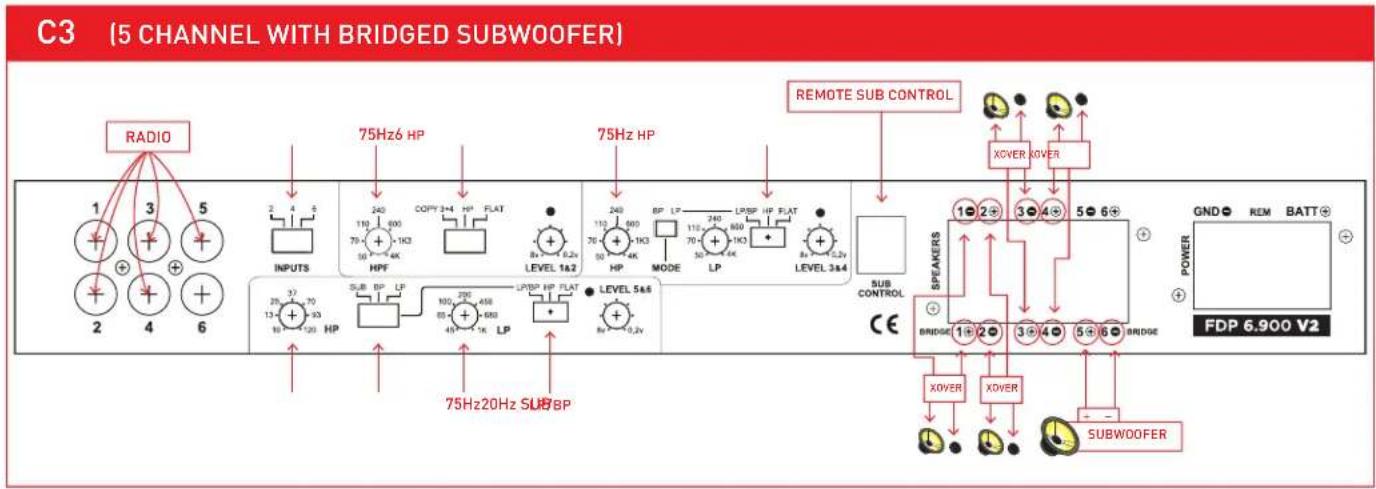
5 CHANNEL WITH BRIDGED SUBWOOFER (SEE GRAPHIC C3 ON PG 4)
- If you have two input wires from the source deck plug them into inputs 1+2. Set INPUT switch to 2.
- If you have four input wires from the source deck plug them into inputs 1+2 and 3+4. Set INPUT switch to 4.
- If you have five input wires from the source deck plug them into inputs 1+2 and 3+4. The subwoofer plugs into channel 5. Set channel 5+6 MODE switch to SUB. Set INPUT switch to 6.
- If you have six input wires from the source deck plug them into inputs 1+2, 3+4, 5+6. Set INPUT switch to 6.
- Put your woofer/tweeters on channel 1+2, 3+4. Set 1+2, 3+4 switch to HP. Adjust 1+2, 3+4 HP frequency to 75 Hz.
- One 4ohm subwoofer bridged mono is wired to channel 5+ and channel 6-. * Do NOT use a 2ohm subwoofer.
Set channel 5+6 switch to LP/BP. Set channel 5+6 MODE switch to SUB.
Plug in the remote sub control. Adjust the 5+6 LP frequency to 75 Hz.
For a sealed box adjust the 5+6 HP frequency to 20 Hz.
For a vented box adjust the 5+6 HP frequency 5 Hz lower than the port tune frequency.
flowchart
graph TD
    A["1"] --> B["INPUTS"]
    C["2"] --> D["SUB HP"]
    E["3"] --> F["75Hz 6 HP"]
    G["4"] --> H["75Hz 20Hz SUB BP"]
    I["5"] --> J["75Hz 6 HP"]
    K["6"] --> L["LEVEL 1a2"]
    M["75Hz 6 HP"] --> N["CAPY 3x4 HP FLAT"]
    O["8x 6.2v LEVEL 1a2"] --> P["LEVEL 5a4"]
    Q["90HP"] --> R["LPBP HP FLAT"]
    S["100HP FLAT"] --> T["LPBP HP FLAT"]
    U["110HP FLAT"] --> V["LPBP HP FLAT"]
    W["120HP FLAT"] --> X["LEVEL 3a4"]
    Y["130HP FLAT"] --> Z["LEVEL 5a4"]
    AA["140HP FLAT"] --> AB["LEVEL 3a4"]
    AC["150HP FLAT"] --> AD["LEVEL 5a4"]
    AE["160HP FLAT"] --> AF["LEVEL 3a4"]
    AG["170HP FLAT"] --> AH["LEVEL 5a4"]
    AI["180HP FLAT"] --> AJ["LEVEL 3a4"]
    AK["190HP FLAT"] --> AL["LEVEL 5a4"]
    AM["200HP FLAT"] --> AN["LEVEL 3a4"]
    AO["210HP FLAT"] --> AP["LEVEL 5a4"]
    AQ["220HP FLAT"] --> AR["LEVEL 3a4"]
    AS["230HP FLAT"] --> AT["LEVEL 5a4"]
    AU["240HP FLAT"] --> AV["LEVEL 3a4"]
    AW["250HP FLAT"] --> AX["LEVEL 5a4"]
    AY["RESMOTE SUB CONTROL"] --> AZ["XOVER XOVER"]
    BA["SUB CONTROL"] --> BB["XOVER"]
    BC["SUB WOOFER"] --> BD["XOVER"]
    BE["SUEKERS"] --> BF["XOVER"]
    BG["GND REM BATT"] --> BH["FDP 6,900 V2"]
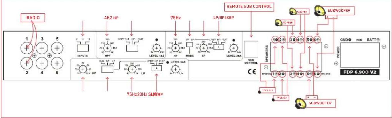
TRIAMP A SUBWOOFER, WOOFER, AND TWEETER (SEE GRAPHIC C4 ON PG 5)
- Connect the source deck front channel wires into inputs 1+2. Set INPUTS switch to 1+2.
- Connect your tweeters to channels 1+2. Set 1+2 switch to HP. Adjust 1+2 HP frequency to the tweeter manufactures recommendation. 4 kHz is a good starting point.
- Connect your woofers to channels 3+4. Set channel 3+4 switch to LP/BP. Set channel 3+4 switch to BP. Adjust the 3+4 LP frequency to the manufactures recommendation. 4 kHz is a good starting point. Adjust 3+4 HP frequency to 75 Hz.
- If you have two subwoofers connect one to channel 5 and one to channel 6. - If you have one 4ohm subwoofer connect it to channel 5+ and channel 6- . Do NOT use a 2ohm subwoofer.
- Set channel 5+6 switch to LP/BP. Set channel 5+6 MODE switch to SUB. Plug in the remote sub control. Adjust the 5+6 LP frequency to 75 Hz. For a sealed box adjust the 5+6 HP frequency to 20 Hz. For a vented box adjust the 5+6 HP frequency 5 Hz lower than the port tune frequency.
C4 (TRIAMP A SUBWOOFER, WOOFER, AND TWEETER)
text_image
RADIO 1 3 5 + + + + + + 2 4 6 INPUTS 4K2 HP 240 110 500 70 + 1K3 50 + 4K COMP 3+4 HP FLAT 8x 0.2x LEVEL 1.6.2 75Hz 240 110 400 70 + 1K3 50 + 4K LP/BP 4KBP 3F LP 110 400 70 + 1K3 50 + 4K LP/BP HP FLAT 8x 5.2x LEVEL 3&4 REMOTE SUB CONTROL W30FER SUBWOOFER W30FER POWER GND REM BATT+ FDP 6.900 V2 1 2 3 4 5 6 + SEAKERS BRIDGE 1+2-3+4-5-6- TWEETER TWEETER SUBWOOFER CE3 CHANNEL BRIDGED (SEE GRAPHIC C5 BELOW)
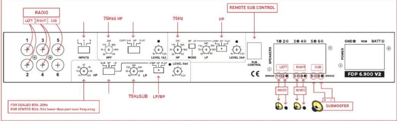
- Set INPUT switch to 6
Connect Front Left Channel from Source unit with Y adapter to input 1+2
Connect Front Right Channel from Source unit with Y adapter to input 3+4
Connect Sub output from you Source unit to input 5. If your source only has single output, use a Y adapter.
If you don't have a Subwoofer output, then move the INPUT switch to 4
- Connect Left Speaker to (1+, 2-)
Connect Right Speaker to (3+,4-)
Connect Subwoofer to (5+,6-)
Set channel 1+2 and channel 3+4 to HP
The LEVEL control on channel 1+2 and channel 3+4 need to be set identically
- Adjust channel 1+2 HPF to 70 Hz
Adjust channel 3+4 HP to 70 Hz
Set channel 5+6 Crossover Switch to LP/BP and Sub
Adjust channel 5+6 LP to 70 Hz
For a sealed box, adjust channel 5+6 HP to 20 Hz
For a vented box, adjust channel 5+6 HP to 5 Hz below port tuning frequency
C5 (3 CHANNEL BRIDGED)
text_image
RADIO LEFT RIGHT SUB 1 3 5 2 4 6 75Hz6 HP INPUTS 2 4 8 HPF 240 110 600 70+ 1K3 50+ 4K COPY 3+4 HP FLAT 8x-1 0.2v LEVEL 1&2 75Hz HP 240 110 600 70+ 1K3 50+ 4K MODE 110 240 70+ 1K3 50+ 4K LPBP HP FLAT 8x-1 0.2v LEVEL 3&4 SUB CONTROL CE 75HzSUB LP/BP SPEAKERS 1●2●3●4●5●6+ LEFT RIGHT SUB BRIDGE 1●2●3●4●5●6 BRIDGE POWER GND● REM BATT+ FDP 6.900 V2 FOR SEALED BOX: 20Hz FOR VENTED BOX: 5Hz lower than port tune frequency XOVER XOVER + SUBWOOFERPOWER FUSES & BALANCED/UNBALANCED SWITCHES
POWER FUSES
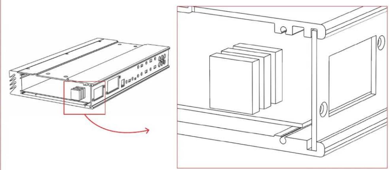
natural_image
Technical line drawing of an electronic device housing with internal components and mounting brackets (no text or symbols)→ TO USE: Remove the end panel by the power terminals
3 x 25 amp ATC fuse
You should have an 80 AMP fuse at the battery.
BALANCED/UNBALANCED SWITCHES
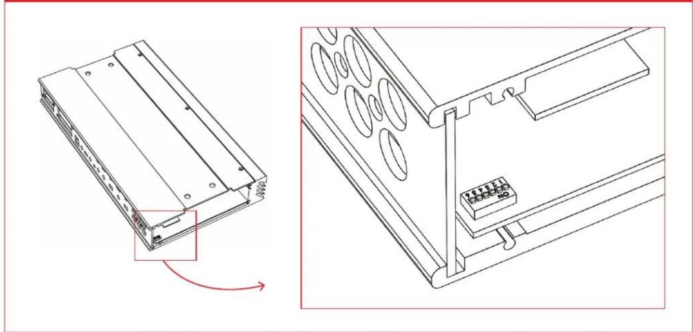
natural_image
Technical line drawing of an electronic device showing a component with a red arrow indicating rotation (no text or symbols present)→ TO USE: Remove the end panel by the RCA jacks.
The standard switch position is input ground "ON".
Flip the switch "OFF" changes the input to "balanced input floating ground".
To flip the switch, use a small pick or jewelers screw driver.
TROUBLESHOOTING
→ FOCAL SIGN DOES NOT LIGHT
- Measure the voltage at the amplifier power terminal. It should be between 12.5 and 15 volts.
- Measure the voltage at the amplifier REM terminal. It should be between 12 and 15 volts.
- If you are using BTL high level for automatic turn on, try connecting a REM wire.
- Check your power and ground connections to be correct polarity + and - and they are clean and tight.
- Check battery connections.
- Check the fuse in the REM wire.
- Check 80 AMP fuse at battery.
- Check fuse inside amplifier. The fuse is inside the right end cap beside the power terminals. The recommended ATC fuse size is three 25 amp.
-
Is the amp very hot?
Wait a few minutes for it to cool down. You need to get more fresh cool air to the amplifier. Do not cover the amplifier or mount it flush into a hole. -
If the amp is cold and the Focal sign is flashing, there is an internal fault. The amplifier must then be returned for service.
→ NO SOUND
- Is the Focal sign light off or flashing?
- Is the source radio on and is there a sound signal coming from the source radio?
- Use an ohm meter and measure the speaker wires for short circuit.
- Check connections for small "wire whisker" that may be shorting between amplifier terminals or speaker terminals.
- Use an ohm meter and measure the speaker for short circuit.
- Double check your connections to the source radio.
- Are you using the correct source radio wires and are they plugged into the correct amplifier RCA?
- Double check your connections to the speakers and speaker crossovers.
- Check that all amplifier switches are in the correct positions for your speaker set up.
- Check that HP & LP frequencies are set correctly for your speakers.
- If little or no sound, make sure that you are NOT in BP (Band Pass) Mode, with the crossover points overlapping or HP/LP frequency reversed.
→ AMPLIFIER BLOWS FUSE WHEN YOU TURN IT ON
- Power and ground may be reversed.
Check + and - polarity at amplifier and at battery.
→ SUBWOOFER REMOTE VOLUME CONTROL DOES NOT FUNCTION
- Check that Remote Volume Control wire is plugged into the amplifier securely.
→ SUBWOOFER REMOTE VOLUME CONTROL LED LIGHT
- While playing music the LED light should be Green.
Occasional red LED light flash indicates that the amplifier has reached maximum loudness and has distortion.
- If the red LED light flashes with the beat of the music,
TURN DOWN THE VOLUME before you damage your speaker.
- If the red LED light is on continuous,
TURN DOWN THE VOLUME before you blow up your speaker.
WARRANTY INFORMATION
Focal America / Orca Design & Manufacturing supports their products and guarantees them to be free of manufacturing defects for a period of 1 year (non-transferrable) from the date of purchase, if purchased from and authorized retailer. This time period is extended to 3 years (non-transferrable) from the date of purchase, if the amplifier is purchased from and installed by an authorized retailer, and no alterations are made to the installation or setup of the amplifier outside of the authorized retailer.
This manufacturing warranty does not extend to situations involving physical or installation damage, misuse, abuse, or modification. If an amplifier malfunctions, please return it to the authorized retailer from which the amplifier was purchased to have the amplifier and/or installation inspected and to have the warranty period verified from date of purchase.
The authorized dealer will then work with Focal America / Orca Design & Manufacturing to obtain service, if necessary. If found to be a defect due to manufacturing, the item will be repaired or replaced with a refurbished amplifier. The amplifier will be returned to the authorized retailer when repairs are complete, so that the dealer can return the amplifier to you, or reinstall the amplifier to maintain the above mentioned warranty timeline.
TECHNICAL SPECIFICATIONS
6 x 150w RMS into 4 ohms @ 1% THD
6 x 200w RMS into 2 ohms @ 1% THD
4 x 150w RMS into 4 ohms + 1 x 500w RMS into 4 ohms (Ch 5+6 Bridged) @ 1% THD
4 x 200w RMS into 2 ohms + 1 x 500w RMS into 4 ohms (Ch 5+6 Bridged) @ 1% THD
Do NOT bridge into 2 ohms.
All power ratings are at 14.4v DC.
Frequency Response 5 Hz to 25 kHz.
S/N ratio 90 dB
RCA input can use a BTL source or common ground source.
RCA switch select balanced floating ground or grounded to minimize noise.
Input sensitivity 200mV to 10 volts
Slew Rate 13 V / uS
Each input has a peak limiter to prevent severe distortion and speaker damage. It allows light clipping.
Each channel has variable high pass crossover: 50 Hz to 4000 Hz, 12 dB Linkwitz-Riley
Each channel has variable low pass crossover: 50 Hz to 4000 Hz, 12 dB Linkwitz-Riley
Each channel has variable band pass crossover: 50 Hz to 4000 Hz, 12 dB Linkwitz-Riley
Channels 5, 6 in bridged subwoofer mode, 24 dB Linkwitz-Riley
Subwoofer remote volume control includes a clipping indicator light. Recommended DC voltage operating range 11.5 to 14.4 volts.
Minimum DC voltage operating range 8 to 16 volts.
Install an 80 AMP fuse at the battery.
Dimensions: 7 3/4" (196mm) x 14 3/8" (364mm) x 2" (50mm)
Weight: 8 pounds