AC1200 - Router TP-LINK - Free user manual and instructions
Find the device manual for free AC1200 TP-LINK in PDF.

User questions about AC1200 TP-LINK
0 question about this device. Answer the ones you know or ask your own.
Ask a new question about this device
Download the instructions for your Router in PDF format for free! Find your manual AC1200 - TP-LINK and take your electronic device back in hand. On this page are published all the documents necessary for the use of your device. AC1200 by TP-LINK.
USER MANUAL AC1200 TP-LINK
Note: Images may differ from your actual product
Network Topology
A typical network topology for the AP is shown below
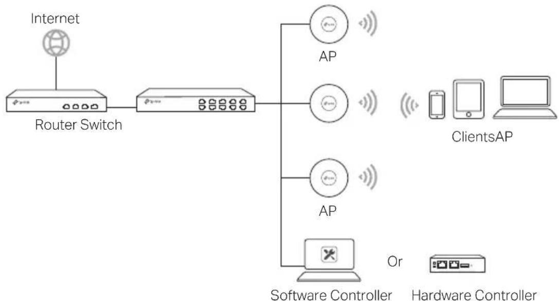
APs can be centrally configured and monitored via Controller You can get the Controller from https://www.tp-link.com or contact the sales staff
Hardware Installation
Option 1: Ceiling Mounting
Follow the steps below to install the AP with the provided accessories:
Note: The mounting bracket and the accessories (quantity and size) may vary by product

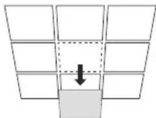
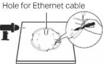
1 Remove the ceiling tile
English
2
Place the mounting bracket in the center of the ceiling tile. Mark positions for the screw holes and a position for the Ethernet cable hole Drill 4mm diameter holes for the so and a 25~mm diameter hole for the Ethernet cable at the marked positions
3
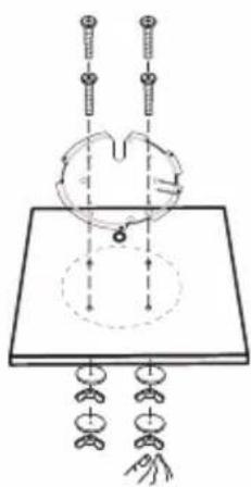
Secure the mounting bracket to the ceiling tile using pan-head screws, washers and wing nuts
4
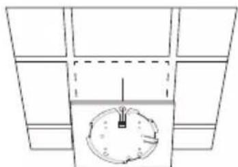
Feed the Ethernet cable through the hole and set the ceiling tile back into place
5
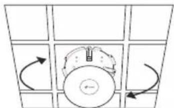
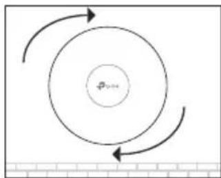
Connect the Ethernet cable to the Ethernet port Attach the AP to the mounting bracket by aligning the arrow mark on the AP with the arrow mark on the mounting bracket, then rotate the AP until it is locked into place
Option 2: Wall Mounting
Follow the steps below to install the AP with the provided accessories: Note: The mounting bracket and the accessories (quantity and size) may vary by product
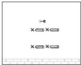
Plastic Wall Anchors Self-tapping Screws
1
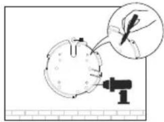
If your Ethernet cable feeds through the wall, position the mounting bracket and feed the Ethernet cable Mark positions for the screw holes and then drill 6 mm diameter holes at the marked positions
2
Insert the plastic wall anchors into the 6 mm diameter holes
3
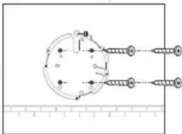
Secure the mounting bracket to the wall by driving the self-tapping screws into the anchors Make sure that the shoulders of the mounting bracket are on the outside
4
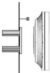
Connect the Ethernet cable to the Ethernet port on the AP
5
Attach the AP to the mounting bracket by aligning the arrow mark on the AP with the arrow mark on the mounting bracket, then rotate the AP until it is locked into place
Power Supply
Power via PSE Device or Power Adapter
Some APs can be powered via the power adapter or the PSE device (such as a PoE switch) which complies with Power Source Class 2 (PS2) or Limited Power Source (LPS) of IEC 62368-1
Note: Availability depends on the actual product Please refer to the product specifications
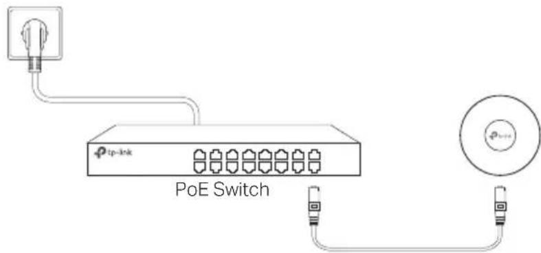
Via PoE Switch
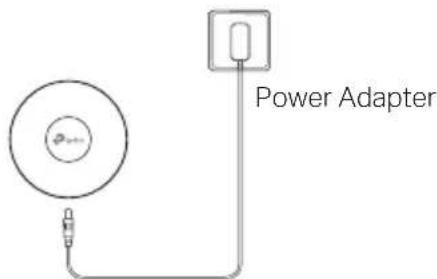
Via Power Adapter
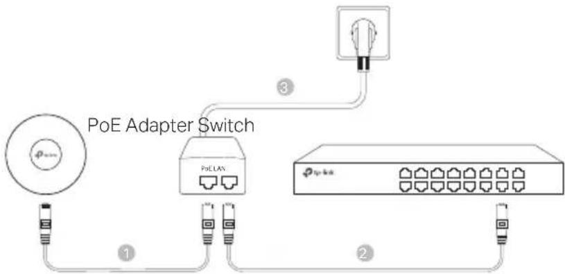
Power via PoE Adapter
Some APs can be powered via the PoE adapter
Note: Availability depends on the actual product
Please refer to the product specifications
For technical support, the user guide and other information, please visit https://wwwtp-linkcom/support/, or simply scan the QR code.