MAG 50 - Drill METABO - Free user manual and instructions
Find the device manual for free MAG 50 METABO in PDF.
| Feature | Details |
|---|---|
| Device type | Drill |
| Power | 500 W |
| No-load speed | 0 - 2,800 rpm |
| Drilling capacity in concrete | 20 mm |
| Drilling capacity in steel | 13 mm |
| Drilling capacity in wood | 30 mm |
| Weight | 1.8 kg |
| Dimensions | 320 x 200 x 80 mm |
| Chuck system | Keyed chuck |
| Usage | Drilling into various materials such as wood, metal, and concrete |
| Maintenance | Regular cleaning and lubrication of moving parts recommended |
| Safety | Wear safety glasses and gloves when using |
| Warranty | 2 years |
Frequently Asked Questions - MAG 50 METABO
Download the instructions for your Drill in PDF format for free! Find your manual MAG 50 - METABO and take your electronic device back in hand. On this page are published all the documents necessary for the use of your device. MAG 50 by METABO.
USER MANUAL MAG 50 METABO
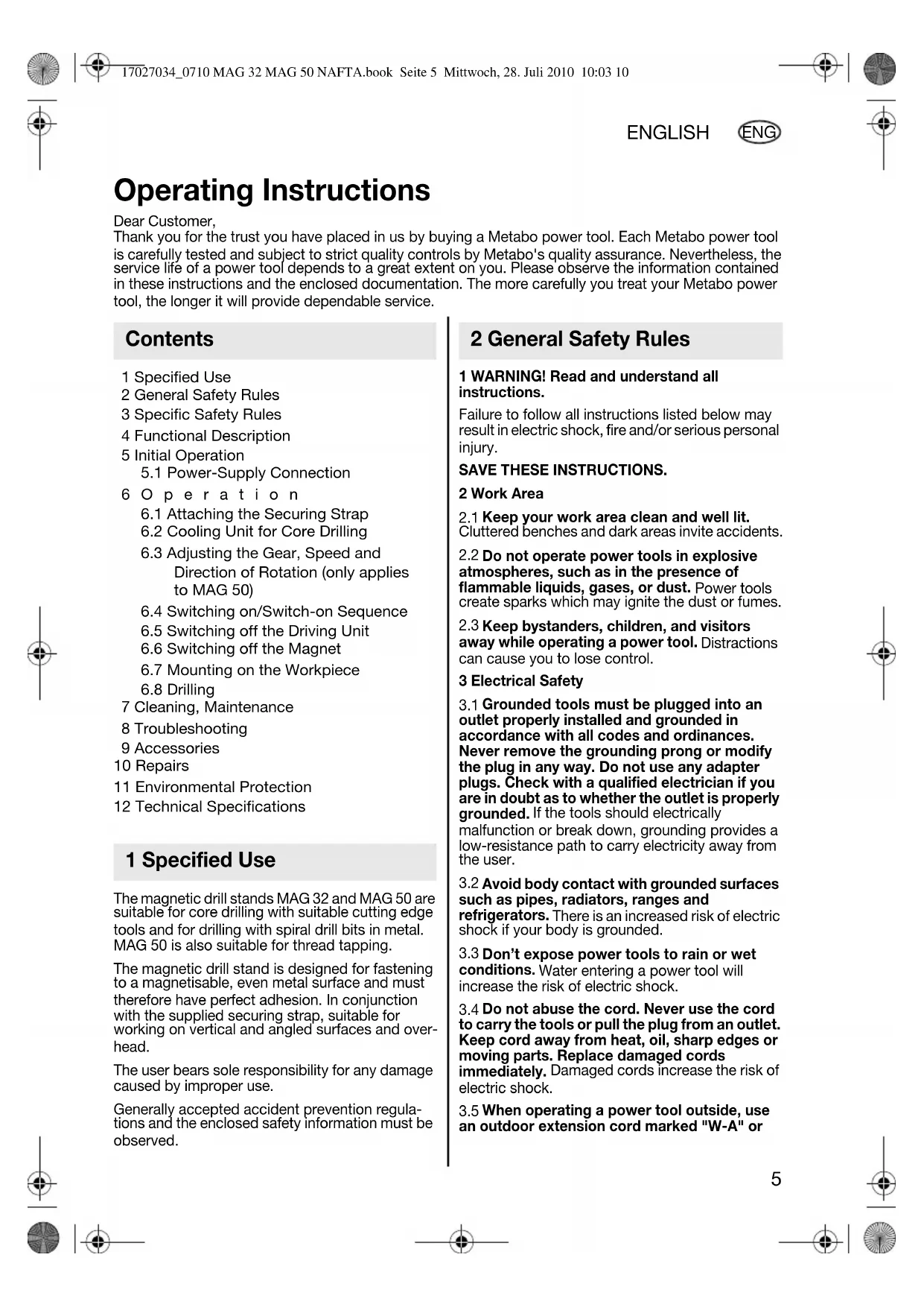
ENG 1 Specified Use 2 General Safety Rules 3 Specific Safety Rules 4 Functional Description 5 Initial Operation
6.1 Attaching the Securing Strap
6.2 Cooling Unit for Core Drilling
6.3 Adjusting the Gear, Speed and
Direction of Rotation (only applies to MAG 50)
6.4 Switching on/Switch-on Sequence
6.5 Switching off the Driving Unit
6.6 Switching off the Magnet
6.7 Mounting on the Workpiece
7 Cleaning, Maintenance 8 Troubleshooting 9 Accessories 10 Repairs 11 Environmental Protection 12 Technical Specifications The magnetic drill stands MAG 32 and MAG 50 are suitable for core drilling with suitable cutting edge tools and for drilling with spiral drill bits in metal. MAG 50 is also suitable for thread tapping. The magnetic drill stand is designed for fastening to a magnetisable, even metal surface and must therefore have perfect adhesion. In conjunction with the supplied securing strap, suitable for working on vertical and angled surfaces and over- head. The user bears sole responsibility for any damage caused by improper use. Generally accepted accident prevention regula- tions and the enclosed safety information must be observed. 1 WARNING! Read and understand all instructions. Failure to follow all instructions listed below may result in electric shock, fire and/or serious personal injury. SAVE THESE INSTRUCTIONS. 2 Work Area
Keep your work area clean and well lit. Cluttered benches and dark areas invite accidents.
Do not operate power tools in explosive atmospheres, such as in the presence of flammable liquids, gases, or dust. Power tools create sparks which may ignite the dust or fumes.
Keep bystanders, children, and visitors away while operating a power tool. Distractions can cause you to lose control. 3 Electrical Safety
Grounded tools must be plugged into an outlet properly installed and grounded in accordance with all codes and ordinances. Never remove the grounding prong or modify the plug in any way. Do not use any adapter plugs. Check with a qualified electrician if you are in doubt as to whether the outlet is properly grounded. If the tools should electrically malfunction or break down, grounding provides a low-resistance path to carry electricity away from the user.
Avoid body contact with grounded surfaces such as pipes, radiators, ranges and refrigerators. There is an increased risk of electric shock if your body is grounded.
Don’t expose power tools to rain or wet conditions. Water entering a power tool will increase the risk of electric shock.
Do not abuse the cord. Never use the cord to carry the tools or pull the plug from an outlet. Keep cord away from heat, oil, sharp edges or moving parts. Replace damaged cords immediately. Damaged cords increase the risk of electric shock.
When operating a power tool outside, use an outdoor extension cord marked "W-A" or Operating Instructions Dear Customer, Thank you for the trust you have placed in us by buying a Metabo power tool. Each Metabo power tool is carefully tested and subject to strict quality controls by Metabo's quality assurance. Nevertheless, the service life of a power tool depends to a great extent on you. Please observe the information contained in these instructions and the enclosed documentation. The more carefully you treat your Metabo power tool, the longer it will provide dependable service. Contents 1 Specified Use 2 General Safety Rules 17027034_0710 MAG 32 MAG 50 NAFTA.book Seite 5 Mittwoch, 28. Juli 2010 10:03 106 ENGLISH ENG "W". These cords are rated for outdoor use and reduce the risk of electric shock. 4 Personal Safety
Stay alert, watch what you are doing and use common sense when operating a power tool. Do not use tool while tired or under the influence of drugs, alcohol or medication.
moment of inattention when operating power tools may result in serious personal injury.
Dress properly. Do not wear loose clothing or jewelry. Contain long hair. Keep your hair, clothing and gloves away from moving parts. Loose clothes, jewelry or long hair can be caught in moving parts.
Avoid accidental starting. Be sure switch is off before plugging in. Carrying tools with your finger on the switch or plugging in tools that have the switch on invites accidents.
Remove adjusting keys or wrenches before turning the tool on. A wrench or a key that is left attached to a rotating part of the tool may result in personal injury.
Do not overreach. Keep proper footing and balance at all times. Proper footing and balance enable better control of the tool in unexpected situations.
Use safety equipment. Always wear eye protection. Dust mask, non-skid safety shoes, hard hat or hearing protection must be used for appropriate conditions.
Use clamps or other practical way to secure and support the workpiece to a stable platform. Holding the work by hand or against your body is unstable and may lead to loss of control.
Do not force tool. Use the correct tool for your application. The correct tool will do the job better and safer at the rate for which it is designed.
Do not use tool if switch does not turn it on or off. Any tool that cannot be controlled with the switch is dangerous and must be repaired.
Disconnect the plug from the power source before making any adjustments, changing accessories, or storing the tool. Such preventive safety measures reduce the risk of starting the tool accidentally.
Store idle tools out of reach of children and other untrained persons. Tools are dangerous in the hands of untrained users.
Maintain tools with care. Keep cutting tools sharp and clean. Properly maintained tools with sharp cutting edges are less likely to bind and are easier to control.
Check for misalignment or binding of moving parts, breakage of parts, and any other condition that may affect the tool's operation. If damaged, have the tool serviced before using. Many accidents are caused by poorly maintained tools.
Use only accessories that are recommended by the manufacturer for your model. Accessories that may be suitable for one tool may become hazardous when used on another tool. 6 Service
Tool service must be performed only by qualified repair personnel. Service or maintenance performed by unqualified personnel could result in a risk of injury.
When servicing a tool, use only identical replacement parts. Follow instructions in the Maintenance section of this manual. Use of unauthorized parts or failure to follow Maintenance instructions may create a risk of electric shock or injury. Always use securing strap
Mounting can release. WARNING – Reading the operating instructions will reduce the risk of injury. For your own protection and for the protection of your power tool pay atten- tion to all parts of the text that are marked with this symbol! For work carried out on angled and vertical surfaces and overhead, the magnetic drill stand must be secured with the securing strap supplied to prevent it from falling if the power supply is interrupted. When the magnet is switched off, or if the power supply is interrupted, the magnet loses it holding power. The machine executes a dangerous swinging movement. Always wear a hard hat when working overhead. Always wear protective goggles, gloves, and suit- able shoes when working. Ensure there is no damage to the mains connec- tion cables, switch and anti-kink device. The magnet produces magnetic and electromag- netic fields that can have a negative effect on medical implants. The surface for the electromagnet must be clean and flat. The magnet holding power depends on material thickness and condition. Paint, zinc and oxide layers reduce the magnet holding power. 3 Specific Safety Rules 17027034_0710 MAG 32 MAG 50 NAFTA.book Seite 6 Mittwoch, 28. Juli 2010 10:03 10ENGLISH
ENG Do not expose the machine to rain and do not use in wet or potentially explosive rooms. Disconnect the mains plug from the plug socket before performing any adjustments or mainte- nance on the machine. Caution! When you unplug the mains plug, the magnet loses its holding power. If (after use) the magnetic drill stand is placed on a material with low heat-dissipation characteristics for a long period (e.g. plastic), the magnet must not be switched on because this could lead to over- heating of the magnetic coils. Follow the instructions for lubrication and tool replacement. Keep the handles dry, clean and free of oil and grease. Caution! The use of other tools and accessories can result in a risk of injury. Use the handle (4) on the magnetic drill stand when transporting the machine. Always wear a safety harness when working on scaffolds. Wear ear protectors. Wear protective goggles. Danger - electrical voltage. Danger - magnetic field. Persons with pacemakers prohibited. Symbols on the tool: V............... volts A............... amperes W.............. watt Hz............. hertz .../min....... revolutions per minute ~...............alternating current
.............no load speed See page 3 (please unfold). 1Securing strap 2 Ratchet on securing strap 3 Two holding points 4Handle 5 Container for cooling lubrication unit 6 Supply cock on cooling lubrication unit 7 Threaded pins for adjusting backlash of the side plate 8 Thumbwheel (1st /2nd gear) * 9 Slot in machine neck for driving out tools * 10 Removal tool * 11 Drill spindle with tool attachment (MK 2) * 12 Setting wheel (speed adjustment) * 13 Electronic signal indicator* 14 Slide plate 15 Lever for moving driving unit up and down 16 Switch (switching on driving unit) 17 Switch (switching off driving unit) 18 Switch (switching on/off magnet) 19 Switch (direction of rotation) * 20 Magnet block/Magnet 21 Tool holder threaded pins* 22 Tool holder (Weldon, 19 mm) * 23 Anti-twist device*
- depending on fittings/model Before plugging in, check that the rated mains voltage and mains frequency, as stated on the rating label, match with your power supply. Check the machine for possible damage: Before using the machine, you must carefully check protective devices or slightly damaged components to ensure they are operating perfectly and as intended. Check that moving parts are in perfect working order and do not jam and check whether parts are damaged. All parts must be correctly installed and fulfil all conditions neces- sary to ensure the perfect operation of the machine. Damaged protective devices and parts must be repaired or replaced according to specifi- cations by an authorised specialist workshop.
5.1 Power-Supply Connection
The machine is in protection class I and must therefore only be connected to sockets earthed according to specifications. Regularly check the power cable on the power tool and have it repaired by an approved expert if damaged. If an extension cord is needed, it must be a three- core lead with a protective (earth) contactor that is properly connected to both the plug and the coupler of the cord. 4 Functional Description 5 Initial Operation 17027034_0710 MAG 32 MAG 50 NAFTA.book Seite 7 Mittwoch, 28. Juli 2010 10:03 108 ENGLISH ENG When working outdoors, only use the correspond- ingly marked extension cable approved for this purpose. Regularly check extension cables and replace if damaged. Extension cables must be suitable for the driving unit and magnetic drill stand power ratings (see Technical Specifications). If using a roll of cable, always roll up the cable completely.
6.1 Attaching the Securing Strap
For drilling work carried out on angled and vertical surfaces and overhead, the magnetic drill must be secured with the securing strap (1) supplied to prevent it from falling if the power supply is interrupted. Fit the securing strap (1) so that the magnetic drill stand is moved away from the operator
the mains voltage fails. Replace the securing strap (1) if it has had to catch a falling magnetic drill stand. Caution! Check the securing strap (1) for damage. Before using the securing strap (1), always check it carefully to ensure it is operating faultlessly and as specified. If the securing strap (1) is damaged or if the ratchet (2) is no longer working properly, replace the securing strap immediately. -Fit the securing strap (1) on one of the two holding points (3) of the magnetic drill stand. - Then secure the securing strap to another suit- able fastening point or to the material being processed. - Notes on the securing strap (1): Insert the free end of the securing strap (1) from below through the opening in the ratchet shaft and then tension the free end of the securing strap until it is loosely fitted. The strap must not be tightly fitted: you must be able to unroll the securing strap
more than one rotation about the ratchet shaft
This is essential to ensure secure fastening. Tension the securing strap with a pumping action on the ratchet lever (a). To loosen the securing strap: Caution: the tension is released in sudden bursts! To loosen the securing strap , open the ratchet fully and simultaneously use your finger to pull the locking strap (b) upward. - Ensure that the securing strap is guided to be taut in position. - Check that the strap connection is secure. The securing strap does not replace the magnetic force of the magnetic drill stand: it is simply used to secure against falling in the event of a voltage failure.
6.2 Cooling Unit for Core Drilling
The tool life depends on the lubrication. Lubri- cating the inside of the core drill bit with high- performance cutting oils is essential for core drilling. To fill with oil, remove the container (5) from the magnetic drill stand. Fill the container with high-performance cutting oil (5) and close the screw cap. Switch the lubrication on or off at the supply cock (6). For work carried out on vertical and overhanging surfaces or overhead surfaces, the c ontainer (5) must be emptied or removed to prevent liquid from escaping (otherwise there is a risk of cutting oil entering the motor and causing a short-circuit)
When carrying out this type of task, spray the inside of the cutting edge tool before drilling with universal cutting spray (see chapter 9 Accesso- ries). Repeat the process several times for larger drilling depths.
6.3 Adjusting the Gear, Speed and Direc-
tion of Rotation (only applies to MAG 50) Two-speed gear box: Do not activate the thumbwheel (8) until the motor has completely stopped. Select the required gear by turning the thum- bwheel (8). If necessary, you can aid the switching procedure by turning the drill spindle slightly. Recommended setting:
= 2nd gear, high speed: Drilling in steel with a bit diameter of up to approx. 26 mm
= 1st gear, high torque: Drilling in steel with a bit diameter larger than approx. 26 mm Setting speed Using the setting wheel, you can adjust the motor speed continuously (12) and thus adapt it to the material and working conditions. Setting the direction of rotation Set the required direction of rotation at the switch (19). 6 Operation
= Clockwise (adjust for drilling)
6.4 Switching on/Switch-on Sequence
For safety reasons, the driving unit can only be switched on after the magnet has been switched on. Please observe the switch-on sequence.
1. First switch on the magnet: set switch (18) to
"I". When the magnet is switched on, the indi- cator lamp built into the switch (18) lights up.
2. Wait until this occurs before turning on the
driving unit at the switch (16). See also chapter 8. Note: The full holding power of the magnet is avail- able when the driving unit is switched on.
6.5 Switching off the Driving Unit
Press switch (17). Wait until the driving unit has come to a complete standstill.
Switching off the Magnet When the magnet is switched off, the magnet loses its holding power. Set switch (18) to "0".
6.7 Mounting on the Workpiece
To permit the magnetic drill stand to adhere prop- erly to material that is to be drilled, the surface must be clean and smooth. Loose rust, dirt or grease must be removed before mounting the magnetic drill stand; any welding beads or surface irregularities must be smoothened. Clean the magnet block as well (20) if necessary. After switching on the magnet, shake the handle (4) of the magnetic drill stand firmly to ensure that it is adhering perfectly to the material. If it is not, then check the condition of the surface of the material and that of the bottom of the magnet block. Clean as necessary and try again. Use on thin steel The unit adheres best to low-carbon steel that is at least 12 mm thick. For drilling a hole into thin steel, a steel plate meas- uring at least 100 x 200 x 12 mm can be secured under the material at the place where the magnetic stand is to be positioned. Non-ferrous metals To drill a hole in non-ferrous metal, the steel plate should be secured on the surface of the material and the magnetic drill stand then placed on the steel plate.
Disconnect the mains plug from the plug socket before performing any adjustments or maintenance on the machine. Caution! When you unplug the mains plug, the magnet loses its holding power. Do not use deformed or damaged tools. Before use, always check tools such as core drills for deformities or damage. Do not use accessories that have not been specified or recommended by Metabo for this machine. The ability to attach the accessory to your machine does not guarantee safe operation. Securing or positioning a tool incorrectly can cause hazardous situations due to parts breaking or being blown off. If a tool is blocked, switch off the driving unit immediately: Press switch (17). Remove the tool from the borehole. General notes: - Centre the position at which the hole is to be drilled. - Align the magnetic drill stand so that the drill bit is above the centre marking. - Switch on the magnet of the magnetic drill stand (set switch (18) to "I".). - Then switch on the driving unit (press switch (16)). - If necessary, switch on the cooling lubrication unit (see chapter 6.2. - Start the drilling operation with minimum feeding force. When the drill bit has started to drill, slightly higher feeding force can be applied. Excessive feeding force leads to premature wear of the drill bit. Ensure that the chip flow is regular - Use a wire hook to remove the chips. - If the bored piece of metal is not automatically ejected from the core drill, remove it using a tool, e.g. with the wire hook. If (after use) the magnetic drill stand is placed on a material with low heat-dissipation char- acteristics for a long period (e.g. plastic), the magnet must not be switched on because this could lead to overheating of the magnetic coils. Special notes for tools with morse taper shank MK2 (only applies to MAG 50): Inserting tool
The tool is only guaranteed to fit perfectly in the drill spindle (11) if the female taper of the drill spindle and the taper shank of the tool are free of dirt and grease. Caution! Never use excessive force to press tools into the female taper of the drill spindle! Always use sharp tools in perfect condition. Switch off the machine. Pull the mains plug from the socket. Caution! When you unplug 17027034_0710 MAG 32 MAG 50 NAFTA.book Seite 9 Mittwoch, 28. Juli 2010 10:03 1010 ENGLISH ENG the mains plug, the magnet loses its holding power. Tools with a taper shank MK2 can be used directly in the female taper of the drill spindle (11). Driving out the tool: Insert the removal tool (10) - with the sloping edge against the tool - in the slot (9) on the machine neck. If the removal tool cannot be inserted through the drill spindle, you should turn the drill spindle (11) slightly by hand. Drive out the tool by knocking lightly on the removal tool with a hammer. (10) Special notes on tools with Weldon shank 19 mm: For MAG 50: First insert the industrial attachment 6.26602 (see chapter 9 Accessories). When inserting the attachment, ensure that the side pin of the industrial attachment engages with the anti-twist device (23). Then connect the hose from the c ooling lubrica- tion unit to the connecting piece on the industrial attachment
- Insert the centring pin (of an appropriate length) into the tool. - Insert the tool in the tool holder (22) so that both surfaces (on the cylindrical part of the tool) are located at the positions of the threaded pins (21). - Guide the tool upwards as far as it will go (against the pressure of the integral spring) and tighten the threaded pins (21) using the Allen key. Removing the tool
- Release the two threaded pins (21). Perform regular maintenance work, cleaning and lubrication. Remove the mains plug from the socket before carrying out any settings, maintenance or repairs. Caution! When you unplug the mains plug, the magnet loses its holding power. For lubricating the rack and pinion that moves the slide plate (14) up and down, a few drops of oil should be applied occasionally to the rack. Coat the sliding surfaces of the slide plate (14) with multi-purpose grease. Backlash of the slide plate The backlash of the side plate is set ex works. The side plate (14) must be adjusted so that it can still be moved freely up and down (when the driving unit is installed), and so that it will remain in any position without the weight of the driving unit pulling it down. If necessary, you can adjust the backlash of the slide plate (14) using the three threaded pins (7): release the counternuts, tighten the threaded pins and fasten the counternuts again. Electronic restart protection (for preventing accidental restarting) If, when the driving unit is switched on, a) the magnet is switched off or b) the power supply is interrupted, the driving unit comes to a standstill. If the magnet is then reactivated or the power supply restored, the driving unit will not restart automatically for safety reasons (electronic restart protection). Switch on the driving unit again at the switch (16) . See also chapter 6.4. Electronic signal indicator (13) for MAG 50 Continuously lit - Overload The motor temperature is too high. Reduce the load on the machine. The machine will stop if the overloading persists. Switch off the machine, switch it back on again and allow to cool down at idle speed. Use only genuine Metabo accessories. If you need any accessories, check with your dealer. The dealer needs to know the exact model of your power tool in order to select the correct accessory. See page 4. A Core drill with 19 mm Weldon shank, HSS/HM B Centring pin, short, HSS: for 30 mm cutting depth HM: for core drill bit diameter 14-17 mm C Centring pin, long, HSS: for 55 mm cutting depth HM: for core drill bit diameter 18-100 mm D Morse taper for chuck with female taper E Key-type chuck with female taper F Metal drill bit G Quick replacement system MK2 on Weldon, 19 mm H Industrial holder MK2 on Weldon, 19 mm I Securing belt with ratchet J Universal cutting spray K Weldon adapter, 19 mm, on thread ½“ x 20 UNF L Geared chuck with thread ½“ x 20 UNF M Adapter Weldon, 19 mm, on Fein Quick In 7 Cleaning, Maintenance 8 Troubleshooting 9 Accessories 17027034_0710 MAG 32 MAG 50 NAFTA.book Seite 10 Mittwoch, 28. Juli 2010 10:03 10ENGLISH
ENG For a complete range of accessories, see www.metabo.com or the main catalogue. Have your power tool repaired by a qualified elec- trician. This power tool complies with the appli- cable safety regulations. Repairs must only be carried out by qualified electricians and using orig- inal spare parts; otherwise the user faces a risk of accidents. Any Metabo power tool in need of repair can be sent to one of the addresses listed in the spare parts list. Please enclose a description of the fault when sending the tool for repairs. Metabo's packaging can be 100% recycled. Scrap power tools and accessories contain large amounts of valuable resources and plastics that can be recycled. These instructions are printed on chlorine-free bleached paper. Explanatory notes on the specifications on page 2. Changes due to technological progress reserved. T = Tool attachment M = Max. torque
max, C = Max. diameter (core drill bit)
max, S = Max. diameter (spiral drill bit)
max, T = max. diameter (tap)
= Speeds at rated load
= Height (incl. motor) with slide plate in bottom position
= Height (incl. motor) with slide plate in top position A = Dimensions of magnetic flux m = Weight without mains cable Wear ear protectors! The technical specifications quoted are subject to tolerances (in compliance with the relevant valid standards). 10 Repairs 11 Environmental Protection 12 Technical Specifications 17027034_0710 MAG 32 MAG 50 NAFTA.book Seite 11 Mittwoch, 28. Juli 2010 10:03 1012 FRANÇAIS