 — Outboard motor — Mode d'emploi PDF")
M26 (2020) - Outboard motor YAMAHA - Free user manual and instructions
Find the device manual for free M26 (2020) YAMAHA in PDF.
User questions about M26 (2020) YAMAHA
0 question about this device. Answer the ones you know or ask your own.
Ask a new question about this device
Download the instructions for your Outboard motor in PDF format for free! Find your manual M26 (2020) - YAMAHA and take your electronic device back in hand. On this page are published all the documents necessary for the use of your device. M26 (2020) by YAMAHA.
USER MANUAL M26 (2020) YAMAHA
OWNER'S INSTRUCTION MANUAL
INSTRUKCJA OBSLUGI WŁAŚCICIELA
INSTRUCTIEBOEKJE
BETRIEBSANLEITUNG
MANUEL DE L'UTILISATEUR
Declaration of Conformity
Name of Engine Manufacturer: Johnson Outdoors Inc.
Address: 1531 E. Madison Ave. Mankato, MN 56002-8129, USA
Name of Authorised Representative: YAMAHA MOTOR EUROPE N.V.
Address: Koolhovenlaan 101. 1119 NC Schiphol-Rijk. The Netherlands
Name of Notified Body(electromagnetic compatiblity): Nebraska Center for Excellence in Electronics (NCEE Labs)
Address: 4740 Discovery Drive. Lincoln. NE 68521-5376. USA
DIRECTIVES APPLIED:
| Other Community Directives applied | Standards | ||
| 区 | Directive 2004/30/EU relating to electromagnetic compatibility (EMC). | 区 | EN 55012:2007/A1:2009 |
| 区 | EN 61000-6-1:2007, EN 61000-6-1, IEC 61004-2. IEC 61000-4-3 | ||
| 区 | Directive 2006/42/EC relating to Machinery. | 区 | EN ISO 12100 |
| 区 | EN ISO 13857 | ||
| 区 | EN 349 | ||
DESCRIPTION OF ENGINES AND ESSENTIAL REQUIREMENTS
| Name of apparatus model: | EMC Type-examination certificate or type-approval certificate number | |
| M 12 | Trolling Motor | R 081811-40-01 |
| M 18 | Trolling Motor | R 081811-40-02 |
| M 20 | Trolling Motor | R 072909-20-02 |
| M 26 | Trolling Motor | R 072909-20-01 |
| M 32 | Trolling Motor | R20120214-20-04A |
| MS20 | Trolling Motor | R20120529-21D |
| MX18 | Trolling Motor | R20120529-21D |
The Technical documentation is kept at the following address:
Name of Authorised Representative: YAMAHA MOTOR EUROPE N.V.
Address: Koolhavenlaan 101, 1119 NC Schiphol-Rijk, The Netherlands
Name and title of the person binding the manufacturer or his authorised representative:
Name: Jan Koopmans
Title: Division Manager at YAMAHA MOTOR EUROPE N.V.
Signature:
Date and place of issue: 1st October 2019, Schiphol-Rijk, The Netherlands
OWNER'S INSTRUCTION MANUAL
E-DRIVE
CAUTION: Read this manual carefully before oper-ating your new Yamaha E-drive. Retain for future reference.
SERIAL NUMBER
PURCHASE DATE
Installation/Adjustments pg.2
Features pg.3
Operation/Propeller pg.5
Battery pg.7
Wiring Diagram pg. 8
Troubleshooting / Maintenance /
Limited Warranty pg.11
| Model: E-DRIVE | M12 M18 MX18 MS20 M20 M26 M32 | |||||
| Voltage 12 24 | ||||||
| Thrust (kg) * 13,6 18,2 20,4 | 25 31,8 | |||||
| Ampere Draw on High ** | 30 | 34 | 42 | 50 | 42 | |
| Motor Speeds | 5/3 | VARIABLE | ||||
| Propeller Type | POWER PROPELLER | |||||
| Shaft Length (mm) | 762 | 914 | 1067 | |||
| Control Handle | TELESCOPE TWIST | TWIST & TILT | ||||
| Bracket Tilt Positions | LEVER LOCK MULTI POSITION | ONE-HAND STOW | ||||
- Thrust is measured in a static tank with an electronic load cell. Test is run with voltage equal to fully charged marine battery (12.8VDC) applied to the brushes.
** Represents typical on-the-water performance with motor set on its highest speed.
Specifications subject to change without notice.
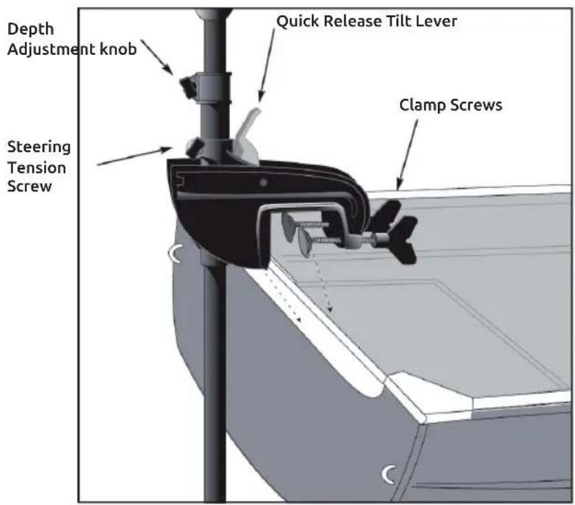
MOTOR INSTALLATION:
Install the motor on the transom of the boat. Be sure to tighten the clamp screws securely.
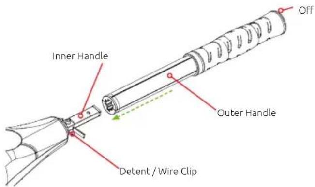
HANDLE INSTALLATION:
Remove the wire clip from the ball detent located on the inner handle. Install outer handle over inner handle. Position the handles so the detent ball and OFF are aligned. Push the outer handle into the control box until handle " clicks" into place. The handle is held in place with locking fingers, so some force may be required to lock the handles together.
CAUTION:
- Never operate your motor when it is out of the water.
Over-tightening the clamp screws can damage the bracket.
Once the handle is locked into the control box, it can be rotated and extended for normal use. Once the handle is installed, the assembly is permanent. Do not attempt to remove the handle.
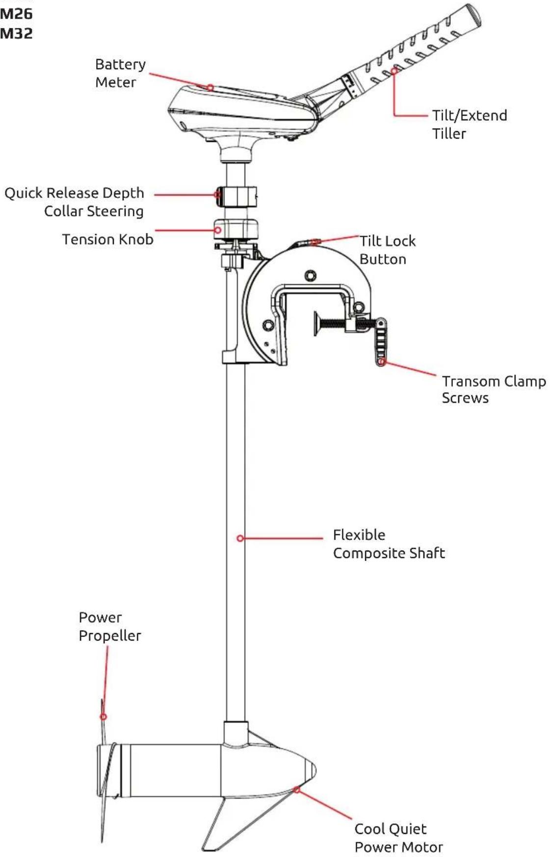
TILT ADJUSTMENT:
You can lock your motor in a vertical position, angle it for shallow water or tilt it completely out of the water.
- Firmly grasp the control head or composite shaft.
Depress and hold the tilt lock button. - Tilt to any of the ten positions on the mounting bracket.
- Release the button.
DEPTH ADJUSTMENT:
- Firmly grasp the composite shaft and hold it steady.
- Loosen the steering tension knob and depth collar knob until the tube slides freely.
- Raise or lower the motor to the desired depth.
- Tighten depth collar knob to secure the motor in place.
- Make sure the top of the motor is submerged at least 12^ to avoid churning or agitation of surface water.
STEERING ADJUSTMENT:
Adjust the steering tension knob to provide enough tension to allow the motor to turn freely, yet remain in position without being held or; Tighten the knob and lock the motor in a preset position to leave your hands free for fishing.
REVERSE THE CONTROL HEAD
If you wish to change the direction of propulsion, simply:
- Remove the collar screw and hex nut.
- Rotate the control head 180^ and align the screw holes.
- Replace the screw and hex nut to secure.
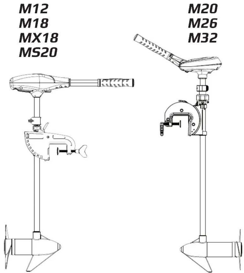
M12
M18
MX18
M520
M20 M26 M32
SPECIFICATIONS / INSTALLATION / ADJUSTMENTS
Specifications subject to change without notice.
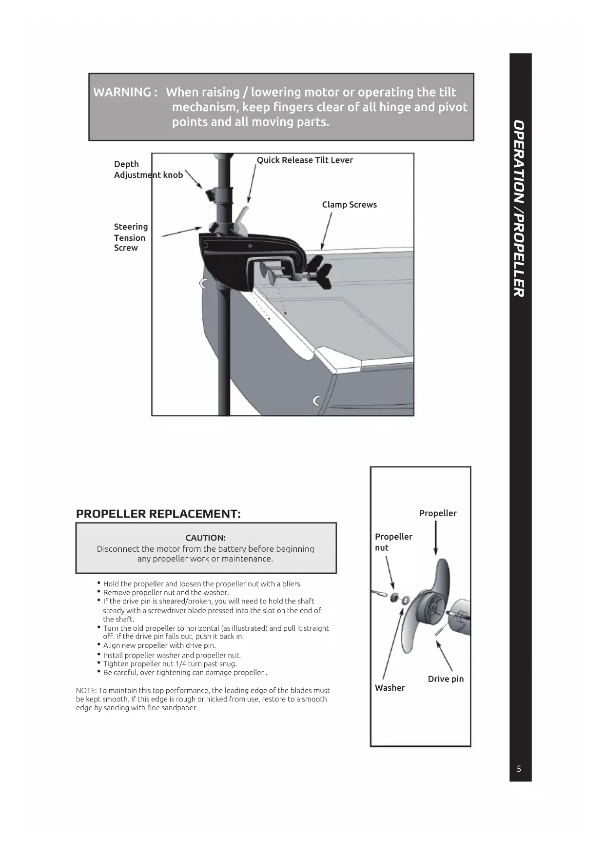
WARNING: When raising / lowering motor or operating the tilt mechanism, keep fingers clear of all hinge and pivot points and all moving parts.
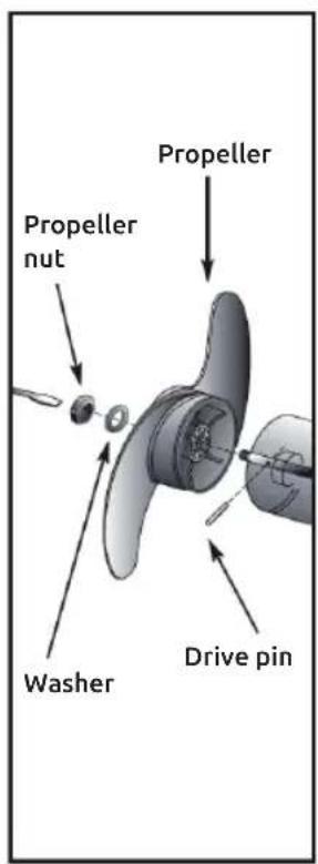
PROPELLER REPLACEMENT:
CAUTION:
Disconnect the motor from the battery before beginning any propeller work or maintenance.
- Hold the propeller and loosen the propeller nut with a pliers.
- Remove propeller nut and the washer.
If the drive pin is sheared/broken, you will need to hold the shaft steady with a screwdriver blade pressed into the slot on the end of the shaft. - Turn the old propeller to horizontal (as illustrated) and pull it straight off. If the drive pin falls out, push it back in.
- Align new propeller with drive pin.
Install propeller washer and propeller nut. - Tighten propeller nut 1/4 turn past snug.
- Be careful, over tightening can damage propeller.
NOTE: To maintain this top performance, the leading edge of the blades must be kept smooth. If this edge is rough or nicked from use, restore to a smooth edge by sanding with fine sandpaper.
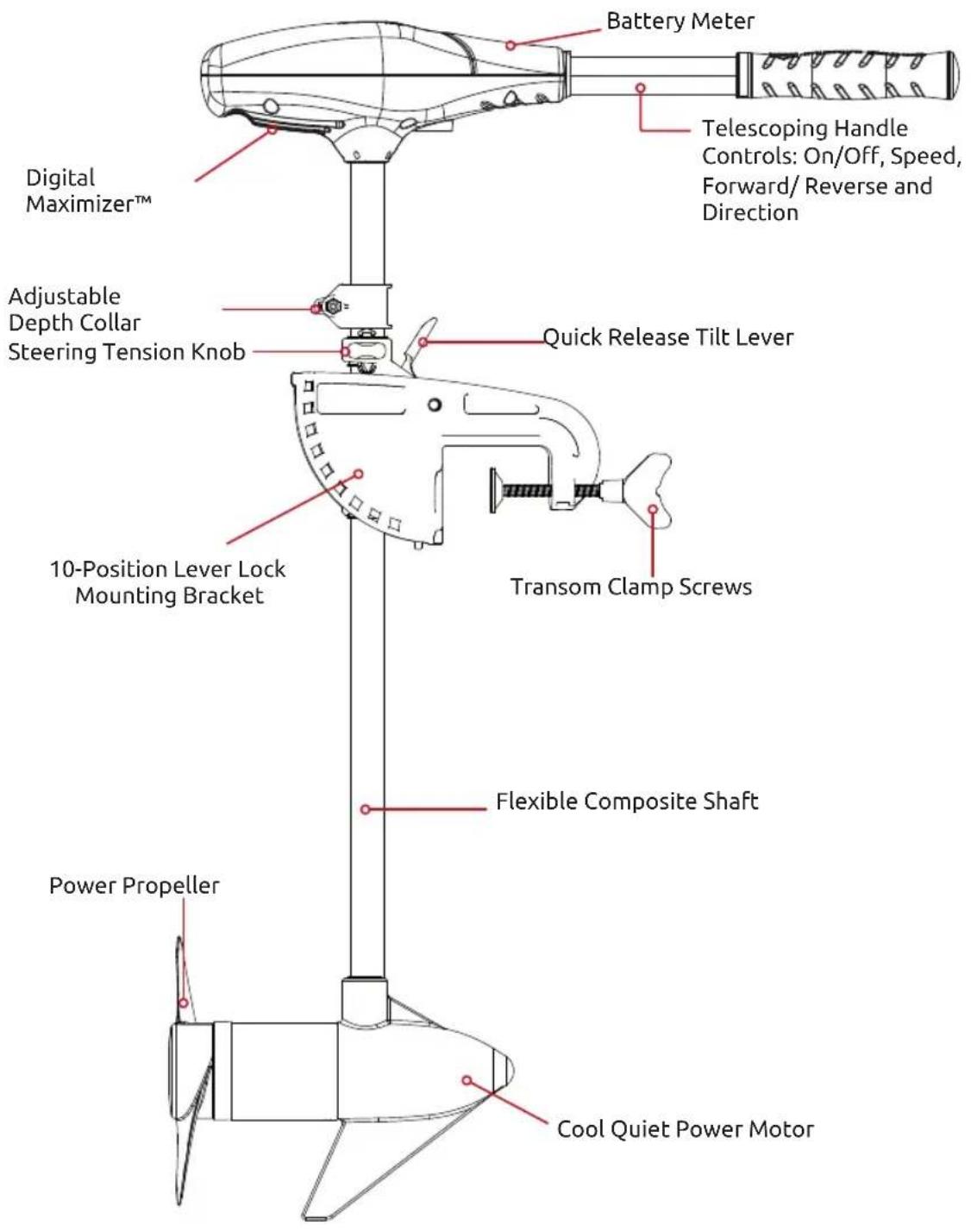
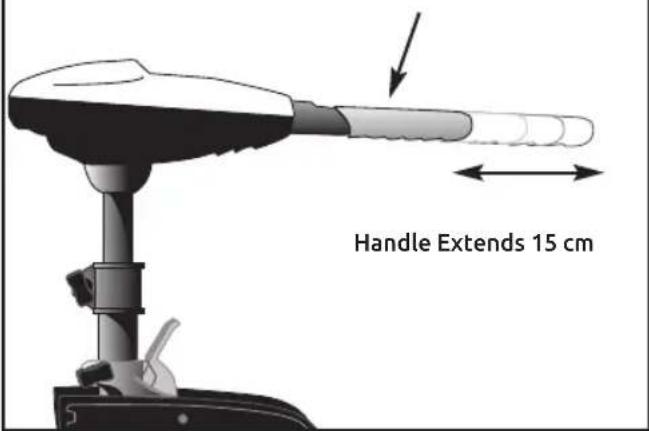
Telescoping TWIST TILLER
The 15 cm telescoping handle provides an additional extension for convenient operation various boats.
The twist feature of the tiller handle operates the speed control.
- Turn the handle counterclockwise from Off to any of the three reverse speeds and clockwise from Off to any of the five forward speeds.
Thrust decreases as you approach Off from either direction.
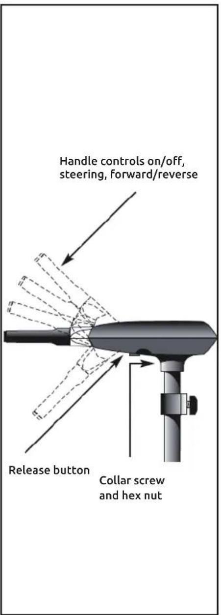
Handle controls on/off, steering, forward/reverse.
Tilt Twist Tiller:
This E-drive offers a choice of infinitely variable speeds as provided by the built-in Maximizer pulse width modulation system. The speed control may be operated in either direction, forward or reverse. Turn the tilt twist tiller handle counterclockwise from Off to increase reverse speed and clockwise from Off to increase forward speed. Thrust decreases as you approach Off from either direction. The numbers printed on the twist grip handle represent a percentage of maximum thrust. The handle has seven (7) available positions: 45^ down, horizontal, 15^ , 30^ and 45^ tilted up. The handle locks in the horizontal position, but can be tilted down by pushing the release button located on the left underside of the handle pivot.
CAUTION
never operate your motor when it is out of the water.
BATTERY INFORMATION:
The motors will operate with any deep cycle marine 12 volt battery. For best results, use a deep cycle marine battery with at least a 105 ampere hour rating. The actual ampere draw is subject to your particular environmental conditions and operation requirements. Failure to recharge lead-acid batteries (within 12-24 hours) is the leading cause of premature battery failure. For best results, use a variable rate charger to avoid overcharging. If you are using a crank battery to start a gasoline outboard, we recommend that you use a separate deep cycle marine battery for your E-Drive.
12 Volt Systems: 1. Make sure the motor is switched off (speed selector on "0ff").
- Connect the positive (+) red lead to the positive (+ battery terminal.
- Connect the negative (-) black lead to the negative (-) battery terminal.
- For safety reasons do not switch the motor on until the propeller is in the water.
NOTE: If installing a leadwire plug, observe proper polarity and follow the instructions in your boat owner's manual.
Advice regarding batteries: Never connect the (+) and the (-) terminals of the battery together.
Take care that no metal object can fall onto the battery and short the terminals. This would immediately lead to a short and utmost fire danger.
Recommendation: Use battery boxes and covered battery terminal clamps.
This motor is equipped with a "push to test" battery gauge. The LED provides an accurate display of the remaining charge in the battery. It is only accurate when the motor is off. The gauge reads as:
- Four lights indicate full charge.
- Three lights indicate good charge.
- Two lights indicate low charge.
One light indicates recharge.
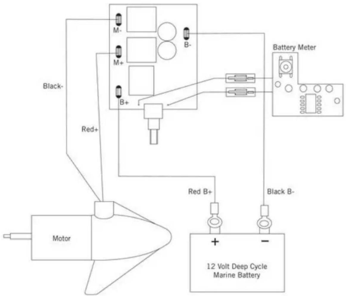
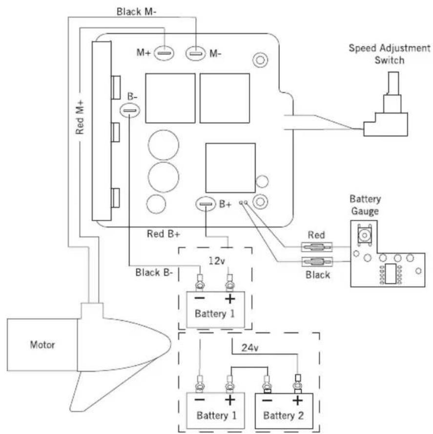
WIRING INSTALLATION:
An over-current protection device (circuit breaker or fuse) is strongly recommended. If you want to extend the battery cable longer than that provided with your unit, we recommend that you contact a Yamaha authorized dealer.
We recommend installing the breaker as close as possible to the battery / batteries.
NOTE: Wire Extension Length refers to the distance from the batteries to the trolling motor leads. Wire gauge is depending of extension length and power draw of the motor.
WARNING:
- For safety reasons, disconnect the motor from the battery or batteries when the motor is not in use or while the battery/batteries are being charged.
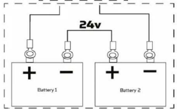
- Improper wiring of 24/36 volt systems could cause battery explosion.
- Local authorities can require that each ungrounded current-carrying conductor must be protected by a manually reset, trip-free circuit breaker or fuse. The type (voltage and current rating) of the fuse or circuit breaker must be sized accordingly to the trolling motor used.
MAXIMIZER:
The built-In Maximizer's solid state electronics create pulse width modulation to provide longer running time and extended battery life. With the Maximizer speed control, you may, in single battery applications, experience some interference in your depth finder display. We recommend that you use a separate deep cycle marine battery for your trolling motor to alleviate this condition.
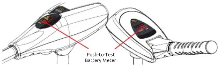
PUSH-TO-TEST BATTERY METER:
This motor is equipped with a "push-to-test" battery meter. The LED light provides an accurate display of the remaining charge in the battery. It is only accurate when the motor is off.
The meter reads as:
- One light indicates recharge.
- Two lights indicate low charge.
- Three lights indicate good charge.
Four lights indicate full charge.
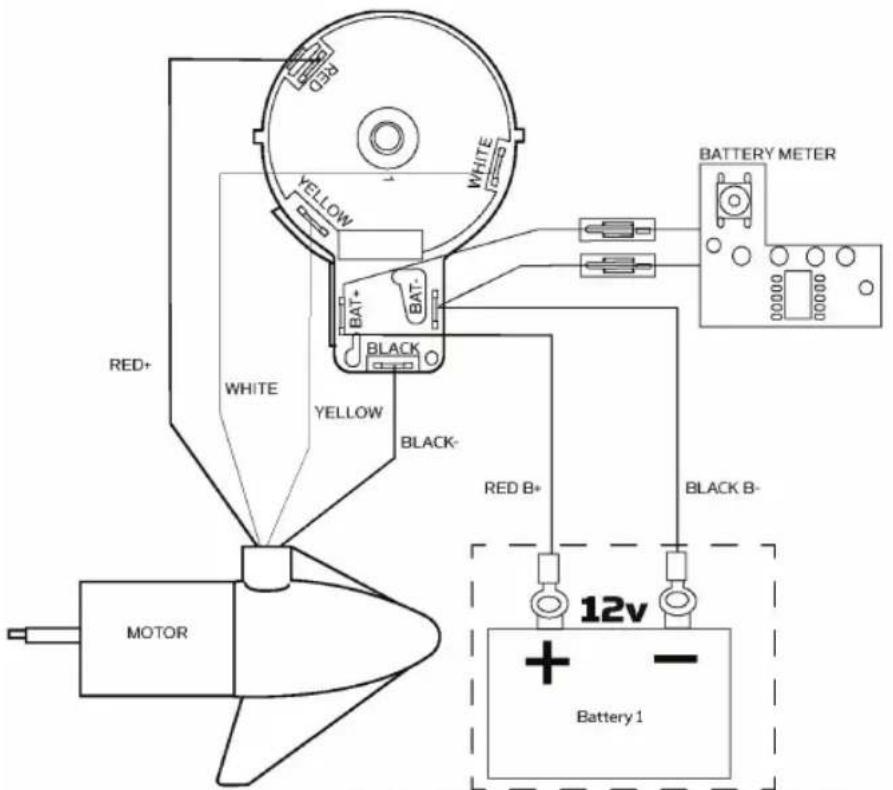
WARNING:
- Before connecting battery, make sure the twist tiller handle is in the OFF position.
- Use a 4mm thick gauge wire to extend power lead.
- Keep leadwire connection tight and solid to battery terminals.
- Locate battery in a ventilated compartment.
MX18
WARNING:
- Before connecting battery, make sure the twist tiller handle is in the OFF position.
- Use a 4mm thick gauge wire to extend power lead.
- Keep leadwire connection tight and solid to battery terminals.
- Locate battery in a ventilated compartment.
M12
M18
M520
M20 M26 M32
TROUBLESHOOTING:
- Motor fails to run or lacks power: Check battery connections for proper polarity. Make sure terminals are clean and corrosion free. If connections are good and battery has full charge, obtain service as instructed in warranty.
- Motor looses power after a short running time: Check battery charge, if low, restore to full charge.
- Motor is hard to steer: Loosen the steering tension knob. Lubricate the composite tube with an aqueous based silicon spray.
- You experience propeller vibration during normal operation: Remove and rotate the propeller 180^ . See removal instructions in propeller section.
NOTE: In case of any problem we recommend to contact an authorised Yamaha dealer.
MAINTENANCE:
- After use, these units should be rinsed with fresh water, then wiped down with a cloth dampened with an aqueous based silicon spray. Lightly coat all metal parts for prolonged storage.
- This motor is not designed for saltwater use. Use of this product in saltwater will void your warranty (except MS20 model).
- The propeller must be cleaned of weeds and fishing line. The line can get behind the propeller, wear away the seals and allow water to enter the motor. Check this after every 20 hours of operation.
- Before each use, check to see that the propeller nut is secure.
- To prevent accidental damage during trailering or storage, always disconnect the trolling motor from battery. For prolonged storage, lightly coat all metal parts with silicone spray.
- For maximum performance, restore battery to full charge before each use.
- Keep battery terminals clean with fine sandpaper or emery cloth.
LIMITED WARRANTY: Yamaha Motor warrants to the original purchaser that its E-drives are free from defects in materials or workmanship for a period of two (2) year from the date of purchase, except that this warranty shall not apply to any motors used commercially. The motor must be returned, prepaid and with proof of the date of purchase and serial number to any authorized Yamaha dealer.
NOTE: After inspection, we find that the product was defective in material or workmanship, we shall, at our option, repair or replace it without charge. We are not responsible for normal wear and tear or for defects caused by accidents, abuse, alteration, modification, misuse or improper care.
There are no other express warranties beyond the terms of this limited warranty. In no event shall any implied warranties, including merchantability and fitness for a particular purpose, extend beyond the duration of the express warranty contained herein. In no event shall Yamaha Motor, be liable for incidental or consequential damages.
MONTAGE VAN HANDGREEP:
INSTALACJA OKABLOWANIA:

Scan this QR code to get online your digital version or visit us at www.yamaha-motor.eu/gb/en/services/owner-manual/