 — Outboard motor — Mode d'emploi PDF")
Heml Master (2017) - Outboard motor YAMAHA - Free user manual and instructions
Find the device manual for free Heml Master (2017) YAMAHA in PDF.

| Product Type | Fully Integrated Boat Control System (Quad Engine with 6Y9 Display) |
| Brand | Yamaha |
| Model | Helm Master (2017) |
| Compatible Engines | Up to 4 outboard motors (PORT, CENTER PORT, CENTER STBD, STBD) |
| Display | Digital Network Gauge (6Y9) – twin gauge for port and starboard sides |
| Control Interface | Joystick lever, remote control levers (twin), EKS fob, push buttons |
| Power Supply | 12V DC from boat battery |
| Steering System | Hydraulic with steering pump, bypass valve, and cylinder |
| Key Functions | Joystick maneuvering, Set-Point (Stay Point, Fish Point, Drift Point), Trim Assist, Speed Control, Single Lever Mode, Center Engine Mode, Station Selector (dual station), Free Throttle, Engine Shut-Off |
| GPS Antenna | Included; required for Set-Point functions |
| Hydraulic Fluid | SeaStar EPS fluid or Chevron MD-3 automatic transmission fluid |
| Maintenance Intervals | Check hydraulic fluid level every 20 hours; inspect hoses every 100 hours; dealer service every 200 hours |
| Greasing Points | Steering cylinder shaft, support rod, tilt tube – apply marine grease |
| Safety Features | Engine shut-off switch with lanyard, alert notifications (red/yellow), steering bypass for emergency, warning labels |
| Spare Parts | Steering lock clips (part #6ES-23326-00), EKS fobs, hydraulic fluid |
| Environmental Protection | Keep manual in waterproof bag; avoid magnetic fields near EKS fob |
| Weight (estimated) | Approximately 15–20 kg (control system components only) |
| Dimensions (control box) | Approx. 300 x 200 x 150 mm (remote control box) |
Frequently Asked Questions - Heml Master (2017) YAMAHA
User questions about Heml Master (2017) YAMAHA
0 question about this device. Answer the ones you know or ask your own.
Ask a new question about this device
Download the instructions for your Outboard motor in PDF format for free! Find your manual Heml Master (2017) - YAMAHA and take your electronic device back in hand. On this page are published all the documents necessary for the use of your device. Heml Master (2017) by YAMAHA.
USER MANUAL Heml Master (2017) YAMAHA
FULLY INTEGRATED BOAT CONTROL SYSTEM (QUAD ENGINE WITH 6Y9 DISPLAY)
OPERATION MANUAL
natural_image
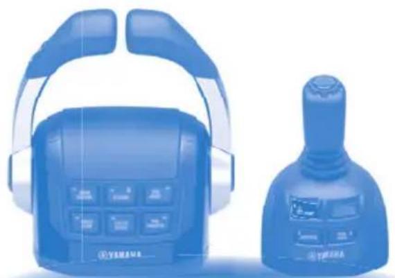
Blue medical device with headbuds and control panel, no visible text or symbolsRead this manual carefully before operating this system. Keep this manual onboard in a waterproof bag when boating.
To the operator
Thank you for selecting the Yamaha Helm Master control system. This operation manual contains information needed for proper operation, maintenance and care. A thorough understanding of these simple instructions will help you obtain maximum enjoyment from your new Yamaha.
The maneuvering performance of some boats, when operating in joystick mode, may be adversely affected by high winds and currents.
Yamaha continually seeks advancements and makes changes in product design and quality without notice. Therefore, while this manual contains the most current product information available at the time of printing, there may be minor discrepancies between the actual system and this manual. If you have any question about the operation or maintenance of your Helm Master control system, please consult a Yamaha dealer.
In this operation manual particularly important information is distinguished in the following ways.
This is the safety alert symbol. It is used to alert you to potential personal injury hazards. Obey all safety messages that follow this symbol to avoid possible injury or death.
WARNING
A WARNING indicates a hazardous situation which, if not avoided, could result in death or serious injury.
NOTICE
A NOTICE indicates special precautions that must be taken to avoid damage to the products or other property.
TIP:
A TIP provides key information to make procedures easier or clearer.
HELM MASTER
(QUAD ENGINE WITH 6Y9 DISPLAY)
OPERATION MANUAL
©2017 by Yamaha Motor Co., Ltd.
1st Edition, June 2017
All rights reserved.
Any reprinting or unauthorized use
without the written permission of
Yamaha Motor Co., Ltd.
is expressly prohibited.
Printed in Japan
P/N LIT-18626-11-84
6ES-2819V-10
Alert message information .... 1
Alert Notifications 1
Other Notifications 4
General information 5
List of abbreviations 5
Read labels and related manuals .... 5
Warning and caution labels ...... 6
Function and operation of components 11
EKS 12
EKS fob 12
Ignition switch 13
Start/stop switch 13
All ignition switch 13
All start/stop switch 13
Engine shut-off switch 13
Remote control box 14
Remote control lever 15
Lever friction adjuster 17
Free throttle switch 17
Single lever switch 17
Center engine switch 18
Speed control switch 19
Station selector switch (for dual station) 19
Trim assist switch 20
Power Trim and Tilt (PTT) switch ..... 20
Remote control active indicator ..... 23
Remote control alert indicator 23
Joystick control 24
Joystick lever 24
Joystick switch 26
High mode switch 26
Set-Point switch 27
Set-Point function 28
GPS signal reception level 30
Mode selection 31
Setting the maximum engine speed for "High mode" of Fish Point .... 31
Digital Network Gauge (6Y9) ...... 32
Twin gauge 33
Steering friction 33
Rudder angle 34
Alert display 34
Trip 35
Brightness 35
Tone 35
Favorites 36
Depth Alarms 36
Units 36
Tank Set 36
Off Timer 36
System Info 37
Trim Assist All 38
Trim Assist C. 39
Joystick calibration 41
Current 42
Trouble Codes 42
Sleep Mode 43
Pre-operation checks 44
Temporary actions in emergency 46
Steering malfunction 46
One engine's steering does not operate (locked or free) 46
All engine's steering do not operate 47
Engine interference protection ..... 48
Periodic maintenance 51
Maintenance table 51
Recommended hydraulic fluid ..... 53
Transportation with boat (trailering) 54
Alert message information
This section contains Helm Master control system alert information that will be displayed on the Digital Network Gauge (6Y9). Refer to operation manual 6Y9-2819U-** for additional information about the Digital Network Gauge (6Y9).
The Digital Network Gauge (6Y9) will display a window and alert icons to notify the operator when abnormalities in the Helm Master control system occur. A window will also be displayed when specific alert conditions occur.
When events requiring multiple windows occur, the window with the highest priority (red alert) is displayed first. Press the "SET" button to display windows in order of priority.
There are 2 types of windows, “Alert Notifications,” and “Other Notifications,” each displayed with its own color.
Alert Notifications: Red
Other Notifications: Yellow
Alert Notifications
Observe the following instructions for responding to each specific alert.
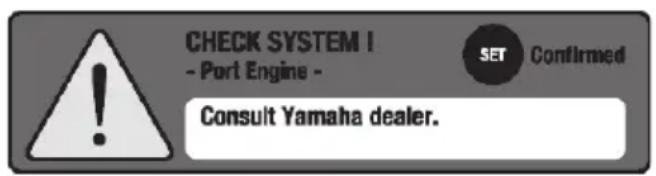

Helm Master control system trouble alert
Displayed if the Helm Master control system malfunctions.
Consult a Yamaha dealer.
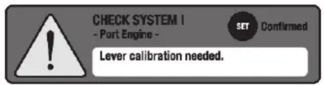

Lever sensor calibration alert
Displayed if the remote control lever sensor is un-calibrated or calibration has failed. Lever sensor calibration needed.
Consult a Yamaha dealer.
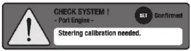

Steering sensor calibration alert
Displayed if the steering sensor is un-calibrated or calibration has failed. Steering sensor calibration needed.
Consult a Yamaha dealer.
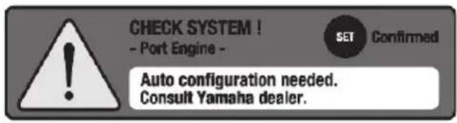

Auto configuration alert
Displayed the first time that the system is turned on after the Helm Master control system is installed, or if any Helm Master control system components are replaced. Consult a Yamaha dealer.
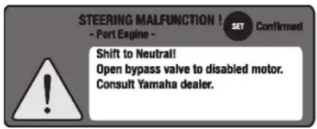

One engine steering malfunction alert
Displayed if an engine's steering system does not move properly. Consult a Yamaha dealer. See page 46 for further information.
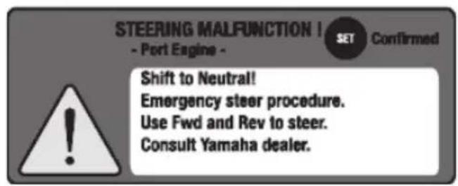

All engines' steering malfunction alert
Displayed if all engines' steering systems do not move properly. Consult a Yamaha dealer. See page 47 for further information.
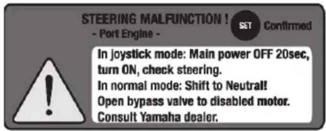

Engine interference protection alert
Displayed if the steering control system does not detect that an engine has reached the target steering angle. Consult a Yamaha dealer. See page 48 for further information.
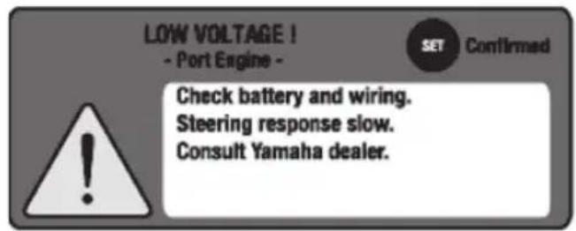

SCU low battery voltage alert
Displayed if a battery's voltage is too low. Consult a Yamaha dealer.
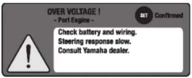

SCU high battery voltage alert
Displayed if an engine's battery voltage is too high.
Consult a Yamaha dealer.
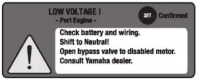

SCU low battery voltage alert (all engines)
Displayed if the voltages of all engines are too low. Steering response may be slow or stop working. Consult a Yamaha dealer.
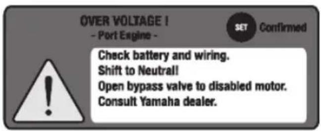

SCU high battery voltage alert (all engines)
Displayed if the voltages of all engines are too high. Steering response may be slow or stop working. Consult a Yamaha dealer.
Other Notifications
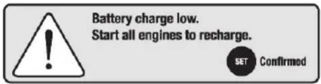
Battery low charge alert
Displayed if running a single engine for more than one hour. Start all engines to recharge the batteries.
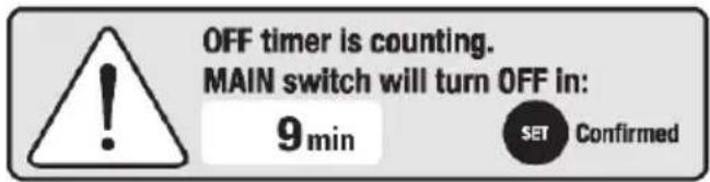
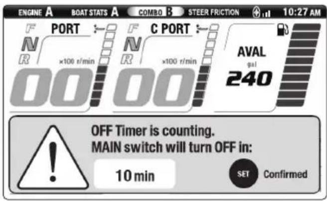
Off timer counting alert
Displayed 50 minutes after all engines have been stopped using start/stop switch, but the ignition switch is still ON. Turn the ignition switch OFF.
See page 36 for further information.
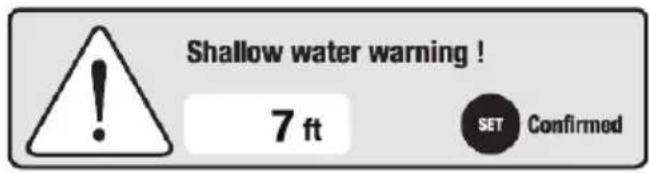
Shallow water alert
Displayed if the water depth is less than the set minimum depth (requires optional Multisensor).
General information
List of abbreviations
The following are abbreviations displayed on this meter or used in this manual.
| Abbreviation Description | |
| ABYC American Boat and Yacht Council | |
| DN Down side | |
| EKS Electronic Key Switch | |
| F | F o r w |
| ID Identification | |
| Mfg./Dlr. Manufacturer/Dealer | |
| N Neutral | |
| PORT Port side | |
| PTT Power Trim and Tilt | |
| R Reverse | |
| RPM Revolutions Per Minute | |
| STBD Starboard side | |
| SCU Steering Control Unit | |
| UP | Up side |
Read labels and related manuals
Before operating or working on this system:
- Read all labels carefully on the Helm Master control system components.
- Read this manual thoroughly and see other related manuals for outboard motors, Digital Network Gauge (6Y9) and boats for their basic operations.
If you need any additional information, contact your Yamaha dealer.
Warning and caution labels
The following labels are attached to the Helm Master control system components as shown below.
If these labels are damaged or missing, contact your Yamaha dealer for replacements.
TIP:
These components are installed on the boat in a location close to the stern. The installation position differs depending on the boat. For the proper installation position on your boat, contact a boat manufacturer or a Yamaha dealer.
SCU (Steering Control Unit)
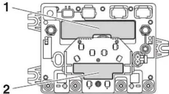
1
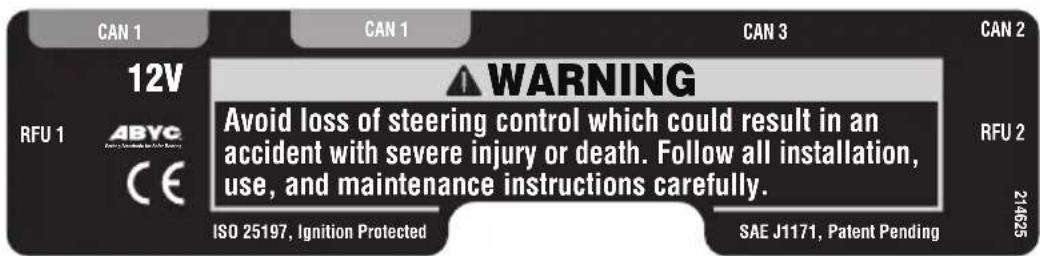
WARNING
Avoid loss of steering control which could result in an accident with severe injury or death. Follow all installation, use, and maintenance instructions carefully.
2
WARNING
Improper installation may cause loss of boat control. Follow Rigging Manual carefully. • Secure all connections.
- Cap all unused connectors. - Secure cables to tabs with cable ties.
682036
! WARNING
Improper installation may cause loss of boat control. Follow Rigging Manual carefully.
- Secure all connections.
- Cap all unused connectors.
- Secure cables to tabs with cable ties.
Steering pump and steering bypass valve
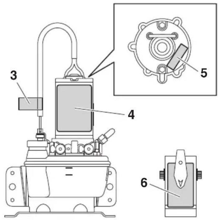
5
CAUTION HOT
CAUTION HOT
3
WARNING
HIGH POWER CABLE To avoid steering failure, do not extend or modify.
! WARNING
HIGH POWER CABLE To avoid steering failure, do not extend or modify.
6
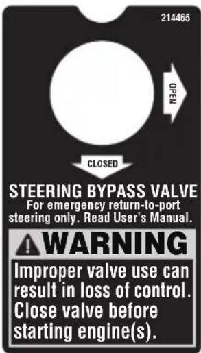
STEERING BY- PASS VALVE
For emergency return-to-port steering only. Read User's Manual.
WARNING
Improper valve use can result in loss of control.
Close valve before starting engine(s).
4
WARNING
Avoid loss of steering control which could result in an accident with severe injury or death.
- Check fluid level in pump reservoirs before each use (refer to User's Manual).
- Use only Teleflex SeaStar EPS fluid or Chevron MD-3 automatic transmission fluid. Use of any other fluid, including power steering, power trim and tilt, Dexron IV automatic transmission fluid, or brake fluid can cause permanent component damage.
• See Rigging Manual for maintenance requirements.

SAE J-1171

662041
WARNING
Avoid loss of steering control which could result in an accident with severe injury or death.
- Check fluid level in pump reservoirs before each use (refer to User's Manual).
- Use only Teleflex SeaStar EPS fluid or Chevron MD-3 automatic transmission fluid. Use of any other fluid, including power steering, power trim and tilt, Dexron IV automatic transmission fluid, or brake fluid can cause permanent component damage.
• See Rigging Manual for maintenance requirements.
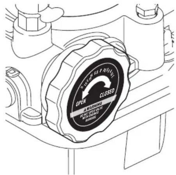
Steering pump with integrated bypass valve
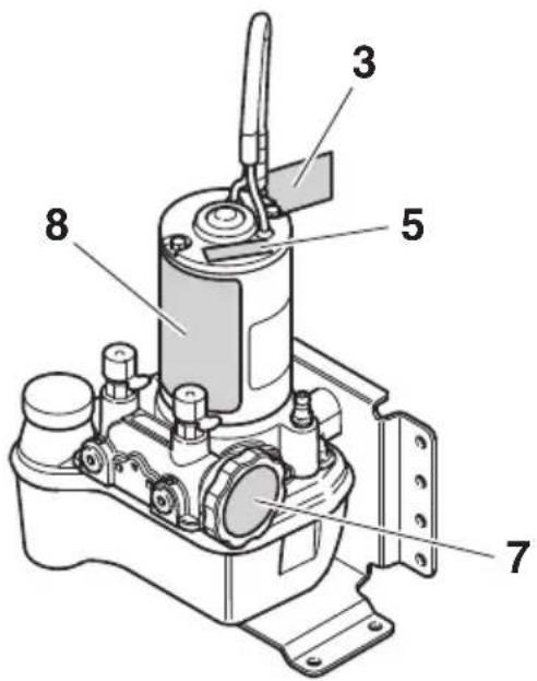
7
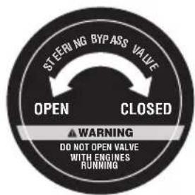
! WARNING
DO NOT OPEN VALVE WITH ENGINES RUNNING
8
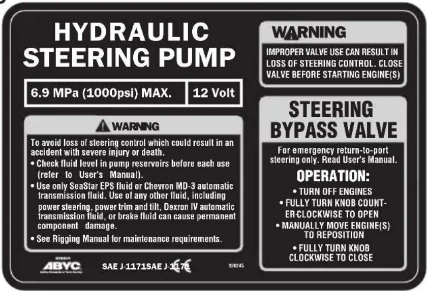
⚠ WARNING
IMPROPER VALVE USE CAN RESULT IN LOSS OF STEERING CONTROL. CLOSE VALVE BEFORE STARTING ENGINE(S)
STEERING
BYPASS
VALVE
For emergency return-to-port steering only. Read User's Manual. OPERATION:
• TURN OFF ENGINES
• FULLY TURN KNOB COUNTER-CLOCK-WISE TO OPEN
• MANUALLY MOVE ENGINE(S) TO REPOSITION
• FULLY TURN KNOB CLOCKWISE TO CLOSE
WARNING
To avoid loss of steering control which could result in an accident with severe injury or death.
- Check fluid level in pump reservoirs before each use (refer to User's Manual).
- Use only SeaStar EPS fluid or Chevron MD-3 automatic transmission fluid. Use of any other fluid, including power steering, power trim and tilt, Dexron IV automatic transmission fluid, or brake fluid can cause permanent component damage.
• See Rigging Manual for maintenance requirements.
Steering cylinder
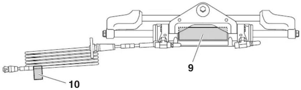
9
WARNING
Avoid loss of steering control:
- Read User's Manual before operating.
- Do not operate boat if any component is not in proper working condition.
- Keep magnets away from cylinder.
STEERING CYLINDER
Check steering components before each use:
- Check fluid level in pump reservoirs.
- Inspect all hoses, fittings, and cables for wear, kinking, and/or leaks.
- Check for binding, looseness, wear, and leaks, and anything obstructing steering.
- Verify immediate steering response when turning steering wheel(s).
682027
WARNING
Avoid loss of steering control:
- Read User's Manual before operating.
- Do not operate boat if any component is not in proper working condition.
- Keep magnets away from cylinder.
STEERING CYLINDER
Check steering components before each use:
- Check fluid level in pump reservoirs.
- Inspect all hoses, fittings, and cables for wear, kinking, and/or leaks.
- Check for binding, looseness, wear, and leaks, and anything obstructing steering.
- Verify immediate steering response when turning steering wheel(s).
10
WARNING
Avoid steering failure: Turn coupling clockwise to lock (click). Do not overtighten.
WARNING
Avoid steering failure: Turn coupling clockwise to lock (click). Do not overtighten.
Steering sensor extension harness
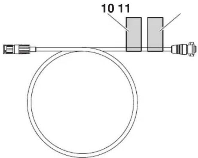
11
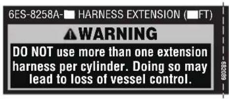
6ES-8258A-** HARNESS EXTENSION (**FT)
⚠ WARNING
DO NOT use more than one extension harness per cylinder. Doing so may lead to loss of vessel control.
**: Differs depending on the harness length.
Function and operation of components
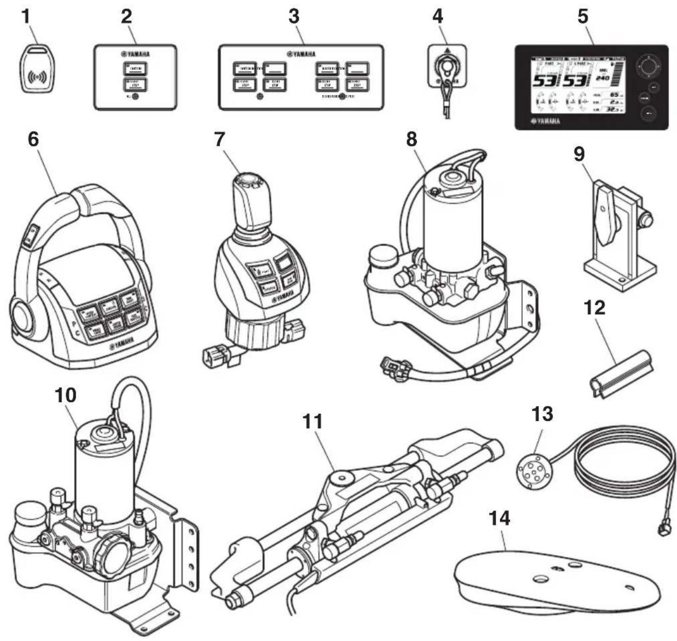
- EKS fob (2 pcs)
- EKS all panel
- EKS panel
- Engine shut-off switch panel
- Digital Network Gauge (6Y9) (2 pcs)
- Remote control box
- Joystick control
-
Steering pump (4 units)*
-
Steering bypass valve (4 units)*
- Steering pump with integrated bypass valve (4 units) ^*
- Steering cylinder (4 sets)
- Steering lock clip (2 pcs/cylinder)
- Notification light (2 pcs)
- GPS antenna
EKS
The EKS consists of the EKS All panel, EKS panel, and EKS fob. EKS functions: EKS locking/unlocking using EKS fob, ignition ON/OFF and engine starting and stopping.
The EKS All panel is equipped with an All ignition switch and an All start/stop switch. Pressing the All ignition switch will provide power for all engines. Pressing the All start/stop switch will start or stop all engines.
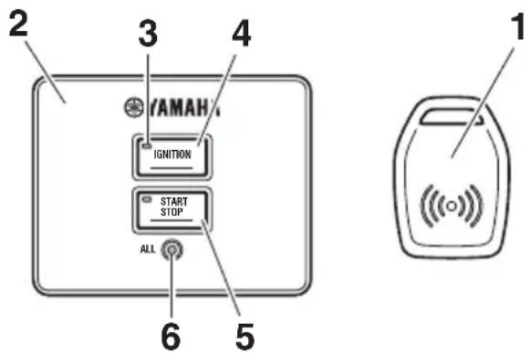
- EKS fob (2 pcs)
- EKS All panel
- Active indicator
- All ignition switch
- All start/stop switch
- Lock indicator
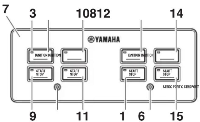
- EKS panel
- Ignition switch (PORT)
- Start/stop switch (PORT)
- Ignition switch (CENTER PORT)
-
Start/stop switch (CENTER PORT)
-
Ignition switch (CENTER STBD)
- Start/stop switch (CENTER STBD)
- Ignition switch (STBD)
- Start/stop switch (STBD)
■EKS fob
Place and hold the EKS fob over the lock indicator in EKS All panel or EKS panel to lock and unlock the EKS.
TIP:
- Be sure to lock the EKS when leaving the boat, or when leaving the operator's seat if children are nearby. Also, check that the lock indicator is blinking.
- Rapid repeat operation of the EKS fob lock/unlock function may result in improper operation of the EKS. When locking or unlocking the EKS, remove the EKS fob from over the lock indicator and wait at least 1-second before initiating another lock/unlock command.
- When locking/unlocking with the EKS fob, do not place the key close to devices possessing a magnetic field, as this may prevent the lock/unlock operation.
- The EKS will register up to four EKS fobs. Have a Yamaha dealer register any additional EKS fobs.
- When operating or stopping the boat, be sure to carry the EKS fob with you and take care not to lose it.
- If any EKS fob is lost, be sure to have a Yamaha dealer delete the registration of the lost key number for security reasons.
- While operating the ignition switch or engine start switch, do not turn the steering wheel or perform any system operations at the same time, otherwise unexpected errors may occur.
- Interference from other electronic devices (radios) could affect locking and unlocking of the system. Confirm the system has locked before leaving the boat. Repeat the locking/unlocking procedure if necessary.
Lock
When the EKS fob is placed over the lock indicator, the beeper sounds once. This indicates the lock mode is selected and the ignition switch cannot be turned to "ON". When in lock mode, the EKS panel lock indicators blink. When the ignition switch is OFF, or the ignition switch is ON and the engines are not running, locking can be performed.
Unlock
When the EKS fob is placed over the lock indicator, the beeper sounds twice. This indicates the unlock mode is selected and the ignition switch can be turned to "ON".
| EKS | Number of beeps | Engine can be started | Lock indicator |
| Lock 1 beep No Blink | |||
| Unlock 2 beeps Yes Off | |||
Ignition switch
Pushing the ignition switch turns the power to each engine ON and OFF. When the power is ON, the active indicator will be illuminated.
■Start/stop switch
Pushing the start/stop switch starts and stops each engine. The active indicator will be illuminated when the engine is running.
■All ignition switch
Pushing the All ignition switch turns power to all engines ON and OFF. The active indicators will be illuminated when the power is ON.
■All start/stop switch
Pushing the All start/stop switch starts and stops all engines. The active indicators will be illuminated when the engines are running.
Engine shut-off switch
The clip must be attached to the engine shut-off switch for the engines to run. The cord should be attached to a secure place on the operator's clothing, or arm or leg. Should the operator fall overboard or leave the helm, the cord will pull out the clip, turning all engines OFF. This will prevent the boat from running away under power.
WARNING
Attach the engine shut-off cord to a secure place on your clothing, or your arm or leg while operating. Do not attach the cord to clothing that could tear loose. Do not route the cord where it could become entangled, preventing it from functioning. Avoid accidentally pulling the cord during normal operation. Loss of engine power means the loss of most steering control. Also, without engine power, the boat could slow rapidly. This could cause people and objects in the boat to be thrown forward.
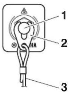
- Engine shut-off switch
- Clip
- Engine shut-off cord (lanyard)
Remote control box
The remote control box provides shift and throttle operation and the following control system functions.
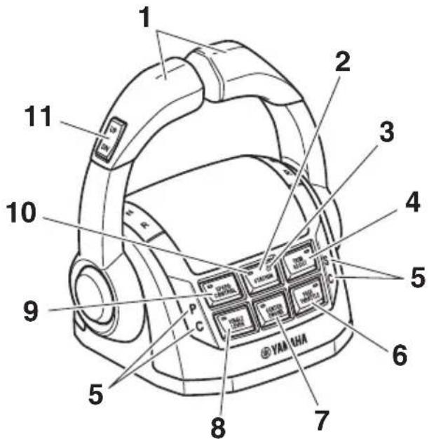
- Remote control lever
- Station selector switch
- Station lock indicator
- Trim assist switch
- Remote control alert indicator
- Free throttle switch
- Center engine switch
- Single lever switch
- Speed control switch
- Active indicator (station selector switch active indicator)
- PTT switch (All)
- PTT switch (STBD)
- PTT switch (Center) and Engine RPM switch
- PTT switch (PORT)
TIP:
The PTT (Center) control and the engine RPM control share the same switch depending on the mode selected. See page 19 for further information.
Function and operation of components
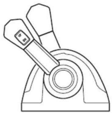
■Remote control lever
Moving the remote control levers from the neutral (N) position to the forward (F) position (towards the bow of the boat) makes the boat move forwards, while moving it to the reverse (R) position (towards the stern of the boat) makes the boat move backwards. The boat will be moving with the engine at idle. Moving the lever farther opens the throttle, and the engine will begin to accelerate.
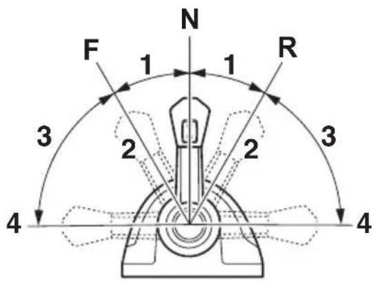
- Shift
- Fully closed
- Throttle
- Fully open
The twin lever provides control of gear shifting and throttle operation for all engines. The PORT and CENTER PORT engines are controlled by the PORT control lever. The STBD and CENTER STBD engines are controlled by the STBD control lever.
The CENTER PORT engine's operation is synchronized with the PORT engine operation.
The CENTER STBD engine's operation is synchronized with the STBD engine operation.
natural_image
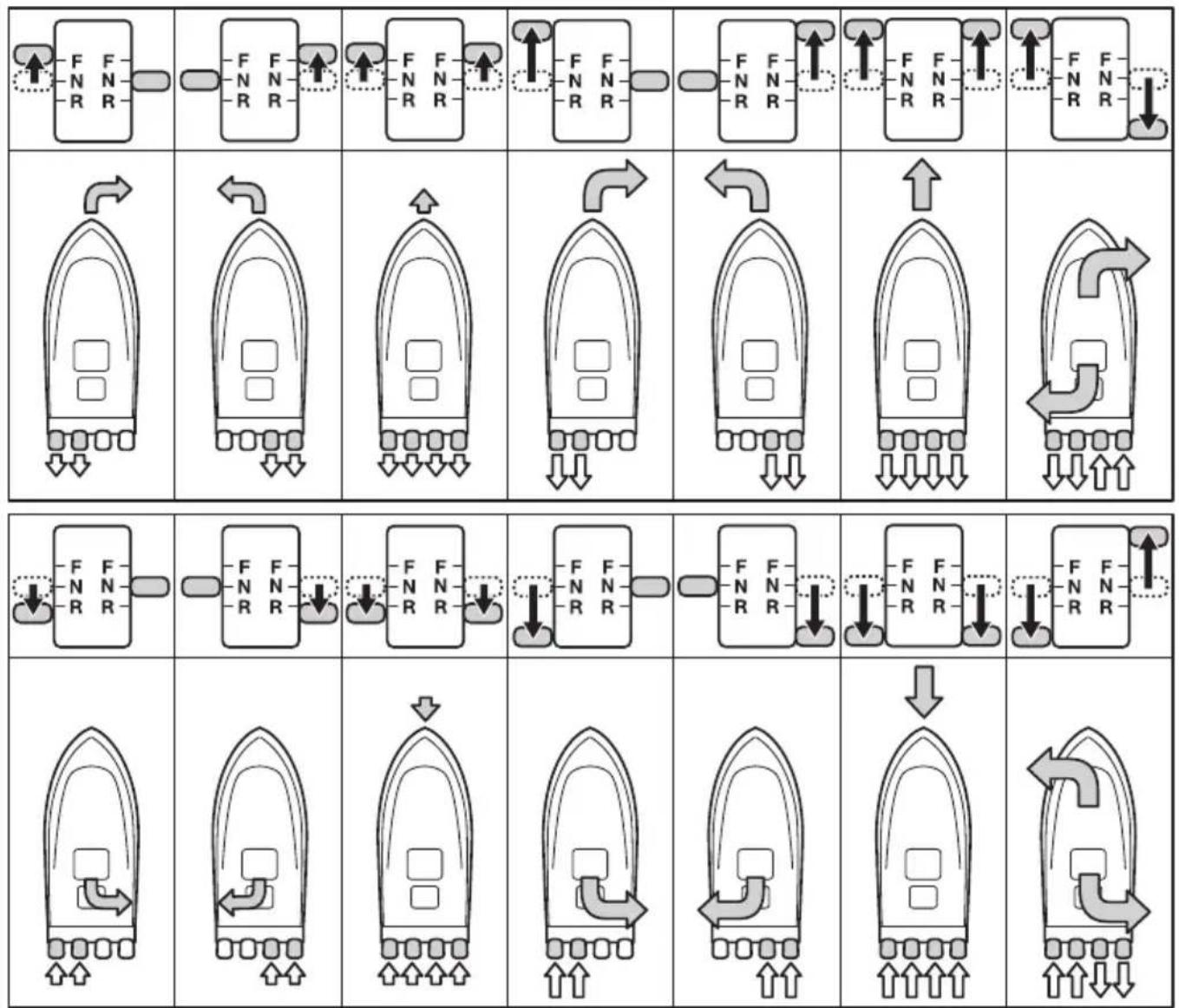
Technical line drawing of a mechanical lever assembly (no text or symbols)By moving both remote control levers, the boat can be maneuvered as shown below.
flowchart
graph TD
    A["Force Application"] --> B["Force Adjustment"]
    B --> C["Force Rotation"]
    C --> D["Force Pulling"]
    D --> E["Force Discharge"]
    E --> F["Force Discharge Return"]
    F --> G["Force Discharge Return"]
    G --> H["Force Discharge Return"]
    H --> I["Force Discharge Return"]
    I --> J["Force Discharge Return"]
    J --> K["Force Discharge Return"]
    K --> L["Force Discharge Return"]
    L --> M["Force Discharge Return"]
    M --> N["Force Discharge Return"]
    N --> O["Force Discharge Return"]
    O --> P["Force Discharge Return"]
    P --> Q["Force Discharge Return"]
    Q --> R["Force Discharge Return"]
    R --> S["Force Discharge Return"]
    S --> T["Force Discharge Return"]
    T --> U["Force Discharge Return"]
    U --> V["Force Discharge Return"]
    V --> W["Force Discharge Return"]
    W --> X["Force Discharge Return"]
    X --> Y["Force Discharge Return"]
    Y --> Z["Force Discharge Return"]
A. Lever operation
B. Boat direction and turning force (The size of the arrow is proportional to the turning force.)
C. Propulsion
■Lever friction adjuster
The remote control can be adjusted to suit operator preference. Friction brakes adjust the effort to move the remote control levers. Shift position detents adjust the click felt when engaging the shift positions. Turn the adjusters clockwise to increase the friction or detent pressure. Turn counterclockwise to reduce the friction or detent pressure.
WARNING
- If the friction brakes or shift position detents are too loose, the remote control levers may move too quickly, causing accidents.
- Do not over-tighten the friction brakes and shift position detents. If the remote control levers movement is too heavy, it may hinder the handling of the boat, causing accidents.
- Friction brakes
- Shift position detents
■Free throttle switch
When activated, the free throttle switch allows opening the throttles of all engines without engaging forward or reverse gear.
With the remote control levers in the N position, press the free throttle switch, and then move the remote control levers forward to open and close the throttle. Moving the remote control levers rearward will also open and close the throttle. The active indicator will be illuminated during operation.
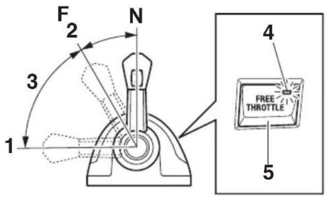
- Fully open
- Fully closed
- Free accelerator
- Active indicator
- Free throttle switch
The free throttle switch cannot be operated unless the remote control levers are in the N position. To leave free throttle mode, place the remote control levers in the N position and press the free throttle switch. The active indicator will go out.
■Single lever switch
The single lever switch allows shift and throttle operation of all engines using the PORT remote control lever. When activated, the STBD remote control lever will be inoperable.
Place the remote control levers in the N position and press the single lever switch to operate all engine throttles and gear shifts with the PORT remote control lever. The active indicator will be illuminated during operation.
Place both remote control levers in the neutral (N) position and press the center engine switch (the single lever mode must not be activated). The active indicator will be illuminated during operation.
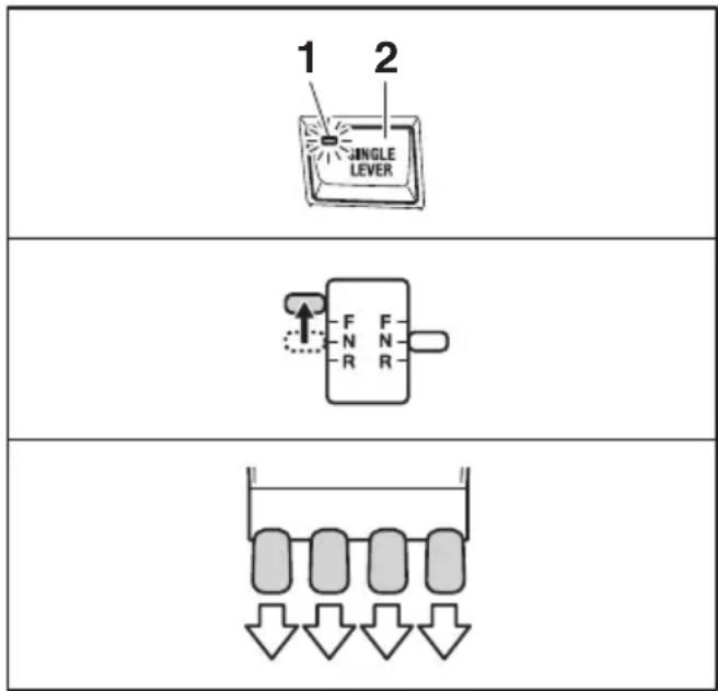
- Active indicator
- Single lever switch
The single lever switch can only be activated or deactivated when both remote control levers are in the neutral (N) position. To leave single lever mode, place the remote control levers in N position and press the single lever switch. The active indicator will go out.
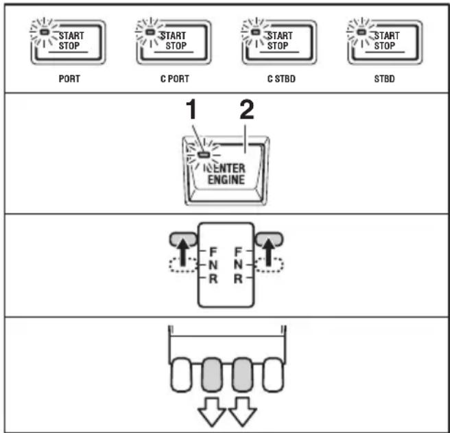
■Center engine switch
The center engine switch allows the operation of only center engines while all engines are running.
The CENTER PORT engine is controlled by PORT remote control lever and the CENTER STBD engine is controlled by STBD remote control lever.
flowchart
graph TD
    A["START STOP"] --> B["C PORT"]
    B --> C["C STBD"]
    C --> D["START STOP"]
    style A fill:#f9f,stroke:#333
    style B fill:#f9f,stroke:#333
    style C fill:#f9f,stroke:#333
    style D fill:#f9f,stroke:#333
    subgraph 1 2
        E["ENTER ENGINE"]
    end
    subgraph 2
        F["F N R"]
        G["F N R"]
        H["F N R"]
        I["F N R"]
        J["F N R"]
        K["F N R"]
        L["F N R"]
        M["F N R"]
        N["F N R"]
        O["F N R"]
        P["F N R"]
        Q["F N R"]
        R["F N R"]
        S["F N R"]
        T["F N R"]
        U["F N R"]
        V["F N R"]
        W["F N R"]
        X["F N R"]
        Y["F N R"]
        Z["F N R"]
        AA["F N R"]
        AB["F N R"]
        AC["F N R"]
        AD["F N R"]
        AE["F N R"]
        AF["F N R"]
        AG["F N R"]
        AH["F N R"]
        AI["F N R"]
        AJ["F N R"]
        AK["F N R"]
        AL["F N R"]
        AM["F N R"]
        AN["F N R"]
        AO["F N R"]
        AP["F N R"]
        AQ["F N R"]
        AR["F N R"]
        AS["F N R"]
        AT["F N R"]
        AU["F N R"]
        AV["F N R"]
        AW["F N R"]
        AX["F N R"]
        AY["F N R"]
        AZ["F N R"]
        BA["F N R"]
        BB["F N R"]
        BC["F N R"]
        BD["F N R"]
        BE["F N R"]
        BF["F N R"]
        BG["F N R"]
        BH["F N R"]
        BI["F N R"]
        BJ["F N R"]
        BK["F N R"]
        BL["F N R"]
        BM["F N R"]
        BN["F N R"]
        BO["F N R"]
        BP["F N R"]
        BQ["F N R"]
        BR["F N R"]
        BS["F N R"]
        BT["F N R"]
        BU["F N R"]
        BV["F N R"]
        BW["F N R"]
        BX["F N R"]
        BY["F N R"]
        BZ["F N R"]
        CA["F N R"]
        CB["F N R"]
        CC["F N R"]
        DD["F N R"]
        DEF["F N R"]
    end
- Active indicator
- CENTER engine switch
To leave the center engine mode, place both remote control levers in the neutral (N) position and press the center engine switch. Also, stopping one or more of the engines will deactivate the center engine mode. The active indicator will go out.
TIP:
When only center engine(s) is running by the START/STOP ignition switch(es), the CENTER PORT engine can be controlled by the PORT remote control lever and the CENTER STBD engine can be controlled by the STBD remote control lever without using the center engine switch.
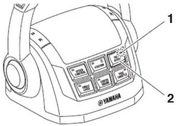
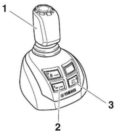
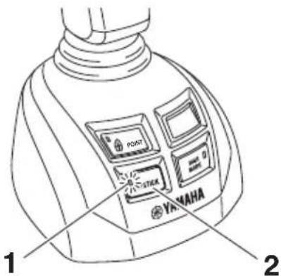
■Speed control switch
The speed control switch "1" in conjunction with the engine RPM (center trim) switch "3" allow the operator to easily make small engine speed adjustments.
The remote control lever(s) must be in forward (F) position before activating speed control. The active indicator will be illuminated during operation. Each time the UP side of the engine RPM switch is pressed the engine speed will gradually increase and pressing the DN side of the switch will gradually decrease speed.
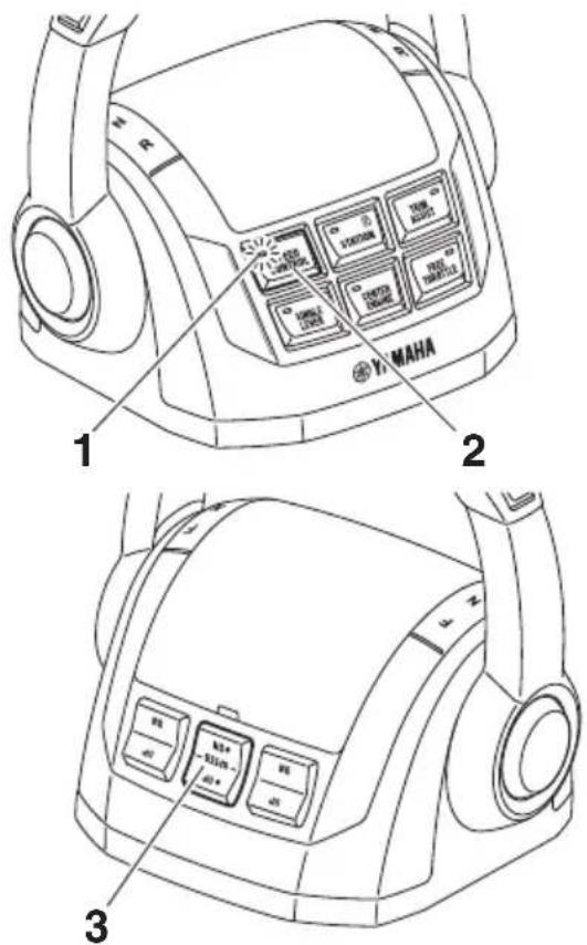
- Active indicator
- Speed control switch
- Engine RPM switch
Pressing the speed control switch will cancel the speed control mode.
TIP:
When in speed control mode, the PTT switches (STBD, Center, and PORT) do not provide PTT function.
■Station selector switch (for dual station)
The station selector switch allows selecting which station, main or second, will operate the engines. When selecting a station the remote control levers at both stations must be in neutral (N). The active indicator will illuminate at the selected station. When the operating station is changed, "Station activated" will displayed on the Digital Network Gauge (6Y9) at the selected station and a single beep will sound. Changing operating stations will deactivate any other functions, except trim assist, that were active at the other station.
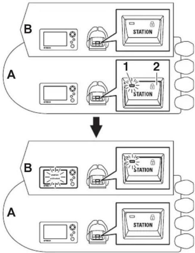
flowchart
graph TD
    A["Device A: Microwave oven, Dish, Station"] -->|1| B["Device B: Station extended, Dish, Station"]
    B -->|2| C["Device B: Station extended, Dish, Station"]
- Active indicator
- Station selector switch
A. Main station helm
B. 2nd station helm
Station lock (dual station only)
Pressing the station selector switch at the active station will prevent the transfer of station control from the other station.
During operation, the station lock indicator will be illuminated at both stations.
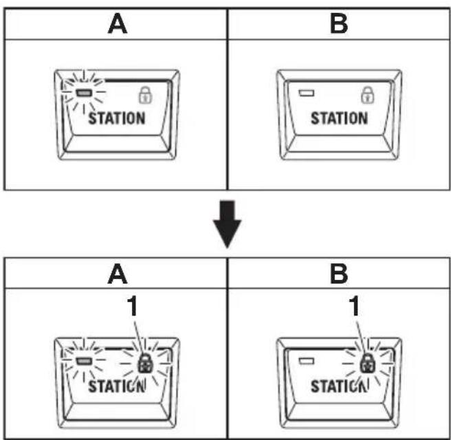
flowchart
graph TD
    A["Station Block A"] -->|↓| B["Station Block B"]
    A --> C["1 Station"]
    B --> D["1 Station"]
1. Station lock indicator
A. Main station helm
B. 2nd station helm
■Trim assist switch
The trim assist switch allows the trim angle of all engines to be automatically adjusted according to the engine speed.
The trim assist function can be activated when the remote control levers are in the forward (F) position. The active indicator will be illuminated during operation. See page 38 for
information on setting engine speeds and the appropriate trim angle settings.
TIP:
The trim assist settings must be made in order for the trim assist switch to function.
- Active indicator
- Trim assist switch
Trim assist mode does not operate in the free throttle mode and joystick mode. Pushing the trim assist switch exits from trim assist mode. The active indicator will go out.
When the trim assist function has been switched ON, it will remain active until cancelled by the operator even when turning the ignition switch OFF and back to ON.
■Power Trim and Tilt (PTT) switch
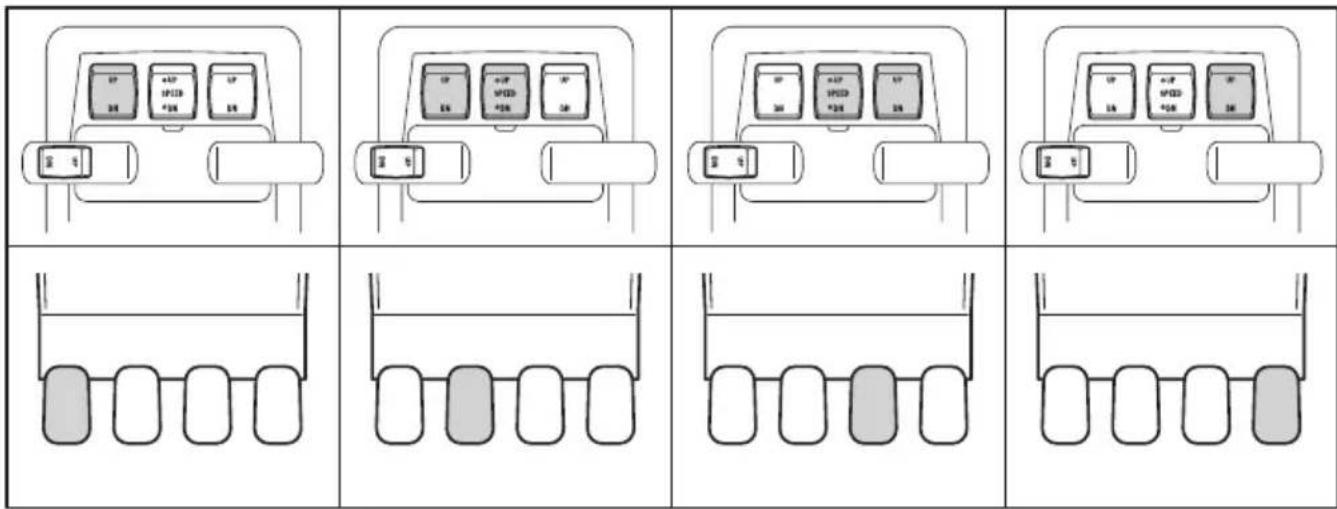
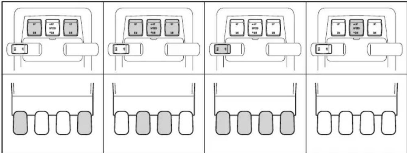
The PTT system adjusts the position of the engines in relation to the transom. PTT switch "1" controls all engines simultaneously. PTT switches "2", "3" and "4" control each engine individually. When the engines are in the fully down position, pressing UP will first move the engine(s) through the trim range then into tilt range. Pressing DN will lower the engine(s). When the switches are released, the engine(s) will stop in it's current position.
WARNING
- Be sure all people are clear of the outboard motor when adjusting the trim angle. Body parts can be crushed between the motor and the clamp bracket when the motor is trimmed or tilted.
- Use caution when trying a trim position for the first time. Increase speed gradually and watch for any signs of instability or control problems. Improper trim angle can cause loss of control.
NOTICE
The engines should not be operated when in the tilt range. If absolutely necessary due to shallow water conditions: make sure the cooling water inlets are submerged, do not run above idle speed and do not accelerate until the engines are lowered into the trim range.
TIP:
When speed control is active, the center PTT switch "3" acts as the engine RPM switch. Switches "2" and "4" will be inactive. Raise and lower all engines using PTT switch "1".
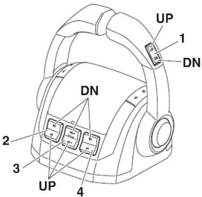
- PTT switch (All)
- PTT switch (STBD)
- PTT switch (Center)
- PTT switch (PORT)
Shaded icons show the PTT switches which are simultaneously operated and the corresponding outboard motors.
■Remote control active indicator
When the ignition switches are turned ON, the active indicator on the station selector will illuminate indicating the station either: the remote control is operational (single station) or the selected station is operational (dual stations).
When the active indicator is:
- Illuminated: Operation of the shift and throttle is possible.
- Off: Shift and throttle not operational.
- Remote control active indicator (Station selector switch active indicator)
■Remote control alert indicator
If a steering control system malfunction occurs, remote control alert indicators will blink. The blinking alert indicators show which engine's steering system has a malfunction. A buzzer will also sound (alternating ON/OFF) to alert the operator. Pushing the "SET" button on the Digital Network Gauge (6Y9) will stop the buzzer.
TIP:
Depending on the type of engine malfunction, pressing the "SET" button of the Digital Network Gauge (6Y9) may not stop the buzzer.
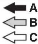
| A | 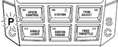 |
| B | 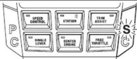 |
| C | 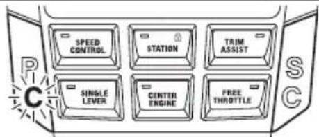 |
| D |  |
1. Remote control alert indicator
A. PORT engine malfunctions
B. STBD engine malfunctions
C. CENTER PORT engine malfunctions
D. CENTER STBD engine malfunctions
Joystick control
Low speed shifting, throttle operation and steering of all engines can be performed with the joystick lever when activated.
- Joystick lever
- Joystick switch
- High mode switch
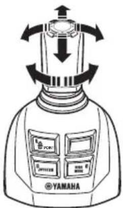
■Joystick lever
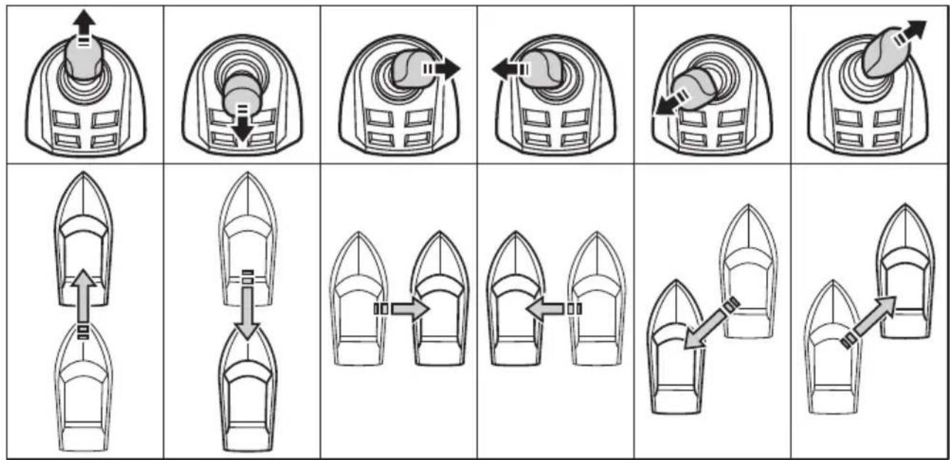
Moving the joystick lever left, right, forwards, backwards, or diagonally moves the boat in the corresponding direction.
The joystick will return to the neutral (N) position when released.
Maneuvering with the joystick lever
flowchart
graph TD
    A["Top Boat"] --> B["Downward Arrow"]
    B --> C["Upward Arrow"]
    C --> D["Leftward Arrow"]
    D --> E["Rightward Arrow"]
    E --> F["Bottom Right Arrow"]
    G["Bottom Boat"] --> H["Downward Arrow"]
    H --> I["Upward Arrow"]
    I --> J["Leftward Arrow"]
    J --> K["Rightward Arrow"]
    K --> L["Bottom Left Arrow"]
    M["Bottom Boat"] --> N["Downward Arrow"]
    N --> O["Upward Arrow"]
flowchart
graph TD
    A["Motor with clockwise arrow"] --> B["Gear with clockwise arrow"]
    B --> C["Valve with clockwise arrow"]
    C --> D["Arrow to valve with clockwise arrow"]
    D --> E["Arrow to valve with clockwise arrow"]


A. Lever operation
B. Boat direction
TIP:
Wind, current, load placement in the boat and hull design may cause the direction of the boat's movement to be different than the position of the joystick. Rotate the knob on the joystick as necessary to correct the direction of movement.
Joystick switch
The joystick switch transfers boat operation from the remote control and steering helm to the joystick.
While the engine is running, placing the remote control lever and the joystick lever in the N position and pushing the joystick switch enters the joystick mode, allowing operation with the joystick lever.
The active indicator illuminates during operation. While in the joystick mode, the engine speed is limited and the steering wheel is locked.
- Active indicator
- Joystick switch
Pressing the joystick switch, shifting the remote control lever into F or R, or stopping the PORT or STBD engine exits the joystick mode. Even if the center engine is stopped, the PORT and STBD engines can be controlled by the joystick. The active indicator will turn OFF.
TIP:
When exiting the joystick mode even if the steering wheel is turned, the engines will automatically return to the initial positions.
■High mode switch
The function of this switch is to allow the engine to run at a higher speed than normal, if extra power is needed (e.g., when there is strong wind or current). Pressing the high mode switch while in joystick mode engages the high mode. The active indicator illuminates during operation.
- Active indicator
- High mode switch
Pressing the high mode switch again exits high mode. The active indicator will turn OFF.
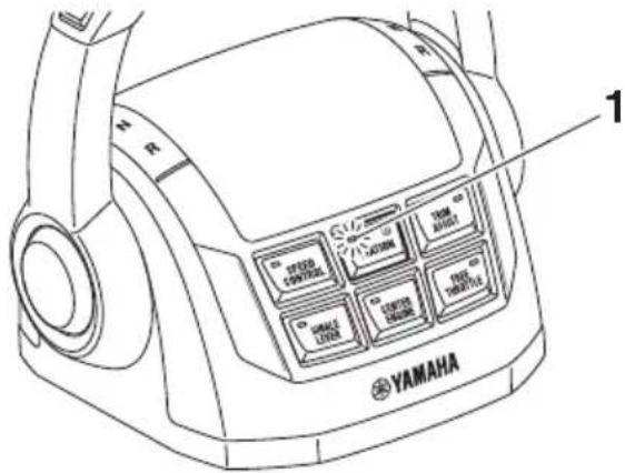
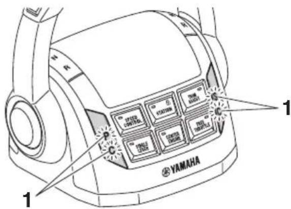
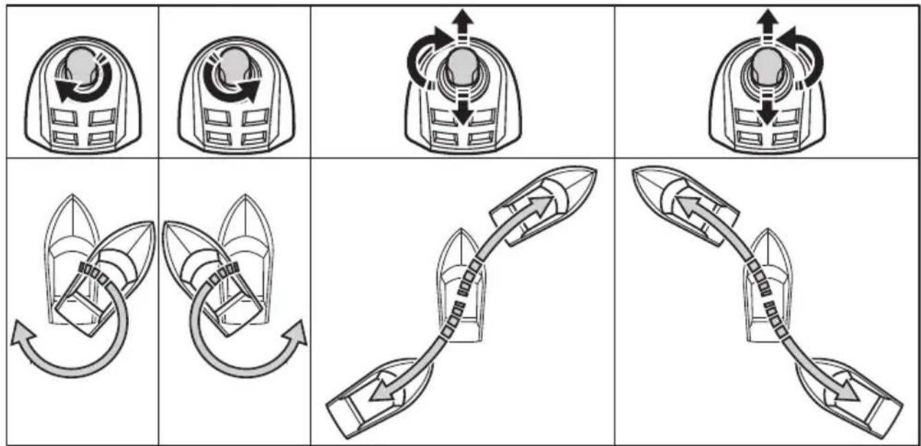
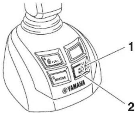
■Set-Point switch
The Set-Point switch activates the selected Set-Point mode.
This switch can activate 4 Set-Point modes. However, only 2 of them can be preset for your preference. Pressing the switch briefly or long can select the preset mode.
Two notification lights, located at each side of the transom, will blink while the Set-Point function is active.
The two blinking notification lights indicate the Set-Point function is active and people should stay out of the water.
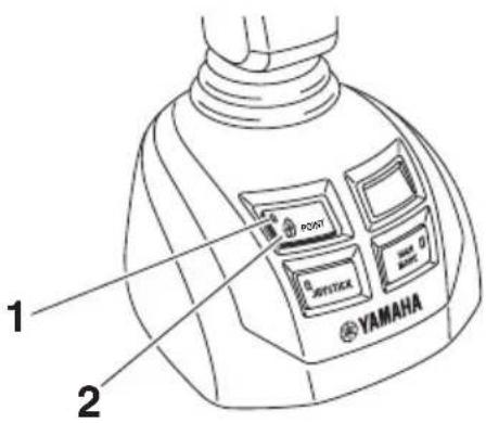
- Active indicator
- Set-Point switch
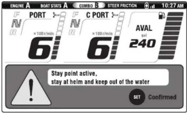
While the Set-Point function is active, the selected mode is displayed as follows.
TIP:
- If the GPS antenna cannot receive GPS signals, the Set-Point function will be cancelled. The Set-Point function will also be cancelled when the remote control lever, free throttle switch, or center engine switch is operated.
- The brightness of the notification light is automatically adjusted based on the brightness of the surroundings.
Set-Point function
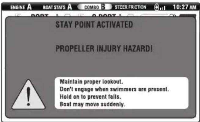
WARNING
- Set-Point automatically operates the engines as needed when the system is engaged to help keep the boat in the set location. Do not use the system when people are in the water or other vessels or obstacles are nearby because of the possibility they could be struck by the propellers or boat when the boat is correcting position. The operator also must be prepared to assume full control at the helm if Set-Point control disengages unexpectedly.
- A rotating propeller, a moving boat, or a device attached to a moving boat can cause serious injury or death to people in the water. When Set-Point is engaged, the propellers rotate and the boat moves to maintain the position of the boat. Stop the engines and disengage Set-Point immediately if anyone enters the water near the boat.
4 modes of Set-Point function
| Mode | High mode | Steering Remarks | |
| Stay PointKeeps bow direction and boat position set automatically when activated.This mode is useful when preparing for docking or waiting near the refueling dock or fishing. | √ | 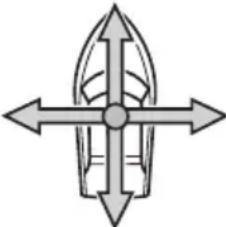  | This mode will only be active on PORT and STBD engines. |
| Fish Point BowKeeps boat position with bow into the wind or current.This mode is useful for fixed point fishing. Shifting and engine rpm is minimized to help avoiding scaring fish from noise. | √ |  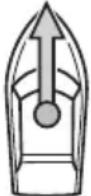   | This mode will only be active on CENTER PORT and CENTER STBD engines. |
Function and operation of components
| Mode | High mode | Steering Remarks | |
| Fish Point SternKeeps boat position with Stern into the wind or current.This mode is useful for fixed point fishing. Shifting and engine rpm is minimized to help avoiding scaring fish from noise. | √ | 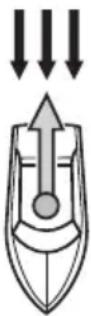 ←A ←B ←A ←B | This mode will only be active on CENTER PORT and CENTER STBD engines. |
| Drift PointKeeps bow direction only and allows lateral movement according to the wind or/and current.This mode is useful for drift fishing or drift cruising. | - | 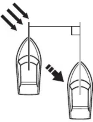  ←B ←B | This mode will be active on CENTER PORT and CENTER STBD engines, or PORT and STBD engines. |
√ : Available
B. Stream/Wind
- : Not available
TIP:
If the boat has been drifted 23 m (25 yd) away from the Stay Point holding position, a popup message will appear, asking if you wish to return to the original holding position.
GPS signal reception level
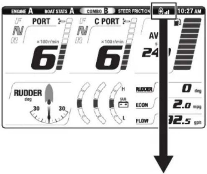
| Set-Point function can be enabled | Cannot be enabled | ||
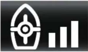 | 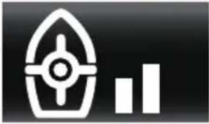 |  |  |
| GPS antenna accuracy | |||
| Within 1 meter Between 1 and 2 meters | Between 2 and 3 meters | Out of 3 meters | |
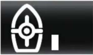
natural_image
Simple icon showing a boat with a cross and an 'X' symbol, no text or labels present.Communication error between the Helm Master system and the GPS Gateway or GPS antenna. When this indicator is lit, the Set-Point function cannot be activated. Consult a Yamaha dealer.
TIP:
The GPS antenna bars will be blinking when the GPS satellite is being searched.
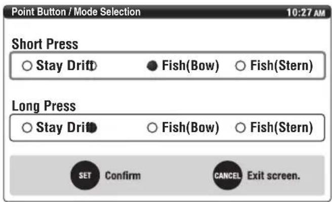
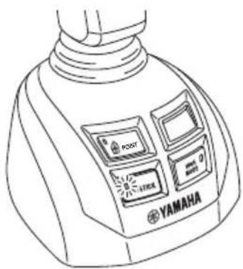
■Mode selection
- From the main menu, select "Point Button".
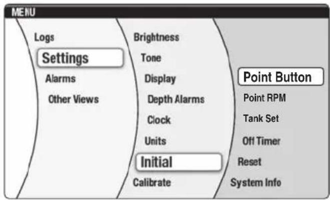
- Select your preferred menu. Press the "SET" button to confirm.
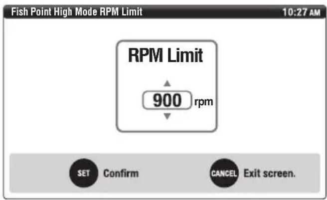
■Setting the maximum engine speed for "High mode" of Fish Point
This function can be adjusted the maximum engine speed for the operating condition in Fish Point mode.
- From the main menu, select "Point RPM".
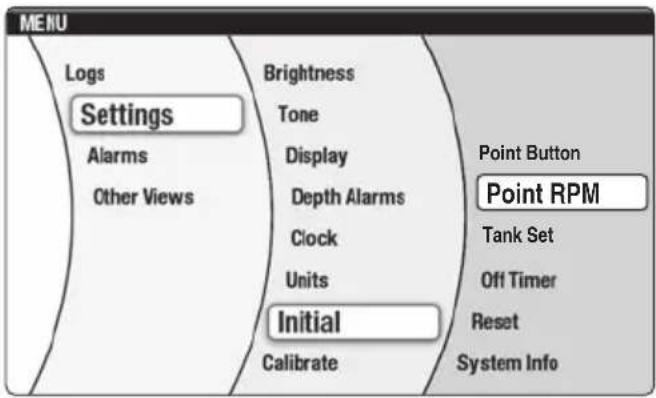
- Use the “▲” and “▼” navigation arrows to select the desired engine speed within the range of 900–2500 r/min. Press the “SET” button to confirm.
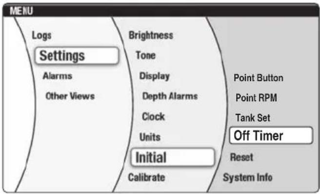
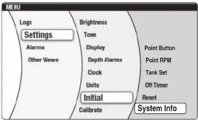
Digital Network Gauge (6Y9)
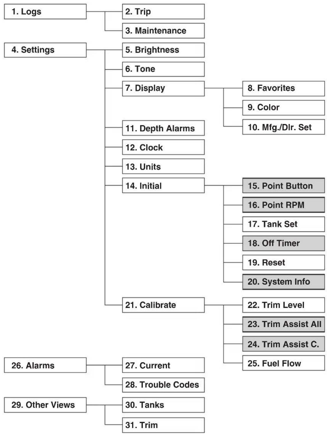
Following is the menu of gauge functions.
TIP:
Refer to the Digital Network Gauge (6Y9) operation manual for the basic operations of the below items with the exception of 15, 16, 18, 20, 23, and 24.
flowchart
graph TD
    A["1. Logs"] --> B["2. Trip"]
    A --> C["3. Maintenance"]
    D["4. Settings"] --> E["5. Brightness"]
    D --> F["6. Tone"]
    D --> G["7. Display"]
    G --> H["8. Favorites"]
    G --> I["9. Color"]
    G --> J["10. Mfg./Dlr. Set"]
    E --> K["11. Depth Alarms"]
    E --> L["12. Clock"]
    E --> M["13. Units"]
    E --> N["14. Initial"]
    N --> O["15. Point Button"]
    N --> P["16. Point RPM"]
    N --> Q["17. Tank Set"]
    N --> R["18. Off Timer"]
    N --> S["19. Reset"]
    N --> T["20. System Info"]
    A --> U["21. Calibrate"]
    U --> V["22. Trim Level"]
    U --> W["23. Trim Assist All"]
    U --> X["24. Trim Assist C."]
    U --> Y["25. Fuel Flow"]
    A --> Z["26. Alarms"]
    Z --> AA["27. Current"]
    Z --> AB["28. Trouble Codes"]
    A --> AC["29. Other Views"]
    AC --> AD["30. Tanks"]
    AC --> AE["31. Trim"]
- Logs
- Trip
- Maintenance
- Settings
- Brightness
- Tone
- Display
- Favorites
- Color
- Mfg./Dlr. Set
- Depth Alarms
- Clock
- Units
- Initial
- Point Button
- Point RPM
- Tank Set
- Off Timer
- Reset
- System Info
- Calibrate
- Trim Level
- Trim Assist All
- Trim Assist C.
- Fuel Flow
- Alarms
- Current
- Trouble Codes
- Other Views
- Tanks
- Trim
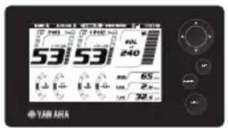
■Twin gauge
Port side gauge displays information on PORT and CENTER PORT engines, and STBD side gauge displays information on STBD and CENTER STBD engines.
A
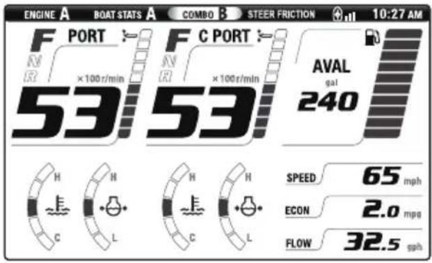
B
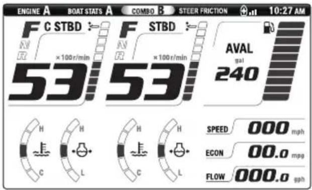
A. PORT side gauge
B. STBD side gauge
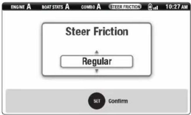
■Steering friction
The steering friction is adjusted automatically according to the engine speed. The steering friction level can be adjusted on the "STEER FUNCTION" screen.
There are two levels of adjustment:
- Regular (default level)
- Heavy
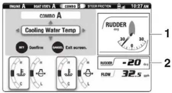
■Rudder angle
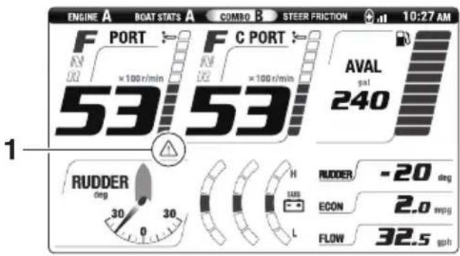
Rudder angle indicates the steering position of the engines during normal steering control. Rudder angle, graphically or numerically, can be selected to display on one of the BOAT STATS or COMBO screens. When rudder angle is displayed numerically, a minus (−) sign indicates the engines are turned to the PORT and a plus (+) sign indicates the engines are turned to the STBD. In joystick mode, the rudder angle will be displayed as 0, regardless of the position of the engines.
BOAT STATS
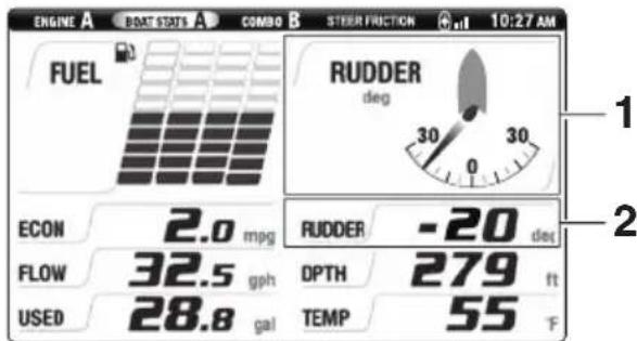
COMBO
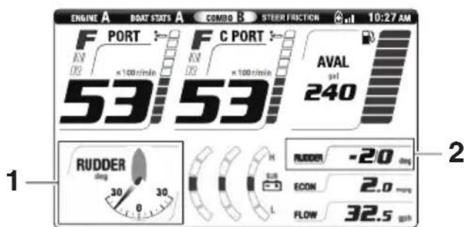
- Graphic rudder angle
- Numeric rudder angle
■Alert display
If a steering system malfunction occurs, a window appears on the Digital Network Gauge (6Y9) display and a buzzer sounds.
TIP:
For message details, see "Alert Notifications" on page 1.
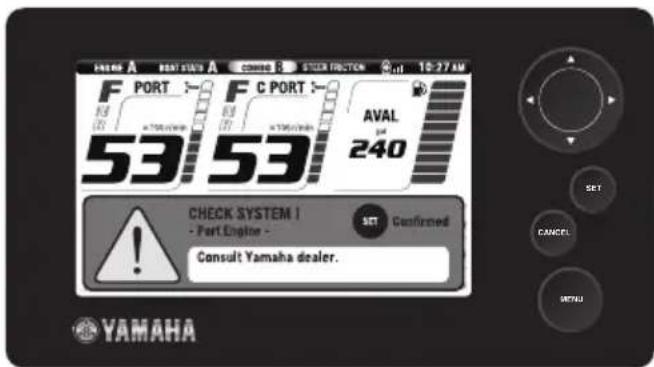
Pressing the "SET" button stops the buzzer (1st press) and closes the window (2nd press). A steering control system trouble alert icon will be displayed in the alert display area of the corresponding engine.
TIP:
- The buzzer also sounds if there is an engine malfunction, as the malfunction may affect boat maneuvering by the Helm Master control system.
- When a warning for water in fuel, engine lanyard switch, overheat, or low oil pressure occurs, the buzzer will not stop until the cause of the warning is corrected even if the "SET" button is pressed.
- Helm Master control system trouble alert
If there are steering control system trouble alerts, contact a Yamaha dealer immediately.
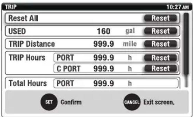
Trip
All "TRIP" information will be reset when using the "Reset All" function. Additionally, each of the items, USED (fuel), TRIP Distance, TRIP Hours, can be reset individually.
TIP:
When “TRIP” information is reset on one gauge, the information of the same item on the other gauge will be reset synchronously.
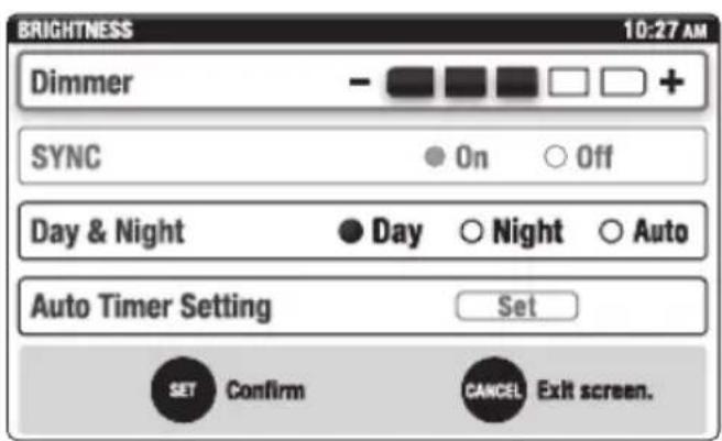
■Brightness
The brightness of the Digital Network Gauge (6Y9) display can be adjusted in 5 levels using the "Dimmer" function. Changing the brightness of the gauge will also change the back lighting of the buttons on the EKS panel, remote control and joystick control. The back lighting of the buttons will be turned OFF if the gauge brightness is set to level 5. Dual station installations: The brightness must be adjusted at each station.
The "Dimmer" is set to level 5 by default.
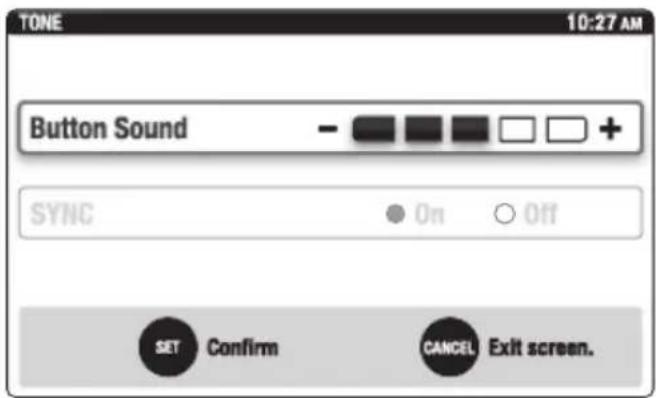
Tone
The sound level emitted when the gauge buttons are pressed can be adjusted using the "Button Sound" function. Dual station installations: The sound must be adjusted at each station.
The "Button Sound" is set to level 3 by default.
■Favorites
Rudder angle is shown in Selection items "1" and "2".
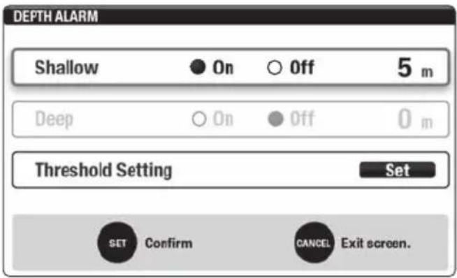
■Depth Alarms
A shallow water alarm can be set to warn when the water depth is less than the minimum set in the gauge (optional Multisensor required). The deep alarm is not functional.
Units
The units for measuring speed, distance, capacities and temperature can be set for either metric or English standards (miles, gallons). American Boating and Yacht Council (ABYC) uses English Standard units.
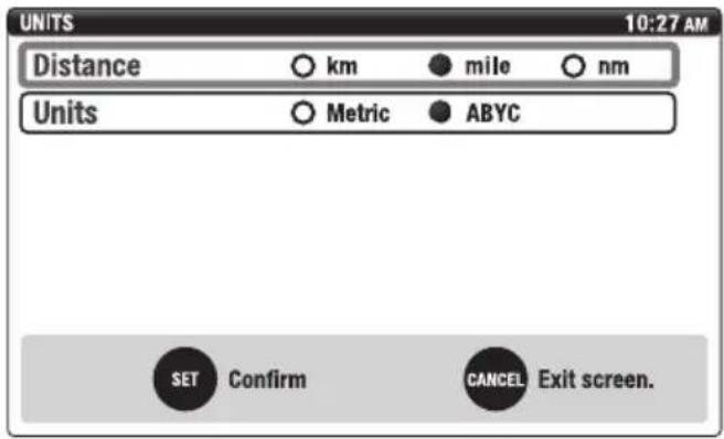
| Distance km mile | nm | ||
| Boat speed km/h | mph knots | ||
| Economy km/L | mpg nm/L |
| Units Metric ABYC | ||
| Fuel L gal | ||
| Fuel flow L/h gph | ||
| Temperature °C | °F | |
| Depth | m | ft |
Tank Set
Either a Single Point or a Multi Point (6 step) calibration can be used when the Digital Network Gauge (6Y9) is used with this steering control system.
Calibration point 1: 0% Calibration point 2: 20% Calibration point 3: 40% Calibration point 4: 60% Calibration point 5: 80% Calibration point 6: 100%
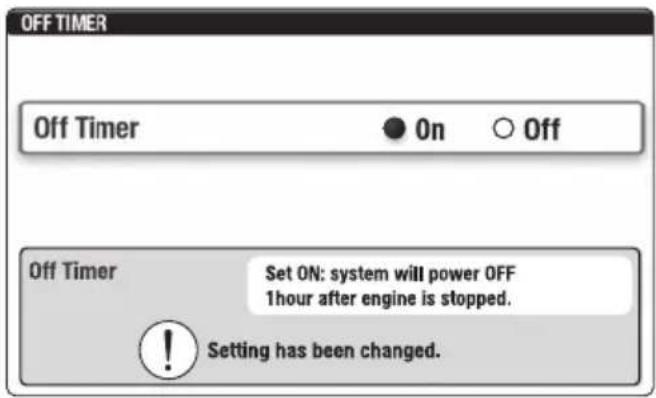
■Off Timer
The "OFF Timer" function will turn OFF the ignition systems for all engines 1 hour after the engines were last stopped using the start/stop switch(es).
TIP:
- The "OFF Timer" does not automatically lock the EKS system. The EKS system must be locked using the EKS fob. Refer to page 12.
- 10 minutes before the ignition turns OFF, a window appears and the buzzer sounds.
-
The default setting of the "OFF Timer" function is OFF.
-
From the main menu, select "Off Timer".
- To activate the timer function, select "On". Press the "SET" button to confirm.
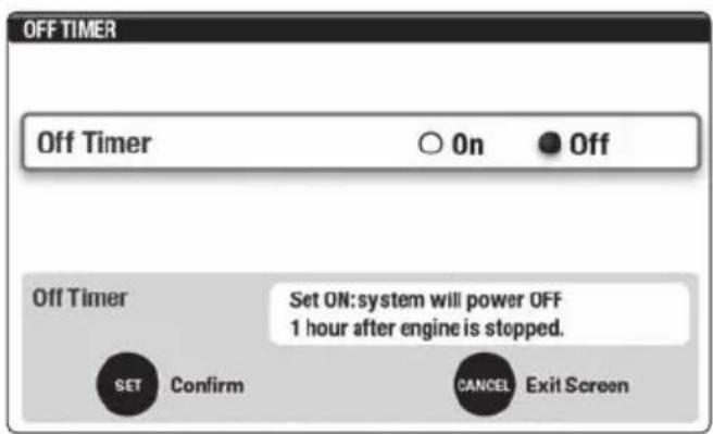
- After approximately 1 second, the display will return to the main menu.
- When the timer is activated a notification window will appear approximately 10 minutes prior to the system being powered down.
■System Info
This function is to show information on the Helm Master control system components mounted on the boat and the software version of the Digital Network gauge (6Y9).
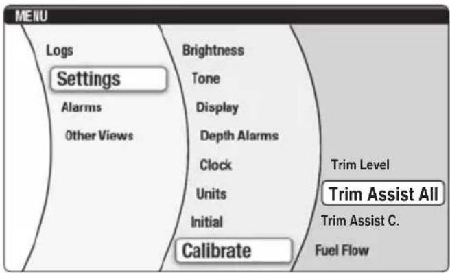
■Trim Assist All
This function automatically sets the outboard motor trim angle according to the engine speed.
- From the main menu, select "Trim Assist All".
TIP:
- There are no default trim assist positions set in a new gauge. The trim assist position settings must be made in order for the trim assist to function.
- Lower the engines to the trim range before starting. Trim assist will not lower the engines until shifted into gear.
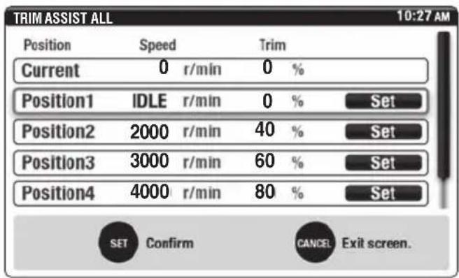
- Use the “▲” and “▼” navigation arrows to choose the position (1-5) you are setting.
TIP:
- The engines must not be running when the desired speed and percentage of trim are entered into the gauge. It is recommended that the boat be water tested to determine the optimum trim positions at specific engine speeds for your operating conditions prior to entering these settings.
- During testing, record the "Current" speed and percentage of trim information for later entry into Positions 1–5.
- It is required to enter engine speed and percentage of trim data in all five positions. Engine speed for Position 1 is automatically set for "Idle".
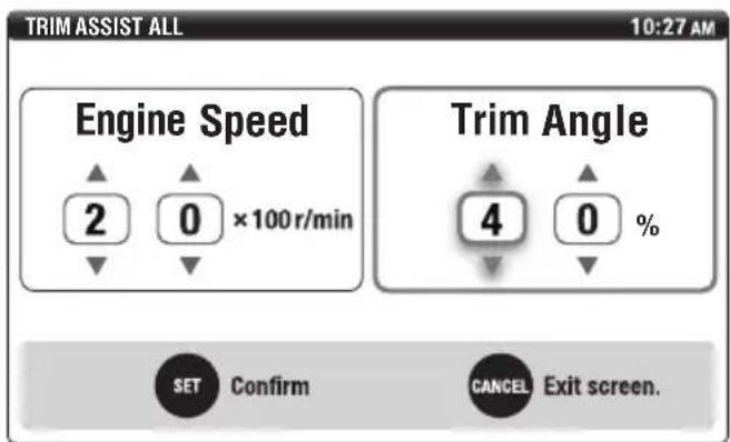
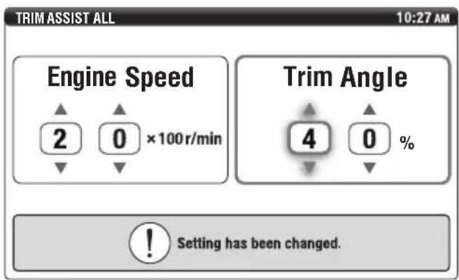
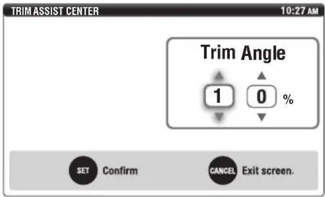
- Use the “▲” and “▼” navigation arrows to set the “Engine Speed”. Use the “▶” navigation arrow to move to the “Trim Angle” setting. Use the “▲” and “▼” navigation arrows to set the amount of trim angle percentage desired. Press the “SET” button to confirm.
TIP:
When setting the Trim angle to 0%, both digits must be set to "0". When setting the Trim angle to 0%, if both digits are not changed from the default setting "--" to "00%" the trim angle will not set when the "SET" button is pressed.
Example:
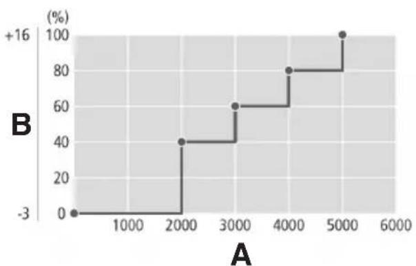
line
| A | B (%) | |---|---| | 0 | 0 | | 2000 | 40 | | 3000 | 60 | | 4000 | 80 | | 5000 | 100 |A. Engine speed (r/min)
B. Trim angle (degrees/percent)
- After approximately 1 second, the display will return to the "Trim Assist All" main menu.
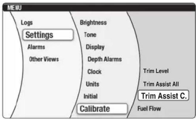
■Trim Assist C.
In some applications when using the automatic trim assist feature, boat performance may be optimal when the CENTER PORT and CENTER STBD outboard motors are synchronously set at trim angles different than the PORT and STBD motors. This function allows the setting of CENTER PORT and CENTER STBD motors' trim angles independent of the trim angles selected when performing the "Trim Assist All" function.
Follow the setting procedure below to configure and enable this function on your boat.
TIP:
To configure and enable "Trim Assist C." function, "Trim Assist All" setting has to be completed first.
- From the main menu, select "Trim Assist C.".
- Use the “▲” and “▼” navigation arrows to choose the position, 1–5, to be adjusted.
Press the "SET" button to confirm.
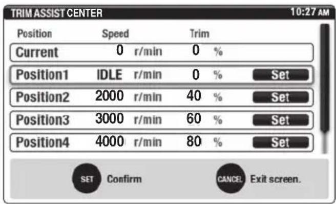
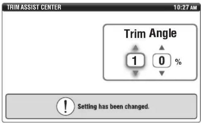
- Use the “▲” and “▼” navigation arrows to set the preferred amount of trim angle shown in percentage.
Press the "SET" button to confirm.
TIP:
The engine speed setting field does not appear. "Trim Assist C." will use the engine speeds previously selected when setting "Trim Assist All".
- The "Setting has been changed." message will appear. The display will return to the "Trim Assist C." main menu in 1 second.
-
To change the percentage of trim angle for the remaining positions, 1–5, repeat steps 2–4.
-
When the trim angles have been set for all desired positions, 1–5, and the display has returned to the "Trim Assist C." main menu, press the "CANCEL" button on the exit.
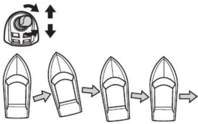
■Joystick calibration
Joystick calibration need only be carried out if boat movements do not correspond to joystick movements.
TIP:
- When calibrating the joystick, the boat must be driven on open waters in safe conditions. Avoid calibrating in high winds or currents that can influence the result of the calibration.
- Allow the boat to run for a fairly long distance during the calibration. Hold the joystick firmly in position.
-
Calibration does not have to be performed in both directions, port and starboard, if only one needs correction.
-
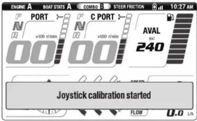
While not in the joystick mode, push and hold the joystick switch for 5 seconds to enter the calibration mode.
natural_image
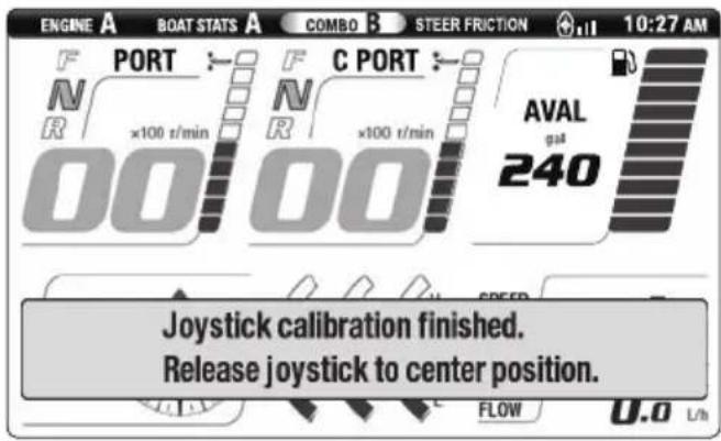
Line drawing of a Yamaha brand blender with front panel and buttons (no text or symbols beyond branding)- A message will appear in the display. Release the joystick switch.
- Move the joystick to STBD. If bow and stern do not move to STBD at the same rate, rotate the joystick to correct. If the boat moves forward or aft, use forward or aft movement of the joystick to correct as necessary.
flowchart
graph LR
    A["Top Box with Inlet"] --> B["Arrow to Top Box"]
    B --> C["Arrow to Bottom Box"]
    C --> D["Arrow to Bottom Box"]
    D --> E["Arrow to Bottom Box"]
- Push the joystick switch again to complete the setting for STBD.
TIP:
If the joystick switch is pressed while the joystick is in the N position, all calibrated settings for the joystick will return to default.
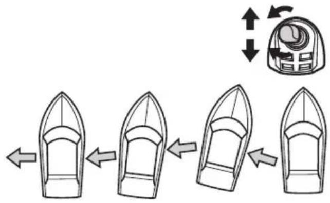
- While not in the joystick mode, push and hold the joystick switch for 5 seconds to enter the calibration mode.
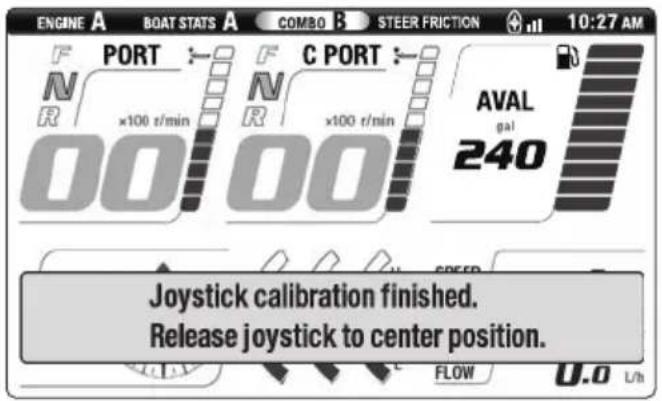
- Move the joystick to PORT. If bow and stern do not move to PORT at the same rate, rotate the joystick to correct. If the boat moves forward or aft, use forward or aft movement of the joystick to correct as necessary.
flowchart
graph LR
    A["Start"] --> B["Step 1"]
    B --> C["Step 2"]
    C --> D["Step 3"]
    D --> E["Step 4"]
- Push the joystick switch again to complete the setting for PORT.
TIP:
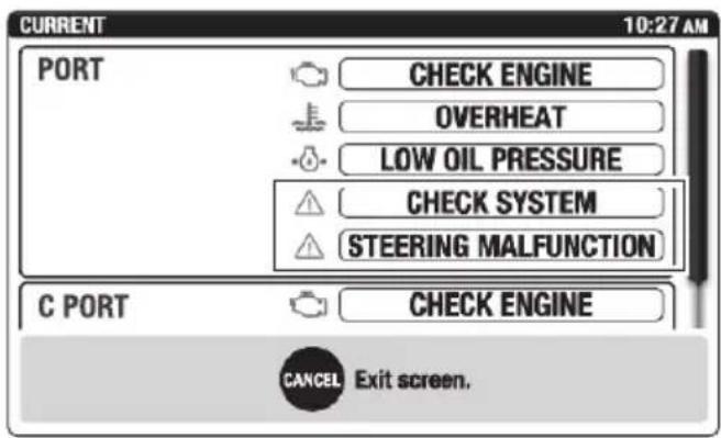
If the joystick switch is pressed while the joystick is in the N position, all calibrated settings for the joystick will return to default.
■Current
"STEERING MALFUNCTION" and "CHECK SYSTEM" warnings are provided. See page 34 for further information.
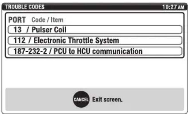
■Trouble Codes
If a malfunction should occur trouble codes and the affected area of the engine(s) or steering system(s) is displayed. Consult a Yamaha dealer.
Function and operation of components
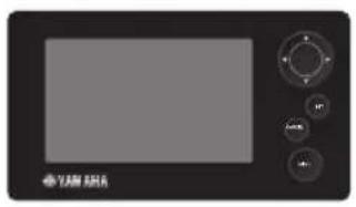
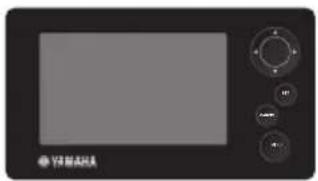
Sleep Mode
If the ignition switches for PORT and CENTER PORT engines are turned off, the PORT display will enter sleep mode and disappear.
natural_image
Front view of a black electronic device with a screen and control buttons (no visible text or symbols)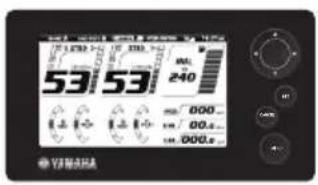
If the ignition switches for STBD and CENTER STBD engines are turned off, the STBD display will enter sleep mode and disappear.
natural_image
Front view of a black industrial control panel with buttons and a screen (no visible text or symbols)Pre-operation checks
Before operating the Helm Master control system, perform the following check. Make sure to turn the ignition switch ON when performing the check.
WARNING
- Do not operate the boat if any Helm Master control system component does not function properly.
- Keep away from the motor-well during the joystick operation. Otherwise, an unexpected steering movement can pinch your body.
| Item Actions | |
| Hydraulic fluid level | ·Check the hydraulic fluid level. See page 45. ·Check whether the level of fluid in the steering pump reservoirs moves up or down when the steering wheel is being turned. Fluctuating fluid level indicates possible air entrapped in the hydraulic system. Contact a Yamaha dealer. |
| Hydraulic fluid leakage | ·Inspect hydraulic hoses and connections. ·Turn steering wheel fully in one direction and then an additional 1/2 turn, and then inspect the connecting section between the steering pumps and power steering cylinders. Also perform checks with the steering wheel turned in the opposite direction. ·Check the hydraulic fluid hoses and connecting sections for wear, twisting, and leaks. ·If there is fluid leakage, it must be repaired before operating the boat. |
| Steering bypass valves | ·Check that the steering bypass valves is closed. See page 45. |
| Electrical component | ·Check that the EKS switch active indicators are illuminated when the ignition switches are turned ON. ·Check that the remote control active indicators are illuminated when the ignition switches are turned ON. ·Place the EKS fob over the lock indicator to check that the EKS panel lock indicator blinks. |
| Controls | ·Turn the steering wheel fully left and fully right. Check that all operating parts function smoothly without any catching or excessive play. Check that the steering responds instantly when the steering wheel is being turned. ·Check the steering control system components for binding, excessive play, wear, and fluid leaks. |
Hydraulic fluid level
Inspect the amount of fluid in the steering pump reservoirs when the steering wheel is being turned. When the fluid level is below the "MIN" mark, replenish until the fluid is between the "MIN" and "MAX" marks.
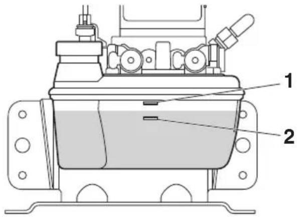
- "MAX" mark
- "MIN" mark
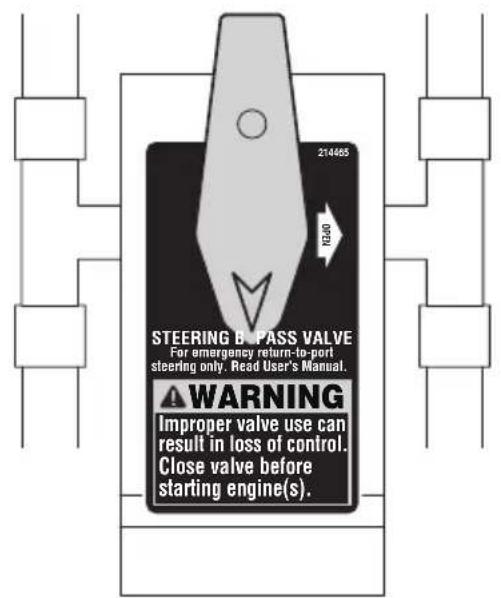
Steering bypass valves
Check that the steering bypass valve is in the closed position.
TIP:
For maintenance and emergency access, have your dealer show you where the steering pumps and/or steering bypass valves are located in the boat.
Temporary actions in emergency
Steering malfunction
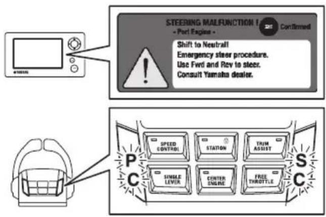
If a steering malfunction occurs, a warning message will appear on the Digital Network Gauge (6Y9) display. This section explains these warnings. If you need additional information, contact your Yamaha dealer.
■One engine's steering does not operate (locked or free)
If one engine's steering does not move as expected the following will occur.
- A display window appears, and a buzzer sounds.
- The remote control alert indicator shows which engine the steering is malfunctioning in.
Example:
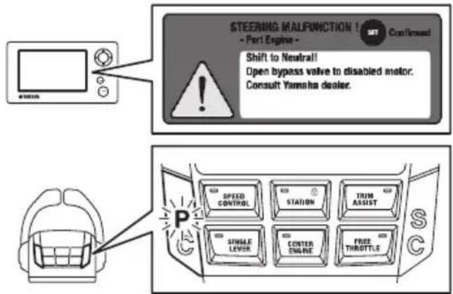
The steering control system shifts all engines into neutral and returns all engines to idle speed. At this time, normal engine steering can only be used within a limited range.
Operators should comply with the following procedures and return to port. After returning to port, please have the unit checked immediately by a Yamaha dealer.
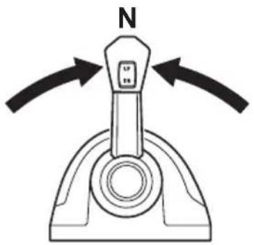
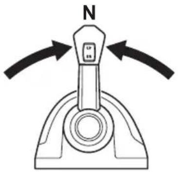
- Place the remote control levers in the N position.
TIP:
Throttle and shift control will not return until the remote control levers are returned to the N position.
- Check the alert messages on the Digital Network Gauge (6Y9) and check which engine is not responding properly to steering input.
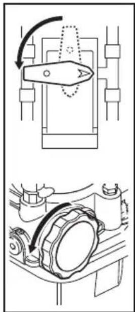
- Open the steering bypass valve of the malfunctioning engine. The engine with the malfunction steering can be manually moved side to side, with minimal effort.
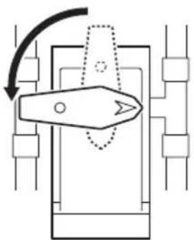
natural_image
Pure mechanical diagram showing a lever mechanism without any text, numbers, or symbols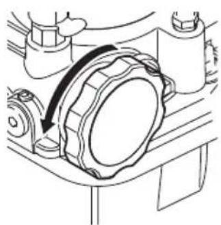
natural_image
Mechanical assembly diagram showing a rotating component with a curved arrow indicating motion (no text or symbols)- The unaffected engine's shift, throttle and steering will operate within the normal parameters. Use the steering and remote control levers to operate the unaffected engine(s) and return to port. Note, the steering response may be sluggish. The affected engine's steering will be moved by the water flowing past the lower unit. The affected engine will remain in neutral even if the shift/throttle lever for that engine is placed in forward (F) or reverse (R).
■All engine's steering do not operate
If all engine's steering do not move as expected the following will occur.
- The display window appears, and a buzzer sounds.
- The remote control alert indicator shows which engine the steering is malfunctioning in.
The steering control system shifts all engines into neutral and returns all engines to idle speed. At this time, all steering will be inoperable.
Operators should comply with the following procedures and return to port. After returning to port, please have the unit checked immediately by a Yamaha dealer.
- Place the remote control levers in the N position.
TIP:
Throttle and shift control will not return until the remote control levers are returned to the N position.
-
Check the alert messages on the Digital Network Gauge (6Y9) and check which engines are not responding properly to steering input.
-
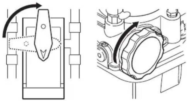
Open all steering bypass valves and manually position all engines so that they are straight.
natural_image
Technical diagram showing mechanical assembly with rotating components and a close-up view of a gear mechanism (no text or labels)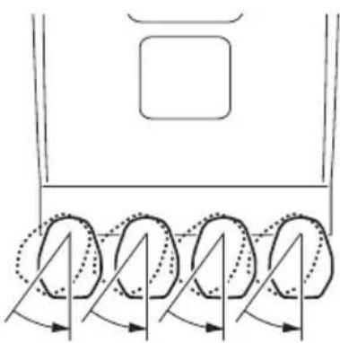
natural_image
Diagram of a vehicle's rearview and side view showing four wheels with motion arrows indicating rotation (no text or symbols)- Close all steering bypass valves.
natural_image
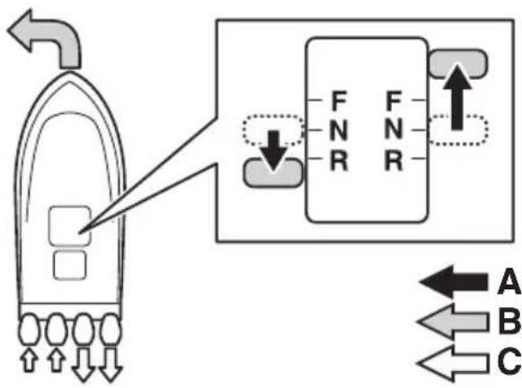
Technical line drawing showing mechanical assembly with no visible text or symbols- While the steering will be inoperable, use the shift and throttle levers for directional control of the boat and return to port.
TIP:
To turn the boat to PORT, place the PORT remote control lever in the R position, and the STDB remote control lever in the F position.
flowchart
graph TD
    A["Boiler"] -->|Flow| B["F N R"]
    B --> C["Port"]
    D["Port"] -->|Flow| E["F N R"]
    E --> F["Port"]
    G["Port"] -->|Flow| H["A"]
    G --> I["B"]
    G --> J["C"]
A. Lever operation
B. Boat direction
C. Propulsion
■Engine interference protection
When the steering control system detects that the steering sensor value does not reach the value requested, the interference safeguard activates, and the following warnings are issued.
- The display window appears, and a buzzer sounds.
- The remote control alert indicator shows which engine the steering is malfunctioning in.
Example:
The steering control system places the gear shifts of all engines in neutral, and sets the engine speed to idle speed. At this time, no engine steering can be used.
Operators should comply with the following procedures and return to port. After returning to port, have the unit checked immediately by a Yamaha dealer.
If a malfunction occurs in remote control mode
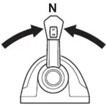
- Place the remote control levers in the N position.
TIP:
Throttle and shift control will not return until the remote control levers are returned to the N position.
natural_image
Diagram of a mechanical lever mechanism with N-axis and directional arrows indicating motion (no text or symbols)- Check the alert messages on the Digital Network Gauge (6Y9) and check which engines are not responding properly to steering input.
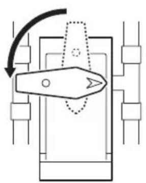
- Open the steering bypass valve of the malfunctioning engine. The malfunctioning engine steering will become free.
natural_image
Pure mechanical diagram showing a lever mechanism with no text or symbols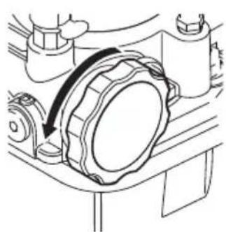
natural_image
Technical line drawing of a mechanical assembly with a curved arrow indicating motion (no text or symbols)- The unaffected engine's shift, throttle and steering will operate within the normal parameters. Use the steering and
remote control levers to operate the unaffected engine(s) and return to port. Note, the steering response may be sluggish. The affected engine's steering will be moved by the water flowing past the lower unit. The affected engine will remain in neutral even if the shift/throttle lever for that engine is placed in forward (F) or reverse (R).
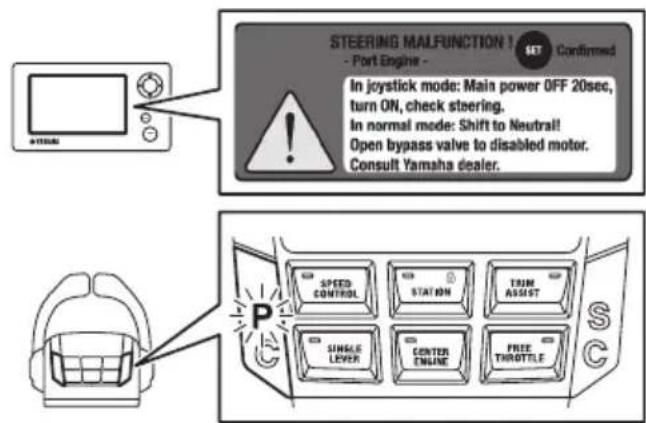
If a malfunction occurs in Joystick mode
- Turn the ignition switches for all engines OFF, and wait for 20 seconds.
- Turn the ignition switches for all engines ON, rotate the steering wheel, and check the movement of the steering.
TIP:
When the steering for more than one engine is malfunctioning, the same warning message appears.
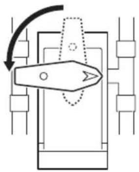
3. Open the steering bypass valves of the malfunctioning engines. The malfunctioning engine steering will become free.
natural_image
Pure mechanical diagram showing a lever mechanism without any text, numbers, or symbols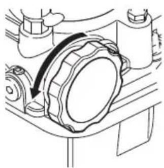
natural_image
Mechanical assembly diagram showing a rotating component with a curved arrow indicating motion (no text or symbols)- The unaffected engine's shift, throttle and steering will operate within the normal parameters. Use the steering and remote control levers to operate the unaffected engine(s) and return to port. Note, the steering response may be sluggish. The affected engine's steering will be moved by the water flowing past the lower unit. The affected engine will remain in neutral even if the shift/throttle lever for that engine is placed in forward (F) or reverse (R).
Periodic maintenance
The following chart provides a basic guideline for the periodic maintenance. However, maintenance may need to be performed more frequently depending on your operating conditions.
Maintenance table
| Item Actions | Initial Every | See page | ||
| 20 hours | 100 hours (6 months) | 200 hours (1 year) | ||
| Hydraulic fluid level | Check the hydraulic fluid level. | √ | √ | 45 |
| Hydraulic fluid leakage | Check for hydraulic fluid leaks. | √ | √ | 44 |
| Hydraulic hoses and connecting sections | Check the hydraulic fluid hoses and connecting sections for wear, twisting, and leaks. | √ | √ | — |
| Steering control system components | Check the steering control system components for tightness, looseness, wear, and leaks. | √ | √ | — |
| Steering cylinder responsiveness | Check whether the steering responds immediately when the steering wheel is turned. | √ | √ | — |
| Steering control system connections* | Check that all steering system fasteners and electrical connectors are tight and secure. Where necessary, tighten fasteners to the correct torque values and electrical connectors are locked. | √ | √ | — |
| Steering and trim/tilt systems* | Check the steering and trim/tilt systems for play. Repair if abnormal play is found. | √ | √ | — |
| Steering system corrosion* | Check the steering control system for signs of corrosion. Contact a Yamaha dealer if any corrosion is found. | √ | √ | — |
| Greasing points* | Apply marine grease. √53 | |||
| Hydraulic fluid* | Perform a visual check to see whether the hydraulic fluid is clean. Clean the fluid if any sediment is found, if water appears to be mixed with the hydraulic fluid, or if there appears to have been a change in color. | √— | ||
*: Items marked with an asterisk must be serviced by a Yamaha dealer.
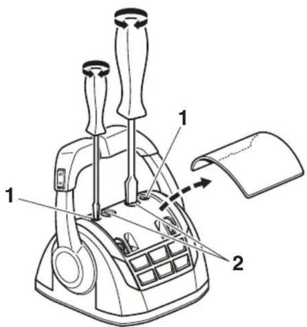
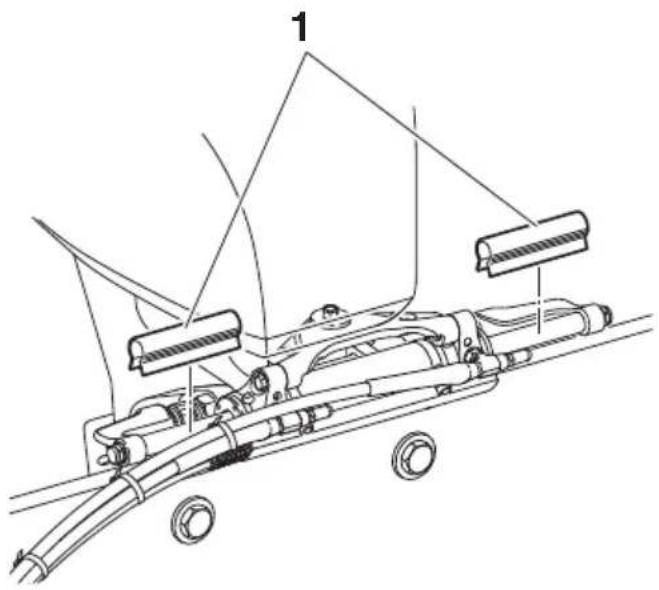
Greasing points
- Remove the PORT and STBD support brackets from the steering cylinder shaft and support rod. Remove the support rod from the tilt tube.
- Clean the support brackets, steering cylinder shaft, support rod, and tilt tube.
- Apply a sufficient amount of grease to the contact points between the support brackets, steering cylinder shaft and the support rod.
- Reassemble the support brackets to the steering cylinder shaft and support rod. Tighten fasteners to the specified torque value.
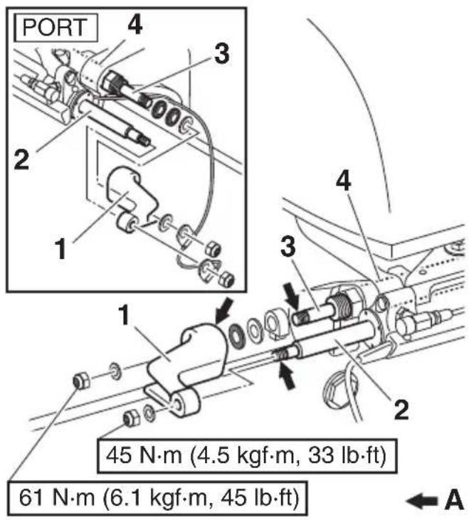
For steering cylinder w/ grease nipples
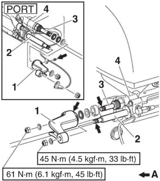
- Support bracket
- Steering cylinder shaft
- Support rod
- Tilt tube
A. Greasing points
Recommended hydraulic fluid
Use the recommended fluids listed below for the steering pump.
NOTICE
Use of any other fluid, including power steering, power trim and tilt, Dexron IV automatic transmission fluid, or brake fluid can cause permanent component damage.
Recommended hydraulic fluid: SeaStar EPS fluid or Chevron MD-3 automatic transmission fluid
Transportation with boat (trailering)
WARNING
- Do not use the service/mooring tilt support levers to support the motors when trailering the boat.
- Ensure steering lock clips are removed BEFORE operating boat. Failure to remove steering lock clips may result in no steering control.
NOTICE
• To prevent unintentional steering movement, secure all motors in the straight ahead position using the steering lock clips.
- To prevent interference between the outboard motors, position all motors straight ahead while using the PTT to tilt only one motor, in and out.
- When trailering the outboard motors in the tilt position, make sure there is sufficient clearance between the outboard motors, including the steering cylinders, and any surfaces of the boat to prevent interference due to shock or vibration during transportation.
The outboard motors should be trailered in the straight ahead direction and normal running position secured with the steering lock clips. If there is insufficient road clearance in this position, tilt and support the outboard motors using Yamaha Trailer Supports or similar devices such as transom savers.
TIP:
If the steering lock clips are damaged or lost, place an order for replacement.
Steering lock clip (2 pcs/set)
Part number: 6ES-23326-00
natural_image
Technical line drawing of a mechanical device with labeled components (no text or symbols present)- Steering lock clip

YAMAHA
- To the operator
- WARNING
- NOTICE
- TIP:
- Alert message information .... 1
- General information 5
- Function and operation of components 11
- Pre-operation checks 44
- Temporary actions in emergency 46
- Periodic maintenance 51
- Transportation with boat (trailering) 54
- Alert message information
- Alert Notifications
- Helm Master control system trouble alert
- Lever sensor calibration alert
- Steering sensor calibration alert
- Auto configuration alert
- One engine steering malfunction alert
- All engines' steering malfunction alert
- Engine interference protection alert
- SCU low battery voltage alert
- SCU high battery voltage alert
- SCU low battery voltage alert (all engines)
- SCU high battery voltage alert (all engines)
- Other Notifications
- Battery low charge alert
- Off timer counting alert
- Shallow water alert
- General information
- List of abbreviations
- Read labels and related manuals
- Warning and caution labels
- SCU (Steering Control Unit)
- ! WARNING
- STEERING BY- PASS VALVE
- STEERING
- BYPASS
- VALVE
- 9
- STEERING CYLINDER
- 10
- Steering sensor extension harness
- EKS
- ■EKS fob
- Lock
- Unlock
- Ignition switch
- ■Start/stop switch
- ■All ignition switch
- ■All start/stop switch
- Engine shut-off switch
- Remote control box
- Function and operation of components
- ■Remote control lever
- ■Lever friction adjuster
- ■Free throttle switch
- ■Single lever switch
- ■Center engine switch
- ■Speed control switch
- ■Station selector switch (for dual station)
- Station lock (dual station only)
- Station lock indicator
- ■Trim assist switch
- ■Power Trim and Tilt (PTT) switch
- ■Remote control active indicator
- ■Remote control alert indicator
- Remote control alert indicator
- Joystick control
- ■Joystick lever
- Maneuvering with the joystick lever
- Joystick switch
- ■High mode switch
- ■Set-Point switch
- Set-Point function
- ■Mode selection
- ■Setting the maximum engine speed for "High mode" of Fish Point
- Digital Network Gauge (6Y9)
- ■Twin gauge
- ■Steering friction
- ■Rudder angle
- ■Alert display
- Trip
- ■Brightness
- Tone
- ■Favorites
- ■Depth Alarms
- Units
- Tank Set
- ■Off Timer
- ■System Info
- ■Trim Assist All
- ■Trim Assist C.
- ■Joystick calibration
- ■Current
- ■Trouble Codes
- Sleep Mode
- Pre-operation checks
- Hydraulic fluid level
- Steering bypass valves
- Temporary actions in emergency
- Steering malfunction
- ■One engine's steering does not operate (locked or free)
- ■All engine's steering do not operate
- ■Engine interference protection
- If a malfunction occurs in remote control mode
- If a malfunction occurs in Joystick mode
- Periodic maintenance
- Greasing points
- Recommended hydraulic fluid
- Transportation with boat (trailering)
- YAMAHA
Brand : YAMAHA
Model : Heml Master (2017)
Category : Outboard motor