
F115A - Outboard motor YAMAHA - Free user manual and instructions
Find the device manual for free F115A YAMAHA in PDF.


| Product Type | 4-stroke outboard motor |
| Brand | Yamaha |
| Model | F115A |
| Maximum power | 115 hp (85 kW) at 5500 rpm |
| Displacement | 1,740 cm³ |
| Fuel | Unleaded gasoline |
| Starting system | Electric |
| Dry weight (without propeller) | 163 kg |
| Overall length | 762 mm |
| Overall width | 411 mm |
| Overall height | 1,115 mm |
| Transom height | 508 mm (20 inches) |
| Engine oil capacity | 4.5 L |
| Fuel tank capacity | External (not supplied) |
| Gear ratio | 2.15:1 |
| Standard propeller | 3-blade aluminum |
| Cooling system | Water-cooled with centrifugal pump |
| Ignition | Electronic CDI |
| Alternator | 12V - 15A |
| Safety | Emergency stop switch (kill switch) |
| Main functions | Speed control, steering, power trim and tilt (optional) |
| Routine maintenance | Oil change, oil filter replacement, zinc anode |
| Cleaning | Freshwater flush after saltwater use |
| Spare parts | Available from Yamaha dealers or official website |
Frequently Asked Questions - F115A YAMAHA
User questions about F115A YAMAHA
0 question about this device. Answer the ones you know or ask your own.
Ask a new question about this device
Download the instructions for your Outboard motor in PDF format for free! Find your manual F115A - YAMAHA and take your electronic device back in hand. On this page are published all the documents necessary for the use of your device. F115A by YAMAHA.
USER MANUAL F115A YAMAHA
natural_image
Abstract white geometric shape on black background, resembling a stylized letter or symbol (no text or symbols present)WORLDWIDE
F115A
FL115A
USA, CANADA
F115Y
LF115Y
E SERVICE MANUAL
F MANUEL D'ENTRETIEN
D WARTONGSHANDBUCH
ES MANUAL DE SERVICIO
290381
68V-28197-ZA-C1
PREFACE
This manual has been prepared by the Yamaha Motor Company, Ltd. primarily for use by Yamaha dealers and their trained mechanics when performing maintenance procedures and repairs to Yamaha equipment. It has been written to suit the needs of persons who have a basic understanding of the mechanical and electrical concepts and procedures inherent in the work, for without such knowledge attempted repairs or service to the equipment could render it unsafe or unfit for use.
Because the Yamaha Motor Company, Ltd. has a policy of continuously improving its products, models may differ in detail from the descriptions and illustrations given in this publication. Use only the latest edition of this manual. Authorized Yamaha dealers are notified periodically of modifications and significant changes in specifications and procedures, and these are incorporated in successive editions of this manual.
F115A/FL115A
SERVICE MANUAL
©2000 Yamaha Motor Co., Ltd.
1st Edition, January 2000
All rights reserved.
No part of this publication may be
reproduced or transmitted in any form or by
any means including photocopying and
recording without the written permission of the copyright holder.
Such written permission must also be
obtained before any part of this publication
is stored in a retrieval system of any nature.
Printed in Japan
P/N 68V-28197-ZA-C1
PREFACE
HOW TO USE THIS MANUAL
MANUAL FORMAT
All of the procedures in this manual are organized in a sequential, step-by-step format. The information has been compiled to provide the mechanic with an easy to read, handy reference that contains comprehensive explanations of all disassembly, repair, assembly, and inspection operations.
For instance, the condition of a faulty component will precede an arrow symbol and the course of action required will follow the symbol.
- Bearings
Pitting/scratches → Replace.
To assist you in finding your way through this manual, the section title and major heading is given at the top of every page.
MODEL INDICATION
Multiple models are mentioned in this manual and their model indications are noted as follows.
| Model name F115AET FL115AET | |
| USA and Canada name | F115TR LF115TR |
| Indication F115AET FL115AET |
ILLUSTRATIONS
The illustrations within this service manual represent all of the designated models.
CROSS REFERENCES
The cross references have been kept to a minimum. Cross references will direct you to the appropriate section or chapter.
STRUCTURE DU MANUEL
FORMAT DU MANUEL
CÓMO EMPLEAR ESTE MANUAL
FORMATO DEL MANUAL
In this Service Manual particularly important information is distinguished in the following ways.

The Safety Alert Symbol means ATTENTION! BECOME ALERT! YOUR SAFETY IS INVOLVED!

WARNING
Failure to follow WARNING instructions could result in severe injury or death to the machine operator, a bystander, or a person inspecting or repairing the outboard motor.
CAUTION:
A CAUTION indicates special precautions that must be taken to avoid damage to the outboard motor.
NOTE:
A NOTE provides key information to make procedures easier or clearer.
F
D
ES
INFORMATIONS IMPORTANTES
HOW TO USE THIS MANUAL
① The main points regarding removing/installing and disassembling/assembling procedures are shown in the exploded views.
② The numbers in the exploded views indicate the required sequence of the procedure and should be observed accordingly.
③ Symbols are used in the exploded views to indicate important aspects of the procedure. A list of meanings for these symbols is provided on the following page.
④ It is important to refer to the job instruction charts at the same time as the exploded views. These charts list the sequence that the procedures should be carried out in, as well as providing explanations on part names, quantities, dimensions and important points relating to each relevant task.
Example:
O-ring size 39.5
⑤ In addition to tightening torques, the dimensions of the bolts and screws are also mentioned.
Example:
Bolt and screw size : both and screw diameter (D)
- length (L)
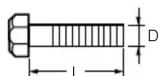
⑥ In addition to the exploded views and job instruction charts, this manual provides individual illustrations when further explanations are required to explain the relevant procedure.

STRUCTURE DU MANUEL
CÓMO EMPLEAR ESTE MANUAL
Symbols ① to ⑨ are designed as thumb-tabs to indicate the content of a chapter.
① General information
② Specifications
③ Periodic inspections and adjustments
④ Fuel system
⑤ Power unit
⑥ Lower unit
⑦ Bracket unit
⑧ Electrical systems
⑨ Trouble analysis
Symbols ⑩ to ⑮ indicate specific data.
⑩ Special tool
⑪ Specified liquid
⑫ Specified engine speed
⑬ Specified torque
⑭ Specified measurement
⑮ Specified electrical value
[Resistance (Ω), Voltage (V), Electric current (A)]
Symbol ⑯ to ⑱ in an exploded diagram indicate the grade of lubricant and the location of the lubrication point.
⑯ Apply Yamaha 4-stroke outboard motor oil (TC-W3)
⑰ Apply water resistant grease (Yamaha grease A, Yamaha marine grease)
⑱ Apply molybdenum disulfide oil
Symbols ⑲ to ⑳ in an exploded diagram indicate the grade of the sealing or locking agent and the location of the application point.
⑲ Apply Gasket Maker®
⑳ Apply Yamabond #4 (Yamaha bond number 4)
②1 Apply LOCTITE® No. 271 (Red LOCTITE)
② Apply LOCTITE® No. 242 (Blue LOCTITE)
②3 Apply LOCTITE® No. 572
②4 Apply silicon sealant
SYMBOLES
PERIODIC INSPECTIONS AND ADJUSTMENTS
FUEL SYSTEM
POWER UNIT
LOWER UNIT
BRACKET UNIT
ELECTRICAL SYSTEMS
TROUBLE ANALYSIS
| TABLE DES MATIERES | INHALT | TABLA DE MATERIAS | |
| INFORMATIONS GENERALES | ALLGEMEINES | INFORMACIÓN GENERAL |  1 1 |
| SPECIFICATIONS | TECHNISCHE DATEN | ESPECIFICACIONES |  2 2 |
| INSPECTION PERIODIQUE ET REGLAGE | REGELMÄBIGE INSPEKTIONEN UND EINSTELLUNGEN | INSPECCIÓN PERIÓDICA Y AJUSTE |  3 3 |
| SYSTEME D'ALIMENTATION | KRAFTSTOFFAN-LAGE | SISTEMA DE COMBUSTIBLE |  4FUEL 4FUEL |
| MOTEUR | MOTOR | MOTOR |  5POWR 5POWR |
| BLOC DE PROPULSION | ANTRIEBSEINHEIT | UNIDAD INFERIOR |  6LOWR 6LOWR |
| UNITE DE SUPPORT | MOTORHALTERUNG | UNIDAD DE MÉNSULA |  7BRKT 7BRKT |
| EQUIPEMENT ELECTRIQUE | ELEKTRISCHE ANLAGE | SISTEMAS ELÉCTRICOS |  8ELEC 8ELEC |
| DEPANNAGE | STÖRUNGSSUCHE | ANÁLISIS DE AVERÍAS |  9 9 |
CHAPTER 1 GENERAL INFORMATION
IDENTIFICATION 1-1
SERIAL NUMBER 1-1
STARTING SERIAL NUMBERS 1-1
SAFETY WHILE WORKING 1-2
FIRE PREVENTION 1-2
VENTILATION.... 1-2
SELF-PROTECTION.... 1-2
OILS, GREASES AND SEALING FLUIDS.... 1-2
GOOD WORKING PRACTICES 1-3
DISASSEMBLY AND ASSEMBLY 1-4
SPECIAL TOOLS 1-5
MEASURING 1-5
REMOVING AND INSTALLING 1-7
CHAPITRE 1 INFORMATIONS GENERALES
IDENTIFICATION....1-1
NUMERO DE SERIE ...... 1-1
NUMEROS DE DEBUT DE SERIE ....1-1
MESURES DE SECURITE EN
TRAVAILLANT 1-2
MESURES CONTRE LES INCENDIES ....1-2
VENTILATION....1-2
PROTECTION PERSONNELLE.....1-2
HUILES, GRAISSES ET LIQUIDES D'ETANCHEITE......1-2
BONNES PRATIQUES DE TRAVAIL....1-3
DEMONTAGE ET REMONTAGE..1-4
OUTILLAGE SPECIAL ....1-5
MESURE....1-5 DEPOSE ET INSTALLATION....1-7
natural_image
Technical line drawing of a mechanical device with a digital display and directional arrow (no text or symbols)
IDENTIFICATION SERIAL NUMBER
The outboard motor's serial number is stamped on a label which is attached to the port side of the clamp bracket.
NOTE:
If the serial number label is removed, "VOID" marks will be appear on the label.
① Model name
② Approved model code
③ Transom height
④ Serial number
STARTING SERIAL NUMBERS
The starting serial number blocks are as follows:
| Model name | Approved model code | Starting serial number | ||
| World-wide | USA Canada | |||
| F115AET F | 115TR F115 | TR 68V | L: 300101 - | |
| X: 700101 - | ||||
| FL115AET | LF115TR LF | 115TR 68W | X: 800101 - | |
IDENTIFICATION
NUMERO DE SERIE
SAFETY WHILE WORKING
The procedures given in this manual are those recommended by Yamaha to be followed by Yamaha dealers and their mechanics.

natural_image
Illustration of a worker in uniform operating a large cylindrical device with a chimney emitting smoke (no text or symbols)
natural_image
Illustration of a person operating a staircase with a large fan and ventilation system, no text or symbols present
natural_image
Line drawing of a worker operating a grinding machine with a tool (no text or symbols)
natural_image
Line drawing of a worker holding a tablet and standing at a table with books (no text or symbols)FIRE PREVENTION
Gasoline (petrol) is highly flammable.
Petroleum vapor is explosive if ignited.
Do not smoke while handling gasoline and keep it away from heat, sparks and open flames.
VENTILATION
Petroleum vapor is heavier than air and is deadly if inhaled in large quantities. Engine exhaust gases are harmful to breathe.
When test-running an engine indoors, maintain good ventilation.
SELF-PROTECTION
Protect your eyes with suitable safety glasses or safety goggles, when grinding or when doing any operation which may cause particles to fly off. Protect hands and feet by wearing safety gloves or protective shoes if appropriate to the work you are doing.
OILS, GREASES AND SEALING FLUIDS
Use only genuine Yamaha oils, greases and sealing fluids or those recommended by Yamaha.
MESURES DE SECURITE EN TRAVAILLANT
Under normal conditions of use, there should be no hazards from the use of the lubricants mentioned in this manual, but safety is all-important, and by adopting good safety practices, any risk is minimized. A summary of the most important precautions is as follows:
- While working, maintain good standards of personal and industrial hygiene.
- Clothing which has become contaminated with lubricants should be changed as soon as practicable, and laundered before further use.
- Avoid skin contact with lubricants; do not, for example, place a soiled wiping-rag in your pocket.
- Hands and any other part of the body which have been in contact with lubricants or lubricant-contaminated clothing, should be thoroughly washed with hot water and soap as soon as practicable.
- To protect the skin, the application of a suitable barrier cream to the hands before working, is recommended.
- A supply of clean lint-free cloths should be available for wiping purposes.

natural_image
Line drawing of a worker operating a lathe machine (no text or symbols)GOOD WORKING PRACTICES
1. The right tools
Use the recommended special tools to protect parts from damage. Use the right tool in the right manner – do not improvise.
2. Tightening torque
Follow the tightening torque instructions. When tightening bolts, nuts and screws, tighten the large sizes first, and tighten inner-positioned fixings before outer-positioned ones.
GEN INFO

natural_image
Illustration of a worker operating machinery with sparkles (no text or symbols)
natural_image
Illustration of a mechanic working on a mechanical tool, surrounded by tools and components (no text or symbols)
natural_image
Line drawing of a worker operating a lathe machine (no text or symbols)- Non-reusable items
Always use new gaskets, packings, O-rings, split-pins, circlips, etc., on reassembly.
DISASSEMBLY AND ASSEMBLY
-
Clean parts with compressed air when disassembling.
-
Oil the contact surfaces of moving parts before assembly.
-
After assembly, check that moving parts operate normally.
-
Install bearings with the manufacturer's markings on the side exposed to view, and liberally oil the bearings.
-
When installing oil seals, apply a light coating of water-resistant grease to the outside diameter.
GEN INFO

MESURES DE SECURITE EN TRAVAILLANT
Using the correct special tools recommended by Yamaha, will aid the work and enable accurate assembly and tune-up. Improvising and using improper tools can damage the equipment.
NOTE:
- For U.S.A. and Canada, use part numbers that start with "J-", "YB-", "YM-", "YU-" or "YW-".
- For others countries, use part numbers that start with "90890-".
①
②

③
④

⑤

⑥
⑦

⑧
⑨
⑩

MEASURING
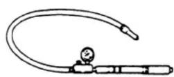
① Pressure tester
P/N. YB-35956
90890-06762
② Mity vac
P/N. YB-35956
90890-06756
③ Pinion height gauge
P/N. YB-34432-6, YB-34432-11,
YB-34432-97
90890-06702
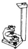
④ Dial gauge set
P/N. YU-03097
90890-01252
⑤ Magnetic base
P/N. YU-34481
90890-06705
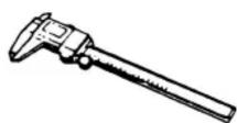
⑥ Digital caliper
P/N. 90890-06704
⑦ Backlash indicator
P/N. YB-06265
90890-06706
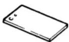
⑧ Magnetic base attaching plate
P/N. YB-07003
90890-07003
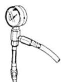
⑨ Fuel pressure gauge
P/N. YB-06766
90890-06786
⑩ Hydraulic pressure gauge
P/N. 90890-06776
OUTILLAGE SPECIAL
natural_image
Line drawing of a U-shaped pipe fitting with two connectors (no text or symbols)⑮

⑯

⑰
⑱

⑲


⑪ Up-relief valve attachment
P/N. 90890-06773
Down-relief valve attachment
P/N. 90890-06774
⑫ Digital tester
P/N. J-39299
90890-06752
⑬ Peak voltage adapter
P/N. YU-39991 ...... ⓐ
90890-03169 ...... ⓑ
⑭ Spark gap tester
P/N. YM-34487 ...... ⓐ
90890-06754 ...... ⓑ
⑮ Shimming gauge
P/N. YB-34446-1, YB-34446-3,
YB-34446-5, YB-34446-7
⑯ Shimming gauge
P/N. YB-34468-2
⑰ Shimming plate
P/N. 90890-06701
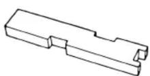
⑱ Shift rod wrench
P/N. YB-06052
90890-06052
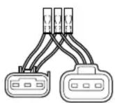
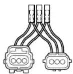
⑲ Test harness
P/N. 90890-06790, 90890-06791,
90890-06792, 90890-06793
GEN INFO

REMOVING AND INSTALLING
① Flywheel magnet assembly holder P/N. YB-06139 ...... a 90890-06522 ...... b
② Universal puller P/N. YB-06117 ..... a 90890-06521 ..... b
③ Bearing/oil seal attachment P/N. YB-06196 ...... a 90890-06653 ...... b
④ Driver rod P/N. YB-06071 90890-06602, 90890-06604, 90890-06605, 90890-06606, 90890-06652
⑤ Bearing/oil seal attachment P/N. YB-06430 90890-06630, 90890-06656
⑥ Bearing/oil seal attachment P/N. YB-06199 90890-06620
⑦ Piston ring compressor P/N. YU-33294 ..... a 90890-06530 ..... b
⑧ Bearing separator P/N. YB-06219 ...... a 90890-06534 ...... b
⑨ Guide plate stand P/N. 90890-06538
⑩ Guide plate P/N. 90890-06501
DEPOSE ET INSTALLATION
⑫ Bearing/oil seal attachment
P/N. 90890-06661
⑬ Ring nut wrench
P/N. YB-34447
90890-06511
⑭ Ring nut wrench extension
P/N. 90890-06513
⑮ Propeller shaft housing puller
P/N. YB-06207 ...... ⓐ
90890-06502 ...... ⓑ
⑯ Center bolt
P/N. 90890-06504
⑰ Slide hammer
P/N. YB-06096
90890-06531
⑱ Small universal claws
P/N. 90890-06536
⑲ Bearing/oil seal depth plate
P/N. YB-06213, YB-34474 ...... ⓐ
90890-06603 ...... ⓑ
⑳ Drive shaft holder
P/N. YB-06151
90890-06519
②1 Pinion nut holder
P/N. 90890-06505
②2 Pinion nut holder attachment
P/N. 90890-06507
②3 Bearing/oil seal attachment
P/N. YB-06194, YB-06195,
YB-06200, YB-06376,
YB-06337, YB-06378
90890-06607, 90890-06608,
90890-06610, 90890-06612,
90890-06636
⑳ Bearing puller
P/N. 90890-06523
⑲ Large universal claws
P/N. 90890-06532
GEN INFO

natural_image
Line drawing of a mechanical clamp or clamping device with no text or symbols③1

③2
a
natural_image
Illustration of a mechanical tool kit with multiple circular components and adjustment knobs (no text or labels visible)b

natural_image
Illustration of a mechanical tool with four cylindrical components, no text or symbols present③3

③4


natural_image
Simple line drawing of a cylindrical object with a protruding shaft (no text or symbols)③6
natural_image
Line drawing of a pen or writing instrument with a pointed tip and cylindrical body (no text or symbols)③7

②6 Slide hammer attachment
P/N. YB-06335
90890-06514
⑳ Oil filter wrench
P/N. YU-38411
90890-01426
⑳ End screw wrench
P/N. YB-06175-1A
⑲ End screw wrench
P/N. YB-06548
90890-06548
③0 Valve spring compressor
P/N. YM-01253
90890-04019
③1 Valve spring compressor adapter
(∅22 mm)
P/N. YB-06554
90890-06554
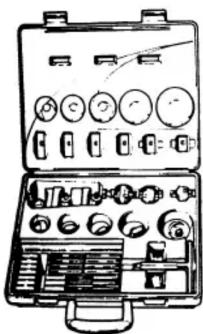
③2 Valve seat cutter set
P/N. YM-91043-C......①
90890-06803 ...... ⓑ
③3 Valve seat cutter holder ( 6 mm)
P/N. YB-06553
90890-06553
③4 Valve seat cutter
P/N. YB-06555 (45° - 30 mm)
YB-06556 (90° - 30 mm)
90890-06555 (45° - 30 mm)
90890-06556 (90° - 30 mm)
③5 Valve guide remover ( 5.9 mm)
P/N. YM-4064-A
90890-04064
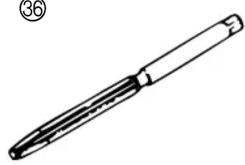
③6 Valve guide reamer ( 6 mm)
P/N. YM-04066
90890-04066
③7 Crankshaft holder
P/N. YB-06552
90890-06552
GEN INFO

| Item Unit | 115AET FL115TR LF115TR | Model | ||
| 5AET | ||||
| DIMENSION | ||||
| Overall length mm (in) 825 (32.5) | ||||
| Overall width mm (in) 498 (19.6) | ||||
| Overall height | ||||
| (L) mm (in) 1,609 (63.3) — | ||||
| (X) mm (in) 1,736 (68.3) | ||||
| Boat transom height | ||||
| (L) mm (in) 516 (20.3) — | ||||
| (X) mm (in) 643 (25.3) | ||||
| WEIGHT(with aluminum propeller) | ||||
| (L) | kg (lb) | 192 (422.4) | — | |
| (X) | kg (lb) 197 (433.4) | |||
| PERFORMANCE | ||||
| Maximum output | kW (hp) @ 5,500 r/min | 84.6 (115) | ||
| Full throttle operating range | r/min | 5,000 - 6,000 | ||
| Maximum fuel consumption | L (US gal, Imp gal)/hr @ 5,500 r/min | 38 (10.0, 8.4) | ||
| POWER UNIT | ||||
| Type | In-line, 4 stroke, DOHC, 16 valves | |||
| Number of cylinders | 4 | |||
| Displacement | cm3 (cu. in) | 1,741 (106.2) | ||
| Bore · stroke mm (in) | 79.0 | · 88.8 (3.11 · 3.50) | ||
| Compression ratio | 9.7 | |||
| Minimum compression pressure | kPa(kgf/cm2, psi) | 950 (9.5, 135) | ||
| Fuel system | Electronic fuel injection | |||
| Fuel injection system | Group injection | |||
| Starting system | Electric | |||
| Ignition control system | Microcomputer (TCI) | |||
| Alternator output | 12 - 25A | |||
| Spark plugs (NGK) | LFR6A-11 | |||
| Cooling system | Water | |||
| Exhaust system | Through propeller boss | |||
| Lubrication system | Wet sump | |||
| Lubrication oil pressure at 65°C (149°F), with low-30 engine oil | kPa(kgf/cm2, psi)@ 850 r/min | 320 (3.2, 45.5) | ||
SPECIFICATIONS GENERALES
| Item | Worldwide | Unit | Model | |
| F115AET | FL115AET | |||
| USA | F115TR | LF115TR | ||
| Canada | F115TR | LF115TR | ||
| FUEL AND OIL | ||||
| Fuel type Unleaded regular gasoline | ||||
| Fuel rating *PON | 86 | |||
| Engine oil type 4-stroke outboard engine oil | ||||
| Engine oil grade API | SE, SF, SG, SH | |||
| Engine oil capacity (with oil filter) cm | SAE | 10W-30, 10W-40 | ||
| (without oil filter) cm | ^3 (US oz, Imp oz) | 4,700 (159, 165) | ||
| Gear oil type Hypoid gear oil | ^3 (US oz, Imp oz) | 4,500 (152, 158) | ||
| Gear oil grade API | GL-4 | |||
| Gear oil total quantity cm | SAE | 90 | ||
| ^3 (US oz, Imp oz) | 760 (25.7, 26.8) 715 | (24.2, 25.2) | ||
| BRACKET | ||||
| Trim angle (at 12° boat transom) | Degree -4 | - 16 | ||
| Tilt-up angle Degree 70 | ||||
| Steering angle Degree 30 + 30 | ||||
| DRIVE UNIT | ||||
| Gear shift positions | F-N-R | |||
| Gear ratio | 2.15 (28/13) | |||
| Reduction gear type | Spiral bevel gear | |||
| Clutch type | Dog clutch | |||
| Propeller shaft type | Spline | |||
| Propeller direction (rear view) | Clockwise | Counterclockwise | ||
| Propeller mark | K | KL | ||
| ELECTRICAL | ||||
| Battery capacity | Ah (kC) 70 | - 100 (252 - 360) | ||
| Minimum cold cranking performance | A | 380 | ||
* PON: Pump Octane Number (Research octane + Motor octane)/2
RON: Research Octane Number
| Item Unit | F115AET FL115TR | Model | ||
| 5AET | ||||
| LF115TR | ||||
| F115TR | LF115TR | |||
| IGNITION SYSTEM | Degree | 4 ATDC - 26 BTDC | ||
| Ignition timing | ||||
| CDI unit (B/R, B/W – B) | ||||
| Output peak voltage lower limit | ||||
| @ cranking 1 | V | 5.0 | ||
| @ cranking 2 | V | 122 | ||
| @ 1,500 r/min | V | 242 | ||
| @ 3,500 r/min | V | 245 | ||
| Pulser coil (W/R, W/B – B) | ||||
| Output peak voltage lower limit | ||||
| @ cranking 1 | V | 3.5 | ||
| @ cranking 2 | V | 3.0 | ||
| @ 1,500 r/min | V | 26 | ||
| @ 3,500 r/min | V | 44 | ||
| IGNITION CONTROL SYSTEM | ||||
| Engine cooling water temperature sensor | ||||
| Resistance (B/Y – B) | ||||
| @ 5°C (41°F) | kΩ | 4.62 | ||
| @ 20°C (68°F) | kΩ | 2.44 | ||
| @ 100°C (212°F) | kΩ | 0.19 | ||
| Throttle position sensor | ||||
| Output voltage (P – B) | V | 0.732 ± 0.014 | ||
* Cranking 1: Open circuit voltage.
Cranking 2: Loaded circuit voltage.
BLOC DE PROPULSION
| Item | Worldwide | Unit | Model | |
| F115AET | FL115AET | |||
| USA | F115TR | LF115TR | ||
| Canada | F115TR | LF115TR | ||
| STARTING SYSTEMFuse 1 V-A 12-20Fuse 2 V-A 12-30 | ||||
| STARTER MOTORType Sliding gearOutput kW 1.4Rating Second 30BrushesStandard length mm (in) 15.5 (0.61)Wear limit mm (in) 9.5 (0.37)CommutatorStandard diameter mm (in) 29.0 (1.14)Wear limit mm (in) 28.0 (1.10)MicaStandard undercut mm (in) 0.5 - 0.8 (0.02 - 0.03)Wear limit mm (in) 0.2 (0.01) | ||||
| CHARGING SYSTEMLighting coil (W – W)Output peak voltage lower limit@ cranking 1 V 9.3@ cranking 2 V 7.4@ 1,500 r/min V@ 3,500 r/min VRectifier/regulator (R – B)Output peak voltage lower limit@ cranking 1 V@ cranking 2 V@ 1,500 r/min V@ 3,500 r/min V | ||||
| 37 (open circuit voltage)89 (open circuit voltage) | ||||
| — | ||||
| — | ||||
| 12.5 | ||||
| 13.0 | ||||
| POWER TRIM AND TILT SYSTEMTrim sensorResistance (P – B) Resistance (O – B) | ||||
| Ω | 582 - 873 | |||
| Ω | 800 - 1,200 | |||
* Cranking 1: Open circuit voltage.
Cranking 2: Loaded circuit voltage.
| Symbol | Models | |||
| Worldwide F115AET Unit | L115AET | |||
| USA F115TR LF115 | TR | |||
| Canada F115TR LF11 | 5TR | |||
| A1 Degree 30 | ||||
| A2 Degree 70 | ||||
| A3 Degree 3.24 | ||||
| B6 mm (in) 367 (14.4) | ||||
| C3 mm (in) 82 (3.2) | ||||
| L1 mm (in) 665 (26.2) | ||||
| L2 mm (in) 161 (6.3) | ||||
| L4 mm (in) 631 (24.8) | ||||
| L5 (L) mm (in) 69 (2.7) | ||||
| (X) mm (in) 89 (3.5) | ||||
| L6 (L) mm (in) | 1,005 (39.6) | |||
| (X) mm (in) | 1,122 (44.2) | |||
| L7 mm (in) 555 (21.9) | ||||
| L8 mm (in) 158 (6.2) | ||||
| L9 (L) mm (in) 25 (1.0) | ||||
| (X) mm (in) 33 (1.3) | ||||
| H1 | (L) mm (in) 929 (36.6) | |||
| (X) mm (in) | 1,056 (41.6) | |||
| H2 | mm (in) 681 (26.8) | |||
| H3 | mm (in) 191 (7.5) | |||
| H4 | (L) mm (in) 516 (20.3) | |||
| (X) mm (in) 643 (25.3) | ||||
| H6 | (L) mm (in) 773 (30.4) | |||
| (X) mm (in) 850 (33.5) | ||||
| H7 | mm (in) 406 (16.0) | |||
| H8 | mm (in) 14 (0.6) | |||
| H9 | mm (in) 879 (34.6) | |||
| H10 | mm (in) 44 (1.7) | |||
| H11 | mm (in) 25 (1.0) | |||
| W1 | mm (in) 249 (9.8) | |||
| W5 | mm (in) 392 (15.4) | |||
| T | mm (in) 660 (26.0) | |||
DIMENSIONS
| Symbole | Universel |
| E.-U. | |
| Canada | |
| A1 | |
| A2 | |
| A3 | |
| B6 | |
| C3 | |
| L1 | |
| L2 | |
| L4 | |
| L5 | (L) |
| (X) | |
| L6 | (L) |
| (X) | |
| L7 | |
| L8 | |
| L9 | (L) |
| (X) | |
| H1 | (L) |
| (X) | |
| H2 | |
| H3 | |
| H4 | (L) |
| (X) | |
| H6 | (L) |
| (X) | |
| H7 | |
| H8 | |
| H9 | |
| H10 | |
| H11 | |
| W1 | |
| W5 | |
| T |
ABMESSUNGEN
| Symbol | Weltweit |
| USA | |
| Kanada | |
| A1 | |
| A2 | |
| A3 | |
| B6 | |
| C3 | |
| L1 | |
| L2 | |
| L4 | |
| L5 | (L) |
| (X) | |
| L6 | (L) |
| (X) | |
| L7 | |
| L8 | |
| L9 | (L) |
| (X) | |
| H1 | (L) |
| (X) | |
| H2 | |
| H3 | |
| H4 | (L) |
| (X) | |
| H6 | (L) |
| (X) | |
| H7 | |
| H8 | |
| H9 | |
| H10 | |
| H11 | |
| W1 | |
| W5 | |
| T |
DIMENSIONES
| Símbolo | Internacional |
| EE.UU. | |
| Canadá | |
| A1 | |
| A2 | |
| A3 | |
| B6 | |
| C3 | |
| L1 | |
| L2 | |
| L4 | |
| L5 | (L) |
| (X) | |
| L6 | (L) |
| (X) | |
| L7 | |
| L8 | |
| L9 | (L) |
| (X) | |
| H1 | (L) |
| (X) | |
| H2 | |
| H3 | |
| H4 | (L) |
| (X) | |
| H6 | (L) |
| (X) | |
| H7 | |
| H8 | |
| H9 | |
| H10 | |
| H11 | |
| W1 | |
| W5 | |
| T |

| Symbol | Models | |||
| F115AET Unit | L115AET | |||
| USA F115TR LF115 | TR | |||
| Canada F115TR LF115 | 5TR | |||
| A1 Degree 30 | ||||
| A2 Degree 70 | ||||
| A3 Degree 3.24 | ||||
| B6 mm (in) 367 (14.4) | ||||
| C3 mm (in) 82 (3.2) | ||||
| L1 mm (in) 665 (26.2) | ||||
| L2 mm (in) 316 (12.4) | ||||
| L3 mm (in) 832 (32.8) | ||||
| L4 mm (in) 631 (24.8) | ||||
| L5 (L) mm (in) 69 (2.7) | ||||
| (X) mm (in) 89 (3.5) | ||||
| L6 | (L) mm (in) | 1,005 (39.6) | ||
| (X) mm (in) | 1,122 (44.2) | |||
| L7 mm (in) 555 (21.9) | ||||
| L8 mm (in) 294 (11.6) | ||||
| L9 | (L) mm (in) 25 (1.0) | |||
| (X) mm (in) 33 (1.3) | ||||
| H1 | (L) mm (in) 929 (36.6) | |||
| (X) mm (in) | 1,056 (41.6) | |||
| H2 | mm (in) 681 (26.8) | |||
| H3 | mm (in) | 191 (7.5) | ||
| H4 | (L) mm (in) 516 (20.3) | |||
| (X) mm (in) 643 (25.3) | ||||
| H6 | (L) mm (in) 773 (30.4) | |||
| (X) mm (in) 850 (33.5) | ||||
| H7 | mm (in) 406 (16.0) | |||
| H8 | mm (in) | 105 (4.1) | ||
| H9 | mm (in) 879 (34.6) | |||
| H10 | mm (in) 44 (1.7) | |||
| H11 | mm (in) 25 (1.0) | |||
| W1 | mm (in) | 249 (9.8) | ||
| W2 | mm (in) 93 (3.7) | |||
| W5 | mm (in) 392 (15.4) | |||
| W6 | mm (in) 574 (22.6) | |||
| Symbole | Universel |
| E.-U. | |
| Canada | |
| A1 | |
| A2 | |
| A3 | |
| B6 | |
| C3 | |
| L1 | |
| L2 | |
| L3 | |
| L4 | |
| L5 | (L) |
| (X) | |
| L6 | (L) |
| (X) | |
| L7 | |
| L8 | |
| L9 | (L) |
| (X) | |
| H1 | (L) |
| (X) | |
| H2 | |
| H3 | |
| H4 | (L) |
| (X) | |
| H6 | (L) |
| (X) | |
| H7 | |
| H8 | |
| H9 | |
| H10 | |
| H11 | |
| W1 | |
| W2 | |
| W5 | |
| W6 |
| Symbol | Weltweit |
| USA | |
| Kanada | |
| A1 | |
| A2 | |
| A3 | |
| B6 | |
| C3 | |
| L1 | |
| L2 | |
| L3 | |
| L4 | |
| L5 | (L) |
| (X) | |
| L6 | (L) |
| (X) | |
| L7 | |
| L8 | |
| L9 | (L) |
| (X) | |
| H1 | (L) |
| (X) | |
| H2 | |
| H3 | |
| H4 | (L) |
| (X) | |
| H6 | (L) |
| (X) | |
| H7 | |
| H8 | |
| H9 | |
| H10 | |
| H11 | |
| W1 | |
| W2 | |
| W5 | |
| W6 |
| Símbolo | Internacional |
| EE.UU. | |
| Canadá | |
| A1 | |
| A2 | |
| A3 | |
| B6 | |
| C3 | |
| L1 | |
| L2 | |
| L3 | |
| L4 | |
| L5 | (L) |
| (X) | |
| L6 | (L) |
| (X) | |
| L7 | |
| L8 | |
| L9 | (L) |
| (X) | |
| H1 | (L) |
| (X) | |
| H2 | |
| H3 | |
| H4 | (L) |
| (X) | |
| H6 | (L) |
| (X) | |
| H7 | |
| H8 | |
| H9 | |
| H10 | |
| H11 | |
| W1 | |
| W2 | |
| W5 | |
| W6 |

| Symbol | Models | |||
| Worldwide Unit | F115AET | L115AET | ||
| USA F115TR | LF115TR | |||
| Canada F115TR | LF115TR | 5TR | ||
| B1 mm (in) 125.4 (4.9) | ||||
| B2 mm (in) 254 (10.0) | ||||
| B3 mm (in) 163.5 (6.4) | ||||
| B4 mm (in) 50.8 (2.0) | ||||
| B5 mm (in) 180 (7.1) | ||||
| B6 mm (in) 367 (14.4) | ||||
| B9 mm (in) 18.5 (0.7) | ||||
| C3 mm (in) 82 (3.2) | ||||
| D1 mm (in) 13 (0.5) | ||||
| D2 mm (in) 55.5 (2.2) | ||||
| Symbole | Universel |
| E.-U. | |
| Canada | |
| B1 | |
| B2 | |
| B3 | |
| B4 | |
| B5 | |
| B6 | |
| B9 | |
| C3 | |
| D1 | |
| D2 |
| Symbol | Weltweit |
| USA | |
| Kanada | |
| B1 | |
| B2 | |
| B3 | |
| B4 | |
| B5 | |
| B6 | |
| B9 | |
| C3 | |
| D1 | |
| D2 |
| Part to be tightened Thread size | Tightening torques | |||
| Nm m•kgf ft•lb | ||||
| POWER UNIT | ||||
| Flywheel magnet assembly M24 190 19 137 | ||||
| Positive battery lead M8 9 0.9 6.5 | ||||
| Power unit mount M8 42 4.2 30 | ||||
| Driven sprocket M10 60 6.0 43 | ||||
| Drive sprocket M40 265 27 192 | ||||
| Timing belt tensioner M10 40 4.0 29 | ||||
| Spark plug | M14 25 2.5 18 | |||
| Cylinder head cover | M6 8 0.8 5.8 | |||
| Breather cover | M4 2 0.2 1.4 | |||
| Fuel pump bracket assembly | M7 17 1.7 12 | |||
| Camshaft cap | 1st | M7 | 8 0.8 5.8 | |
| 2nd | 17 1.7 12 | |||
| Cylinder head assembly | 1st | M8 | 14 1.4 10 | |
| 2nd | 28 2.8 20 | |||
| Cylinder head assembly(1.5 mm thread pitch) | 1st | M10 | 15 1.5 11 | |
| 2nd | 30 3.0 22 | |||
| 3rd | Turn 90° | |||
| Exhaust cover | 1st | M6 | 6 0.6 4.3 | |
| 2nd | 12 1.2 8.7 | |||
| Oil filter | — | 18 1.8 13 | ||
| Oil pressure switch | — | 8 0.8 5.8 | ||
| Crankcase | 1st | M8 | 14 1.4 10 | |
| 2nd | 28 2.8 20 | |||
| Crankcase(1.5 mm thread pitch) | 1st | M10 | 19 1.9 14 | |
| 2nd | Turn 60° | |||
| Connecting rod cap | 1st | M8 | 15 1.5 11 | |
| 2nd | Turn 60° | |||
| LOWER UNIT | ||||
| Propeller | M18 55 5.5 40 | |||
| Trim tab | M10 43 4.3 31 | |||
| Lower unit | M10 37 3.7 27 | |||
| Impeller housing | M8 18 1.8 13 | |||
| Shift rod assembly | M6 8 0.8 5.8 | |||
| Ring nut | M101.5 105 10.5 76 | |||
| Drive shaft housing assembly | M8 18 1.8 13 | |||
| Pinion nut | M16 93 9.3 67 | |||
| Gear oil drain screw | — | 7 0.7 5.1 | ||
| Gear oil level check screw | — | 7 0.7 5.1 | ||
COUPLES DE SERRAGE
COUPLES SPECIFIES
This chart specifies tightening torques for standard fasteners with a standard ISO thread pitch. Tightening torque specifications for special components or assemblies are provided in applicable sections of this manual. To avoid warpage, tighten multifastener assemblies in a crisscross fashion and progressive stages until the specified tightening torque is reached. Unless otherwise specified, tightening torque specifications require clean, dry threads. Components should be at room temperature.
COUPLES DE SERRAGE GENERAUX
CHAPTER 3 PERIODIC INSPECTIONS AND ADJUSTMENTS
MAINTENANCE INTERVAL CHART 3-1
TOP COWLING 3-2
CHECKING THE TOP COWLING FIT 3-2
FUEL SYSTEM 3-2
CHECKING THE FUEL LINE 3-2
CHECKING THE FUEL FILTER 3-3
MEASURING THE FUEL PRESSURE (HIGH-PRESSURE FUEL LINE) 3-3
CONTROL SYSTEM.... 3-4
CHECKING AND ADJUSTING THE THROTTLE BODY PICKUP TIMING 3-4
ADJUSTING THE SHIFT CABLE.... 3-5
ADJUSTING THE THROTTLE CABLE 3-6
ADJUSTING THE THROTTLE POSITION SENSOR.... 3-7
SYNCHRONIZING THE THROTTLE VALVES.... 3-8
ADJUSTING THE THROTTLE POSITION SENSOR (WHEN DISASSEMBLING OR REPLACING THE THROTTLE BODY).... 3-10
COOLING SYSTEM 3-11
CHECKING THE COOLING WATER DISCHARGE 3-11
POWER UNIT 3-11
CHECKING THE ENGINE OIL LEVEL.... 3-11
REPLACING THE ENGINE OIL/OIL FILTER 3-11
CHECKING THE TIMING BELT 3-12
ADJUSTING THE VALVE CLEARANCE 3-13
POWER TRIM AND TILT SYSTEM 3-16
CHECKING THE POWER TRIM AND TILT FLUID LEVEL 3-16
ADJUSTING THE TRIM SENSOR CAM 3-17
CHAPITRE 3 INSPECTION PERIODIQUE ET REGLAGE
CHECKING THE GEAR OIL LEVEL 3-18
CHANGING AND CHECKING THE GEAR OIL 3-18
CHECKING THE LOWER UNIT (FOR AIR LEAKS) 3-20
GENERAL 3-20
CHECKING THE ANODES.... 3-20
CHECKING THE BATTERY.... 3-21
CHECKING THE SPARK PLUGS.... 3-22
COMPRESSION PRESSURE MEASUREMENT 3-23
OIL PRESSURE MEASUREMENT 3-24
LUBRICATION POINTS.... 3-25
BLOC DE PROPULSION ......3-18
VERIFICATION DU NIVEAU
D'HUILE DE TRANSMISSION ..3-18
REMLACEMENT ET
VERIFICATION DE L'HUILE
DE TRANSMISSION....3-18
VERIFICATION DU BLOC DE
PROPULSION (POUR LES
FUITES D'AIR).... 3-20
GENERALITES 3-20
VERIFICATION DES ANODES ...3-20
VERIFICATION DE LA
BATTERIE 3-21
VERIFICATION DES BOUGIES..3-22
MESURE DE LA PRESSION DE
COMPRESSION.... 3-23
MESURE DE LA PRESSION
D'HUILE 3-24
POINTS DE LUBRIFICATION.....3-25
Use the following chart as a guide to general maintenance intervals.
Dependant on operating conditions, adjust the maintenance intervals accordingly.
| Item Remarks | Initial Every | Refer to page | |||||
| 10 hours (Break-in) | 50 hours (3 months) | 100 hours (6 months) | 200 hours (1 year) | ||||
| TOP COWLING | |||||||
| Top cowling fit Check 3-2 | ○ | ||||||
| FUEL SYSTEM | |||||||
| Fuel line Check 3-2 | ○ | ||||||
| Fuel filter Check/replace 3-3 | ○ | ○ | |||||
| POWER UNIT | |||||||
| Water leakage Check —Motor exterior Check —Engine oil Replace 3-11Oil filter Replace 3-11Timing belt(*1) | Check/replace | ○ | ○ | ○ | 5-25 | ||
| ○ | ○ | ||||||
| ○ | |||||||
| ○ | |||||||
| Check/adjust Every 400 hours (2 years) 3-13 | |||||||
| Thermostat | Check | ○ | ○ | ○ | ○ | ||
| Exhaust leakage | Check — | ||||||
| Cooling water passage(*3) | Flush | ○ | — | ||||
| CONTROL SYSTEM | |||||||
| Remote control shift cable | Check/adjust | ○ | 3-5 | ||||
| Remote control throttle cable | Check/adjust | ○ | 3-6 | ||||
| Throttle position sensor | Check/adjust | ○ | 3-7 | ||||
| POWER TRIM AND TILT UNIT | |||||||
| Power trim and tilt fluid | Check | ○ | ○ | ○ | ○ | 3-16 | |
| LOWER UNIT | |||||||
| Gear oil | Change | ○ | ○ | 3-18 | |||
| Lower unit leakage | Check | ○ | 3-20 | ||||
| Propeller(s) | Check | ○ | 6-3, 6-28 | ||||
| GENERAL | |||||||
| Anodes | Check/replace 3-20 | ○ | |||||
| Battery | Check/charge | ○ | ○ | 3-21 | |||
| Spark plugs | Clean/adjust/replace | ○ | ○ | 3-22 | |||
| Wiring and connectors | Adjust/reconnect | ○ | ○ | ○ | — | ||
| Bolts and nuts(*4) | Tighten | ○ | ○ | — | |||
| Lubrication points | Grease | ○ | 3-25 | ||||
(*1) Be sure replace the timing belt after every 1,000 hours or 5 years (whichever comes first) of operation.
(*2) If leaded gasoline is usually used, engine valves and related parts should be inspected after every 300 hours of operation in addition to the items on the maintenance chart above.
(*3) The engine should be flushed with fresh water after operating in salt, turbid or muddy water.
(*4) Except for the cylinder head bolts and crankcase journal bolts.
TABLEAU DES INTERVALLES D'ENTRETIEN
natural_image
Line drawing of hands pressing down on a trash bin (no text or symbols)
TOP COWLING
CHECKING THE TOP COWLING FIT
1. Check:
- Top cowling fitting Loose/unlatched → Adjust the top cowling hook.
2. Adjust:
- Top cowling hook position
Adjustment steps
(1) Loosen the bolts ①.
(2) Move the top cowling hook ② either up or down slightly (only a few millimeters).
(3) Secure the bolts.
(4) Check the top cowling fitting and repeat the adjustment if necessary.
NOTE:
- Moving the latch towards the seal will loosen the top cowling.
- Moving the latch away from the seal will tighten the top cowling.

natural_image
Technical line drawing of a mechanical assembly with hoses and connectors (no text or symbols)FUEL SYSTEM
CHECKING THE FUEL LINE
1. Check:
- High-pressure fuel line Cracks/damage/leaks → Replace. Refer to “HIGH-PRESSURE FUEL LINE” on page 4-8.
CARENAGE SUPERIEUR
CONTROLE DE LA FIXATION DU CARENAGE SUPERIEUR
- Vérifier:
natural_image
Technical line drawing of a mechanical device with hoses and connectors (no text or symbols)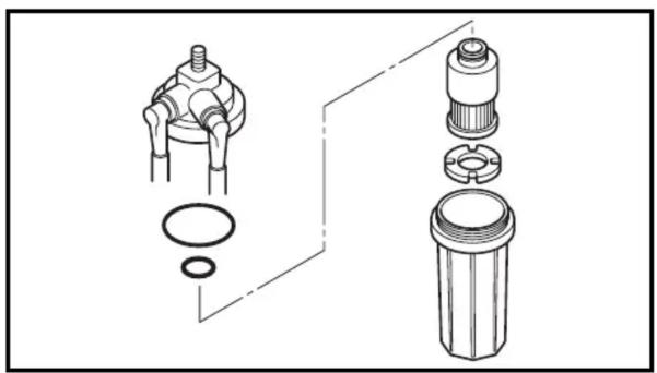
natural_image
Technical diagram showing exploded view of a mechanical assembly with no visible text or symbols
2. Check:
- Plastic locking tie Loosen → Retighten or replace.
3. Check:
- Low-pressure fuel line Cracks/damage/leaks → Replace. Refer to “LOW-PRESSURE FUEL LINE” on page 4-26.
CHECKING THE FUEL FILTER
Check:
- Fuel filter element
- Fuel filter cup
Clogs/cracks/leaks → Replace.
Foreign matter → Clean.
Refer to "FUEL FILTER" on page 4-29.
MEASURING THE FUEL PRESSURE (HIGH-PRESSURE FUEL LINE)
Measure:
- Fuel pressure (high-pressure fuel line) Out of specification → Check the high-pressure fuel line.

Fuel pressure
(high-pressure fuel line)
300 kPa (3.0 kg/cm², 44.1 psi)
Measuring steps
(1) Install the fuel pressure gauge onto the pressure check valve.

Fuel pressure gauge ..... ①
YB-06766 / 90890-06786
(2) Turn the main switch to on, and then measure the fuel pressure.
INSP ADJ

2. Vérifier:

CONTROL SYSTEM CHECKING AND ADJUSTING THE THROTTLE BODY PICKUP TIMING
1. Check:
- Throttle body pickup timing Incorrect → Adjust.
Checking steps
(1) Turn the throttle control lever to the full retard position.
(2) Check that the mark ⓐ on the throttle cam aligns with the center of the throttle roller ① as shown.
2. Adjust:
- Throttle body pickup timing
Adjustment steps
(1) Loosen the nut ①.
(2) Remove the throttle joint link rod ②.
(3) Move the throttle control lever ③ until it contacts the fully-closed stopper ④.
NOTE: \_\_\_\_
Make sure the throttle is fully-closed.
(4) Align the fully-closed mark ⓐ on the throttle control lever ③ with the center of the throttle roller ⑤ as shown.
(5) Adjust the length of the throttle joint link rod until ⓑ is 0.5 mm.
(6) Tighten the nut and install the throttle joint link rod onto the throttle control lever.
(7) Move the throttle control lever to check that the throttle valve opens and closes smoothly. Also, make sure the throttle roller aligns with the fully-open position © on the accelerator cam.
(8) Set the throttle to the fully-closed position and check that the fully-closed mark ⓐ aligns with the center of the throttle roller.
SYSTEME DE
COMMANDE
VERIFICATION ET REGLAGE DU POUVOIR D'ACCELERATION DU CORPS D'ACCELERATEUR
1. Vérifier:
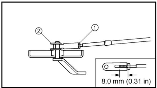
ADJUSTING THE SHIFT CABLE
1. Check:
- Shift operation Incorrect → Adjust.
2. Adjust:
- Shift cable joint position
Adjustment steps
(1) Align the mark ⓐ on the bushing with the mark ⓑ on the bracket Ⓒ.
(2) Loosen the locknut ① and remove the clip ②.
(3) Remove shift cable joint ③ from the set pin.
(4) Position the remote control lever in the neutral position.
(5) Adjust the position of the shift cable joint until it aligns with the set pin.

WARNING
The shift cable joint must be screwed in at least 8 mm (0.31 in).
(6) Install the shift cable joint onto the set pin.
(7) Install the clip and tighten the locknut.
(8) Move the remote control lever to the forward, neutral, and reverse positions and make sure it shifts smoothly and correctly. If the shifting operation is unsmooth or incorrect, repeat the above procedure.
3. Check:
- Shift operation Unsmooth operation → Repair.

ADJUSTING THE THROTTLE CABLE
1. Check:
- Fully closed position Incorrect → Adjust.
Checking steps
(1) Fully close the throttle.
(2) Check that the throttle control lever ① touches the fully-closed stopper ②.
2. Adjust:
- Throttle cable joint position
Adjustment steps
(1) Contact the throttle control lever ① with the fully-closed stopper ②.
(2) Loosen the locknut ③ and remove the clip ④.
(3) Remove throttle cable joint ⑤ from the set pin ⓐ.
(4) Position the remote control lever in the neutral position.
(5) Adjust the position of the throttle cable joint until it aligns with the set pin.
WARNING
The throttle cable joint must be screwed in at least 8 mm (0.31 in).
(6) Install the throttle cable joint onto the set pin.
(7) Install the clip and tighten the locknut.
(8) Open and close the throttle (at the remote control) several times and make sure the throttle valves open and close smoothly and correctly. If the throttle operation is unsmooth or incorrect, repeat the above procedure.
Out of specification → Adjust.

Throttle position sensor output voltage (pink (P) – black (B))
$$ 0. 7 3 2 \pm 0. 0 1 4 \mathrm{V} $$
NOTE:
- Be sure to adjust the throttle valve's opening before measuring the throttle position sensor output voltage.
- When measuring the throttle position sensor output voltage, set the digital tester to the manual range.


Measuring steps
(1) Remove the intake silencer. Refer to "INTAKE ASSEMBLY" on page 4-3.
(2) Disconnect the throttle joint link rod ① at the throttle body.
(3) Check the throttle valve.
(4) Connect the test harness (3-pin) as shown.

Test harness (3-pin) 90890-06793
(5) Connect the digital tester probes to the test harness (3-pin) as shown.
(6) Turn the engine start switch on.
(7) Measure the output voltage.
(8) Install the intake silencer.
(9) Start the engine and measure the output voltage again.
INSP ADJ

2. Adjust:
- Throttle position sensor
Adjustment steps
(1) Loosen the screws ②.
(2) Adjust the position of the throttle position sensor until the specified output voltage is obtained.

Throttle position sensor output voltage (pink (P) – black (B)) 0.732 ± 0.014 V
General adjusting tool Torx T-20 (with a concave in the center)
(3) Tighten the screws.
(4) Connect the throttle joint link rod ①.
SYNCHRONIZING THE THROTTLE VALVES
CAUTION:
Do not adjust the throttle valve when it is operating properly. Excess adjustment may cause poor engine performance.

Adjustment steps
(1) Remove all of the blind plugs ①.
(2) Connect the adaptors ② and vacuum gauge ③ to the intake manifold assembly as shown.

Vacuum gauge set YU-08030 / 90890-03094
(3) Start the engine and allow it to warm up for several minutes.
(4) Connect the tachometer to the spark plug lead of cylinder #1.

Tachometer YU-08036-A / 90890-06760

Engine idling speed 750 ± 50 r/min
INSP ADJ

2. Régler:
(5) Check the vacuum pressure of all cylinders.
(6) Turn the synchronizing screw ④ so the vacuum pressure of cylinder #3 or #4 is within 30 mmHg (40 mbar, 1.18 inHg) based of the vacuum pressure of cylinder #1 or #2.
Tighten Vacuum pressure increases.
Loosen Vacuum pressure decreases.
General adjusting tool
Torx T-25 (with a concave in the center)
Example 1:
Check results:
Cylinder #1
360 mmHg
(480 mbar,
14.2 inHg)
Cylinder #2 350 mmHg
(467 mbar,
13.8 inHg)
Cylinder #3 310 mmHg
(413 mbar,
12.2 inHg)
Cylinder #4
300 mmHg
(400 mbar,
11.8 inHg)
Adjust the difference of the vacuum pressure between cylinders #1 and #4 within 30 mmHg (40 mbar, 1.18 inHg).
Example 2:
Check results:
Cylinder #1 360 mmHg
(480 mbar,
14.2 inHg)
Cylinder #2
350 mmHg
(467 mbar,
13.8 inHg)
Cylinder #3 390 mmHg
(520 mbar,
15.4 inHg)
Cylinder #4
400 mmHg
(533 mbar,
15.8 inHg)
Adjust the difference of the vacuum pressure between cylinders #2 and #4 within 30 mmHg (40 mbar, 1.18 inHg).
INSP ADJ


ADJUSTING THE THROTTLE POSITION SENSOR (WHEN DISASSEMBLING OR REPLACING THE THROTTLE BODY)
Adjusting steps
(1) Install the intake assembly with the intake silencer removed.
(2) Disconnect the throttle position sensor coupler.
(3) Install the test harness to the throttle position sensor coupler.

Test harness 90890-06793
(4) Connect the digital circuit tester.

Digital tester J-39299 / 90890-06752
(5) Turn the main switch to on.
(6) Loosen the synchronizing screw and fully open the lower side throttle valve (#3, 4).
(7) Loosen the idling screw ① and fully close the upper side throttle valve (#1, 2).
(8) Adjust the position of the throttle position sensor until the output voltage is 0.7 ± 0.01 V and operate the throttle valve several times.
(9) Record the value.
(10) Slowly tighten the synchronizing screw ② until the recorded value is changed.
(11) Slowly tighten the idling screw until 0.032 ± 0.004 V increase over the recorded value.
(12) Operate the throttle valve several times.
(13) Install the throttle roller ⓓ as the mark Ⓔ aligns with center of the throttle roller and check that the output voltage is not change.
(14) Install the intake silencer.
(15) Start the engine.
(16) If the output voltage of the throttle position sensor is not within 0.732 ± 0.014 V, adjust the throttle position sensor.
(17) Check that the throttle valve is synchronized.
REGLAGE DU CAPTEUR DE POSITION D'ACCELERATEUR (LORS DU DEMONTAGE OU DU REMPLACEMENT DU CORPS D'ACCELERATEUR)
natural_image
Line drawing of a car's side panel with a black arrow pointing to the handle (no text or symbols)COOLING SYSTEM CHECKING THE COOLING WATER DISCHARGE
Check:
- Cooling water discharge No discharge → Clean and check the cooling water passage.
Checking steps
(1) Place the lower unit in water.
(2) Start the engine.
(3) Check that water flows from the cooling water outlet.

POWER UNIT CHECKING THE ENGINE OIL LEVEL
Check:
- Engine oil level Above ⓐ → Check for fuel in the engine oil. Below ⓑ → Add engine oil so that the level is between ⓐ and ⓑ.

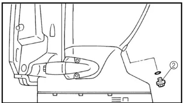
REPLACING THE ENGINE OIL/OIL FILTER
-
Remove:
-
Oil filler cap ①
-
Drain plug ②
-
Remove:
- Oil filter ③

Oil filter wrench YU-38411 / 90890-01426
- Install:
- Drain plug ②

Drain plug 28 Nm (2.8 m · kgf, 20 ft · lb)
natural_image
Technical line drawing of a mechanical component with labeled parts (no text or symbols present)SYSTEME DE
REFROIDISSEMENT
VERIFICATION DE LA VIDANGE
DE L'EAU DE
REFROIDISSEMENT
Vérifier:

natural_image
Illustration of a hand pouring liquid into a mechanical device (no text or symbols visible)4. Install:
- Oil filter ③

Oil filter 18 Nm (1.8 m · kgf, 13.3 ft · lb)
NOTE: \_\_\_\_
Lubricate the rubber seal with engine oil before installation.
5. Add:
- Engine oil

Recommended engine oil
4 stroke motor oil
API: SE, SF, SG or SH
SAE: 10W-30, 10W-40
Oil quantity
with oil filter
4,700 cm ^3
(159 US oz, 165 Imp oz)
without oil filter
4,500 cm ^3
(152 US oz, 158 Imp oz)
6. Install:
- Oil filler cap
7. Check:
- Engine oil level
Refer to "CHECKING THE ENGINE OIL LEVEL" on page 3-11.
NOTE: \_\_\_\_
- Run the engine for several minutes and then check the engine oil level.
- If the engine oil is still not within the proper level, add/drain as needed.

natural_image
Technical line drawing of a mechanical belt drive component (no text or symbols)CHECKING THE TIMING BELT
Check:
- Timing belt
Wear/damage → Replace.
- Installer:
- Filtre à huile ③

Filtre à huile
18 Nm
(1,8 m • kgf, 13,3 ft • lb)
N.B.:
API: SE, SF, SG o SH
SAE: 10W-30, 10W-40
Cantidad de aceite

ADJUSTING THE VALVE CLEARANCE
NOTE:
Valve clearance adjustment should be made on a cold engine, at room temperature.
1. Remove:
- Flywheel magnet cover
- Spark plug cap cover ①
2. Disconnect:
- Spark plug leads ②
- Fuel hoses ③
- Ventilation hose
- Vacuum hose
3. Loosen:
- Timing belt tensioner
4. Remove:
- Timing belt
- Driven sprockets
- Cylinder head cover
- Spark plugs
5. Install:
- Driven sprockets
- Timing belt
6. Tighten:
- Timing belt tensioner
7. Measure:
- Intake valve clearance ⓐ
- Exhaust valve clearance ⓑ

Valve clearance
Intake
0.20 ± 0.03 mm
(0.008 ± 0.001 in)
Exhaust
0.34 ± 0.03 mm
(0.013 ± 0.001 in)
NOTE:
If any valve clearance is out of specification, record its measurement.
REGLAGE DU JEU DE SOUPAPE
N.B.:
Measurement steps
(1) Turn the flywheel magneto clockwise until cylinder #1's piston is at TDC.
(2) Measure the intake valve clearance for cylinders #1 and #2.
(3) Measure the exhaust valve clearance for cylinders #1 and #3.
(4) Turn the flywheel magneto 360^ clockwise.
(5) Measure the intake valve clearance for cylinders #3 and #4.
(6) Measure the exhaust valve clearance for cylinders #2 and #4.
8. Loosen:
- Timing belt tensioner
9. Remove:
- Timing belt
- Driven sprockets
- Camshaft caps
- Camshafts
Refer to "POWER UNIT" on page 5-4.
10. Adjust:
- Valve clearance
NOTE:
- Do not mix the valve train parts (i.e., valve pads, camshaft caps, camshafts). Keep them organized in their proper groups (e.g., cylinder #1 parts kept together).
- Install the removed parts in their original positions. If valve train parts are installed in the wrong position, proper valve adjustments are impossible.
INSP ADJ

Etapes de la mesure
(1) Insert a thin screwdriver into the notch in the valve lifter.
(2) Carefully pry up the valve pad and remove it.
(3) Measure the thickness removed valve pad with a micrometer.
(4) Select a proper replacement valve pad by calculating its thickness with the following formula.
Proper valve pad thickness = Removed valve pad thickness + Measured valve clearance - Specified valve clearance
(5) Install the proper valve pad into the valve lifter.
NOTE:
- Measure the thickness of the new valve pad with a micrometer because the thickness number is not indicated on the pad.
- Lubricate the valve pad with molybdenum disulfide grease.
- Perform the above procedure for all valves whose clearances are out of specification.
11. Install:
- Camshafts
- Camshaft caps
- Driven sprockets
- Timing belt
12. Tighten:
- Timing belt tensioner
Refer to "POWER UNIT" on page 5-4.
13. Recheck:
- Valve clearance
NOTE:
If any valve clearance is still out of specification, repeat all of the valve clearance adjustment steps until the specified clearance is obtained.
INSP ADJ

Etapes du réglage
- Timing belt tensioner
-
Remove:
-
Driven sprockets
-
Timing belt
-
Tighten:
- Timing belt tensioner
-
Install:
-
Cylinder head cover
- Driven sprockets
- Timing belt
-
Spark plugs
-
Connect:
-
Vacuum hose
- Ventilation hose
- Fuel hoses
-
Spark plug leads
-
Install:
-
Spark plug cap cover
• Flywheel magneto cover
POWER TRIM AND TILT SYSTEM CHECKING THE POWER TRIM AND TILT FLUID LEVEL
Check:
- Power trim and tilt fluid level Level is low → Add power trim and tilt fluid to the proper level.

Recommended power trim and tilt fluid ATF Dexron II

natural_image
Mechanical assembly diagram showing a valve mechanism with no visible text or symbolsWARNING
When removing the power trim and tilt reservoir cap, the power trim and tilt fluid may spurt out due to internal pressure. Therefore, fully tilt up the outboard (the tilt ram assembly fully extended) and then slowly remove the power trim and tilt reservoir cap.
INSP ADJ

MOTEUR/SYSTEME D'ASSIETTE ET D'INCLINAISON ASSISTEES
MOTORBLOCK/SERVO-TRIMM UND KIPPSYSTEM

Checking steps
(1) Tilt the outboard all the way up and lock it with the tilt stop levers ①.
WARNING
After tilting up the outboard, be sure to support it with the tilt stop levers.
Otherwise, the outboard could suddenly lower if the power trim and tilt unit should lose fluid pressure.
(2) Remove the reservoir cap ② and check the fluid level.
NOTE:
The fluid level should be directly below the check hole as shown.
(3) Add power trim and tilt fluid if needed, and then install the reservoir cap.

Reservoir cap 8 Nm (0.8 m · kgf, 5.8 ft · lb)
ADJUSTING THE TRIM SENSOR CAM
1. Measure:
- Trim sensor setting resistance Out of specification → Adjust.

Trim sensor setting resistance Pink (P) – Black (B) 80 ± 12 Ω at 20 °C (68 °F)

Measuring steps
(1) Fully tilt the outboard down.
(2) Measure the trim sensor resistance.
INSP ADJ

SYSTEME D'ASSIETTE ET D'INCLINAISON ASSISTEES
SERVO-TRIMM UND KIPPSYSTEM
2. Adjust:
- Trim sensor cam position
Adjusting steps
(1) Fully tilt the outboard to full trim-in position.
(2) Loosen the screw ①.
(3) Adjust the position of the trim sensor cam ② until the specified resistance is obtained.

Trim sensor resistance
Pink (P) - Black (B)
80 ± 12 Ω at 20 °C (68 °F)
(4) Tighten the screw.

Trim sensor cam screw
2 Nm (0.2 m · kgf, 1.4 ft · lb)
LOWER UNIT CHECKING THE GEAR OIL LEVEL
Check:
- Gear oil level
Level is low → Add gear oil to the proper level.

CHANGING AND CHECKING THE GEAR OIL
- Check:
- Gear oil
Milky oil → Replace the oil seal.
Slag oil → Check the gears, bearings, and clutch dog.
Checking steps
(1) Tilt up the outboard slightly.
(2) Place a container under the gear oil drain screw ①.
(3) Remove the gear oil drain screw and gear oil level check screw ②.
INSP ADJ

2. Régler:
- Gear oil (with the specified amount of the recommend gear oil)

Recommended gear oil GEAR CASE LUBE (USA) or Hypoid gear oil, SAE 90
Total amount Regular rotation models 760 cm ^3 (25.7 US oz, 26.8 Imp oz) Counter rotation models 715 cm ^3 (24.2 US oz, 25.2 Imp oz)
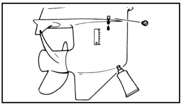
natural_image
Line drawing of a mechanical device with a spring scale and hanging weights (no text or symbols)Filling steps
(1) Place the outboard in an upright position.
(2) Insert the gear oil tube into the drain hole and slowly fill the gear oil until oil flows out of the check hole and no air bubbles are visible.
(3) Install the gear oil level check screw and then quickly install the gear oil drain screw.

Gear oil level check screw 7 Nm (0.7 m · kgf, 5.1 ft · lb) Gear oil drain screw
7 Nm (0.7 m · kgf, 5.1 ft · lb)
INSP ADJ

2. Remplir:
CHECKING THE LOWER UNIT (FOR AIR LEAKS)
Check:
- Lower unit holding pressure Pressure drops → Check the seals and components.
Lower unit holding pressure 100 kPa (1.0 kg/cm ^2 , 14.2 psi)

natural_image
Line drawing of a hand holding a pressure gauge connected to a device inside a container (no text or symbols)Checking steps
CAUTION:
Do not overpressurize the lower unit. Excessive pressure may damage the oil seals.
(1) Remove the gear oil level check screw.
(2) Install the pressure tester into the check hole.

Pressure tester YB-35956 / 90890-06762
(3) Apply the specified pressure.
NOTE:
The lower unit should hold the specified pressure for 10 seconds.

GENERAL
CHECKING THE ANODES
Check:
- Anodes ①
- Trim tab ②
Scales → Clean.
Grease/oil → Clean.
Excessive wear → Replace.
CAUTION:
Do not oil, grease or paint the anode, or it will not operate properly.
INSP ADJ

VERIFICATION DU BLOC DE PROPULSION
(POUR LES FUITES D'AIR)
Vérifier:
Battery electrolytic fluid is dangerous; it contains sulfuric acid and therefore is poisonous and highly caustic.
Always follow these preventive measures:
- Avoid bodily contact with electrolytic fluid as it can cause severe burns or permanent eye injury.
- Wear protective eye gear when handling or working near batteries.
Antidote (EXTERNAL):
- SKIN - Flush with water.
- EYES - Flush with water for 15 minutes and get immediate medical attention.
Antidote (INTERNAL):
- Drink large quantities of water or milk followed by milk of magnesia, beaten egg, or vegetable oil. Get immediate medical attention.
Batteries also generate explosive hydrogen gas; therefore, you should always follow these preventive measures:
- Charge batteries in a well-ventilated area.
- Keep batteries away from fire, sparks, or open flames (e.g., welding equipment, lighted cigarettes, etc.).
- DO NOT SMOKE when charging or handling batteries.
KEEP BATTERIES AND ELECTROLYTIC FLUID OUT OF REACH OF CHILDREN.
NOTE:
- Batteries vary among manufacturers. Therefore, the following procedures may not always apply. Consult your battery manufacturer's instructions.
- First, disconnect the negative lead, then the positive lead.
VERIFICATION DE LA BATTERIE
AVERTISSEMENT
- Electrolyte level
Below the minimum level mark → Add distilled water to the proper level.
• Electrolyte specific gravity
Less than specification → Recharge the battery.

Electrolyte specific gravity 1.280 at 20°C (68°F)

natural_image
Technical line drawing of a mechanical component with threaded end and labeled section (a), no readable text or symbols present.CHECKING THE SPARK PLUGS
1. Check:
- Electrodes ①
Cracks/excessive wear → Replace. - Insulator color ②
Distinctly different color → Check the engine condition.
2. Clean:
- Spark plug (with a spark plug cleaner or wire brush.)
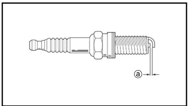
3. Measure:
- Spark plug gap @ Out of specification → Regap.

Spark plug gap 1.0 - 1.1 mm (0.039 - 0.043 in)
INSP ADJ

GENERALITES
ALLGEMEINES
GENERAL
Vérifier:
4. Tighten:
- Spark plug

Spark plug 25 Nm (2.5 m · kgf, 18 ft · lb)
NOTE:
- Before installing the spark plug, clean the gasket surface and spark plug surface. Also, it is suggested to apply a thin film of anti-seize compound to the spark plug threads to prevent thread seizure.
- If a torque wrench is not available, a good estimate of the correct tightening torque is to finger tighten ① the spark plug and then tighten it another 1/4 to 1/2 of a turn ⑥.
COMPRESSION PRESSURE MEASUREMENT
CAUTION:
Before removing a spark plug, use compressed air to blow away dirt accumulated in the spark plug well to prevent it from falling into the cylinder that is being tested.
1. Check:
- Valve clearance Out of specification → Adjust. Refer to “ADJUSTING THE VALVE CLEARANCE” on page 3-13.
2. Warm-up:
- Engine
3. Remove:
- Spark plug(-s)
4. Install:
- Compression gauge ① (into the spark plug hole)
NOTE:
Use a compression gauge that is used for automobiles.
INSP ADJ

- Serrer:
• Bougie

Bougie
25 Nm
(2,5 m • kgf, 18 ft • lb)
N.B.:
- Compression pressure Below minimum compression pressure → Inspect valve clearance, valve face, valve seat, piston rings, cylinder sleeve, piston, cylinder head gasket and cylinder head.

Compression pressure Minimum 950 kPa (9.5 kg/cm², 135 psi)
Measurement steps
(1) Remove the lock plate from the engine stop lanyard switch on the remote control box.
(2) With the throttle wide open, crank the engine setting the main switch in the START position until the reading on the compression gauge stabilizes.
6. Remove:
- Compression gauge
7. Install:
- Spark plug(-s)
OIL PRESSURE MEASUREMENT
1. Warm-up:
- Engine
2. Remove:
- Oil pressure switch
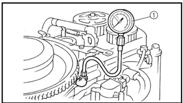
3. Install:
- Oil pressure gauge ① (into the oil pressure switch hole)
NOTE:
Use a pressure gauge with the range of 0 to 10 kg/cm ^2 and an adopter with a PT 1/4 thread.
INSP ADJ

5. Mesurer:
- Pression de compression
- Oil pressure Out of specification → Check the oil pump, oil suction pipe and oil strainer.

Oil pressure
At idling (55 °C (131 °F))
350 kPa (3.5 kg/cm², 49.8 psi)
or higher
5. Remove:
- Oil pressure gauge
6. Install:
- Oil pressure switch

natural_image
Technical diagram showing mechanical components with arrows indicating assembly or movement (no text or labels present)
natural_image
Diagram of a mechanical device with arrows indicating movement or force direction (no text or symbols present)
natural_image
Line drawing of a car interior showing a seatbelt switch and a hand inserting a valve (no text or symbols)LUBRICATION POINTS
1. Apply:
• Water resistant grease
INSP ADJ

GENERALITES
ALLGEMEINES
GENERAL
4. Mesurer:
- Pression d'huile
natural_image
Mechanical assembly diagram showing a lever mechanism with arrows indicating direction (no text or symbols present)
natural_image
Mechanical component diagram showing a shaft inserted into a housing with two arrows indicating direction (no text or symbols)
natural_image
Technical line drawing of a mechanical device with hoses and connectors, no visible text or symbols
natural_image
Mechanical assembly diagram showing a valve mechanism with black arrows indicating force or movement (no text or labels)2. Apply:
• Corrosion resistant grease
- Appliquer:
- Graisse anti-corrosion
- Auftragen:
REMOVING/INSTALLING THE FUEL HOSES.... 4-14
VAPOR SEPARATOR.... 4-15
REMOVING/INSTALLING THE VAPOR SEPARATOR 4-15
DISASSEMBLING/ASSEMBLING THE VAPOR SEPARATOR .... 4-16
HIGH-PRESSURE FUEL PUMP 4-17
DISASSEMBLING/ASSEMBLING THE HIGH-PRESSURE FUEL PUMP 4-17
PRESSURE REGULATOR.... 4-18
REMOVING/INSTALLING THE PRESSURE REGULATOR 4-18
CHAPITRE 4
SYSTEME
D'ALIMENTATION
SILENCIEUX D'ADMISSION......4-1
DEPOSE/INSTALLATION DU SILENCIEUX D'ADMISSION.....4-1
ENSEMBLE D'ADMISSION .....4-3
DEPOSE/INSTALLATION DE L'ENSEMBLE D'ADMISSION .....4-3
CORPS D'ACCELERATEUR......4-5
DEPOSE/INSTALLATION DU CORPS D'ACCELERATEUR .....4-5
UNITE DE COMMANDE....4-6
DEPOSE/INSTALLATION DE L'UNITE DE COMMANDE......4-6
CANALISATION DE CARBURANT
HAUTE PRESSION ......4-8
DEPOSE/INSTALLATION DE LA CANALISATION DE CARBURANT HAUTE PRESSION .... 4-8
REDUCTION DE LA PRESSION DE CARBURANT (CANALISATION DE CARBURANT HAUTE PRESSION)....4-10 VERIFICATION DU REGULATEUR DE PRESSION..4-11
INJECTEURS DE CARBURANT ..4-12
DEPOSE/INSTALLATION DES INJECTEURS DE CARBURANT..4-12 DEMONTAGE/MONTAGE DES INJECTEURS DE CARBURANT..4-13
FLEXIBLES DE CARBURANT .....4-14
DEPOSE/INSTALLATION DES FLEXIBLES DE CARBURANT ..4-14
SEPARATEUR DE VAPEUR......4-15
DEPOSE/INSTALLATION DU SEPARATEUR DE VAPEUR .....4-15 DEMONTAGE/MONTAGE DU SEPARATEUR DE VAPEUR .....4-16
POMPE DE CARBURANT
HAUTE PRESSION ....4-17 DEMONTAGE/MONTAGE DE LA POMPE DE CARBURANT HAUTE PRESSION .... 4-17
REGULATEUR DE PRESSION .....4-18
DEPOSE/INSTALLATION DU REGULATEUR DE PRESSION...4-18
KAPITEL 4 KRAFTSTOFFANLAGE
EINLASS-SCHALLDÄMPFER ...... 4-1
AUSBAU/EINBAU DES EINLASS-SCHALLDÄMPFERS .... 4-1
EINLASS-BAUTEIL 4-3
AUSBAU/EINBAU DES EINLASS-BAUTEILS.... 4-3
DROSSELVENTILGEHÄUSE ...... 4-5
AUSBAU/EINBAU DES DROSSELVENTILGEHÄUSES .. 4-5
| Order | Job/Part Q'ty Remarks | ||
| Flywheel cover Refer to “FLYWHEEL MAGNET | |||
| 1 Plastic locking tie 1 | ASSEMBLY” on page 5-1. | ||
| 2 Hose 1 (cylinder head cover-to-intake silencer) | Not reusable | ||
| 3 Hose 1 (vapor separator-to-intake silencer) | |||
| 4 Intake air temperature sensor coupler | 1 | ||
| 5 Intake air temperature sensor 1 | |||
| 6 Bolt 2 | |||
| Continued on next page. | |||
SILENCIEUX D'ADMISSION
DEPOSE/INSTALLATION DU SILENCIEUX D'ADMISSION
| Order | Job/Part Q'ty Remarks | ||
| Intake silencer Refer to “INTAKE SILENCER” on page 4-1. | |||
| 1 Throttle joint link rod 1 | |||
| 2 Throttle position sensor coupler 1 | |||
| 3 Idle speed control valve coupler 1 | |||
| 4 Atmospheric pressure sensor coupler | 1 | ||
| 5 Fuel injector coupler 4 | |||
| 6 High-pressure fuel pump coupler 1 | |||
| 7 Bolt 4 | |||
| 8 Bolt 4 | |||
| Continued on next page. | |||
ENSEMBLE D'ADMISSION
DEPOSE/INSTALLATION DE L'ENSEMBLE D'ADMISSION
| Order | Job/Part Q'ty Remarks | ||
| Intake assembly Refer to “INTAKE ASSEMBLY” on page 4-3. | |||
| 1 Bolt 4 | |||
| 2 Bracket 2 | |||
| 3 Bolt 6 | |||
| 4 Throttle body #1 1 | |||
| 5 Spring 1 | |||
| 6 Throttle joint link rod 1 | |||
| 7 Throttle body #2 1 | |||
| 8 O-ring 4 2.46 | · 48 mmFor installation, reverse the removal procedure. | ||
CORPS D'ACCELERATEUR
DEPOSE/INSTALLATION DU CORPS D'ACCELERATEUR
| Order | Job/Part Q'ty Remarks | ||
| Intake silencer Refer to “INTAKE SILENCER” on page 4-1. | |||
| 1 Bolt 12 Collar 13 Wave washer 14 Washer 15 Throttle control lever 16 Spring 17 Washer 1 | |||
| Continued on next page. | |||
UNITE DE COMMANDE
DEPOSE/INSTALLATION DE L'UNITE DE COMMANDE
| Order | Job/Part Q'ty Remarks | ||
| Intake assembly Refer to “INTAKE | ASSEMBLY” on page 4-3. | ||
| 1 Bolt 3 | |||
| 2 Washer 3 | |||
| 3 Vapor separator 1 | |||
| 4 Plastic locking tie 2 | Not reusable | ||
| 5 Bolt 2 | |||
| 6 Washer 2 | |||
| 7 Fuel cooler 1 | |||
| 8 Collar 2 | |||
| Continued on next page. |
FUEL

CANALISATION DE CARBURANT HAUTE PRESSION
| Order | Job/Part Q'ty Remarks | ||
| 9 Hose 1 (intake manifold-to-pressure regulator) | |||
| 10 Bolt 2 | |||
| 11 Washer 2 | |||
| 12 Bolt 1 | |||
| 13 Washer 1 | |||
| 14 Fuel rail 1 | |||
| 15 Collar 2 | |||
| 16 Collar 1 | |||
| For installation, reverse the removal procedure. | |||
Always reduce the fuel pressure in the high-pressure fuel line before servicing the line or the vapor separator. If the fuel pressure is not released, pressurized fuel may spray out.
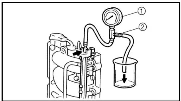
- Reduce:
- Fuel pressure (high-pressure fuel line)
Reducing steps
(1) Install the fuel pressure gauge onto the pressure check valve.

Fuel pressure gauge ....① YB-06766 / 90890-06786
(2) Place the drain hose into a container.
(3) Open the valve ② and release the pressure.
- Drain:
- Fuel
FUEL

CANALISATION DE CARBURANT HAUTE PRESSION
CHECKING THE PRESSURE REGULATOR
Check:
- Pressure regulator
Faulty → Replace the pressure regulator.
Checking steps
(1) Install the fuel pressure gauge onto the pressure check valve.

Fuel pressure gauge ....① YB-06766 / 90890-06786
(2) Main switch to on.
(3) Check the fuel pressure.

Fuel pressure
Approx.
300 kPa (3.0 kg/cm², 44.1 psi)
(4) Start the engine.
(5) Check the fuel pressure.

Fuel pressure
Approx.
250 kPa (2.5 kg/cm², 35.6 psi)
FUEL

CANALISATION DE CARBURANT HAUTE PRESSION
| Order | Job/Part Q'ty Remarks | ||
| High-pressure fuel line Refer to “HIGH-PRESSURE FUEL LINE” | |||
| 1 Bolt 2 | |||
| 2 Washer 2 | |||
| 3 Fuel cooler 1 | |||
| 4 Collar 2 | |||
| 5 Fuel injector coupler 4 | |||
| 6 Fuel injector 4 | |||
| For installation, reverse the removal procedure. | |||
INJECTEURS DE CARBURANT
DEPOSE/INSTALLATION DES INJECTEURS DE CARBURANT
| Order | Job/Part Q'ty Remarks | ||
| 1 Rubber seal 12 Rubber damper 13 O-ring 1 2.2 | · 7.8 mmFor assembly, reverse the disassembly procedure. | ||
DEMONTAGE/MONTAGE DES INJECTEURS DE CARBURANT
| Order | Job/Part Q'ty Remarks | ||
| High-pressure fuel line Refer to “HIGH-PRESSURE FUEL LINE” | |||
| 1 Hose clamp 2 | Not reusable | ||
| 2 Hose clamp 4 | |||
| 3 Fuel hose 1 (vapor separator-to-fuel rail) | |||
| 4 Fuel hose 1 (pressure regulator-to-fuel cooler) | |||
| 5 Fuel hose 1 (fuel cooler-to-vapor separator) | |||
| For installation, reverse the removal procedure. | |||
FLEXIBLES DE CARBURANT
DEPOSE/INSTALLATION DES FLEXIBLES DE CARBURANT
| Order | Job/Part Q'ty Remarks | ||
| Fuel hoses Refer to “FUEL HOSES” on page 4-14. | |||
| 1 Bolt 32 Washer 33 Hose 1 (vapor separator-to-intake silencer)4 Vapor separator 1 | |||
SEPARATEUR DE VAPEUR
DEPOSE/INSTALLATION DU SEPARATEUR DE VAPEUR
| Order | Job/Part Q'ty Remarks | ||
| 1 | Drain screw 1 | ||
| 2 | Gasket 1 | ||
| 3 | Screw 7 | ||
| 4 | O-ring 1 | ||
| 5 | Float chamber 1 | ||
| 6 | Holder 1 | ||
| 7 | High-pressure fuel pump filter 1 | ||
| 8 | Vapor separator body 1 | ||
| For assembly, reverse the disassembly procedure. |
DEMONTAGE/MONTAGE DU SEPARATEUR DE VAPEUR
| Order | Job/Part Q'ty Remarks | ||
| 1 | Float pin 1 | ||
| 2 | Float 1 | ||
| 3 | Needle valve 1 | ||
| 4 | Screw 1 | ||
| 5 | Retainer 1 | ||
| 6 | Collar 1 | ||
| 7 | O-ring 1 1.35 | · 7 mm | |
| 8 | High-pressure fuel pump 1 | ||
| 9 | Grommet 1 | ||
| 10 | High-pressure fuel pump connector | 1 | For assembly, reverse the disassembly procedure. |
POMPE DE CARBURANT HAUTE PRESSION
DEMONTAGE/MONTAGE DE LA POMPE DE CARBURANT HAUTE PRESSION
| Order | Job/Part Q'ty Remarks | ||
| Fuel rail Refer to “HIGH-PRESSURE FUEL LINE”on page 4-8.Before performing the following procedure, reduce the fuel pressure (high-pressure fuel line) | |||
| 1 Hose clamp 12 Hose 1 (fuel cooler-to-pressure regulator)3 Hose 1 (intake manifold-to-pressure regulator)4 Screw 25 Pressure regulator 16 O-ring 1 1.8 · 8 mm | |||
REGULATEUR DE PRESSION
DEPOSE/INSTALLATION DU REGULATEUR DE PRESSION
| Order | Job/Part Q'ty Remarks | ||
| Intake assembly Refer to “INTAKE | ASSEMBLY” on page 4-3. | ||
| 1 Hose 1 (idle speed control assembly-to-intake | |||
| 2 Bolt 1 | |||
| 3 Washer 1 | |||
| 4 Bolt 2 | |||
| 5 Washer 2 | |||
| 6 Hose clamp 4 | |||
| Continued on next page. | |||
ENSEMBLE DE COMMANDE DU REGIME DE RALENTI
DEPOSE/INSTALLATION DE L'ENSEMBLE DE COMMANDE DU REGIME DE RALENTI
| Order | Job/Part Q'ty Remarks | ||
| 1 | Screw 2 | ||
| 2 | Pressure sensor 1 | ||
| 3 | O-ring 1 1.9 · 14.8 mm | ||
| 4 | Screw 3 | ||
| 5 | Idle speed control 1 | ||
| 6 | O-ring 1 2 · 29 mm | ||
| 7 | Filter 1 | ||
| 8 | Idle speed control body 1 | For assembly, reverse the disassembly procedure. |
DEMONTAGE/MONTAGE DE L'ENSEMBLE DE COMMANDE DU REGIME DE RALENTI
| Order | Job/Part Q'ty Remarks | ||
| Fuel injectors Refer to “FUEL INJECTORS” on page 4-12.Fuel hoses Refer to “FUEL HOSES” on page 4-14.Pressure regulator Refer to “PRESSURE REGULATOR” on page 4-18. | |||
| 1 Cap 12 Screw 23 Fuel rail joint 14 O-ring 1 2.4 · 12 mm5 Fuel rail 1 | For assembly, reverse the disassembly procedure. | ||
RAIL DE CARBURANT
DEMONTAGE/MONTAGE DU RAIL DE CARBURANT
CARRIL DE COMBUSTIBLE
DESMONTAJE/MONTAJE DEL CARRIL DE COMBUSTIBLE
| Order | Job/Part Q'ty Remarks | ||
| Throttle body Refer to “THROTTLE BODY” on page 4-5.High-pressure fuel line Refer to “HIGH-PRESSURE FUEL LINE”on page 4-8.Idle speed control assembly Refer to “IDLE SPEED CONTROLSSEMBLY” on page 4-19. | |||
| 1 Hose 1 (pressure regulator-to-intake manifold-to-idle speed control assembly) | |||
| 2 Collar 63 Grommet 34 Rubber seal 45 Intake manifold 1 | |||
| For assembly, reverse the disassembly procedure. | |||
TUBULURE D'ADMISSION
DEMONTAGE/MONTAGE DE LA TUBULURE D'ADMISSION
| Order | Job/Part Q'ty Remarks | ||
| 1 Throttle position sensor connector2 Screw 23 Throttle position sensor 1 | 1 | For installation, reverse the removal procedure. | |
FUEL

CAPTEUR DE POSITION D'ACCELERATEUR
DROSSELVENTIL-POSITIONSSENSOR
During installation, make sure the throttle position sensor is properly adjusted.
Install:
- Throttle position sensor Refer to "ADJUSTING THE THROTTLE POSITION SENSOR" on page 3-7.
FUEL

INSTALLATION DU CAPTEUR DE POSITION D'ACCELERATEUR
N.B.:
| Order | Job/Part Q'ty Remarks | ||
| 1 | Bolt 2 | ||
| 2 | Grommet retaining plate 1 | ||
| 3 | Bolt 1 | ||
| 4 | Plate 1 | ||
| 5 | Bolt 1 | ||
| 6 | Clamp plate 1 | ||
| 7 | Bolt 1 | ||
| 8 | Screw 5 | ||
| 9 | Plug cover 1 | ||
| Continued on next page. |
FUEL

CANALISATION DE CARBURANT BASSE PRESSION
| Order | Job/Part Q'ty Remarks | ||
| 10 | Bolt 2 | ||
| 11 | O-ring 1 3.1 · 29.4 mm | ||
| 12 | Plastic locking tie 1 | Not reusable | |
| 13 | Hose 1 | ||
| 14 | Plastic locking tie 1 | Not reusable | |
| 15 | Fuel hose joint 1 | ||
| 16 | Low-pressure fuel line 1 | ||
| For installation, reverse the removal procedure. |
| Order | Job/Part Q'ty Remarks | ||
| 1 Plastic locking tie 42 Fuel hose 1 (hose joint-to-fuel filter)3 Fuel filter 14 Fuel hose 1 (fuel pump-to-fuel filter)5 Fuel pump 1 | Not reusableFor assembly, reverse the disassembly procedure. | ||
DEMONTAGE/MONTAGE DE LA CANALISATION BASSE PRESSION
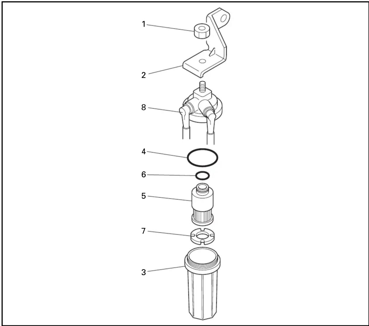
| Order | Job/Part Q'ty Remarks | ||
| 1 Nut 12 Fuel filter bracket 13 Fuel filter cup 14 O-ring 1 2.0 · 32.2 mm5 Fuel filter element 16 O-ring 1 1.5 · 13.5 mm7 Float 18 Fuel filter cap 1 | Not reusableNot reusableFor assembly, reverse the disassembly procedure. | ||
FUEL

FILTRE DE CARBURANT
DEMONTAGE/MONTAGE DU FILTRE DE CARBURANT
| Order | Job/Part Q'ty Remarks | ||
| 1 | Screw 3 | ||
| 2 | Nut 4 | ||
| 3 | Fuel pump cover 1 | ||
| 4 | Gasket 1 |  | |
| 5 | Fuel pump body 1 | ||
| 6 | Pin 1 | ||
| 7 | Plunger 1 | ||
| 8 | Spring 1 | ||
| 9 | Diaphragm 1 | ||
| 10 | Spring 1 | ||
| 11 | Fuel pump cover 1 | ||
| For assembly, reverse the disassembly procedure. |
POMPE DE CARBURANT
DEMONTAGE/MONTAGE DE LA POMPE DE CARBURANT
-
Check:
-
Diaphragm
-
Fuel pump valves Damage → Replace.
-
Check:
-
Fuel pump
Reverse air flow → Replace.

Checking steps
NOTE:
Do not overpressurize the fuel pump. Excessive pressure may cause air to leak out.
(1) Install the Mity vac onto the fuel pump as shown.

Mity vac YB-35956 / 90890-06756
(2) Apply the specified pressure with the Mity vac.

Fuel pump pressure ① 50 kPa (0.5 kg/cm², 7.1 psi) Fuel pump negative pressure ② 30 kPa (0.3 kg/cm², 4.3 psi)
NOTE:
- Make sure no air comes out of the opposite side of the fuel pump.
- To eliminate any gaps between the fuel pump valves and the fuel pump body, and to ensure a better seal, make sure the inside of the fuel pump is wet (i.e., with gas).
FUEL

VERIFICATION DES POMPES DE CARBURANT
1. Vérifier:
- Diaphragme
- Clapets de la pompe de carburant Endommagement → Remplacer.
2. Vérifier:
REMOVING/INSTALLING THE POWER UNIT 5-8
STATOR COIL ASSEMBLY 5-9
REMOVING/INSTALLING THE STATOR COIL ASSEMBLY.... 5-9
TIMING BELT 5-10
REMOVING/INSTALLING THE TIMING BELT 5-10
REMOVING THE DRIVEN SPROCKET 5-12
REMOVING/INSTALLING THE DRIVE SPROCKET.... 5-12
INSTALLING THE DRIVEN SPROCKET.... 5-13
INSTALLING THE TIMING BELT 5-13
IGNITION COILS AND STARTER MOTOR.... 5-14
REMOVING/INSTALLING THE IGNITION COILS AND
STARTER MOTOR.... 5-14
ECM AND JUNCTION BOX ASSEMBLY.... 5-15
REMOVING/INSTALLING THE CDI UNIT AND JUNCTION BOX ASSEMBLY 5-15
DISASSEMBLING/ASSEMBLING THE JUNCTION BOX ASSEMBLY....5-18
CYLINDER HEAD COVER.... 5-20
REMOVING/INSTALLING THE CYLINDER HEAD COVER 5-20
CAMSHAFTS 5-21
REMOVING/INSTALLING THE CAMSHAFTS.... 5-21
CHECKING THE CAMSHAFT.... 5-22
INSTALLING THE CAMSHAFT.... 5-22
CHAPITRE 5 MOTEUR
KAPITEL 5 MOTOR
CAPITULO 5 MOTOR
ENSEMBLE DE VOLANT
MAGNETIQUE ....5-1
DEPOSE/INSTALLATION DE L'ENSEMBLE DE VOLANT MAGNETIQUE....5-1
DEPOSE DE L'ENSEMBLE DE VOLANT MAGNETIQUE ....5-2 INSTALLATION DE L'ENSEMBLE DE VOLANT MAGNETIQUE .... 5-3
MOTEUR....5-4
DECONNECTER/CONNECTER DU CABLE DE COMMANDE....5-4 DECONNECTER/CONNECTER DES FILS....5-6 DEPOSE/INSTALLATION DU MOTEUR....5-8
ENSEMBLE DE LA BOBINE DE
STATOR....5-9 DEPOSE/INSTALLATION DE L'ENSEMBLE DE LA BOBINE DE STATOR....5-9
COURROIE DE SYNCHRONI-
SATION....5-10 DEPOSE/INSTALLATION DE LA COURROIE DE SYNCHRONISATION....5-10 DEPOSE DE LA ROUE DENTEE MENEE....5-12 DEPOSE/INSTALLATION DE LA ROUE DENTEE D'ENTRAINE-MENT....5-12 INSTALLATION DE LA ROUE DENTEE MENEE....5-13 INSTALLATION DE LA COURROIE DE SYNCHRONISATION....5-13
BOBINES D'ALLUMAGE ET
MOTEUR DE DEMARREUR......5-14 DEPOSE/INSTALLATION DES BOBINES D'ALLUMAGE ET DU MOTEUR DE DEMARREUR ......5-14
ECM ET ENSEMBLE DE BOITE
D'ACCOUPLEMENT....5-15 DEPOSE/INSTALLATION DU BLOC CDI ET DE L'ENSEMBLE DE BOITE D'ACCOUPLEMENT .....5-15 DEMONTAGE/MONTAGE DE L'ENSEMBLE DE BOITE D'ACCOUPLEMENT....5-18
COUVERCLE DE CULASSE .....5-20
DEPOSE/INSTALLATION DU COUVERCLE DE CULASSE .....5-20
ARBRES A CAMES 5-21
DEPOSE/INSTALLATION DES ARBRES A CAMES....5-21 VERIFICATION DES ARBRES A CAMES....5-22 INSTALLATION DE L'ARBRE A CAMES....5-22
SCHWUNGRADMAGNET-
CHECKING THE THERMOSTAT 5-25
VALVES 5-26
REMOVING/INSTALLING THE VALVES 5-26
CHECKING THE VALVE 5-28
CHECKING THE VALVE SPRING.... 5-29
CHECKING THE CYLINDER HEAD 5-29
CHECKING THE VALVE GUIDE 5-29
CHECKING THE VALVE SEAT 5-30
INSTALLING THE VALVE 5-31
OIL FILTER AND EXHAUST COVER.... 5-32
REMOVING/INSTALLING THE OIL FILTER AND EXHAUST COVER .. 5-32
INSTALLING THE OIL FILTER 5-35
CRANKSHAFT AND PISTON/CONNECTING ROD ASSEMBLY 5-36
REMOVING/INSTALLING THE CRANKSHAFT AND PISTON/ CONNECTING ROD ASSEMBLY.... 5-36
CHECKING THE CYLINDER BLOCK 5-38
CHECKING THE PISTON.... 5-38
CALCULATING THE PISTON-TO-CYLINDER CLEARANCE.... 5-39
CHECKING THE PISTON RING.... 5-39
CHECKING THE CRANKSHAFT.... 5-40
CHECKING THE MAIN-BEARING OIL CLEARANCE 5-40
CHECKING THE CONNECTING ROD BIG-END OIL CLEARANCE...... 5-43
INSTALLING THE PISTON RING.... 5-46
INSTALLING THE PISTON.... 5-47
ENSEMBLE DE CULASSE....5-23
DEPOSE/INSTALLATION DE
L'ENSEMBLE DE CULASSE.....5-23
VERIFICATION DU
THERMOSTAT....5-25
SOUPAPES 5-26
DEPOSE/INSTALLATION DES
SOUPAPES.... 5-26
VERIFICATION DE LA
SOUPAPE....5-28
VERIFICATION DU RESSORT
DE SOUPAPE 5-29
VERIFICATION DE LA
CULASSE....5-29
VERIFICATION DU GUIDE DE
SOUPAPE....5-29
VERIFICATION DU SIEGE DE
SOUPAPE....5-30
INSTALLATION DE LA
SOUPAPE....5-31
DEPOSE/INSTALLATION DU
DEPOSE/INSTALLATION DU
THERMOSTATS...... 5-25
VENTILE 5-26
AUSBAU/EINBAU DER
VENTILE 5-26
ÜBERPRÜFUNG DER
VENTILE 5-28
ÜBERPRÜFUNG DER
VENTILFEDER 5-29
ÜBERPRÜFUNG DES
ZYLINDERKOPFES...... 5-29
ÜBERPRÜFUNG DER
VENTILFÜHRUNG 5-29
ÜBERPRÜFUNG DES
VENTILSITZES 5-30
EINBAU DES VENTILS ...... 5-31
ÖLFILTER UND
AUSPUFFABDECKUNG 5-32
AUSBAU/EINBAU DES
ÖLFILTERS UND DER
AUSPUFFABDECKUNG ..... 5-32
EINBAU DES ÖLFILTERS ..... 5-35
KURBELWELLE UND KOLBEN/
PLEUELSTANGEN-BAUTEIL ..... 5-36
AUSBAU/EINBAU DER
KURBELWELLE UND DES
KOLBEN/PLEUELSTANGEN-
BAUTEILS 5-36
ÜBERPRÜFUNG DES
ZYLINDERBLOCKS 5-38
ÜBERPRÜFUNG DES
KOLBENS 5-38
| Order | Job/Part Q'ty Remarks | ||
| 1 | Bolt 2 | ||
| 2 | Collar 4 | ||
| 3 | Grommet 2 | ||
| 4 | Flywheel cover 1 | ||
| 5 | Flywheel magnet nut 1 | ||
| 6 | Washer 1 | ||
| 7 | Flywheel magnet assembly 1 | ||
| 8 | Woodruff key 1 | For installation, reverse the removal procedure. |
ENSEMBLE DE VOLANT MAGNETIQUE
DEPOSE/INSTALLATION DE L'ENSEMBLE DE VOLANT MAGNETIQUE
natural_image
Diagram of a mechanical device with rotating lever and base, showing motion direction (no text or symbols)
natural_image
Mechanical assembly diagram showing hands operating a mechanical component with directional arrows (no text or symbols)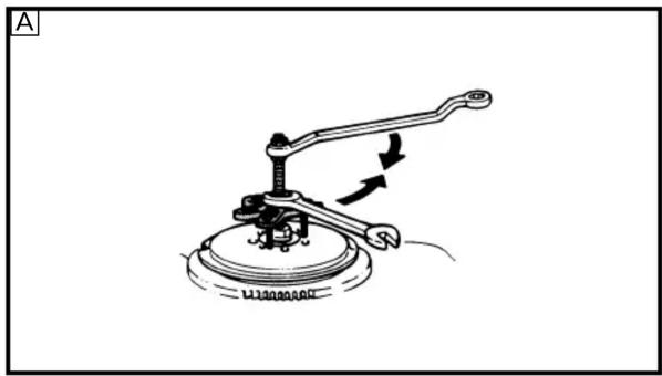
natural_image
Mechanical device with lever mechanism and directional arrows indicating motion (no text or symbols)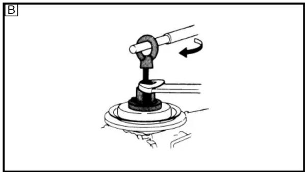
natural_image
Mechanical assembly diagram showing a lever mechanism with a rotating arrow (no text or symbols)CAUTION:
The major load should be applied in the direction of the arrows. If the load is not applied as shown, the flywheel holder may easily slip off.
REMOVING THE FLYWHEEL MAGNET ASSEMBLY
- Remove:
• Flywheel magnet assembly nut

Flywheel magnet assembly holder YB-06139 / 90890-06522
A For USA and Canada
B For worldwide
- Remove:
• Flywheel magnet assembly
| Universal puller YB-06117 / 90890-06521 |
A For USA and Canada
B For worldwide
CAUTION:
- Keep the nut side flush with the crankshaft end until the flywheel magnet assembly comes off the tapered portion of the crankshaft.
- To prevent damage to the engine or tools, screw in the universal-puller set-bolts evenly and completely so that the universal-puller plate is parallel to the fly-wheel magnet assembly.
POWR

ATTENTION:
natural_image
Mechanical diagram showing a tool interacting with a gear mechanism, no text or symbols present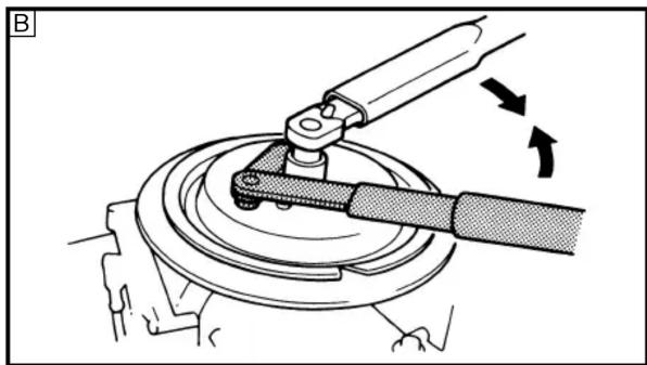
natural_image
Mechanical diagram showing a lever mechanism interacting with a circular component, with no visible text or symbols.INSTALLING THE FLYWHEEL MAGNET ASSEMBLY
Install:
• Flywheel magnet assembly nut

Flywheel magnet assembly holder YB-06139 / 90890-06522
A For USA and Canada
B For worldwide

Flywheel magnet assembly nut 190 Nm (19.0 m · kgf, 137 ft · lb)
POWR

ENSEMBLE DE VOLANT MAGNETIQUE
| Order | Job/Part Q'ty Remarks | ||
| Battery leads Disconnect the leads | form the battery terminals. | ||
| Low-pressure fuel line Refer to “LOW-PRESSURE FUEL LINE” on page 4-26. | |||
| 1 Bolt 2 | |||
| 2 Grommet retaining plate 1 | |||
| 3 Bolt 1 | |||
| 4 Hose locating plate 1 | |||
| 5 Clip 2 | |||
| Continued on next page. | |||
MOTEUR
DECONNECTER/CONNECTER DU CABLE DE COMMANDE
| Order | Job/Part Q'ty Remarks | ||
| 1 | Junction box cover 1 | ||
| 2 | Wire harness coupler 1 For the remote control box. | ||
| 3 | Warning lamp coupler 1 | ||
| 4 | Bolt 1 | ||
| 5 | Negative battery lead 1 | ||
| 6 | Nut 1 | ||
| 7 | Washer 2 | ||
| 8 | Positive battery lead 1 | ||
| 9 | Bolt 1 | ||
| 10 | PTT motor lead (sky blue) 1 | ||
| 11 | Bolt 1 | ||
| Continued on next page. |
DECONNECTER/CONNECTER DES FILS
| Order | Job/Part Q'ty Remarks | ||
| 1 | Bolt 2 | ||
| 2 | Nut 2 | ||
| 3 | Bolt 5 | ||
| 4 | Apron 1 | ||
| 5 | Bolt 6 | ||
| 6 | Bolt 2 | ||
| 7 | Power unit 1 | ||
| 8 | Gasket 1 | Not reusable | |
| 9 | Dowel pin 2 | For installation, reverse the removal procedure. |
DEPOSE/INSTALLATION DU MOTEUR
STATOR COIL ASSEMBLY
REMOVING/INSTALLING THE STATOR COIL ASSEMBLY

| Order | Job/Part Q'ty Remarks | ||
| Flywheel magnet assembly Refer to “FLYWHEEL MAGNET ASSEMBLY” on page 5-1. | |||
| 1 Stator coil coupler 12 Rectifier/regulator connector 13 Bolt 14 Screw 15 Bolt 36 Lighting coil assembly 17 Pulser coil connector 18 Bolt 49 Base 1 | |||
| For installation, reverse the removal procedure. | |||
ENSEMBLE DE LA BOBINE DE STATOR
DEPOSE/INSTALLATION DE L'ENSEMBLE DE LA BOBINE DE STATOR
REMOVING/INSTALLING THE TIMING BELT

| Order | Job/Part Q'ty Remarks | ||
| Stator coil assembly Refer to “STATOR COIL ASSEMBLY” on 1 Bolt 22 Flywheel cover bracket 13 Plastic locking tie 14 Hose clamp 15 Hose 16 Driven sprocket bolt 27 Washer 28 Driven sprocket 2 | page 5-9.Not reusableContinued on next page. |
COURROIE DE SYNCHRONISATION
DEPOSE/INSTALLATION DE LA COURROIE DE SYNCHRONISATION
Make sure cylinder #1's position is at TDC before removal.
Remove:
- Bolt

Flywheel magnet assembly holder YB-06139 / 90890-06522
A For USA and Canada
B For worldwide

natural_image
Technical line drawing of mechanical components including a wrench, screwdriver, and gear assembly (no text or labels)REMOVING/INSTALLING THE DRIVE SPROCKET
- Remove:
- Nut

Crankshaft holder YB-06552 / 90890-06552
NOTE:
A deep socket (46 mm, 76 mm deep) is required for this service.
-
Install:
-
Woodruff key ①
- Pick-up rotor ②
- Drive sprocket ③
- Drive sprocket nut ④

Drive sprocket nut 265 Nm (27.0 m · kgf, 192 ft · lb)

Crankshaft holder YB-06552 / 90890-06552

POWR

DEPOSE DE LA ROUE DENTEE MENEE
ATTENTION:
A For USA and Canada
B For worldwide

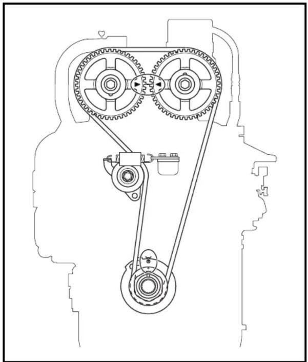
natural_image
Technical line drawing of a mechanical gear assembly with no visible text or symbolsINSTALLING THE TIMING BELT
CAUTION:
- Never forcefully twist, turn inside out, or bend the timing belt.
- Do not let oil or grease get onto the timing belt.
• Ⓐ Minimum 25 mm (1.0 in)
Install:
- Timing belt
- Tensioner
Installation steps
(1) Align 6 hole on the pickup rotor with the notch in the cylinder block.
(2) Align the marks “▼” on the driven sprockets with the top edge of the cylinder head.
(3) Install the timing belt onto the driven sprockets and drive sprocket.
(4) Install the tensioner.

Tensioner bolt 40 Nm (4.0 m · kgf, 29 ft · lb)
(5) Turn the crankshaft clockwise two times and make sure the drive sprocket and driven sprockets are correctly aligned with the marks.
POWR

INSTALLATION DE LA ROUE DENTEE MENEE
Installer:
(6,0 m • kgf, 43 ft • lb)

(4,0 m • kgf, 29 ft • lb)
(6,0 m · kgf, 43 ft · lb)

Schwungradmagnet-
auteilhalter
YB-06139 /
90890-06522
(4,0 m · kgf, 29 ft · lb)
(6,0 m • kgf, 43 ft • lb)

(4,0 m • kgf, 29 ft • lb)
IGNITION COILS AND STARTER MOTOR REMOVING/INSTALLING THE IGNITION COILS AND STARTER MOTOR

| Order | Job/Part Q'ty Remarks | ||
| 1 Ignition coil coupler 2 | |||
| 2 Bolt 4 | |||
| 3 Ignition coil 2 | |||
| 4 Spark plug 4 | |||
| 5 Screw 1 | |||
| 6 Relay (magnetic switch) lead 1 | |||
| 7 Nut 1 | |||
| 8 Wire harness lead 2 | |||
| 9 Bolt 3 | |||
| 10 Starter motor 1 | |||
| For installation, reverse the removal procedure. | |||
BOBINES D'ALLUMAGE ET MOTEUR DE DEMARREUR
DEPOSE/INSTALLATION DES BOBINES D'ALLUMAGE ET DU MOTEUR DE DEMARREUR
ECM AND JUNCTION BOX ASSEMBLY
REMOVING/INSTALLING THE CDI UNIT AND JUNCTION BOX ASSEMBLY

| Order | Job/Part Q'ty Remarks | ||
| 1 | ECM coupler 2 | ||
| 2 | Bolt 4 | ||
| 3 | E C M 1 | ||
| 4 | Collar 8 | ||
| 5 | Grommet 1 | ||
| 6 | Bolt 2 | ||
| 7 | Rectifier/regulator 1 | ||
| 8 | Bolt 1 | ||
| 9 | Ground lead 2 | ||
| 10 | Bolt 1 | ||
| 11 | Ground lead 3 | ||
| Continued on next page. |
ECM ET ENSEMBLE DE BOITE D'ACCOUPLEMENT
DEPOSE/INSTALLATION DU BLOC CDI ET DE L'ENSEMBLE DE BOITE D'ACCOUPLEMENT
| Order | Job/Part Q'ty Remarks | ||
| 12 | Bolt 1 | ||
| 13 | Ground lead 2 | ||
| 14 | Water temperature sensor coupler | 1 | |
| 15 | Bolt 2 | ||
| 16 | Clamp 2 | ||
| 17 | Bolt 5 | ||
| 18 | Junction box assembly 1 | ||
| 19 | Throttle position sensor coupler 1 | ||
| 20 | Intake air pressure sensor coupler | 1 | |
| Continued on next page. |
| Order | Job/Part Q'ty Remarks | ||
| 1 | Screw 1 | ||
| 2 | Main relay coupler 1 | ||
| 3 | Main relay 1 | ||
| 4 | Bolt 2 | ||
| 5 | PTT relay coupler 1 | ||
| 6 | PTT relay 1 | ||
| 7 | Screw 1 | ||
| 8 | Plate 1 | ||
| 9 | Screw 1 | ||
| Continued on next page. |
DEMONTAGE/MONTAGE DE L'ENSEMBLE DE BOITE D'ACCOUPLEMENT
| Order | Job/Part Q'ty Remarks | ||
| 10 | Positive battery lead 1 | ||
| 11 | Starter relay coupler 1 | ||
| 12 | Starter relay 1 | ||
| 13 | Screw 1 | ||
| 14 | Diagnostic coupler 1 | ||
| 15 | Fuse holder 4 | ||
| 16 | Clip 1 | ||
| 17 | Wire harness 1 | ||
| 18 | Junction box 1 | ||
| For assembly, reverse the disassembly procedure. |
| Order | Job/Part Q'ty Remarks | ||
| Timing belt and driven sprockets Refer to 1 Oil filler cap 12 Bolt 143 Cylinder head cover 14 Rubber gasket 15 Screw 86 Breather cover 17 Bolt 28 Fuel pump bracket assembly 1 | “TIMING BELT” on page 5-10.For installation, reverse the removal procedure. |
COUVERCLE DE CULASSE
DEPOSE/INSTALLATION DU COUVERCLE DE CULASSE
REMOVING/INSTALLING THE CAMSHAFTS

| Order | Job/Part Q'ty Remarks | ||
| Cylinder head cover Refer to “CYLINDER | HEAD COVER” on page 5-20. | ||
| 1 Bolt 16 | |||
| 2 Bolt 4 | |||
| 3 Camshaft cap 2 | |||
| 4 Camshaft cap 8 | |||
| 5 Oil seal 2 | |||
| 6 Camshaft 2 | For installation, reverse the removal procedure. |
ARBRES A CAMES
DEPOSE/INSTALLATION DES ARBRES A CAMES
natural_image
Technical illustration of two micrometer calipers (a and b) with no visible text or symbols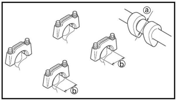

CHECKING THE CAMSHAFT
1. Measure:
- Camshaft lobe dimensions ⓐ and ⓑ Out of specification → Replace the camshaft.

Camshaft lobe dimension
a IN: 37.22 - 37.38 mm
(1.465 - 1.472 in)
⑥ IN: 29.92 - 30.08 mm
(1.178 - 1.184 in)
① EX: 36.90 - 37.06 mm
(1.453 - 1.459 in)
⑥ EX: 29.92 - 30.08 mm
(1.178 - 1.184 in)
2. Measure:
- Camshaft journal diameter ⓐ
- Camshaft cap inside diameter ⑥ Out of specification → Replace the camshaft or cylinder head.

Camshaft journal diameter
(a): 24.96 - 24.98 mm
(0.9827 - 0.9835 in)
Camshaft cap inside diameter
⑥: 25.000 - 25.021 mm
(0.984 - 0.985 in)
INSTALLING THE CAMSHAFT
Install:
- Camshaft
- Camshaft cap
Installation steps
(1) Before installing the exhaust and intake camshafts, turn the crankshaft until cylinder #1's piston is at TDC on the compression stroke.
(2) Install the camshaft caps in the proper position as shown and with the stamped numbers facing upside down.
VERIFICATION DES ARBRES A CAMES
1. Mesurer:
| Order | Job/Part Q'ty Remarks | ||
| Camshafts Refer to “CAMSHAFTS” on page 5-21.Intake assembly Refer to “INTAKE ASSEMBLY” onpage 4-3.1 Bolt (1.5 mm thread pitch) 102 Bolt 53 Cylinder head assembly 14 Gasket 15 Dowel pin 2 | |||
| Not reusableContinued on next page. |
*: Torque value (for reference only)
ENSEMBLE DE CULASSE
DEPOSE/INSTALLATION DE L'ENSEMBLE DE CULASSE
CHECKING THE THERMOSTAT
1. Check:
- Thermostat Damage/valve does not open → Replace.
2. Measure:
- Valve operating temperature
- Valve lift @ Out of specification → Replace the thermostat.
 | Water temperature Valve lift | |
| Below 50°C (122°F) | 0 mm (0 in) | |
| Above 60°C (140°F) | Min. 4.3 mm (0.17 in) | |
Measuring steps
(1) Suspend the thermostat in a container filled with water.
(2) Slowly heat the water.
(3) Place a thermometer in the water.
(4) While stirring the water, observe the thermometer's indicated temperature.
POWR

VERIFICATION DU THERMOSTAT
1. Vérifier:
REMOVING/INSTALLING THE VALVES
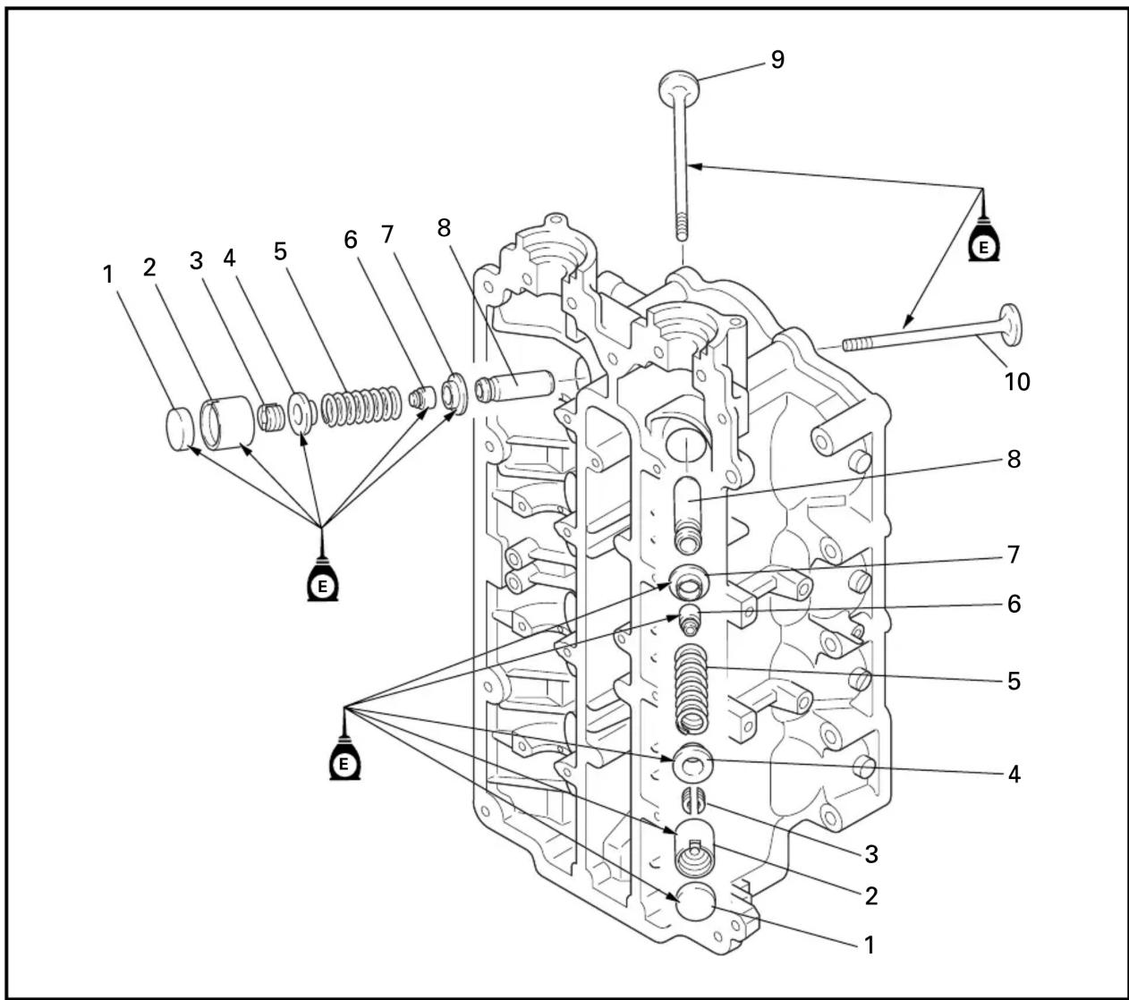
| Order | Job/Part Q'ty Remarks | ||
| Camshaft and cylinder head assembly | Refer to “CAMSHAFTS” on page 5-21 and “CYLINDER HEAD ASSEMBLY” on page 5-23. | ||
| 1 Valve pad 16 | |||
| 2 Valve lifter 16 | |||
| 3 Valve cotter 32 | |||
| 4 Spring retainer 16 | |||
| 5 Valve spring 16 | |||
| Continued on next page. | |||
SOUPAPES
DEPOSE/INSTALLATION DES SOUPAPES
| Order | Job/Part Q'ty Remarks | ||
| 6 | Valve stem seal 16 | ||
| 7 | Spring seat 16 | ||
| 8 | Valve guide 16 | ||
| 9 | Intake valve 8 | ||
| 10 | Exhaust valve 8 | For installation, reverse the removal procedure. |
Out of specification → Replace.

Margin thickness
IN: 0.8 - 1.2 mm
(0.031 - 0.047 in)
EX: 1.0 - 1.4 mm
(0.039 - 0.055 in)

- Measure:
- Valve stem diameter ⓐ
Out of specification → Replace.

Valve stem diameter
IN: 5.975 - 5.990 mm
(0.2352 - 0.2358 in)
EX: 5.960 - 5.975 mm
(0.2346 - 0.2352 in)

natural_image
Line drawing of a mechanical gauge or dial mounted on a lever, with no visible text or symbols.- Measure:
- Valve stem runout
Out of specification → Replace.

Valve stem runout limit
IN and EX
0.03 mm (0.001 in)
NOTE:
The valve guide, valve seal, and valve should be replaced as a set.
POWR

VERIFICATION DE LA SOUPAPE
- Vérifier:
- Soupape
natural_image
Technical line drawing of an internal combustion engine cylinder head with bolt holes and flow arrows indicating motion (no text or labels)

natural_image
Technical line drawing of a mechanical component with a tool inserted, showing internal structure and motion direction (no text or symbols)CHECKING THE VALVE SPRING
- Measure:
- Free length ⓐ
Out of specification → Replace.

Free length limit 52.25 mm (2.057 in)
- Measure:
- Valve spring tilt ⓐ
Out of specification → Replace.

Valve spring tilt limit IN and EX 2.6 mm (0.10 in)
CHECKING THE CYLINDER HEAD
Measure:
- Cylinder head warpage
Out of specification → Reface or replace.

Warpage limit 0.1 mm (0.004 in)
CHECKING THE VALVE GUIDE
Measure:
- Valve guide bore ⓐ
Out of specification → Replace the guide.

Valve guide bore 6.005 - 6.018 mm (0.2364 - 0.2369 in)
Replacement steps
(1) Remove the valve guide with the valve guide remover/installer.

Valve guide remover YM-4064-A / 90890-04064
POWR

SOUPAPES
VENTILE
VÁLVULAS
VERIFICATION DU RESSORT DE SOUPAPE
- Mesurer:
- Longueur libre ⓐ

natural_image
Technical line drawing of a mechanical component with internal structure (no text or symbols)(2) Install the new valve guide to the specified position (from the top of the valve guide bore as shown) @ with the valve guide remover/installer.

Valve guide position 11.5 mm (0.45 in)
(3) After installing the valve guide, bore the valve guide with the valve guide reamer.

Valve guide reamer YM-04066 / 90890-04066
NOTE:
- Heat the cylinder head in an oven to 200°C (392°F) to ease valve guide removal and installation, and to maintain the correct interference fit.
- Before installing the valve guide, mark its installation position ⑥ as shown.

CHECKING THE VALVE SEAT
1. Measure:
- Valve seat width ⓐ Out of specification → Reface the valve seat.

Valve seat width Intake
1.58 - 1.94 mm (0.062 - 0.076 in)
Exhaust 1.80 - 2.02 mm (0.071 - 0.080 in)
2. Reface:
- Valve seat
CAUTION:
To prevent chatter marks, turn the valve seat cutter while an even, downward pressure (4 - 5 kg).
POWR

SOUPAPES VENTILE VÁLVULAS
- Refer to the following chart to determine the appropriate valve seat cutter.
| Valve seat area Valve seat cutter | |
| A 90° | |
| B 45° | |
NOTE: ____
After refacing the valve seat or replacing the valve and valve guide, lap the valve seat and valve face.

INSTALLING THE VALVE
-
Install:
-
Valve stem seal ①
- Valve ②
- Spring seat ③
- Valve spring ④
-
Spring retainer ⑤
-
Install:
- Valve cotter ⑥

Valve spring compressor
YM-01253 / 90890-04019
Valve spring compressor adapter
YB-06554 / 90890-06554
NOTE: ____
Compress the valve spring with the special tools and install the cotters onto the valve.

OIL FILTER AND EXHAUST COVER
REMOVING/INSTALLING THE OIL FILTER AND EXHAUST COVER
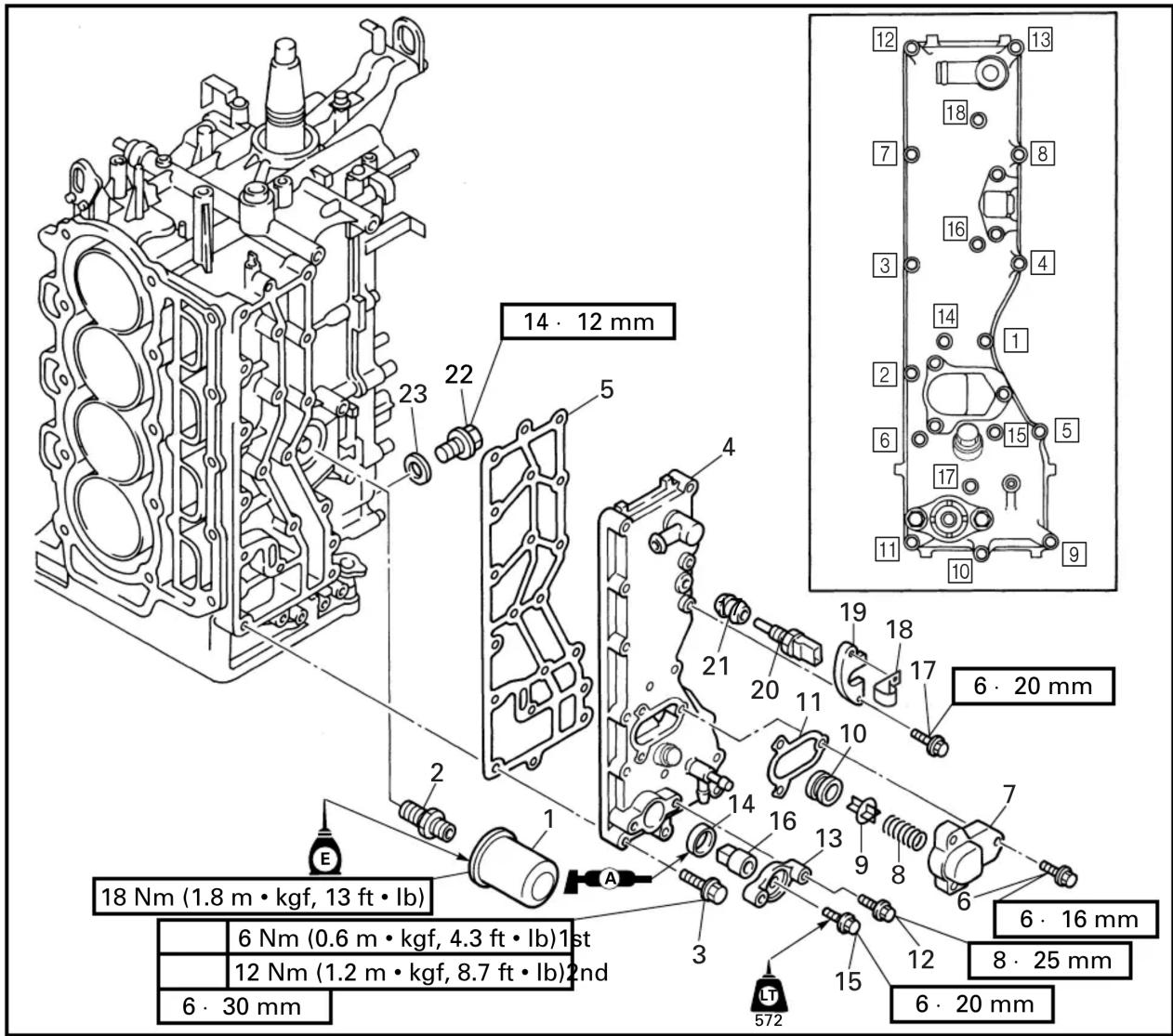
| Order | Job/Part Q'ty Remarks | ||
| Camshafts and cylinder head assembly | Refer to “CAMSHAFTS” on page 5-21 and “CYLINDER HEAD ASSEMBLY” on page 5-23. | ||
| 1 Oil filter 1 | |||
| 2 Oil filter stand 1 | |||
| 3 Bolt 18 | |||
| 4 Exhaust cover 1 | |||
| 5 Gasket 1 | Not reusable | ||
| 6 Bolt 3 | |||
| 7 Pressure control valve (PCV) cover | 1 | ||
| Continued on next page. | |||
FILTRE A HUILE ET CACHE D'ECHAPPEMENT
DEPOSE/INSTALLATION DU FILTRE A HUILE ET DU CACHE D'ECHAPPEMENT
| Order | Job/Part Q'ty Remarks | ||
| 8 Spring 19 Pressure control valve (PCV) 1 Face the longer side towards the cylinder block. | |||
| 10 Grommet 11 Gasket 112 Bolt 213 Anode cover 114 O-ring 115 Bolt 116 Anode 1 | Not reusable | ||
| Continued on next page. | |||
| Order | Job/Part Q'ty Remarks | ||
| 17 | Bolt 2 | ||
| 18 | Metal clamp 1 | ||
| 19 | Engine temperature sensor retainer | 1 | |
| 20 | Engine temperature sensor 1 | Not reusable | |
| 21 | Gasket 1 | ||
| 22 | Drain plug 1 | ||
| 23 | Washer 1 | For installation, reverse the removal procedure. |
OIL FILTER AND EXHAUST COVER
E

natural_image
Mechanical assembly diagram showing a rotating component with directional arrows indicating motion (no text or labels)INSTALLING THE OIL FILTER
Install:
- Oil filter
 | Oil filter18 Nm (1.8 m • kgf, 13 ft • lb) |
 | Oil filter wrenchYU-38411 / 90890-01426 |
Refer to "REPLACING THE ENGINE OIL/OIL FILTER" on page 3-11.
POWR

FILTRE A HUILE ET CACHE D'ECHAPPEMENT
ÖLFILTER UND AUSPUFFABDECKUNG
FILTRO DEL ACEITE Y CUBIERTA DEL ESCAPE

INSTALLATION DU FILTRE A HUILE
Installer:
- Filtre à huile

Filtre à huile
18 Nm
(1,8 m • kgf, 13 ft • lb)

CRANKSHAFT AND PISTON/CONNECTING ROD ASSEMBLY REMOVING/INSTALLING THE CRANKSHAFT AND PISTON/CONNECTING ROD ASSEMBLY

| Order | Job/Part Q'ty Remarks | ||
| Oil filter and exhaust cover Refer to “OIL FILTER AND EXHAUST COVER” on page 5-32. | |||
| 1 Bolt 2 | |||
| 2 Washer 2 | |||
| 3 Bracket 2 | |||
| 4 Oil pressure switch 1 | |||
| 5 Bolt 10 | |||
| 6 Bolt (1.5 mm thread pitch) 10 | |||
| 7 Crankcase 1 | |||
| Continued on next page. | |||
*: Torque value (for reference only)
VILEBREQUIN ET ENSEMBLE PISTON/BIELLE
DEPOSE/INSTALLATION DU VILEBREQUIN ET DE L'ENSEMBLE PISTON/BIELLE
| Order | Job/Part Q'ty Remarks | ||
| 8 | Connecting rod bolt 8 | Not reusable | |
| 9 | Connecting rod cap 4 | ||
| 10 | Crankshaft 1 | ||
| 11 | Main bearing 5 | ||
| 12 | Big end bearing 4 | ||
| 13 | Piston/connecting rod assembly 4 | ||
| 14 | Oil seal 1 | ||
| 15 | Oil seal 1 | ||
| 16 | Cylinder block 1 | ||
| For installation, reverse the removal procedure. |

CHECKING THE CYLINDER BLOCK
Measure:
- Cylinder bore
Out of specification → Rebore the cylinder or replace the cylinder block.
| Standard | Wear limit | |
| Cylinder bore “D” | 79.000 - 79.020 mm(3.110 - 3.111 in) | — |
| Taper limit “T” | — | 0.08 mm(0.003 in) |
| Out of round limit | — | 0.08 mm(0.003 in) |
| D = Maximum Dia. (D1 - D6)T = (maximum D1 or D2) – (minimum D5 or D6) | ||
NOTE:
Measure the cylinder bore in parallel and at a right angle to the crankshaft. Then, average the measurements.
CHECKING THE PISTON
Measure:
- Piston diameter
Out of specification → Replace the piston.
| Distancea | Piston diameter | |
| Standard | 13 mm(0.51 in) | 78.928 - 78.949 mm(3.1074 - 3.1082 in) |
| Oversize piston diameterOversize 1: + 0.25 mm (0.001 in) |
VERIFICATION DU BLOC DE CYLINDRE
Mesurer:
CALCULATING THE PISTON-TO-CYLINDER CLEARANCE
Calculate:
- Piston-to-cylinder clearance
Out of specification → Replace the piston and piston rings, the cylinder block or both.
| Piston-to-cylinder clearance | = | Cylinder bore | - | Piston diameter |

Piston-to-cylinder clearance
0.070 - 0.080 mm
(0.0028 - 0.0031 in)

CHECKING THE PISTON RING
- Measure:
- End gap ⓐ
Out of specification → Replace the piston rings as a set.

End gap (installed)
Top ring
0.15 - 0.30 mm
(0.006 - 0.012 in)
2nd ring
0.70 - 0.90 mm
(0.028 - 0.035 in)
Oil ring
0.20 - 0.70 mm
(0.008 - 0.028 in)
NOTE:
Push the piston ring into the cylinder with the piston crown.
POWR

VILEBREQUIN ET ENSEMBLE PISTON/BIELLE KURBELWELLE UND KOLBEN/PLEUELSTANGEN-BAUTEIL CONJUNTO DE CIGÜEÑAL Y PISTÓN/BIELA

CALCUL DU JEU PISTON/ CYLINDRE
Calculator:
- Jeu piston/cylindre
2. Measure:
- Side clearance ⓐ
Out of specification → Replace the piston and piston rings as a set.

Side clearance
Top ring
0.02 - 0.08 mm
(0.001 - 0.003 in)
2nd ring
0.03 - 0.07 mm
(0.001 - 0.003 in)
Oil ring
0.03 - 0.15 mm
(0.001 - 0.006 in)

CHECKING THE CRANKSHAFT
Measure:
• Crankshaft journal diameter
- Crank pin diameter
- Crankshaft runout
Out of specification → Replace the crankshaft.

Crankshaft journal diameter limit
47.972 mm (1.8887 in)
Crankshaft runout limit
0.03 mm (0.001 in)
CHECKING THE MAIN-BEARING OIL CLEARANCE
1. Measure:
- Main-bearing oil clearance
Out of specification → Replace the upper and lower bearings as a set.

Main-bearing oil clearance
0.024 - 0.044 mm
(0.0009 - 0.0017 in)
NOTE:
Measure the main-bearing oil clearance at room temperature (20 °C (68 °F)).
POWR

VILEBREQUIN ET ENSEMBLE PISTON/BIELLE KURBELWELLE UND KOLBEN/PLEUELSTANGEN-BAUTEIL CONJUNTO DE CIGÜEÑAL Y PISTÓN/BIELA
2. Mesurer:
- Jeu latéral ⓐ

natural_image
Technical line drawing of a mechanical assembly with no visible text or symbols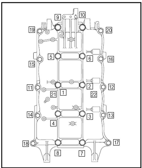

natural_image
Line drawing of a hand using a tool to adjust or install a mechanical component (no text or symbols present)Measuring steps
CAUTION:
Install the bearings in their original positions. Incorrect oil clearance measurements can lead to engine damage.
(1) Clean the bearings, main journals, and bearing portions of the crankcase and cylinder block.
(2) Place the cylinder block upside down on a bench.
(3) Install half of the bearings ① and the crankshaft ② into the cylinder block ③.
(4) Put a piece of Plastigauge on each main journal in parallel to the crankshaft.
NOTE:
Do not put the Plastigauge ^® over the oil hole in the main journal of the crankshaft.
(5) Install the other half of the bearings into the crankcase.
(6) Install the crankcase onto the cylinder block.
(7) Apply engine oil on to the threads and seat of the crankcase bolts.
(8) Tighten the bolts to the specified torque in two steps in the order shown in the illustration.
NOTE:
Do not move the crankshaft until the main-bearing oil clearance measurement has been completed.

Bolt (M8)
1st: 14 Nm (1.4 m · kgf, 10 ft · lb)
2nd: 28 Nm (2.8 m · kgf, 20 ft · lb)
Bolt (M10)
1st: 19 Nm (1.9 m · kgf, 14 ft · lb)
2nd: 60°
50 Nm
(5.0 m · kgf, 36 ft · lb)*
(9) Remove the crankcase.
(10) Measure the width of the compressed Plastigauge ^® on each main journal.
* Torque valve (for reference only)
Etapes de la mesure
ATTENTION:
- Main-bearing oil clearance
NOTE:
Adjust the main-bearing oil clearance at room temperature (20°C (68°F)).
Adjusting steps
CAUTION:
Remove any oil or dust from the cylinder block and crankcase bearing mounting surfaces.
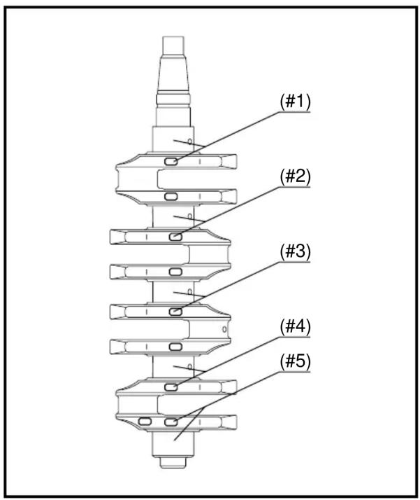


natural_image
Technical line drawing of a cylindrical mechanical component with a side tab and central hole (no text or symbols)NOTE:
The cylinder block journal diameters (#1 - #5) and the crankshaft journal diameters, (#1 - #5) can be determined by the stamped value as described below.
Crankshaft journal diameter = 47.900 + (stamped value/1000)
Example: #1 = 92 → 47.992
Cylinder block journal diameter = 54.000 + (stamped value/1000)
Example: #1 = 32 → 54.032
(1) Subtract the crankshaft journal diameters (#1 - #5) from the cylinder block journal diameters (#1 - #5).
(2) Select the suitable bearing from the table below according to the calculated values.
| Crankshaft bearing selection table (20 °C (68 °F)) | ||
| Cylinder block journal diameters – crankshaft journal diameters (mm) | Bearing (cylinder side)/ thrust bearing | Bearing (crankcase side) |
| 6.023 - 6.026 | Green | Yellow* |
| 6.027 - 6.034 | Blue | Green* |
| 6.035 - 6.042 | Blue | Blue |
| 6.043 - 6.049 | Red | Blue* |
| 6.050 - 6.058 | Red | Red |
POWR

VILEBREQUIN ET ENSEMBLE PISTON/BIELLE KURBELWELLE UND KOLBEN/PLEUELSTANGEN-BAUTEIL CONJUNTO DE CIGÜEÑAL Y PISTÓN/BIELA

2. Régler:
The (*) mark indicates that the color of the upper and lower bearings are different. Install the main-bearings in the middle of the cylinder block and crankcase journal so they do not block the oil holes.
NOTE: \_\_\_\_
Crankshaft bearing #3 is a thrust bearing.
(3) If the difference between the cylinder block journal diameter and crankshaft journal diameter is more than the maximum value (6.058 mm), replace the crankshaft, cylinder block, or both.
CHECKING THE CONNECTING ROD BIG-END OIL CLEARANCE
CAUTION:
- Mark the original connecting rod bolts so they are not confused with the new bolts.
- Do not reuse the original connecting rod bolts during assembly, only use them when measuring and adjusting the oil clearance.
- Before assembly, remove any small metal particles from the big-end mating surface and also thoroughly clean it.
1. Measure:
- Big-end oil clearance Out of specification → Replace the upper and lower bearings as a set.

Big-end oil clearance 0.025 - 0.031 mm (0.0010 - 0.0012 in)
NOTE: \_\_\_\_
Measure the big-end oil clearance at room temperature (20 °C (68 °F)).
POWR

VILEBREQUIN ET ENSEMBLE PISTON/BIELLE KURBELWELLE UND KOLBEN/PLEUELSTANGEN-BAUTEIL CONJUNTO DE CIGÜEÑAL Y PISTÓN/BIELA
ATTENTION:
natural_image
Technical line drawing of a mechanical assembly with no visible text or symbols
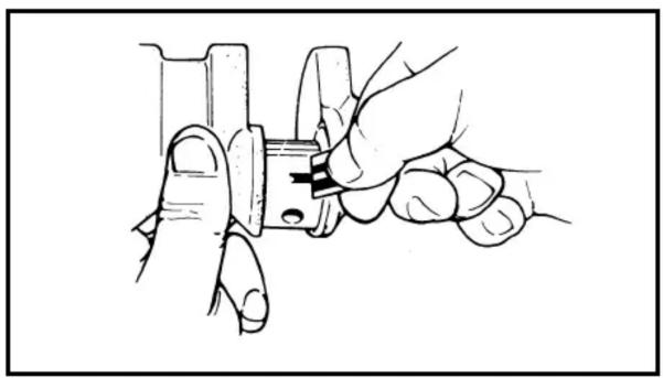
natural_image
Illustration of hands using a tool to adjust or install a mechanical component (no text or symbols visible)Measuring steps
CAUTION:
Install the bearings in their original positions. Incorrect oil clearance measurements can lead to engine damage.
(1) Clean the bearings and bearing portions of the connecting rod.
(2) Install the upper half of the bearing into the connecting rod and the lower half into the connecting rod cap.
(3) Put a piece of Plastigauge onto the crank pin in parallel to the crankshaft.
(4) Assemble the connecting rod onto the crank pin.
NOTE:
- Make sure the projections ⓐ and "YAMAHA" mark on the connecting rod faces towards the flywheel side.
- Do not move the crankshaft until the big-end oil clearance measurement has been completed.
(5) Apply engine oil onto the threads and seat of the original connecting rod bolts.
(6) Tighten the original bolts to the specified torque in two stages.

Bolt
1st: 15 Nm
(1.5 m · kgf, 11 ft · lb)
2nd: 60°
(7) Remove the connecting rod cap.
(8) Measure the width of the compressed Plastigauge ^® on each crank pin.
POWR

VILEBREQUIN ET ENSEMBLE PISTON/BIELLE KURBELWELLE UND KOLBEN/PLEUELSTANGEN-BAUTEIL CONJUNTO DE CIGÜEÑAL Y PISTÓN/BIELA

Etapes de la mesure
ATTENTION:
2^:60^
- Big-end oil clearance
NOTE:
Adjust the big-end oil clearance at room temperature (20 °C (68 °F)).

natural_image
Technical line drawing of a mechanical assembly with no visible text or symbols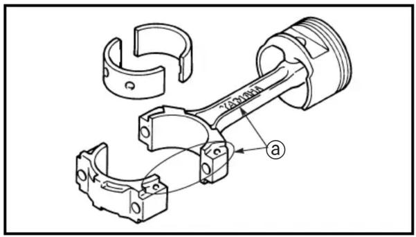
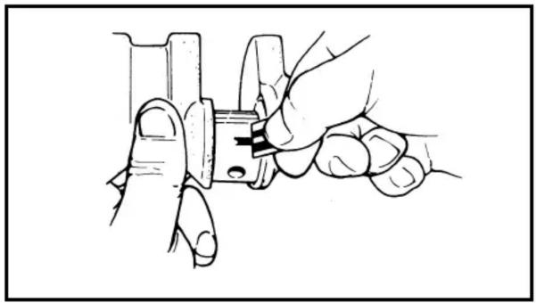
natural_image
Line drawing of a hand using a tool to adjust or install a mechanical component (no text or symbols present)Adjusting steps
CAUTION:
Remove any oil or dust from the connecting-rod-bearing mounting surfaces.
(1) Install the new yellow bearings into the connecting rods and connecting rod caps.
(2) Put a piece of Plastigauge onto the crank pin in parallel to the crankshaft.
(3) Assemble the connecting rod onto the crank pin.
NOTE:
- Make sure the projections ⓐ and "YAMAHA" mark on the connecting rod faces towards the flywheel side.
- Do not move the crankshaft until the big-end oil clearance measurement has been completed.
(4) Apply engine oil onto the threads and seat of the original connecting rod bolts.
(5) Tighten the original bolts to the specified torque in two stages.

Bolt
1st: 15 Nm
(1.5 m · kgf, 11 ft · lb)
2nd: 60°
(6) Remove the connecting rod cap.
(7) Measure the width of the compressed Plastigauge ^® on each crank pin.
(8) Select the suitable bearing from the table below according to the measurement values.
POWR

VILEBREQUIN ET ENSEMBLE PISTON/BIELLE KURBELWELLE UND KOLBEN/PLEUELSTANGEN-BAUTEIL CONJUNTO DE CIGÜEÑAL Y PISTÓN/BIELA
2. Régler:
The (*) mark indicates that the color of the upper and lower bearings are different.
(9) If the measurement value is more than the maximum value (0.071 mm), replace the crankshaft, connecting rod, or both.

INSTALLING THE PISTON RING
CAUTION:
- Do not scratch the piston or break the piston rings.
• After installing the piston rings, check that they move smoothly.
Install:
- Oil ring (#3 and #4)
- 2nd ring (#2)
- Top ring (#1)
NOTE:
- Offset the piston-ring end gaps as shown.
- Piston rings should be replaced as a set.
POWR

VILEBREQUIN ET ENSEMBLE PISTON/BIELLE KURBELWELLE UND KOLBEN/PLEUELSTANGEN-BAUTEIL CONJUNTO DE CIGÜEÑAL Y PISTÓN/BIELA
| F |
| D |
| ES |
Install the piston with the "UP" mark on the piston crown facing towards the fly-wheel side.
Install:
- Piston

Piston ring compressor YU-33294 / 90890-06530
POWR

VILEBREQUIN ET ENSEMBLE PISTON/BIELLE KURBELWELLE UND KOLBEN/PLEUELSTANGEN-BAUTEIL CONJUNTO DE CIGÜEÑAL Y PISTÓN/BIELA
| F |
| D |
| ES |
INSTALLATION DU PISTON
ATTENTION:
REMOVING/INSTALLING THE LOWER UNIT 6-1
REMOVING THE PROPELLER 6-3
CHECKING THE PROPELLER.... 6-3
INSTALLING THE PROPELLER.... 6-3
WATER PUMP (REGULAR ROTATION MODELS)...... 6-4
REMOVING/INSTALLING THE WATER PUMP 6-4
CHECKING THE IMPELLER HOUSING 6-6
CHECKING THE IMPELLER AND IMPELLER HOUSING CUP...... 6-6
CHECKING THE WOODRUFF KEY 6-6
INSTALLING THE IMPELLER AND IMPELLER HOUSING 6-6
SHIFT ROD ASSEMBLY (REGULAR ROTATION MODELS) 6-7
REMOVING/INSTALLING THE SHIFT ROD ASSEMBLY 6-7
REMOVING THE SHIFT ROD ASSEMBLY 6-8
CHAPITRE 6 BLOC DE PROPULSION
BLOC DE PROPULSION (MODELES
A ROTATION NORMALE)......6-1
DEPOSE/INSTALLATION DU BLOC DE PROPULSION......6-1
DEPOSE DE L'HELICE ......6-3
VERIFICATION DE L'HELICE......6-3
INSTALLATION DE L'HELICE ....6-3
POMPE A EAU (MODELES A
ROTATION NORMALE)......6-4
DEPOSE/INSTALLATION DE LA POMPE A EAU.... 6-4
VERIFICATION DU LOGEMENT DE ROUE HELICE ...... 6-6
VERIFICATION DE LA ROUE HELICE ET DE LA COUPELLE DU CARTER DE ROUE HELICE..6-6
VERIFICATION DE LA CLAVETTE DEMI-LUNE....6-6
INSTALLATION DE LA ROUE HELICE ET DU CARTER DE ROUE HELICE ....6-6
ENSEMBLE DE TIGE DE
SELECTION (MODELES A
ROTATION NORMALE)......6-7
DEPOSE/INSTALLATION DE L'ENSEMBLE DE TIGE DE SELECTION....6-7
DEPOSE DE L'ENSEMBLE DE TIGE DE SELECTION ......6-8
PROPELLER SHAFT HOUSING ASSEMBLY
(REGULAR ROTATION MODELS) 6-9
REMOVING/INSTALLING THE PROPELLER SHAFT HOUSING
ASSEMBLY 6-9
DISASSEMBLING/ASSEMBLING THE PROPELLER SHAFT
HOUSING 6-11
DISASSEMBLING/ASSEMBLING THE PROPELLER SHAFT
ASSEMBLY 6-12
REMOVING THE PROPELLER SHAFT HOUSING ASSEMBLY...... 6-13
DISASSEMBLING THE PROPELLER SHAFT HOUSING 6-13
CHECKING THE REVERSE GEAR.... 6-14
CHECKING THE BEARING.... 6-14
CHECKING THE PROPELLER SHAFT HOUSING...... 6-14
CHECKING THE DOG CLUTCH 6-15
CHECKING THE PROPELLER SHAFT 6-15
ASSEMBLING THE PROPELLER SHAFT HOUSING 6-15
ASSEMBLING THE REVERSE GEAR 6-15
INSTALLING THE PROPELLER SHAFT HOUSING ASSEMBLY...... 6-16
DRIVE SHAFT (REGULAR ROTATION MODELS)...... 6-17
REMOVING/INSTALLING THE DRIVE SHAFT 6-17
REMOVING THE DRIVE SHAFT 6-19
DISASSEMBLING THE DRIVE SHAFT HOUSING ASSEMBLY ...... 6-19
DISASSEMBLING THE FORWARD GEAR ASSEMBLY 6-19
CHECKING THE PINION 6-20
CHECKING THE DRIVE SHAFT.... 6-20
CHECKING THE DRIVE SHAFT HOUSING 6-20
CHECKING THE BEARINGS 6-20
ASSEMBLING THE FORWARD GEAR ASSEMBLY 6-20
ASSEMBLING THE DRIVE SHAFT HOUSING ASSEMBLY ...... 6-21
INSTALLING THE DRIVE SHAFT 6-22
ENSEMBLES LOGEMENT ET AR-BRE PORTE-HELICE (MODELES
A ROTATION NORMALE)......6-9
DEPOSE/INSTALLATION DU ENSEMBLES LOGEMENT ET ARBRE PORTE-HELICE......6-9
DEMONTAGE/MONTAGE DU LOGEMENT D'ARBRE PORTE- HELICE ....6-11
DEMONTAGE/MONTAGE DE ENSEMBLES ET ARBRE PORTE- HELICE ....6-12
DEPOSE DU ENSEMBLES LOGEMENT ET ARBRE PORTE- HELICE ....6-13
DEMONTAGE DU LOGEMENT DE L'ARBRE PORTE-HELICE...6-13
VERIFICATION DU PIGNON DE MARCHE ARRIERE ....6-14
VERIFICATION DU ROULEMENT......6-14
VERIFICATION DU LOGEMENT DE L'ARBRE PORTE-HELICE...6-14 VERIFICATION DE
L'EMBRAYAGE A CRABOTS ...6-15 VERIFICATION DE ARBRE
PORTE-HELICE ....6-15 MONTAGE DU LOGEMENT DE ARBRE PORTE-HELICE....6-15
MONTAGE DU PIGNON DE MARCHE ARRIERE ....6-15
INSTALLATION DU ENSEMBLES LOGEMENT ET ARBRE PORTE- HELICE ....6-16
ARBRE D'ENTRAINEMENT (MODELES A ROTATION
NORMALE) 6-17
DEPOSE/INSTALLATION DE L'ARBRE D'ENTRAINEMENT ..6-17
DEPOSE DE L'ARBRE D'ENTRAINEMENT....6-19
DEMONTAGE DE L'ENS. LOGEMENT DE ROULEMENT D'ARBRE D'ENTRAINEMENT..6-19
DEMONTAGE DE L'ENS. PIGNON DE MARCHE AVANT..6-19
VERIFICATION DU PIGNON.....6-20 VERIFICATION DE L'ARBRE
D'ENTRAINEMENT......6-20
VERIFICATION DU LOGEMENT DE ROULEMENT D'ARBRE D'ENTRAINEMENT......6-20
VERIFICATION DES ROULEMENTS......6-20
MONTAGE DE L'ENS. PIGNON DE MARCHE AVANT ......6-20
MONTAGE DE L'ENS. LOGEMENT DE ROULEMENT D'ARBRE D'ENTRAINEMENT ....6-21
INSTALLATION DE L'ARBRE D'ENTRAINEMENT......6-22
PROPELLERWELLENGEHÄUSE-BAUTEIL (MODELLE MIT
NORMALDREHRICHTUNG) ...... 6-9
AUSBAU/EINBAU DES PROPELLERWELLENGEHÄUSE- BAUTEILS...... 6-9
DEMONTAGE/MONTAGE DES PROPELLERWELLEN- GEHÄUSES 6-11
DEMONTAGE/MONTAGE DES PROPELLERWELLEN- BAUTEILS...... 6-12
AUSBAU DES PROPELLERWEL- LENGEHÄUSE-BAUTEILS ..... 6-13
ZERLEGEN DES PROPELLER- WELLENGEHÄUSES ...... 6-13
REMOVING/INSTALLING THE LOWER UNIT 6-26
REMOVING THE PROPELLER 6-28
CHECKING THE PROPELLER.... 6-28
INSTALLING THE PROPELLER.... 6-28
WATER PUMP (COUNTER ROTATION MODELS) 6-29
REMOVING/INSTALLING THE WATER PUMP.... 6-29
CHECKING THE IMPELLER HOUSING 6-31
CHECKING THE IMPELLER AND IMPELLER HOUSING CUP...... 6-31
CHECKING THE WOODRUFF KEY 6-31
INSTALLING THE IMPELLER AND IMPELLER HOUSING 6-31
SHIFT ROD ASSEMBLY (COUNTER ROTATION MODELS) 6-32
REMOVING/INSTALLING THE SHIFT ROD ASSEMBLY 6-32
REMOVING THE SHIFT ROD ASSEMBLY 6-33
ENSEMBLE DU BLOC DE PROPULSION (MODELES A
ROTATION NORMALE)......6-23
DEMONTAGE/MONTAGE DE
L'ENSEMBLE DU BLOC DE PROPULSION....6-23
DEMONTAGE DE L'ENSEMBLE DU BLOC DE PROPULSION .....6-24
VERIFICATION DU MANCHON DE L'ARBRE D'ENTRAINEMENT...6-24
VERIFICATION DU ROULEMENT A AIGUILLES......6-24
MONTAGE DE L'ENSEMBLE DU BLOC DE PROPULSION .....6-24
BLOC DE PROPULSION (MODELES
A CONTRAROTATION) ......6-26
DEPOSE/INSTALLATION DU BLOC DE PROPULSION......6-26
DEPOSE DE L'HELICE ......6-28
VERIFICATION DE L'HELICE....6-28
INSTALLATION DE L'HELICE ..6-28
POMPE A EAU (MODELES A
CONTRAROTATION)......6-29
DEPOSE/INSTALLATION DE LA POMPE A EAU.... 6-29
VERIFICATION DU LOGEMENT DE ROUE HELICE ...... 6-31
VERIFICATION DE LA ROUE HELICE ET DE LA COUPELLE DU CARTER DE ROUE HELICE .....6-31
VERIFICATION DE LA CLAVETTE DEMI-LUNE......6-31
INSTALLATION DE LA ROUE HELICE ET DU CARTER DE ROUE HELICE ....6-31
ENSEMBLE DE TIGE DE SELECTION (MODELES A
CONTRAROTATION)......6-32
DEPOSE/INSTALLATION DE L'ENSEMBLE DE TIGE DE SELECTION....6-32
DEPOSE DE L'ENSEMBLE DE TIGE DE SELECTION ......6-33
ANTRIEBSGEHÄUSE-BAUTEIL (MODELLE MIT
NORMALDREHRICHTUNG) ..... 6-23
DEMONTAGE/MONTAGE DES ANTRIEBSGEHÄUSE- BAUTEILS.... 6-23
ZERLEGEN DES ANTRIEBSGE-HÄUSE-BAUTEILS 6-24
ÜBERPRÜFUNG DER ANTRIEBSWELLENBUCHSE..6-24 ÜBERPRÜFUNG DES NADELLAGERS...... 6-24
ZUSAMMENBAUEN DES ANTRIEBSGEHÄUSE- BAUTEILS.... 6-24
ANTRIEBSEINHEIT
(GEGENLAUFMODELLE) ...... 6-26
PROPELLER SHAFT HOUSING ASSEMBLY
(COUNTER ROTATION MODELS) 6-34
REMOVING/INSTALLING THE PROPELLER SHAFT HOUSING
ASSEMBLY 6-34
DISASSEMBLING/ASSEMBLING THE PROPELLER SHAFT
HOUSING ASSEMBLY 6-36
DISASSEMBLING/ASSEMBLING THE FRONT PROPELLER
SHAFT ASSEMBLY 6-38
REMOVING THE PROPELLER SHAFT HOUSING ASSEMBLY...... 6-39
REMOVING THE FORWARD GEAR ASSEMBLY.... 6-39
DISASSEMBLING THE PROPELLER SHAFT HOUSING
ASSEMBLY....6-40
DISASSEMBLING THE FORWARD GEAR ASSEMBLY 6-40
CHECKING THE FORWARD GEAR.... 6-41
CHECKING THE BEARING.... 6-41
CHECKING THE PROPELLER SHAFT HOUSING.... 6-41
CHECKING THE DOG CLUTCH 6-41
CHECKING THE PROPELLER SHAFTS 6-41
ASSEMBLING THE FORWARD GEAR 6-42
ASSEMBLING THE PROPELLER SHAFT HOUSING ASSEMBLY ..... 6-42
INSTALLING THE FORWARD GEAR ASSEMBLY.... 6-43
INSTALLING THE PROPELLER SHAFT HOUSING ASSEMBLY...... 6-44
ENSEMBLES LOGEMENT ET AR-BRE PORTE-HELICE (MODELES
A CONTRAROTATION) ......6-34
DEPOSE/INSTALLATION DU
ENSEMBLES LOGEMENT ET
ARBRE PORTE-HELICE......6-34
DEMONTAGE/MONTAGE DU
ENSEMBLES LOGEMENT ET
ARBRE PORTE-HELICE......6-36
DEMONTAGE/MONTAGE DE L'AR-
BRE PORTE-HELICE AVANT....6-38
DEPOSE DU ENSEMBLES
LOGEMENT ET ARBRE
PORTE-HELICE 6-39
AUSBAU DES PROPELLERWEL-
LENGEHÄUSE-BAUTEILS ..... 6-39
AUSBAU DES VORWÄRTSGE-
TRIEBEKEGELRAD-
BAUTEILS.... 6-39
ZERLEGEN DES PROPELLERWEL-
LENGEHÄUSE-BAUTEILS ..... 6-40
ZERLEGEN DES VORWÄRTSGE-
TRIEBEKEGELRADES 6-40
REMOVING THE DRIVE SHAFT 6-47
DISASSEMBLING THE DRIVE SHAFT HOUSING ASSEMBLY 6-47
DISASSEMBLING THE REVERSE GEAR 6-47
CHECKING THE PINION 6-47
CHECKING THE DRIVE SHAFT.... 6-47
CHECKING THE DRIVE SHAFT HOUSING 6-48
CHECKING THE BEARINGS 6-48
ASSEMBLING THE REVERSE GEAR ASSEMBLY.... 6-48
ASSEMBLING THE DRIVE SHAFT HOUSING ASSEMBLY 6-48
INSTALLING THE DRIVE SHAFT 6-49
LOWER CASE ASSEMBLY (COUNTER ROTATION MODELS) 6-50
DISASSEMBLING/ASSEMBLING THE LOWER CASE ASSEMBLY .... 6-50
DISASSEMBLING THE LOWER CASE ASSEMBLY 6-51
CHECKING THE DRIVE SHAFT SLEEVE 6-51
CHECKING THE NEEDLE BEARING.... 6-51
ASSEMBLING THE LOWER CASE ASSEMBLY 6-52
SHIMMING (REGULAR ROTATION MODELS)
(FOR USA AND CANADA) 6-53
SELECTING THE PINION SHIMS 6-54
SELECTING THE FORWARD GEAR SHIMS 6-56
SELECTING THE REVERSE GEAR SHIMS.... 6-58
SHIMMING (REGULAR ROTATION MODELS) (FOR WORLDWIDE) ...... 6-60
(FOR USA AND CANADA) 6-70
SELECTING THE PINION SHIMS 6-71
SELECTING THE REVERSE GEAR SHIMS.... 6-73
SELECTING THE FORWARD GEAR SHIMS 6-74
SELECTING THE PROPELLER SHAFT SHIMS.... 6-76
SHIMMING (COUNTER ROTATION MODELS) (FOR WORLDWIDE)...... 6-77
SELECTING THE PINION SHIMS 6-78
SELECTING THE REVERSE GEAR SHIMS.... 6-80
SELECTING THE FORWARD GEAR SHIMS 6-81
SELECTING THE PROPELLER SHAFT SHIMS.... 6-83
BACKLASH (COUNTER ROTATION MODELS) 6-84
MEASURING THE FORWARD GEAR BACKLASH 6-84
MEASURING THE REVERSE GEAR BACKLASH.... 6-85
JEU DE RETOUR (MODELES A ROTATION NORMALE)......6-66
MESURE DU JEU DE RETOUR DU PIGNON DE MARCHE AVANT..6-66 MESURE DU JEU DE RETOUR DU PIGNON DE MARCHE ARRIERE ....6-67
SELECTION DES CALES (MODELES A CONTRAROTATION) (POUR LES E.-U. ET LE CANADA)....6-70
SELECTION DES CALES DE PIGNON ....6-71 SELECTION DES CALES DE REGLAGE DU PIGNON DE MARCHE ARRIERE ....6-73 SELECTION DES CALES DU PIGNON DE MARCHE AVANT..6-74 SELECTION DES CALES D'ARBRE PORTE-HELICE....6-76
SELECTION DES CALES (MODELES A CONTRAROTATION)
(POUR LE RESTE DU MONDE) ..6-77 SELECTION DES CALES DE PIGNON ....6-78 SELECTION DES CALES DE REGLAGE DU PIGNON DE MARCHE ARRIERE ....6-80 SELECTION DES CALES DE REGLAGE DU PIGNON DE MARCHE AVANT ....6-81 SELECTION DES CALES D'ARBRE PORTE-HELICE....6-83
JEU DE RETOUR (MODELES A CONTRAROTATION)....6-84 MESURE DU JEU DE RETOUR DU PIGNON DE MARCHE AVANT..6-84 MESURE DU JEU DE RETOUR DU PIGNON DE MARCHE ARRIERE....6-85
REMOVING/INSTALLING THE LOWER UNIT

| Order | Job/Part Q'ty Remarks | ||
| 1 | Speedometer hose 1 | ||
| 2 | Cotter pin 1 | ||
| 3 | Propeller nut 1 | ||
| 4 | Washer 1 | ||
| 5 | Washer 1 | ||
| 6 | Propeller 1 | ||
| 7 | Spacer 1 | ||
| Continued on next page. |
BLOC DE PROPULSION (MODELES A ROTATION NORMALE)
DEPOSE/INSTALLATION DU BLOC DE PROPULSION
| Order | Job/Part Q'ty Remarks | ||
| 8 | Grommet 1 | ||
| 9 | Bolt 1 | ||
| 10 | Trim tab 1 | ||
| 11 | Bolt 1 (with washer) | ||
| 12 | Bolt 6 (with washer) | ||
| 13 | Dowel pin 2 | ||
| 14 | Lower unit 1 | ||
| For installation, reverse the removal procedure. |
natural_image
Line drawing of hands using a tool to adjust or install a wooden block (no text or symbols present)REMOVING THE PROPELLER
Remove:
- Propeller
WARNING
Do not hold the propeller with your hands when removing or installing it. Be sure to remove the battery leads from the batteries and the lanyard engine stop switch. Put a block of wood between the cavitation plate and propeller to keep the propeller from turning.
CHECKING THE PROPELLER
Check:
- Blades
- Splines
Cracks/damage/wear → Replace.

natural_image
Line drawing of a hand operating a propeller with a wooden handle (no text or symbols)INSTALLING THE PROPELLER
Install:
- Propeller
WARNING
Do not hold the propeller with your hands when removing or installing it. Be sure to remove the battery leads from the batteries and the lanyard engine stop switch. Put a block of wood between the cavitation plate and propeller to keep the propeller from turning.
NOTE:
If the groove in the propeller nut is not aligned with the cotter pin hole, tighten the nut further until they are aligned.
DEPOSE DE L'HELICE
Déposer:
• Hélice
AVERTISSEMENT
| Order | Job/Part Q'ty Remarks | ||
| Lower unit Refer to “LOWER UNIT (REGULAR ROTATION MODELS)” on page 6-1. | |||
| 1 Bolt 4 | |||
| 2 Impeller housing 1 | |||
| 3 Impeller housing cup 1 | |||
| 4 O-ring 1 | |||
| 5 O-ring 1 | |||
| 6 Grommet 1 | |||
| 7 Spacer 1 | |||
| 8 Collar 1 | |||
| Continued on next page. | |||
POMPE A EAU (MODELES A ROTATION NORMALE)
DEPOSE/INSTALLATION DE LA POMPE A EAU
Cracks/damage → Replace.
CHECKING THE IMPELLER AND IMPELLER HOUSING CUP
Check:
- Impeller
- Impeller housing cup
Cracks/damage → Replace any defective parts.
CHECKING THE WOODRUFF KEY
Check:
- Woodruff key
Damage/wear → Replace.


INSTALLING THE IMPELLER AND IMPELLER HOUSING
-
Install:
-
Washers ①
- Wave washer ②
- Spacer ③
- Collar ④
NOTE:
- The collar and spacer should fit together firmly.
-
While pulling the drive shaft up, install the collar with some appropriate tool @ that fits over the drive shaft as shown.
-
Install:
-
O-ring ①
- Impeller housing cup ②
- Impeller housing ③
- O-ring ④
NOTE:
- When installing the impeller housing cup, align its projection with the hole in the impeller housing.
- When installing the water pump housing, turn the drive shaft clockwise.
LOWR

POMPE A EAU (MODELES A ROTATION NORMALE) WASSERPUMPE (MODELLE MIT NORMALDREHRICHTUNG) BOMBA DE AGUA (MODELOS DE ROTACIÓN REGULAR)

VERIFICATION DU LOGEMENT DE ROUE HELICE
Vérifier:
- Logement de roue hélice Fissures/endommagement → Remplacer.
VERIFICATION DE LA ROUE HELICE ET DE LA COUPELLE DU CARTER DE ROUE HELICE
Vérifier:
- Roue hélice
SHIFT ROD ASSEMBLY (REGULAR ROTATION MODELS) REMOVING/INSTALLING THE SHIFT ROD ASSEMBLY
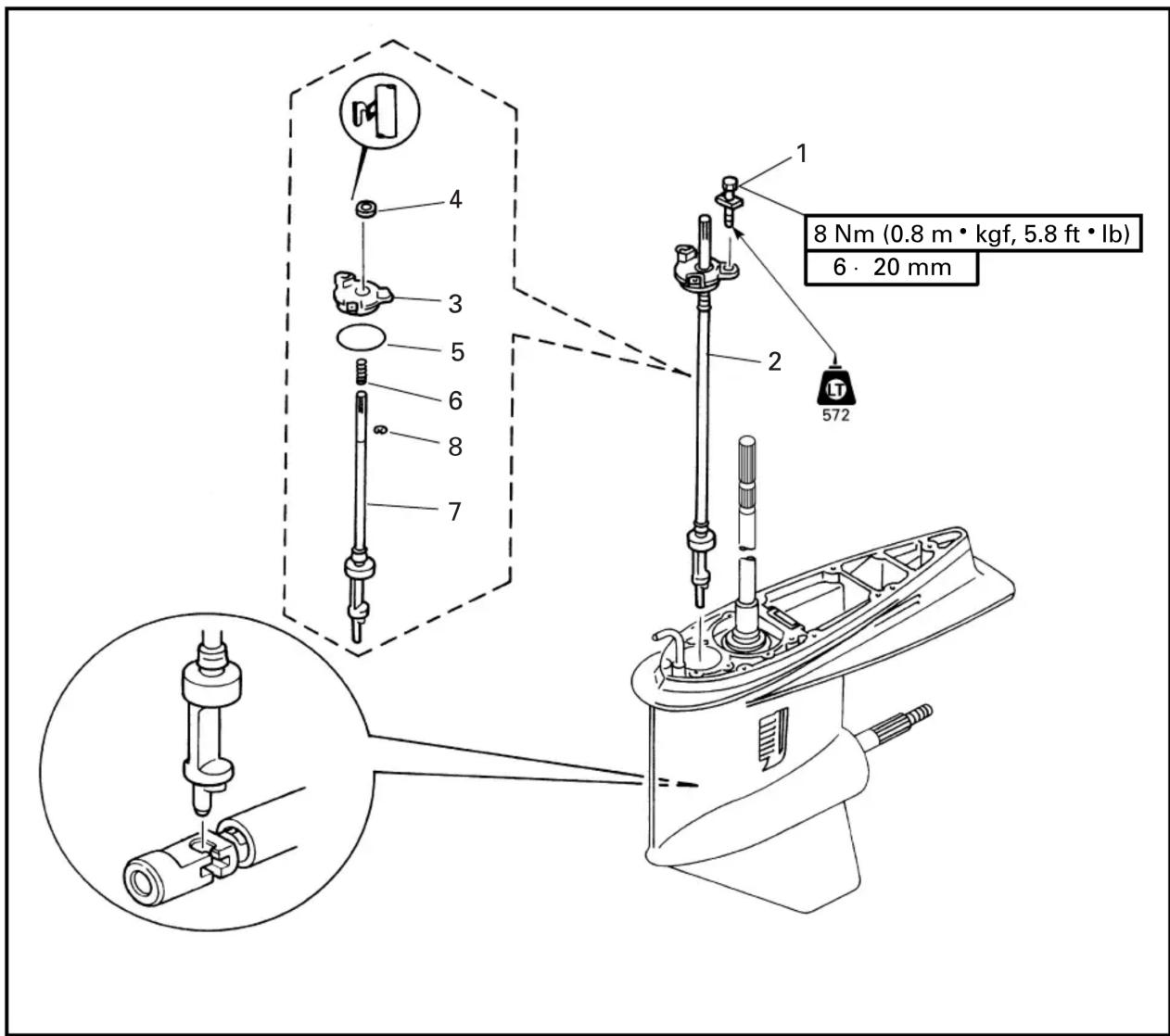
| Order | Job/Part Q'ty Remarks | ||
| Impeller plate Refer to “WATER PUMP (REGULAR ROTATION MODELS)” on page 6-4. | |||
| 1 Bolt 3 (with washer)2 Shift rod assembly 13 Oil seal housing 14 Oil seal 15 O-ring 16 Spring 17 Shift rod 18 Circlip 1 | |||
| For installation, reverse the removal procedure. | |||
ENSEMBLE DE TIGE DE SELECTION (MODELES A ROTATION NORMALE)
DEPOSE/INSTALLATION DE L'ENSEMBLE DE TIGE DE SELECTION
REMOVING THE SHIFT ROD ASSEMBLY
Remove:
- Shift rod assembly
NOTE: ____
Remove the shift rod assembly when the shift rod is in the neutral position.
DEPOSE DE L'ENSEMBLE DE TIGE DE SELECTION
Déposer:
| Order | Job/Part Q'ty Remarks | ||
| Gear oil Refer to “CHECKING THE Shift rod assembly Refer to “SHIFT ROD 1 Ring nut 12 Claw washer 13 Propeller shaft housing assembly 14 Straight key 1 | GEAR OIL LEVEL” on page 3-18.ASSEMBLY (REGULAR ROTATION MODELS)” on page 6-7.Continued on next page. | ||
ENSEMBLES LOGEMENT ET ARBRE PORTE-HELICE
(MODELES A ROTATION NORMALE)
DEPOSE/INSTALLATION DU ENSEMBLES LOGEMENT ET ARBRE PORTE-HELICE
| Order | Job/Part Q'ty Remarks | ||
| 5 | Reverse gear shim * | ||
| 6 | Propeller shaft assembly 1 | ||
| 7 | Washer 2 | ||
| 8 | Propeller shaft housing 1 | For installation, reverse the removal procedure. |
*: As required
| Order | Job/Part Q'ty Remarks | ||
| 1 | O-ring 1 | ||
| 2 | Reverse gear 1 | ||
| 3 | Thrust washer 1 | ||
| 4 | Ball bearing 1 | ||
| 5 | Oil seal 2 | ||
| 6 | Needle bearing 1 | ||
| 7 | Propeller shaft housing 1 | ||
| For assembly, reverse the disassembly procedure. |
DEMONTAGE/MONTAGE DU LOGEMENT D'ARBRE PORTE-HELICE
| Order | Job/Part Q'ty Remarks | ||
| 1 Spring 12 Pin 13 Dog clutch 14 Shift rod joint 15 Shift rod joint slider 16 Ball 27 Ball 28 Spring 19 Ball 210 Propeller shaft 1 | |||
| For assembly, reverse the disassembly procedure. | |||
DEMONTAGE/MONTAGE DE ENSEMBLES ET ARBRE PORTE-HELICE


REMOVING THE PROPELLER SHAFT HOUSING ASSEMBLY
- Straighten:
- Claw washer tabs
- Remove:
- Ring nut
- Claw washer

Ring nut wrench .... ① YB-34447 / 90890-06511
Ring nut wrench extension ..... ② 90890-06513
- Remove:
- Propeller shaft housing assembly

Propeller shaft housing puller. ① YB-06207 / 90890-06502
Universal puller.... ②
YB-06117
Guide plate.... ③
90890-06501
Center bolt 90890-06504 ④
A For USA and Canada
B For worldwide
DISASSEMBLING THE PROPELLER SHAFT HOUSING
- Remove:
- Reverse gear

Slide hammer....①
YB-06096
Bearing separator ..... ②
90890-06534
Guide plate.... ③
90890-06501
Guide plate stand ..... ④
90890-06538
Bearing puller.... ⑤
90890-06535
Small universal claws .... ⑥
90890-06536
A For USA and Canada
B For worldwide
DEPOSE DU ENSEMBLES LOGEMENT ET ARBRE PORTE- HELICE
- Redresser:
2. Remove:
- Ball bearing
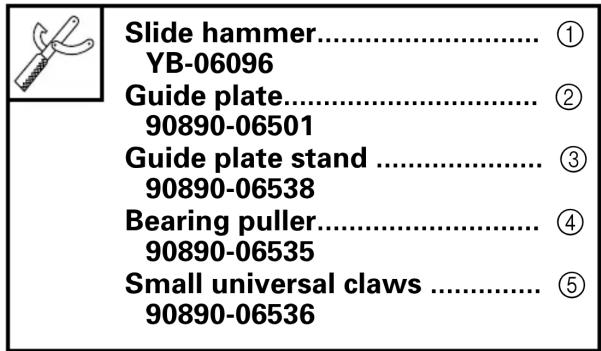
A For USA and Canada
B For worldwide
3. Remove:
- Oil seal
- Needle bearing

CHECKING THE REVERSE GEAR
Check:
- Teeth
- Dogs
Wear/damage → Replace the reverse gear.
CHECKING THE BEARING
Check:
- Bearing
Pitting/rumbling → Replace.
CHECKING THE PROPELLER SHAFT HOUSING
Check:
- Propeller shaft housing
Cracks/damage → Replace.
- Déposer:
Corrosion/grondement → Rem- placer.
VERIFICATION DU LOGEMENT DE L'ARBRE PORTE-HELICE
Vérifier:
CHECKING THE DOG CLUTCH
Check:
- Dog clutch
Damage/wear → Replace.
CHECKING THE PROPELLER SHAFT
Check:
- Propeller shaft
Damage/wear → Replace.


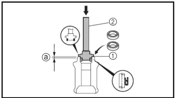

ASSEMBLING THE PROPELLER SHAFT HOUSING
- Install:
- Needle bearing

Needle bearing installation
position ⓐ
24.75 - 25.25 mm
(0.974 - 0.994 in)

Bearing/oil seal attachment .... ①
YB-06196 / 90890-06653
Driver rod ...... ②
YB-06071 / 90890-06604
Bearing/oil seal depth plate .... ③
90890-06603
A For USA and Canada
B For worldwide
- Install:
- Oil seal

Oil seal installation position ⓐ
4.75 - 5.25 mm (0.187 - 0.207 in)

Bearing/oil seal attachment .... ①
YB-06195
Driver rod ...... ②
YB-06071
ASSEMBLING THE REVERSE GEAR
Install:
- Ball bearing

Bearing/oil seal attachment
YB-06200 / 90890-06661
VERIFICATION DE L'EMBRAYAGE A CRABOTS
Vérifier:
- Embrayage à crabots Endommagement/usure → Rem- placer.
VERIFICATION DE ARBRE PORTE-HELICE
Vérifier:
- Arbre porte-hélice Endommagement/usure → Rem- placer.
MONTAGE DU LOGEMENT DE ARBRE PORTE-HELICE
- Installer:
INSTALLING THE PROPELLER SHAFT HOUSING ASSEMBLY
Install:
- Propeller shaft housing assembly
- Claw washer
- Ring nut

Ring nut wrench .... ① YB-34447 / 90890-06511
Ring nut wrench extension ..... ② 90890-06513
NOTE:
To secure the ring nut, bend one tab into the slot in the ring nut and the other tabs toward the propeller shaft housing assembly.
INSTALLATION DU ENSEMBLES LOGEMENT ET ARBRE PORTE- HELICE
Installer:
REMOVING/INSTALLING THE DRIVE SHAFT
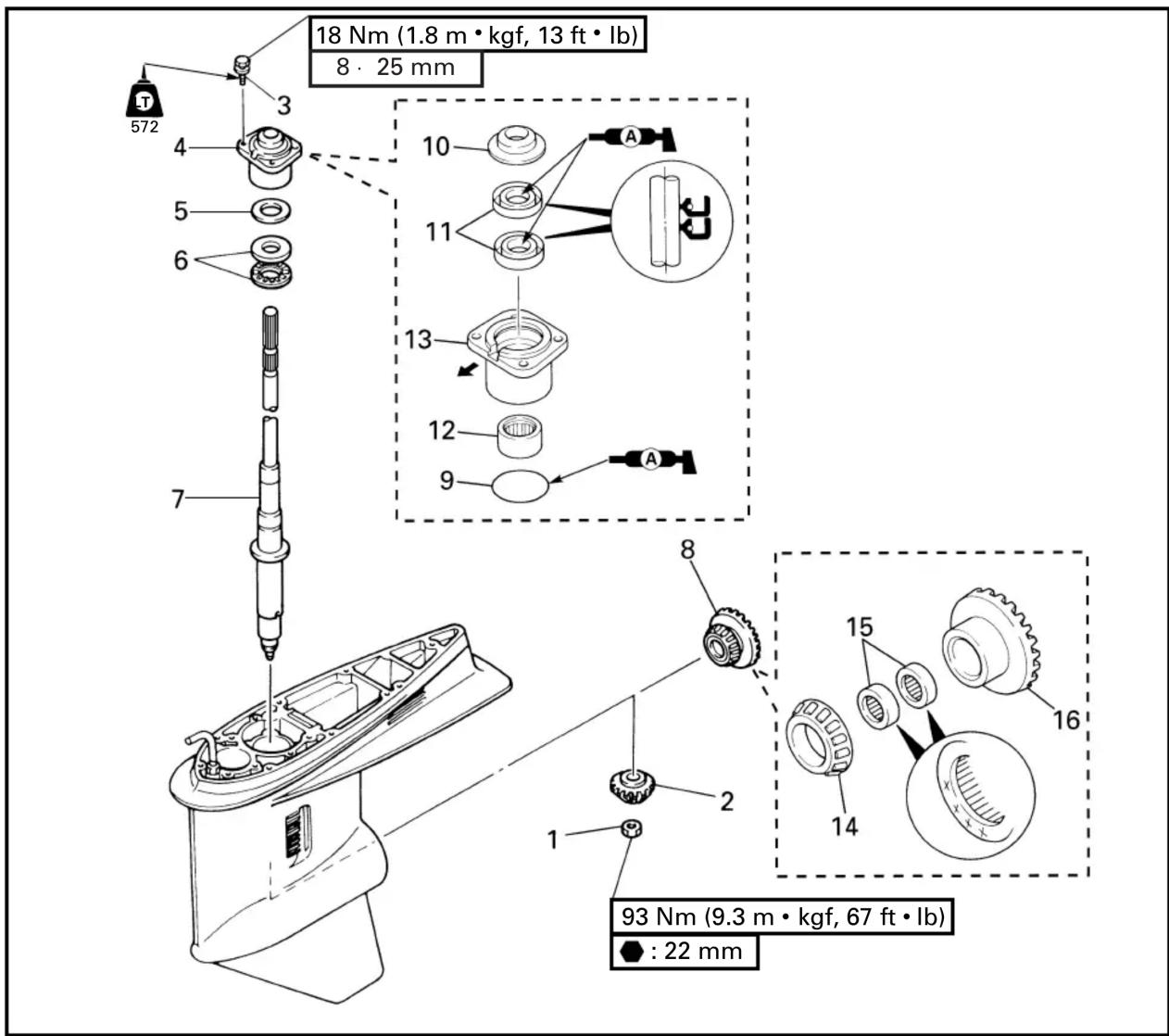
| Order | Job/Part Q'ty Remarks | ||
| Propeller shaft housing assembly | Refer to | “PROPELLER SHAFT HOUSING ASSEMBLY (REGULAR ROTATION MODELS)” on page 6-9. | |
| 1 Nut 1 | |||
| 2 Pinion 1 | |||
| 3 Bolt 4 (with washer) | |||
| 4 Drive shaft housing assembly 1 | |||
| 5 Pinion shim * | |||
| 6 Thrust bearing 1 | |||
| 7 Drive shaft 1 | |||
| Continued on next page. | |||
*: As required
ARBRE D'ENTRAINEMENT (MODELES A ROTATION NORMALE)
DEPOSE/INSTALLATION DE L'ARBRE D'ENTRAINEMENT
| Order | Job/Part Q'ty Remarks | ||
| 8 | Forward gear assembly 1 | ||
| 9 | O-ring 1 | ||
| 10 | Oil seal cover 1 | ||
| 11 | Oil seal 2 | ||
| 12 | Needle bearing 1 | ||
| 13 | Drive shaft housing 1 | ||
| 14 | Tapered roller bearing 1 | Not reusable | |
| 15 | Needle bearing 1 | Not reusable | |
| 16 | Forward gear 1 | For installation, reverse the removal procedure. |


natural_image
Mechanical assembly diagram showing a press or clamping mechanism with no visible text or symbols
REMOVING THE DRIVE SHAFT
Loosen:
- Pinion nut

Drive shaft holder .... ①
YB-06151 / 90890-06519
Pinion nut holder ...... ②
90890-06505
Pinion nut holder attachment. ③
90890-06507
DISASSEMBLING THE DRIVE SHAFT HOUSING ASSEMBLY
Remove:
- Needle bearing

Bearing/oil seal attachment .... ①
YB-06196 / 90890-06610
Driver rod ②
YB-06071 / 90890-06652
DISASSEMBLING THE FORWARD GEAR ASSEMBLY
- Remove:
- Tapered roller bearing

Bearing separator
YB-06219 / 90890-06534
CAUTION:
Do not reuse the bearing, always replace it with a new one.
- Remove:
- Needle bearing

Slide hammer...... ①
YB-06096
Guide plate.... ②
90890-06501
Guide plate stand ...... ③
90890-06538
Bearing puller...... ④
90890-06535
Small universal claws .... ⑤
90890-06536
DEPOSE DE L'ARBRE D'ENTRAINEMENT
Desserrer:
- Ecrou de pignon

Damage/wear → Replace.
CHECKING THE DRIVE SHAFT
Check:
- Drive shaft
Damage/wear → Replace.
CHECKING THE DRIVE SHAFT HOUSING
Check:
- Drive shaft housing
Cracks/damage → Replace.
CHECKING THE BEARINGS
Check:
- Bearings
Pitting/rumbling → Replace.

ASSEMBLING THE FORWARD GEAR ASSEMBLY
- Install:
- Needle bearing

Needle bearing installation
position ⓐ
2.5 - 3.5 mm (0.098 - 0.138 in)
Bearing/oil seal attachment .... ①
YB-06200 / 90890-06612
Driver rod ...... ②
YB-06071 / 90890-06604
VERIFICATION DU PIGNON
Vérifier:
• Dents
Corrosion/grondement → Rem- placer.
MONTAGE DE L'ENS. PIGNON DE MARCHE AVANT
- Installer:
natural_image
Mechanical assembly diagram showing a gear and rotor assembly with a cylindrical component (no text or symbols)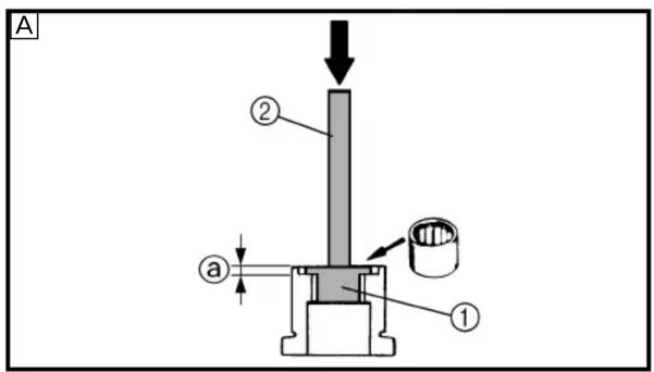
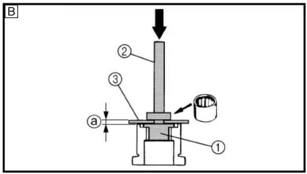
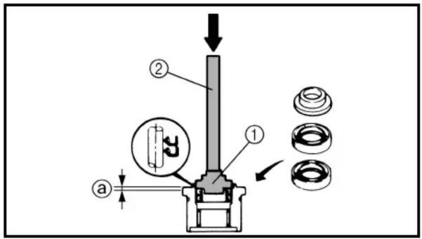
2. Install:
- Tapered roller bearing
| Bearing/oil seal attachment YB-06200 / 90890-06661 |
ASSEMBLING THE DRIVE SHAFT HOUSING ASSEMBLY
1. Install:
- Needle bearing


A For USA and Canada
B For worldwide
2. Install:
- Oil seal


- Installer:
INSTALLING THE DRIVE SHAFT
Tighten:
- Pinion nut

Drive shaft holder ...... ①
YB-06151 / 90890-06519
Pinion nut holder ...... ②
90890-06505
Pinion nut holder attachment. ③
90890-06507

Pinion nut
93 Nm (9.3 m · kgf, 67 ft · lb)
INSTALLATION DE L'ARBRE D'ENTRAINEMENT
Serrer:
- Ecrou de pignon

| Order | Job/Part Q'ty Remarks | ||
| Forward gear Refer to “DRIVE SHAFT (REGULAR ROTATION MODELS)” on page 6-17. | |||
| 1 Drive shaft sleeve 12 Needle bearing 13 Tapered roller bearing outer race 14 Forward gear shim *5 Water seal 16 Plate 1 | |||
| For assembly, reverse the disassembly procedure. | |||
*: As required
ENSEMBLE DU BLOC DE PROPULSION (MODELES A ROTATION NORMALE)
DEMONTAGE/MONTAGE DE L'ENSEMBLE DU BLOC DE PROPULSION

DISASSEMBLING THE LOWER CASE ASSEMBLY
- Remove:
- Needle bearing

Bearing/oil seal attachment .... ① YB-06194 / 90890-06636
Driver rod .... ② YB-06071 / 90890-06605
- Remove:
- Tapered roller bearing outer race

Slide hammer....① YB-06096
Bearing puller.... ② 90890-06523
Large universal claws.... ③ 90890-06532
CHECKING THE DRIVE SHAFT SLEEVE
Check:
- Drive shaft sleeve
Damage/wear → Replace.
CHECKING THE NEEDLE BEARING
Check:
- Needle bearing
Pitting/rumbling → Replace.

ASSEMBLING THE LOWER CASE ASSEMBLY
- Install:
- Tapered roller bearing outer race

Bearing/oil seal attachment .... ① YB-06199 / 90890-06620
Driver rod .... ② YB-06071 / 90890-06605
DEMONTAGE DE L'ENSEMBLE DU BLOC DE PROPULSION
- Déposer:
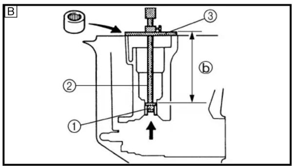
2. Install:
- Needle bearing

Needle bearing installation position ⓐ
10.0 mm (0.39 in)
Needle bearing installation position ⓑ
184.0 mm (7.24 in)

Bearing/oil seal attachment .... ① YB-06194 / 90890-06636
Driver rod .... ② YB-06071 / 90890-06602
Bearing/oil seal depth plate .... ③ YB-06213 / 90890-06603
YB-34474
A For USA and Canada
B For worldwide
- Installer:
REMOVING/INSTALLING THE LOWER UNIT
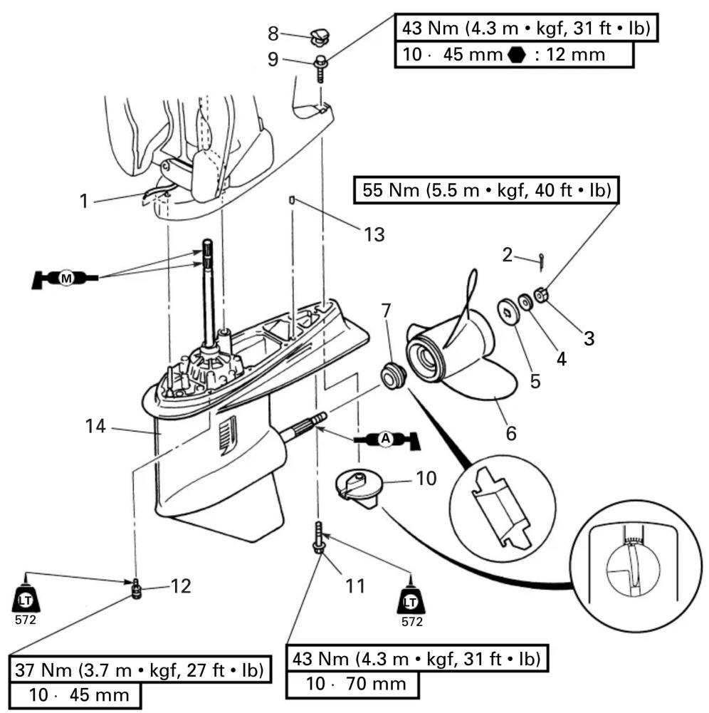
| Order | Job/Part Q'ty Remarks | ||
| 1 | Speedometer hose 1 | ||
| 2 | Cotter pin 1 | ||
| 3 | Propeller nut 1 | ||
| 4 | Washer 1 | ||
| 5 | Washer 1 | ||
| 6 | Propeller 1 | ||
| 7 | Spacer 1 | ||
| Continued on next page. |
BLOC DE PROPULSION (MODELES A CONTRAROTATION)
DEPOSE/INSTALLATION DU BLOC DE PROPULSION
| Order | Job/Part Q'ty Remarks | ||
| 8 Grommet 19 Bolt 110 Trim tab 111 Bolt 1 (with washer)12 Bolt 6 (with washer)13 Dowel pin 214 Lower unit 1 | For installation, reverse the removal procedure. |
natural_image
Line drawing of a hand operating a propeller with a wooden handle (no text or symbols)REMOVING THE PROPELLER
Remove:
- Propeller
WARNING
Do not hold the propeller with your hands when removing or installing it. Be sure to remove the battery leads from the batteries and the lanyard engine stop switch. Put a block of wood between the cavitation plate and propeller to keep the propeller from turning.
CHECKING THE PROPELLER
Check:
- Blades
- Splines
Cracks/damage/wear → Replace.

natural_image
Line drawing of a hand operating a propeller with a tool, no text or symbols presentINSTALLING THE PROPELLER
Install:
- Propeller
WARNING
Do not hold the propeller with your hands when removing or installing it. Be sure to remove the battery leads from the batteries and the lanyard engine stop switch. Put a block of wood between the cavitation plate and propeller to keep the propeller from turning.
NOTE:
If the groove in the propeller nut is not aligned with the cotter pin hole, tighten the nut further until they are aligned.
DEPOSE DE L'HELICE
Déposer:
• Hélice
AVERTISSEMENT
| Order | Job/Part Q'ty Remarks | ||
| Lower unit Refer to “LOWER UNIT (COUNTER ROTATION MODELS)” on page 6-26. | |||
| 1 Bolt 4 | |||
| 2 Impeller housing 1 | |||
| 3 Impeller housing cup 1 | |||
| 4 O-ring 1 | |||
| 5 O-ring 1 | |||
| 6 Grommet 1 | |||
| 7 Spacer 1 | |||
| 8 Collar 1 | |||
| Continued on next page. | |||
POMPE A EAU (MODELES A CONTRAROTATION)
DEPOSE/INSTALLATION DE LA POMPE A EAU
Cracks/damage → Replace.
CHECKING THE IMPELLER AND IMPELLER HOUSING CUP
Check:
- Impeller
- Impeller housing cup
Cracks/damage → Replace any defective parts.
CHECKING THE WOODRUFF KEY
Check:
- Woodruff key
Damage/wear → Replace.


INSTALLING THE IMPELLER AND IMPELLER HOUSING
-
Install:
-
Washers ①
- Wave washer ②
- Spacer ③
- Collar ④
NOTE:
- The collar and spacer should fit together firmly.
-
While pulling the drive shaft up, install the collar with some appropriate tool @ that fits over the drive shaft as shown.
-
Install:
-
O-ring ①
- Impeller housing cup ②
- Impeller housing ③
- O-ring ④
NOTE:
- When installing the impeller housing cup, align its projection with the hole in the impeller housing.
- When installing the water pump housing, turn the drive shaft clockwise.
LOWR

VERIFICATION DU LOGEMENT DE ROUE HELICE
Vérifier:
- Logement de roue hélice Fissures/endommagement → Remplacer.
VERIFICATION DE LA ROUE HELICE ET DE LA COUPELLE DU CARTER DE ROUE HELICE
Vérifier:
- Roue hélice
SHIFT ROD ASSEMBLY (COUNTER ROTATION MODELS) REMOVING/INSTALLING THE SHIFT ROD ASSEMBLY

| Order | Job/Part Q'ty Remarks | ||
| Impeller plate Refer to “WATER PUMP (COUNTER ROTATION MODELS)” on page 6-29. | |||
| 1 Bolt 3 (with washer) | |||
| 2 Shift rod assembly 1 | |||
| 3 Oil seal housing 1 | |||
| 4 Oil seal 1 | |||
| 5 O-ring 1 3.1 · 49.4 mm | |||
| 6 Spring 1 | |||
| 7 Shift rod 1 | |||
| 8 Circlip 1 | |||
| For installation, reverse the removal procedure. | |||
ENSEMBLE DE TIGE DE SELECTION (MODELES A CONTRAROTATION)
DEPOSE/INSTALLATION DE L'ENSEMBLE DE TIGE DE SELECTION
REMOVING THE SHIFT ROD ASSEMBLY
Remove:
- Shift rod assembly
NOTE: ____
Remove the shift rod assembly when the shift rod is in the neutral position.
DEPOSE DE L'ENSEMBLE DE TIGE DE SELECTION
Déposer:
PROPELLER SHAFT HOUSING ASSEMBLY
(COUNTER ROTATION MODELS)
REMOVING/INSTALLING THE PROPELLER SHAFT HOUSING ASSEMBLY

| Order | Job/Part Q'ty Remarks | ||
| Gear oil Refer to “CHANGING AND CHECKING Shift rod assembly Refer to “SHIFT ROD ASSEMBLY (COUNTER ROTATION MODELS)” on page 6-32. | |||
| 1 Ring nut 1 | |||
| 2 Claw washer 1 | |||
| 3 Propeller shaft housing assembly 1 | |||
| Continued on next page. | |||
ENSEMBLES LOGEMENT ET ARBRE PORTE-HELICE
(MODELES A CONTRAROTATION)
DEPOSE/INSTALLATION DU ENSEMBLES LOGEMENT ET ARBRE PORTE-HELICE
| Order | Job/Part Q'ty Remarks | ||
| 4 | Straight key 1 | ||
| 5 | Front propeller shaft assembly 1 | ||
| 6 | Thrust washer 1 | ||
| 7 | Forward gear shim * | For installation, reverse the removal procedure. |
*: As required
| Order | Job/Part Q'ty Remarks | ||
| 1 | O-ring 1 | ||
| 2 | Forward gear assembly 1 | ||
| 3 | Rear propeller shaft 1 | ||
| 4 | Thrust bearing 1 | ||
| 5 | Propeller shaft shim * | ||
| 6 | Needle bearing 1 | ||
| 7 | Oil seal 2 | ||
| Continued on next page. |
*: As required
DEMONTAGE/MONTAGE DU ENSEMBLES LOGEMENT ET ARBRE PORTE-HELICE
| Order | Job/Part Q'ty Remarks | ||
| 1 | Spring 1 | ||
| 2 | Pin 1 | ||
| 3 | Dog clutch 1 | ||
| 4 | Shift rod joint 1 | ||
| 5 | Shift rod joint slider 1 | ||
| 6 | Ball 2 | ||
| 7 | Ball 2 | ||
| 8 | Spring 1 | ||
| 9 | Ball 2 | ||
| 10 | Front propeller shaft 1 | ||
| For assembly, reverse the disassembly procedure. |
DEMONTAGE/MONTAGE DE L'ARBRE PORTE-HELICE AVANT
REMOVING THE PROPELLER SHAFT HOUSING ASSEMBLY
- Straighten:
- Claw washer tabs
- Remove:
- Ring nut
- Claw washer

Ring nut wrench .... ① YB-34447 / 90890-06511
Ring nut wrench extension ..... ② 90890-06513
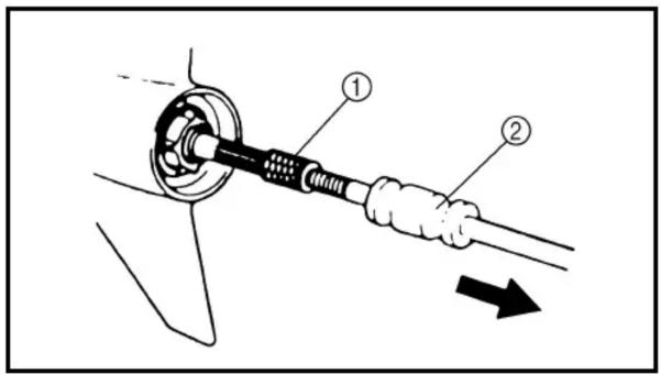
- Remove:
- Propeller shaft housing assembly

Slide hammer attachment...... ① YB-06335 / 90890-06514
Slide hammer.... ② YB-06096 / 90890-06531

REMOVING THE FORWARD GEAR ASSEMBLY
Remove:
- Rear propeller shaft
- Forward gear assembly

Propeller shaft housing puller. ① YB-06207 / 90890-06502
Universal puller YB-06117
Guide plate.... ② 90890-06501
Center bolt ③ 90890-06504
DEPOSE DU ENSEMBLES LOGEMENT ET ARBRE PORTE- HELICE
- Redresser:
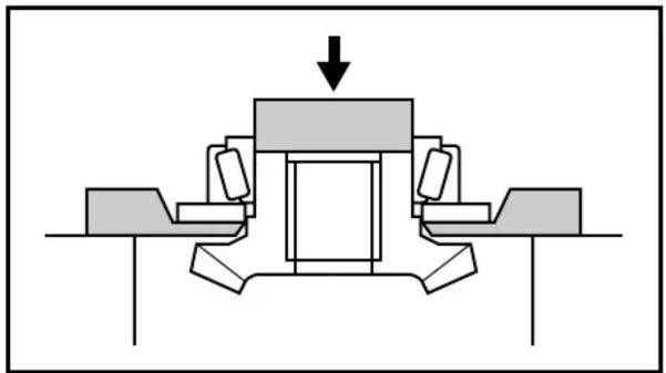
natural_image
Pure mechanical diagram showing a central component with two side supports and an arrow indicating downward motion (no text or symbols)DISASSEMBLING THE PROPELLER SHAFT HOUSING ASSEMBLY
- Remove:
- Needle bearing

Slide hammer.... ① YB-06096
Guide plate.... ② 90890-06501
Guide plate stand ..... ③ 90890-06538
Bearing puller.... ④ 90890-06535
Small universal claws .... ⑤ 90890-06536
A For USA and Canada
B For worldwide
- Remove:
- Oil seal
- Needle bearing

Bearing/oil seal attachment .... ① YB-06196 / 90890-06653
Driver rod .... ② YB-06071 / 90890-06652
DISASSEMBLING THE FORWARD GEAR ASSEMBLY
- Remove:
- Tapered roller bearing

Bearing separator YB-06219 / 90890-06534
CAUTION:
Do not reuse the bearing, always replace it with a new one.
DEMONTAGE DU ENSEMBLES LOGEMENT ET ARBRE PORTE- HELICE
- Déposer:
A For USA and Canada
B For worldwide
CHECKING THE FORWARD GEAR
Check:
- Teeth
- Dogs
Damage/wear → Replace.
CHECKING THE BEARING
Check:
- Bearing
Pitting/rumbling → Replace.
CHECKING THE PROPELLER SHAFT HOUSING
Check:
- Propeller shaft housing
Cracks/damage → Replace.
CHECKING THE DOG CLUTCH
Check:
- Dog clutch
Damage/wear → Replace.
CHECKING THE PROPELLER SHAFTS
Check:
- Propeller shafts
Damage/wear → Replace.
- Déposer:
Corrosion/grondement → Rem- placer.
VERIFICATION DU LOGEMENT DE L'ARBRE PORTE-HELICE
Vérifier:
- Logement d'arbre porte-hélice Fissures/endommagement → Remplacer.
VERIFICATION DE L'EMBRAYAGE A CRABOTS
Vérifier:


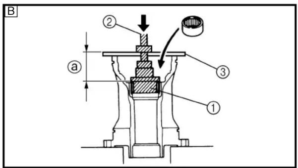
ASSEMBLING THE FORWARD GEAR
Install:
- Needle bearing


A For USA and Canada
B For worldwide
ASSEMBLING THE PROPELLER SHAFT HOUSING ASSEMBLY
- Install:
- Needle bearing


A For USA and Canada
B For worldwide
MONTAGE DU PIGNON DE MARCHE AVANT
Installer:

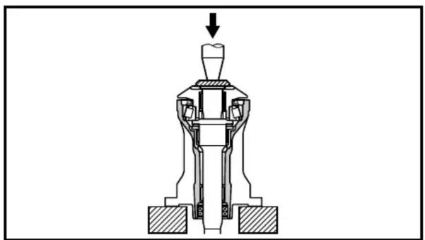
natural_image
Cross-sectional diagram of a mechanical assembly with no visible text or symbols2. Install:
- Needle bearing

Needle bearing installation
position ⓐ
24.75 - 25.25 mm
(0.974 - 0.994 in)
Bearing/oil seal attachment .... ①
YB-06196 / 90890-06610
Driver rod ...... ②
YB-06071 / 90890-06604
Bearing/oil seal depth plate .... ③
90890-06603
A For USA and Canada
B For worldwide
3. Install:
- Oil seal

Oil seal installation position ⓐ
4.75 - 5.25 mm (0.187 - 0.207 in)

Bearing/oil seal attachment .... ①
YB-06195
Driver rod ...... ②
YB-06071
INSTALLING THE FORWARD GEAR ASSEMBLY
1. Install:
- Rear propeller shaft
- Tapered roller bearing

Bearing/oil seal attachment .... ①
YB-06430 / 90890-06656
Driver rod ...... ②
YB-06071 / 90890-06606
2. Install:
- Thrust washer
-
Forward gear
-
Installer:
INSTALLING THE PROPELLER SHAFT HOUSING ASSEMBLY
Install:
- Propeller shaft housing assembly
- Claw washer
- Ring nut

Ring nut wrench .... ① YB-34447 / 90890-06511
Ring nut wrench extension ..... ② 90890-06513
NOTE:
To secure the ring nut, bend one tab into the slot in the ring nut and the other tabs toward the propeller shaft housing assembly.
INSTALLATION DU ENSEMBLES LOGEMENT ET ARBRE PORTE- HELICE
Installer:
REMOVING/INSTALLING THE DRIVE SHAFT

| Order | Job/Part Q'ty Remarks | ||
| Propeller shaft housing assembly | Refer to | “PROPELLER SHAFT HOUSING ASSEMBLY (COUNTER ROTATION MODELS)” on page 6-34. | |
| 1 Nut 1 | |||
| 2 Pinion 1 | |||
| 3 Bolt 4 (with washer) | |||
| 4 Drive shaft housing assembly 1 | |||
| 5 Pinion shim * | |||
| 6 Thrust bearing 1 | |||
| 7 Drive shaft 1 | |||
| Continued on next page. | |||
*: As required
ARBRE D'ENTRAINEMENT (MODELES A CONTRAROTATION)
DEPOSE/INSTALLATION DE L'ARBRE D'ENTRAINEMENT
| Order | Job/Part Q'ty Remarks | ||
| 8 | Reverse gear assembly 1 | ||
| 9 | Thrust bearing 1 | ||
| 10 | O-ring 1 | ||
| 11 | Oil seal cover 1 | ||
| 12 | Oil seal 2 | ||
| 13 | Needle bearing 1 | ||
| 14 | Drive shaft housing 1 | ||
| 15 | Needle bearing 1 | ||
| 16 | Reverse gear 1 | ||
| For installation, reverse the removal procedure. |
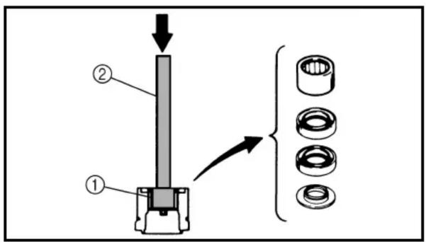

REMOVING THE DRIVE SHAFT
Loosen:
- Pinion nut

Drive shaft holder .... ① YB-06151 / 90890-06519
Pinion nut holder ② 90890-06505
Pinion nut holder attachment. ③ 90890-06507
DISASSEMBLING THE DRIVE SHAFT HOUSING ASSEMBLY
Remove:
- Needle bearing

Bearing/oil seal attachment .... ① YB-06196 / 90890-06610
Driver rod .... ② YB-06071 / 90890-06652
DISASSEMBLING THE REVERSE GEAR
Remove:
- Needle bearing

Slide hammer.... ① YB-06096
Guide plate.... ② 90890-06501
Guide plate stand ..... ③ 90890-06538
Bearing puller.... ④ 90890-06535
Small universal claws .... ⑤ 90890-06536
CHECKING THE PINION
Check:
- Teeth
Damage/wear → Replace.
CHECKING THE DRIVE SHAFT
Check:
- Drive shaft
Damage/wear → Replace.
DEPOSE DE L'ARBRE D'ENTRAINEMENT
Desserrer:
- Ecrou de pignon

- Drive shaft housing
Cracks/damage → Replace.
CHECKING THE BEARINGS
Check:
- Bearings
Pitting/rumbling → Replace.
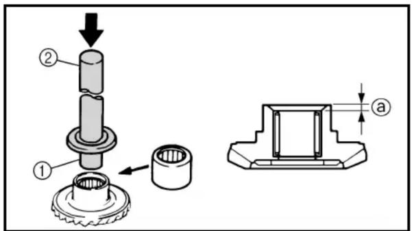
ASSEMBLING THE REVERSE GEAR ASSEMBLY
Install:
- Needle bearing

Needle bearing installation position ⓐ 2.5 - 3.5 mm (0.098 - 0.138 in)

Bearing/oil seal attachment .... ① YB-06200 / 90890-06612 Driver rod .... ② YB-06071 / 90890-06604

ASSEMBLING THE DRIVE SHAFT HOUSING ASSEMBLY
- Install:
- Needle bearing

Position ⓐ 5.75 - 6.25 mm (0.226 - 0.246 in)

Bearing/oil seal attachment .... ① YB-06196 / 90890-06610 Driver rod .... ② YB-06071 / 90890-06604 Bearing/oil seal depth plate .... ③ 90890-06603
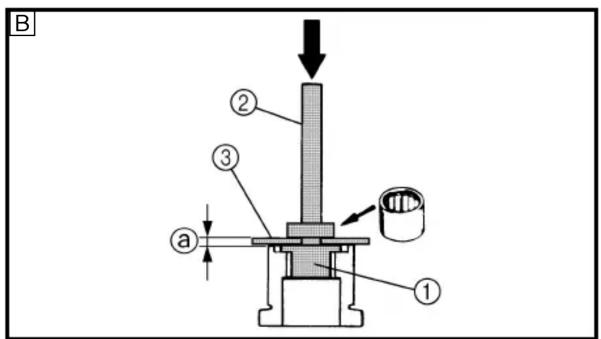
A For USA and Canada
B For worldwide
VERIFICATION DU LOGEMENT DE ROULEMENT D'ARBRE D'ENTRAINEMENT
Vérifier:
- Install:
- Oil seal

Oil seal installation position ⓐ 0.25 - 0.75 mm (0.010 - 0.030 in)

Bearing/oil seal attachment .... ① YB-06195 Driver rod .... ② YB-06071
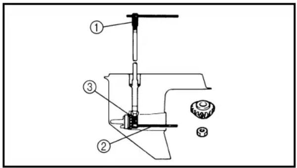
INSTALLING THE DRIVE SHAFT
Tighten:
- Pinion nut

Drive shaft holder ..... ① YB-06151 / 90890-06519 Pinion nut holder ..... ② 90890-06505 Pinion nut holder attachment . ③ 90890-06507

Pinion nut 93 Nm (9.3 m · kgf, 67 ft · lb)
- Installer:
| Order | Job/Part Q'ty Remarks | ||
| Reverse gear Refer to “DRIVE SHAFT (COUNTER ROTATION MODELS)” on page 6-45. | |||
| 1 Drive shaft sleeve 12 Needle bearing 13 Bearing retainer 14 Needle bearing 15 Reverse gear shim *6 Water seal 17 Plate 1 | |||
| For assembly, reverse the disassembly procedure. | |||
*: As required
ENSEMBLE DU BLOC DE PROPULSION (MODELES A CONTRAROTATION)
DEMONTAGE/MONTAGE DE L'ENSEMBLE DU BLOC DE PROPULSION


DISASSEMBLING THE LOWER CASE ASSEMBLY
- Remove:
- Needle bearing

Bearing/oil seal attachment .... ① YB-06194 / 90890-06636
Driver rod .... ② YB-06071 / 90890-06605
- Remove:
- Roller bearing

Slide hammer....① YB-06096
Bearing puller.... ② 90890-06523
Large universal claws.... ③ 90890-06532
- Remove:
- Needle bearing

Bearing/oil seal attachment .... ① YB-06376 / 90890-06607
Driver rod .... ② YB-06071 / 90890-06652
CHECKING THE DRIVE SHAFT SLEEVE
Check:
- Drive shaft sleeve
Damage/wear → Replace.
CHECKING THE NEEDLE BEARING
Check:
- Needle bearing
Pitting/rumbling → Replace.
DEMONTAGE DE L'ENSEMBLE DU BLOC DE PROPULSION
- Déposer:
ASSEMBLING THE LOWER CASE ASSEMBLY
- Install:
- Needle bearing

Needle bearing installation position ⓐ 0.75 - 1.25 mm (0.030 - 0.049 in)

Bearing/oil seal attachment .... ① YB-06376 / 90890-06607 Driver rod .... ② YB-06071 / 90890-06652

- Install:
- Bearing retainer

Bearing/oil seal attachment .... ① YB-06377 / 90890-06630 Driver rod .... ② YB-06071 / 90890-06605

- Install:
- Needle bearing

Needle bearing installation position ⓐ 184.0 mm (7.24 in)

Bearing/oil seal attachment .... ① YB-06194 / 90890-06636 Driver rod .... ② YB-06071 / 90890-06602 Bearing/oil seal depth plate .... ③ YB-34474 / 90890-06603
MONTAGE DE L'ENSEMBLE DU BLOC DE PROPULSION
- Installer:
- There is no need to select shims when reassembling with the original case and inner parts.
- Shim calculations are required when reassembling with the original inner parts and a new case (the difference between the original inner parts and the new case).
• Measurements and adjustments are required when replacing the inner part(s).

SELECTION DES CALES (MODELES A ROTATION NORMALE) (POUR LES E.-U. ET LE CANADA)
N.B.:
Find the shim thickness (T3) by selecting shims until the specified value (M0) is obtained with the special tool.
1. Measure:
- Specified measurement (M)
Out of specified value (M0) → Adjust.

Specified value (M0) = 1.00 + P/100 mm
Measuring steps
(1) Calculate the specified value (M0).
NOTE:
"P" is the deviation of the lower case dimension from standard. It is stamped on the trim tab mounting surface of the lower case in 0.01-mm units. If the "P" mark is missing or unreadable, assume a "P" value of "0", and check the backlash when the unit is assembled.
Example:
If "P" is "+5", then
M0 = 1.00 + (+5)/100 mm
$$ = 1. 0 0 + 0. 0 5 \mathrm{mm} $$
$$ = 1. 0 5 \mathrm{mm} $$
If "P" is "-3", then
M0 = 1.00 + (-3)/100 mm
$$ = 1. 0 0 - 0. 0 3 \mathrm{mm} $$
$$ = 0. 9 7 \mathrm{mm} $$
SELECTION DES CALES DE PIGNON
N.B.:
(2) Install the pinion height gauge, drive shaft, thrust bearing ①, and shim(s) ②.
| Pinion height gauge YB-34432-6, -11 |
NOTE: ____
If the original shim(s) is unavailable, start with a 0.50-mm shim.
(3) Install the pinion and pinion nut.
| Pinion nut 93 Nm (9.3 m • kgf, 67 ft • lb) |

(4) Measure the specified measurement (M).
NOTE:
- Measure the clearance between the pinion height gauge and the lower surface of the pinion as shown.
- Perform the same measurement at three points on the pinion.
• Find the average of the measurements (M).
2. Adjust:
- Shim thickness (T3)
Remove or add shim(s).
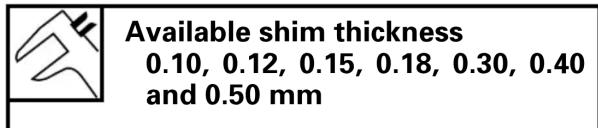
NOTE: ____
(M0) - (M) should be as close to "0" as possible.


SELECTING THE FORWARD GEAR SHIMS
NOTE:
Find the shim thickness (T1) by selecting shims until the specified value (M0) is obtained with the special tool.
1. Measure:
- Specified measurement (M)
Out of specified value (M0) → Adjust.

Specified value (M0) = 1.80 + F/100 mm
Measuring steps
(1) Calculate the specified value (M0).
NOTE:
“F” is the deviation of the lower case dimension from standard. It is stamped on the trim tab mounting surface of the lower case in 0.01-mm units. If the “F” mark is missing or unreadable, assume an “F” value of “0”, and check the backlash when the unit is assembled.
Example:
If "F" is "+5", then
M0 = 1.80 + (+5)/100 mm
$$ = 1. 8 0 + 0. 0 5 \mathrm{mm} $$
$$ = 1. 8 5 \mathrm{mm} $$
If "F" is "-3", then
M0 = 1.80 + (-3)/100 mm
$$ = 1. 8 0 - 0. 0 3 \mathrm{mm} $$
$$ = 1. 7 7 \mathrm{mm} $$
SELECTION DES CALES DU PIGNON DE MARCHE AVANT
N.B.:
M0 = 1,80 + (+5)/100 mm
$$ = 1, 8 0 + 0, 0 5 \mathrm{mm} $$
$$ = 1, 8 5 \mathrm{mm} $$
(2) Install the shimming gauge, bearing ①, and shim(s) ②.

Shimming gauge YB-34446-1, -3, -5, -7
NOTE: ____
If the original shim(s) is unavailable, start with a 0.50-mm shim.
(3) Measure the specified measurement (M).
- Adjust:
- Shim thickness (T1) Remove or add shim(s).

Available shim thickness 0.10, 0.12, 0.15, 0.18, 0.30, 0.40 and 0.50 mm
NOTE:
(M0) - (M) should be as close to "0" as possible.

Find the shim thickness (T2) by selecting shims until the specified value (M0) is obtained with the special tool.
1. Measure:
- Specified measurement (M)
Out of specified value (M0) → Adjust.

Specified value (M0) = 1.80 - R/100 mm
Measuring steps
(1) Calculate the specified value (M0).
NOTE:
“R” is the deviation of the lower case dimension from standard. It is stamped on the trim tab mounting surface of the lower case in 0.01-mm units. If the “R” mark is missing or unreadable, assume an “R” value of “0”, and check the backlash when the unit is assembled.
Example:
If "R" is "+5", then
M0 = 1.80 - (+5)/100 mm
$$ = 1. 8 0 - 0. 0 5 \mathrm{mm} $$
$$ = 1. 7 5 \mathrm{mm} $$
If "R" is "-3", then
M0 = 1.80 - (-3)/100 mm
$$ = 1. 8 0 + 0. 0 3 \mathrm{mm} $$
$$ = 1. 8 3 \mathrm{mm} $$
LOWR

SELECTION DES CALES DU PIGNON DE MARCHE ARRIERE
N.B.:
(2) Install the shimming gauge, bearing, thrust washer, reverse gear, and shim(s).

Shimming gauge YB-34468-2
NOTE: ____
- If the original shim(s) is unavailable, start with a 0.50-mm shim.
- Turn the reverse gear assembly a few times until the gear and bearing are horizontal.
(3) Measure the specified measurement (M).
-
Adjust:
-
Shim thickness (T2)
Remove or add shim(s).

Available shim thickness 0.10, 0.12, 0.15, 0.18, 0.30, 0.40 and 0.50 mm
NOTE:
(M0) - (M) should be as close to "0" as possible.
- There is no need to select shims when reassembling with the original case and inner parts.
- Shim calculations are required when reassembling with the original inner parts and a new case (the difference between the original inner parts and the new case).
• Measurements and adjustments are required when replacing the inner part(s).
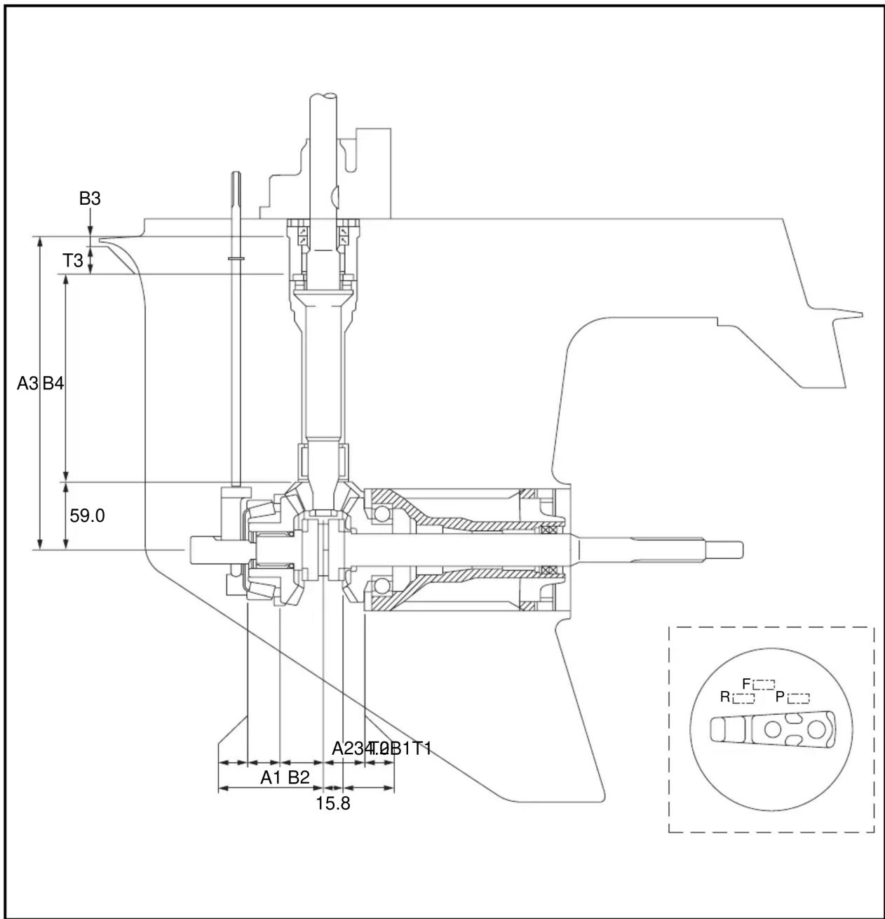
SELECTION DES CALES (MODELES A ROTATION NORMALE) (POUR LE RESTE DU MONDE)
N.B.:
Select the shim thickness (T3) by using the specified measurement(s) and the calculation formula.
Select:
- Shim thickness (T3)
Selecting steps
(1) Measure (M3).
| Digital caliper 90890-06704 |
NOTE: ____
Install the bearing housing ①, thrust bearing ②, and washer ③.
(2) Install the pinion and pinion nut.
| Pinion nut 93 Nm (9.3 m • kgf, 67 ft • lb) |
(3) Install the pinion height gauge.
| Pinion height gauge 90890-06702 |
NOTE: ____
After the wing nuts contact the fixing plate, tighten them another 1/4 of a turn.
(4) Measure (M4).
| Digital caliper 90890-06704 |
NOTE: ____
- Measure the clearance between the pinion height gauge and the pinion, as shown.
- Perform the same measurement at three points on the pinion.
- Find the average of the measurements (M4).
SELECTION DES CALES DE PIGNON
N.B.:
Pinion shim thickness (T3) = 62.5 + P/100 - M3 - M4
NOTE:
"P" is the deviation of the lower case dimension from standard. It is stamped on the trim tab mounting surface of the lower case in 0.01-mm units. If the "P" mark is missing or unreadable, assume a "P" value of "0", and check the backlash when the unit is assembled.
Example:
If M3 is “46.85 mm”, M4 is “15.12 mm” and P is “-5”, then
T3 = 62.5 + (-5)/100 - 46.85 - 15.12 mm
= 62.5 - 0.05 - 46.85 - 15.12 mm
= 0.48 mm
(6) Select the pinion shim(s) (T3).
| Calculated numeral at 1/100th place | Rounded numeral | |
| More than or less | ||
| 0.00 0.02 | 0.00 | |
| 0.02 0.05 | 0.02 | |
| 0.05 0.08 | 0.05 | |
| 0.08 0.10 | 0.08 | |
 | Available shim thickness0.10, 0.12, 0.15, 0.18, 0.30, 0.40 and 0.50 mm | |
SELECTING THE FORWARD GEAR SHIMS
NOTE:
Select the shim thickness (T1) by using the specified measurement(s) and the calculation formula.
Select:
- Shim thickness (T1)
Selecting steps
(1) Measure (M1).

Shimming plate ..... ①
90890-06701
Digital caliper ②
90890-06704
NOTE:
- Turn the roller bearing outer race two or three times so the rollers seat. Then, measure the height of the bearing, as shown.
- Perform the same measurement at three points on the roller bearing outer race.
- Find the average of the measurements (M1).

(2) Calculate the forward gear shim thickness (T1).

Forward gear shim thickness (T1) (T1) = 24.6 + F/100 - M1
NOTE:
“F” is the deviation of the lower case dimension from standard. It is stamped on the trim tab mounting surface of the lower case in 0.01-mm units. If the “F” mark is missing or unreadable, assume an “F” value of “0”, and check the backlash when the unit is assembled.
SELECTION DES CALES DU PIGNON DE MARCHE AVANT
N.B.:
If M1 is "24.10 mm" and F is "+5", then
T1 = 24.6 + (+5)/100 - 24.10 mm
= 24.6 + 0.05 - 24.10 mm
= 0.55 mm
(3) Select the forward gear shim(s) (T1).
| Calculated numeral at 1/100th place | Rounded numeral | |
| More than or less | ||
| 0.00 0.02 | 0.00 | |
| 0.02 0.05 | 0.02 | |
| 0.05 0.08 | 0.05 | |
| 0.08 0.10 | 0.08 | |
 | Available shim thickness0.10, 0.12, 0.15, 0.18, 0.30, 0.40 and 0.50 mm | |
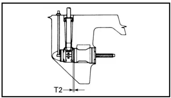
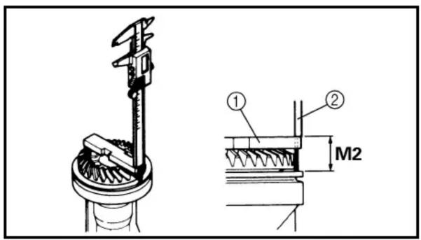
SELECTING THE REVERSE GEAR SHIM
NOTE:
Select the shim thickness (T2) by using the specified measurement(s) and the calculation formula.
Select:
- Shim thickness (T2)
Selecting steps
(1) Measure (M2).
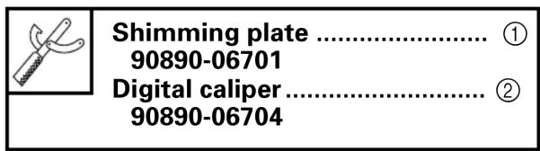
NOTE:
- Measure the height of the gear as shown.
- Perform the same measurement at three points on the gear.
- Find the average of the measurements (M2).
Exemple:
(2) Calculate the reverse gear shim thickness (T2).

Reverse gear shim thickness
(T2) = M2 - 27.4 - R/100
NOTE:
“R” is the deviation of the lower case dimension from standard. It is stamped on the trim tab mounting surface of the lower case in 0.01-mm units. If the “R” mark is missing or unreadable, assume a “R” value of “0”, and check the backlash when the unit is assembled.

Example:
If M2 is "27.95 mm", R is "+2", then
T2 = 27.95 - 27.4 - (+2)/100 mm
= 27.95 - 27.4 - 0.02 mm
= 0.53 mm
(3) Select the reverse gear shim(s) (T2).
| Calculated numeral at 1/100th place | Rounded numeral | |
| More than or less | ||
| 0.00 0.02 | 0.02 | |
| 0.02 0.05 | 0.05 | |
| 0.05 0.08 | 0.08 | |
| 0.08 0.10 | 0.10 | |
 | Available shim thickness0.10, 0.12, 0.15, 0.18, 0.30, 0.40 and 0.50 mm | |
- Do not install the water pump components when measuring the backlash.
- Measure both the forward and reverse gear backlashes.
- If both the forward and reverse gear back-lashes are larger than specification, the pinion may be too high.
- If both the forward and reverse gear back-lashes are smaller than specification, the pinion may be too low.
MEASURING THE FORWARD GEAR BACKLASH
1. Measure:
- Forward gear backlash Out of specification → Adjust.

Forward gear backlash 0.20 - 0.31 mm (0.008 - 0.012 in)
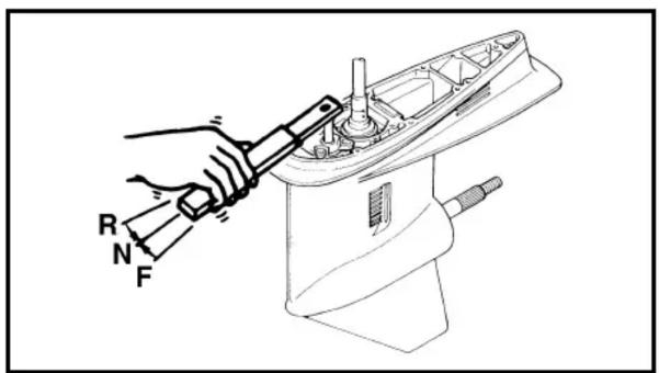
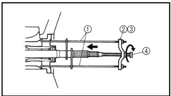
Measuring steps
(1) Set the shift rod into the neutral position.

Shift rod wrench YB-06052 / 90890-06052
(2) Install the propeller shaft housing puller so it pushes against the propeller shaft.

Propeller shaft housing puller. ① YB-06207 / 90890-06502
Universal puller.... ② YB-06117 / 90890-06521
Guide plate.... ③ 90890-06501
Center bolt ④ 90890-06504

Center bolt 10 Nm (1.0 m · kgf, 7.2 ft · lb)
JEU DE RETOUR (MODELES A ROTATION NORMALE)
N.B.:
(3) Install the backlash indicator onto the drive shaft (on the 22.4 mm (0.88 in) diameter portion of the drive shaft).
| Backlash indicator ........ ⑤ YB-06265 / 90890-06706 |
(4) Install the dial gauge onto the lower unit and have the dial gauge plunger contact the mark on the backlash indicator.

(5) Set the lower unit upside down.
(6) Slowly turn the drive shaft clockwise and counterclockwise. When the drive shaft stops in each direction, measure the backlash.
2. Adjust:
- Forward gear shim Remove or add shim(s).
| Forward gear backlash | Shim thickness | |
| Less than 0.20 mm (0.008 in) | To be decreased by (0.26 – M) · 0.58 | |
| More than 0.31 mm (0.012 in) | To be increased by (M – 0.26) · 0.58 | |
M: Measurement
MEASURING THE REVERSE GEAR BACKLASH
1. Measure:
- Reverse gear backlash Out of specification → Adjust.
| Reverse gear backlash 0.50 - 0.73 mm (0.020 - 0.029 in) |
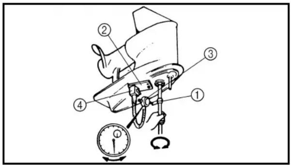
Measuring steps
(1) Set the shift rod into the neutral position.

Shift rod wrench YB-06052 / 90890-06052
(2) Load the reverse gear by installing the propeller without the spacer ① and then tighten the propeller nut.

Propeller nut 10 Nm (1.0 m · kgf, 7.2 ft · lb)
(3) Install the backlash indicator onto the drive shaft (on the 22.4 mm (0.88 in) diameter portion of the drive shaft).

Backlash indicator .... ① YB-06265 / 90890-06706
(4) Install the dial gauge onto the lower unit and have the dial gauge plunger contact the mark on the backlash indicator.

Magnetic-base plate....② YB-07003 / 90890-07003 Dial gauge set....③ YU-03097 / 90890-01252 Magnetic base....④ YU-34481 / 90890-06705
(5) Set the lower unit upside down.
(6) Slowly turn the drive shaft clockwise and counterclockwise. When the drive shaft stops in each direction, measure the backlash.
LOWR

JEU DE RETOUR (MODELES A ROTATION NORMALE) RÜCKSCHLAG (MODELLE MIT NORMALDREHRICHTUNG) CONTRAGOLPE (MODELOS DE ROTACIÓN REGULAR)
Etapes de la mesure
| Reverse gear backlash | Shim thickness | |
| Less than 0.50 mm (0.020 in) | To be increased by (0.62 – M) · 0.58 | |
| More than 0.73 mm (0.029 in) | To be decreased by (M – 0.62) · 0.58 | |
M: Measurement
2. Régler:
SHIMMING (COUNTER ROTATION MODELS) (FOR USA AND CANADA)
NOTE:
- There is no need to select shims when reassembling with the original case and inner parts.
- Shim calculations are required when reassembling with the original inner parts and a new case (the difference between the original inner parts and the new case).
• Measurements and adjustments are required when replacing the inner part(s).
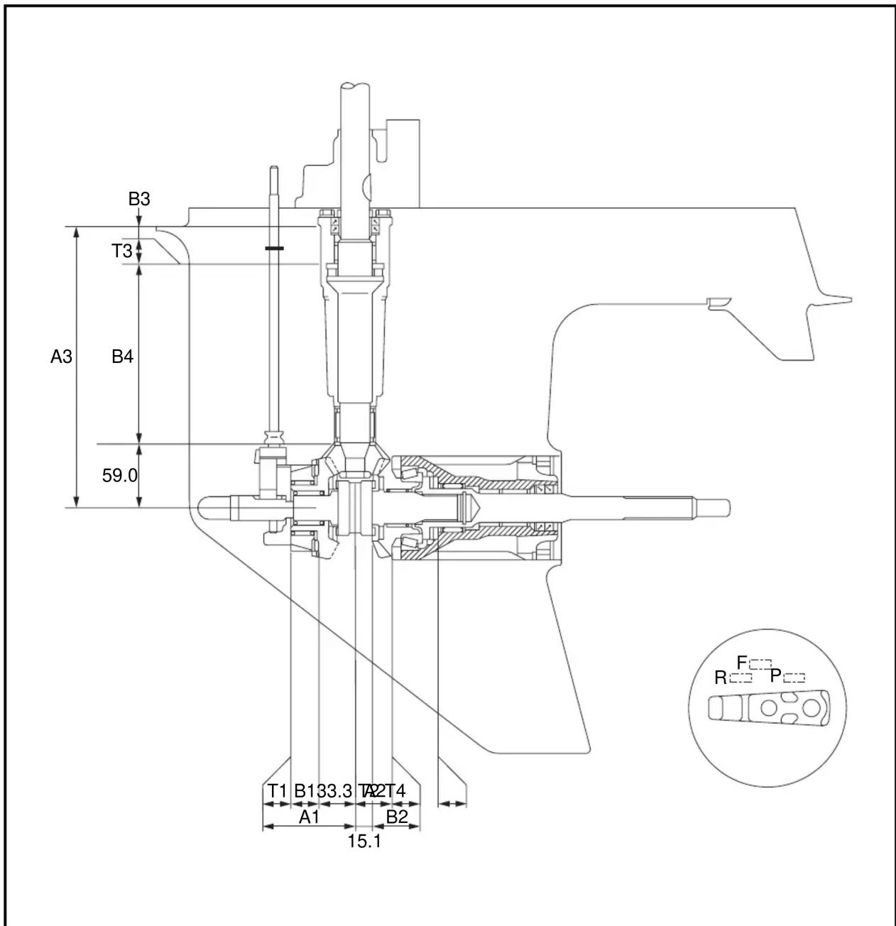
SELECTION DES CALES (MODELES A CONTRA-ROTATION) (POUR LES E.-U. ET LE CANADA)
N.B.:
NOTE: Find the shim thickness (T3) by selecting shims until the specified measurement (M) is obtained with the special tool.
1. Measure:
- Specified measurement (M) Out of specified value (M0) → Adjust.

Specified value (M0) = 1.00 + P/100 mm
Measuring steps
(1) Calculate the specified value (M0).
NOTE:
"P" is the deviation of the lower case dimension from standard. It is stamped on the trim tab mounting surface of the lower case in 0.01-mm units. If the "P" mark is missing or unreadable, assume a "P" value of "0", and check the backlash when the unit is assembled.
Example:
If "P" is "+5", then
M0 = 1.00 + (+5)/100 mm
$$ = 1. 0 0 + 0. 0 5 \mathrm{mm} $$
$$ = 1. 0 5 \mathrm{mm} $$
If "P" is "-3", then
M0 = 1.00 + (-3)/100 mm
$$ = 1. 0 0 - 0. 0 3 \mathrm{mm} $$
$$ = 0. 9 7 \mathrm{mm} $$
SELECTION DES CALES DE PIGNON
N.B.:
(2) Install the pinion height gauge, drive shaft, thrust bearing ①, and shim(s) ②.
| Pinion height gauge YB-34432-6, -11 |
NOTE: ____
If the original shim(s) is unavailable, start with a 0.50-mm shim.
(3) Install the pinion and pinion nut.
| Pinion nut 93 Nm (9.3 m • kgf, 67 ft • lb) |
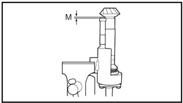
(4) Measure the specified measurement (M).
NOTE:
- Measure the clearance between the pinion height gauge and the lower surface of the pinion as shown.
- Perform the same measurement at three points on the pinion.
• Find the average of the measurements (M).
2. Adjust:
- Shim thickness (T3)
Remove or add shim(s).
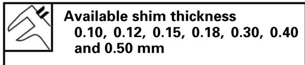
NOTE: ____
(M0) - (M) should be as close to "0" as possible.

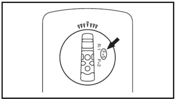
SELECTING THE REVERSE GEAR SHIMS
NOTE:
Find the shim thickness (T1) by selecting shims until the specified value (M0) is obtained with the special tool.
1. Measure:
- Specified measurement (M)
Out of specified value (M0) → Adjust.

Specified value (M0) = 25.30 + F/100 mm
Measuring steps
(1) Calculate the specified value (M0).
NOTE:
“F” is the deviation of the lower case dimension from standard. It is stamped on the trim tab mounting surface of the lower case in 0.01-mm units. If the “F” mark is missing or unreadable, assume an “F” value of “0”, and check the backlash when the unit is assembled.
Example:
If "F" is "+5", then
M0 = 25.30 + (+5)/100 mm
$$ = 2 5. 3 0 + 0. 0 5 \mathrm{mm} $$
$$ = 2 5. 3 5 \mathrm{mm} $$
If "F" is "-3", then
M0 = 25.30 + (-3)/100 mm
$$ = 2 5. 3 0 - 0. 0 3 \mathrm{mm} $$
$$ = 2 5. 2 7 \mathrm{mm} $$
SELECTION DES CALES DE REGLAGE DU PIGNON DE MARCHE ARRIERE
N.B.:
M0 = 25,30 + (+5)/100 mm
= 25,30 + 0,05 mm
= 25,35 mm
(2) Install the roller bearing ①, thrust bearing ②, and shim(s) ③.
NOTE:
If the original shim(s) is unavailable, start with a 0.50-mm shim.
(3) Measure the specified measurement (M).
2. Adjust:
- Shim thickness (T1) Remove or add shim(s).

Available shim thickness 0.10, 0.12, 0.15, 0.18, 0.30, 0.40 and 0.50 mm
NOTE: ____
(M0) - (M) should be as close to "0" as possible.
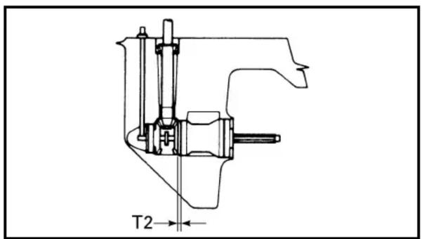

SELECTING THE FORWARD GEAR SHIMS
NOTE: ____
Find the shim thickness (T2) by selecting shims until the specified value (M0) is obtained with the special tool.
1. Measure:
- Specified measurement (M) Out of specified value (M0) → Adjust.

Specified value (M0) = 1.10 - R/100 mm
“R” is the deviation of the lower case dimension from standard. It is stamped on the trim tab mounting surface of the lower case in 0.01-mm units. If the “R” mark is missing or unreadable, assume an “R” value of “0”, and check the backlash when the unit is assembled.
Example:
If "R" is "+5", then
M0 = 1.10 - (+5)/100 mm
$$ = 1. 1 0 - 0. 0 5 \mathrm{mm} $$
$$ = 1. 0 5 \mathrm{mm} $$
If "R" is "-3", then
M0 = 1.10 - (-3)/100 mm
$$ = 1. 1 0 + 0. 0 3 \mathrm{mm} $$
$$ = 1. 1 3 \mathrm{mm} $$
(2) Install the shimming gauge, bearing, thrust washer, forward gear, and shim(s).
| Shimming gauge YB-34468-2 |
NOTE: \_\_\_\_
- If the original shim(s) is unavailable, start with a 0.50-mm shim.
- Turn the forward gear assembly a few times until the gear and bearing are horizontal.
(3) Measure the specified measurement (M).
LOWR

Etapes de la mesure
- Shim thickness (T2) Remove or add shim(s).

Available shim thickness 0.10, 0.12, 0.15, 0.18, 0.30, 0.40 and 0.50 mm
NOTE:
(M0) - (M) should be as close to "0" as possible.
SELECTING THE PROPELLER SHAFT SHIMS
NOTE:
Find the shim thickness (T4) by selecting shims until the specified measurement is obtained with the special tool.
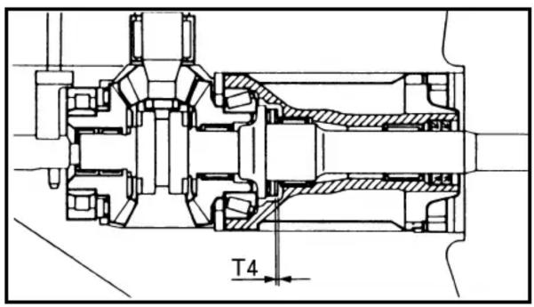

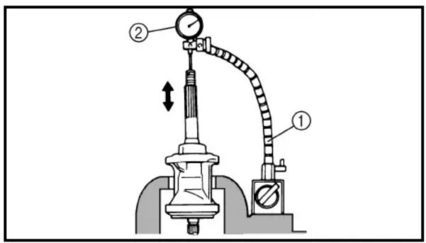
1. Install:
- Shim(s) ①
- Thrust bearing ②
- Propeller shaft ③
- Tapered roller bearing ④
2. Measure:
- Propeller shaft free play Out of specification → Adjust.

Propeller shaft free play 0.30 ± 0.05 mm

Magnetic base....① YU-34481 / 90890-06705 Dial gauge set....② YU-03097 / 90890-01252
3. Adjust:
- Propeller shaft free play Remove or add shim(s).

Available shim thickness 0.10, 0.12, 0.15, 0.18, 0.30, 0.40 and 0.50 mm
2. Régler:
SHIMMING (COUNTER ROTATION MODELS) (FOR WORLDWIDE)
NOTE:
- There is no need to select shims when reassembling with the original case and inner parts.
- Shim calculations are required when reassembling with the original inner parts and a new case (the difference between the original inner parts and the new case).
• Measurements and adjustments are required when replacing the inner part(s).

SELECTION DES CALES (MODELES A CONTRA- ROTATION) (POUR LE RESTE DU MONDE)
N.B.:
Select the shim thickness (T3) by using the specified measurement(s) and the calculation formula.
Select:
- Shim thickness (T3)
Selecting steps
(1) Measure (M3).
| Digital caliper 90890-06704 |
NOTE: ____
Install the bearing housing ①, thrust bearing ②, and washer ③.
(2) Install the pinion and pinion nut.
| Pinion nut 93 Nm (9.3 m • kgf, 67 ft • lb) |
(3) Install the pinion height gauge.
| Pinion height gauge 90890-06702 |
NOTE: ____
After the wing nuts contact the fixing plate, tighten them another 1/4 of a turn.
(4) Measure (M4).
| Digital caliper 90890-06704 |
NOTE: ____
- Measure the clearance between the pinion height gauge and the pinion, as shown.
- Perform the same measurement at three points on the pinion.
- Find the average of the measurements (M4).
SELECTION DES CALES DE PIGNON
N.B.:
Pinion shim thickness (T3) = 62.5 + P/100 - M3 - M4
NOTE:
"P" is the deviation of the lower case dimension from standard. It is stamped on the trim tab mounting surface of the lower case in 0.01-mm units. If the "P" mark is missing or unreadable, assume a "P" value of "0", and check the backlash when the unit is assembled.
Example:
If M3 is “46.85 mm”, M4 is “15.12 mm” and P is “-5”, then
T3 = 62.5 + (-5)/100 - 46.85 - 15.12 mm
= 62.5 - 0.05 - 46.85 - 15.12 mm
= 0.48 mm
(6) Select the pinion shim(s) (T3).
| Calculated numeral at 1/100th place | Rounded numeral | |
| More than or less | ||
| 0.00 0.02 | 0.00 | |
| 0.02 0.05 | 0.02 | |
| 0.05 0.08 | 0.05 | |
| 0.08 0.10 | 0.08 | |
| Available shim thickness0.10, 0.12, 0.15, 0.18, 0.30, 0.40 and 0.50 mm | |

SELECTING THE REVERSE GEAR SHIMS
NOTE:
Select the shim thickness (T1) by using the specified measurement(s) and the calculation formula.
Select:
- Shim thickness (T1)
Selecting steps
(1) Measure (M1).

Digital caliper 90890-06704
NOTE:
- Measure the combined thickness of the roller bearing ① and thrust bearing ②.
- Turn the roller bearing outer race two or three times so the rollers seat. Then, measure the height of the bearing, as shown.
- Perform the same measurement at three points on the roller bearing outer race.
- Find the average of the measurements (M1).
(2) Calculate the reverse gear shim thickness (T1).

Reverse gear shim thickness (T1) (T1) = 25.3 + F/100 - M1
NOTE:
“F” is the deviation of the lower case dimension from standard. It is stamped on the trim tab mounting surface of the lower case in 0.01-mm units. If the “F” mark is missing or unreadable, assume an “F” value of “0”, and check the backlash when the unit is assembled.
SELECTION DES CALES DE REGLAGE DU PIGNON DE MARCHE ARRIERE
N.B.:
If M1 is "24.80 mm" and F is "+5", then
T1 = 25.3 + (+5)/100 - 24.80 mm
= 25.3 + 0.05 - 24.80 mm
= 0.55 mm
(3) Select the reverse gear shim(s).
| Calculated numeral at 1/100th place | Rounded numeral | |
| More than or less | ||
| 0.00 0.02 | 0.00 | |
| 0.02 0.05 | 0.02 | |
| 0.05 0.08 | 0.05 | |
| 0.08 0.10 | 0.08 | |
| Available shim thickness0.10, 0.12, 0.15, 0.18, 0.30, 0.40 and 0.50 mm | |
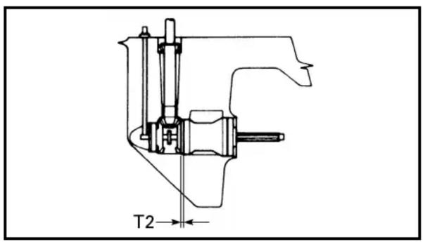

SELECTING THE FORWARD GEAR SHIMS
NOTE:
Select the shim thickness (T2) by using the specified measurement(s) and the calculation formula.
Select:
- Shim thickness (T2)
Selecting steps
(1) Measure (M2).

NOTE:
- Measure the height of the gear as shown.
- Perform the same measurement at three points on the gear.
- Find the average of the measurements (M2).
Exemple:
(2) Calculate the forward gear shim thickness (T2).

Forward gear shim thickness (T2) = M2 - 28.1 - R/100
NOTE:
“R” is the deviation of the lower case dimension from standard. It is stamped on the trim tab mounting surface of the lower case in 0.01-mm units. If the “R” mark is missing or unreadable, assume a “R” value of “0”, and check the backlash when the unit is assembled.
Example:
If M2 is "29.10 mm", R is "+2", then
T2 = 29.10 - 28.1 - (+2)/100 mm
= 29.10 - 28.1 - 0.02 mm
= 0.98 mm
(3) Select the forward gear shim(s) (T2).
| Calculated numeral at 1/100th place | Rounded numeral | |
| More than or less | ||
| 0.00 0.02 | 0.02 | |
| 0.02 0.05 | 0.05 | |
| 0.05 0.08 | 0.08 | |
| 0.08 0.10 | 0.10 | |
 | Available shim thickness0.10, 0.12, 0.15, 0.18, 0.30, 0.40 and 0.50 mm | |
LOWR


SELECTING THE PROPELLER SHAFT SHIMS
NOTE:
Find the shim thickness (T4) by selecting shims until the specified measurement is obtained with the special tool.
1. Install:
- Shim(s) ①
- Thrust bearing ②
- Propeller shaft ③
- Tapered roller bearing ④
2. Measure:
- Propeller shaft free play Out of specification → Adjust.

Propeller shaft free play 0.30 ± 0.05 mm

Magnetic base....① YU-34481 / 90890-06705 Dial gauge set....② YU-03097 / 90890-01252
3. Adjust:
- Propeller shaft free play Remove or add shim(s).

Available shim thickness 0.10, 0.12, 0.15, 0.18, 0.30, 0.40 and 0.50 mm
SELECTION DES CALES D'ARBRE PORTE-HELICE
N.B.:
- Do not install the water pump components when measuring the backlash.
- Measure both the forward and reverse gear backlashes.
- If both the forward and reverse gear back-lashes are larger than specification, the pinion may be too high.
- If both the forward and reverse gear back-lashes are smaller than specification, the pinion may be too low.
MEASURING THE FORWARD GEAR BACKLASH
1. Measure:
- Forward gear backlash Out of specification → Adjust.

Forward gear backlash 0.15 - 0.30 mm (0.006 - 0.012 in)


Measuring steps
(1) Set the shift rod into the neutral position.

Shift rod wrench YB-06052 / 90890-06052
(2) Install the propeller shaft housing puller so it pushes against the propeller shaft.

Propeller shaft housing puller. ① YB-06207 / 90890-06502
Universal puller.... ② YB-06117 / 90890-06521
Guide plate.... ③ 90890-06501
Center bolt ④ 90890-06504

Center bolt 10 Nm (1.0 m · kgf, 7.2 ft · lb)
JEU DE RETOUR (MODELES A CONTRA- ROTATION)
N.B.:
(3) Install the backlash indicator onto the drive shaft (on the 22.4 mm (0.88 in) diameter portion of the drive shaft).
| Backlash indicator ........ ⑤ YB-06265 / 90890-06706 |
(4) Install the dial gauge onto the lower unit and have the dial gauge plunger contact the mark on the backlash indicator.

(5) Set the lower unit upside down.
(6) Slowly turn the drive shaft clockwise and counterclockwise. When the drive shaft stops in each direction, measure the backlash.
2. Adjust:
- Forward gear shim Remove or add shim(s).
| Forward gear backlash | Shim thickness | |
| Less than 0.15 mm (0.006 in) | To be increased by (0.23 – M) · 0.58 | |
| More than 0.30 mm (0.012 in) | To be decreased by (M – 0.23) · 0.58 | |
M: Measurement
MEASURING THE REVERSE GEAR BACKLASH
1. Measure:
- Reverse gear backlash Out of specification → Adjust.
| Reverse gear backlash 0.5 - 0.7 mm (0.020 - 0.028 in) |


Measuring steps
(1) Set the shift rod into the neutral position.

Shift rod wrench YB-06052 / 90890-06052
(2) Load the reverse gear by installing the propeller without the spacer and then tighten the propeller nut.

Propeller nut 5 Nm (0.5 m · kgf, 3.6 ft · lb)
(3) Install the backlash indicator onto the drive shaft (on the 22.4 mm (0.88 in) diameter portion of the drive shaft).

Backlash indicator .... ① YB-06265 / 90890-06706
(4) Install the dial gauge onto the lower unit and have the dial gauge plunger contact the mark on the backlash indicator.

Magnetic base attaching plate....② YB-07003 / 90890-07003 Dial gauge set....③ YU-03097 / 90890-01252 Magnetic base....④ YU-34481 / 90890-06705
(5) Set the lower unit upside down.
(6) Turn the shift rod into the reverse position with the shift rod wrench.
(7) Turn the drive shaft clockwise until the clutch dog is fully engaged.
(8) Turn the shift rod into the neutral position with the shift rod wrench.
(9) Turn the drive shaft counterclockwise approximately 30^ more.
LOWR

Etapes de la mesure
(10) Turn the shift rod into the reverse position with the shift rod wrench.
(11) Slowly turn the drive shaft clockwise and counterclockwise. When the drive shaft stops in each direction, measure the backlash.
NOTE:
When measuring the reverse gear backlash, turn the shift rod wrench towards the reverse position with force.
2. Adjust:
- Reverse gear shim
Remove or add shim(s).
| Reverse gear backlash | Shim thickness | |
| Less than 0.5 mm (0.020 in) | To be decreased by (0.6 – M) · 0.58 | |
| More than 0.7 mm (0.028 in) | To be increased by (M – 0.6) · 0.58 | |
M: Measurement
STEERING HANDLE (OPTION) 7-1
REMOVING/INSTALLING THE STEERING FRICTION.... 7-1
REMOVING/INSTALLING THE STEERING HANDLE 7-2
DISASSEMBLING/ASSEMBLING THE STEERING HANDLE.... 7-4
DISASSEMBLING/ASSEMBLING THE STEERING HANDLE
SUB ASSEMBLY 7-7
SHIFT ROD ASSEMBLY 7-10
REMOVING/INSTALLING THE SHIFT ROD ASSEMBLY 7-10
BOTTOM COWLING 7-13
REMOVING/INSTALLING THE BOTTOM COWLING 7-13
UPPER CASE ASSEMBLY 7-16
REMOVING/INSTALLING THE UPPER CASE ASSEMBLY 7-16
DISASSEMBLING/ASSEMBLING THE UPPER CASE ASSEMBLY ..... 7-18
OIL PAN....7-21
DISASSEMBLING/ASSEMBLING THE OIL PAN 7-21
CLAMP BRACKETS 7-24
REMOVING/INSTALLING THE CLAMP BRACKETS.... 7-24
STEERING ARM....7-26
REMOVING/INSTALLING THE STEERING ARM.... 7-26
SWIVEL BRACKET ASSEMBLY 7-27
DISASSEMBLING/ASSEMBLING THE SWIVEL BRACKET
ASSEMBLY....7-27
POWER TRIM AND TILT UNIT 7-29
REMOVING/INSTALLING THE POWER TRIM AND TILT UNIT...... 7-29
REMOVING THE POWER TRIM AND TILT UNIT 7-31
BLEEDING THE POWER TRIM AND TILT UNIT 7-31
CHAPITRE 7 UNITE DE SUPPORT
POIGNEE DE DIRECTION
(OPTION)....7-1
DEPOSE/INSTALLATION DE LA FRICTION DE DIRECTION .....7-1
DEPOSE/INSTALLATION DE LA POIGNEE DE DIRECTION....7-2
DEMONTAGE/MONTAGE DE LA POIGNEE DE DIRECTION....7-4
DEMONTAGE/MONTAGE DU SOUS-ENSEMBLE DE LA POIGNEE DE DIRECTION......7-7
ENSEMBLE DE LA TIGE DE
SELECTION 7-10
DEPOSE/INSTALLATION DE L'ENSEMBLE DE TIGE DE SELECTION....7-10
CARENAGE INFERIEUR....7-13
DEPOSE/INSTALLATION DU CARENAGE INFERIEUR......7-13
ENSEMBLE DU CARTER
SUPERIEUR 7-16
DEPOSE/INSTALLATION DE L'ENSEMBLE DU CARTER SUPERIEUR....7-16
DEMONTAGE/MONTAGE DE L'ENSEMBLE DU CARTER SUPERIEUR....7-18
CARTER D'HUILE....7-21
DEMONTAGE/MONTAGE DU CARTER D'HUILE....7-21
SUPPORTS DE SERRAGE .....7-24
DEPOSE/INSTALLATION DES SUPPORTS DE SERRAGE .....7-24
BRAS DE DIRECTION......7-26
DEPOSE/INSTALLATION DU BRAS DE DIRECTION .....7-26
ENSEMBLE DU SUPPORT
PIVOTANT 7-27
DEMONTAGE/MONTAGE DE L'ENSEMBLE DU SUPPORT PIVOTANT.... 7-27
UNITE DU SYSTEME D'ASSIETTE
ET D'INCLINAISON ASSISTEES ..7-29
DEPOSE/INSTALLATION DE L'UNITE DU SYSTEME D'ASSIETTE ET D'INCLINAISON
ASSISTEES....7-29
DEPOSE DE L'UNITE DU SYSTEME D'ASSIETTE ET D'INCLINAISON ASSISTEES ....7-31
PURGE DE L'UNITE DU SYSTEME D'ASSIETTE ET D'INCLINAISON ASSISTEES ....7-31
ESTIBADO MOTORIZADO Y
CHECKING THE RESERVOIR.... 7-34
CHECKING THE GEAR PUMP HOUSING FILTER 7-34
INSTALLING THE POWER TRIM AND TILT MOTOR.... 7-35
FILLING THE RESERVOIR.... 7-36
BLEEDING THE POWER TRIM AND TILT UNIT 7-36
MEASURING THE HYDRAULIC PRESSURE 7-38
TILT RAM ASSEMBLY AND GEAR PUMP UNIT 7-41
REMOVING/INSTALLING THE TILT RAM ASSEMBLY AND GEAR PUMP UNIT 7-41
REMOVING THE TILT RAM END SCREW 7-43
REMOVING THE GEAR PUMP UNIT 7-43
DISASSEMBLING THE GEAR PUMP UNIT 7-43
CHECKING THE TILT RAM 7-44
CHECKING THE GEAR PUMP UNIT.... 7-44
ASSEMBLING THE GEAR PUMP UNIT 7-45
INSTALLING THE GEAR PUMP UNIT.... 7-46
INSTALLING THE TILT RAM ASSEMBLY 7-46
TRIM RAM ASSEMBLIES AND FREE PISTON 7-48
REMOVING/INSTALLING THE TRIM RAM ASSEMBLIES AND FREE PISTON 7-48
REMOVING THE TRIM RAM END SCREWS 7-49
REMOVING THE FREE PISTON.... 7-49
CHECKING THE TRIM RAMS 7-50
CHECKING THE FREE PISTON.... 7-50
CHECKING THE TRIM RAM CYLINDERS 7-50
INSTALLING THE FREE PISTON.... 7-50
INSTALLING THE TRIM RAMS 7-51
RESERVOIR ET MOTEUR DU SYSTÈME D'ASSIETTE ET
D'INCLINAISON ASSISTEES .....7-33
DEPOSE/INSTALLATION DU RESERVOIR ET DU MOTEUR DU SYSTÈME D'ASSIETTE ET D'INCLINAISON ASSISTEES ....7-33
VERIFICATION DU RESERVOIR ....7-34
VERIFICATION DU FILTRE DU LOGEMENT DE LA POMPE A ENGRENAGES....7-34
INSTALLATION DU MOTEUR DU SYSTEME D'ASSIETTE ET D'INCLINAISON ASSISTEES ....7-35
REMLISSAGE DU RESERVOIR .7-36 PURGE DE L'UNITE DU
SYSTEME D'ASSIETTE ET D'INCLINAISON ASSISTEES ....7-36
MESURE DE LA PRESSION HYDRAULIQUE ....7-38
ENSEMBLE DE VERIN
D'INCLINAISON ET UNITE DE
POMPE A ENGRENAGES ......7-41
DEPOSE/INSTALLATION DE L'ENSEMBLE DU VERIN D'INCLINAISON ET DE L'UNITE DE POMPE A ENGRENAGES ....7-41
DEPOSE DE LA VIS CAPUCHON DU VERIN D'INCLINAISON.....7-43
DEPOSE DE L'UNITE DE POMPE A ENGRENAGES......7-43
DEMONTAGE DE L'UNITE DE LA POMPE A ENGRENAGES ....7-43 VERIFICATION DU VERIN D'INCLINAISON....7-44
VERIFICATION DE L'UNITE DE LA POMPE A ENGRENAGES ....7-44
MONTAGE DE L'UNITE DE LA POMPE A ENGRENAGES....7-45
INSTALLATION DE L'UNITE DE LA POMPE A ENGRENAGES ....7-46
INSTALLATION DE L'ENSEMBLE DU VERIN D'INCLINAISON.....7-46
ENSEMBLES DU VERIN D'ASSIETTE ET PISTON LIBRE....7-48
DEPOSE/INSTALLATION DES ENSEMBLES DU VERIN D'ASSIETTE ET DU PISTON LIBRE....7-48
DEPOSE DES VIS CAPUCHON DU VERIN D'ASSIETTE......7-49
DEPOSE DU PISTON LIBRE .....7-49 VERIFICATION DES VERINS D'ASSIETTE.....7-50
VERIFICATION DU PISTON LIBRE.... 7-50
VERIFICATION DES CYLINDRES DU VERIN D'ASSIETTE......7-50 INSTALLATION DU PISTON
LIBRE.... 7-50 INSTALLATION DES VERINS
D'ASSIETTE....7-51
BEHÄLTER UND SERVO-TRIMM
UND KIPPMOTOR 7-33
AUSBAU/EINBAU DES BEHÄLTERS UND SERVO- TRIMM UND KIPPMOTOR .....7-33
ÜBERPRÜFUNG DES BEHÄLTERS 7-34
STEERING HANDLE (OPTION)
REMOVING/INSTALLING THE STEERING FRICTION

| Order | Job/Part Q'ty Remarks | ||
| 1 Nut 12 Washer 13 Bolt 14 Nut 15 Link rod 16 Washer 27 Wing nut 18 Bolt 19 Friction rod 110 Friction piece 1 | |||
| For installation, reverse the removal procedure. | |||
POIGNEE DE DIRECTION (OPTION)
DEPOSE/INSTALLATION DE LA FRICTION DE DIRECTION
REMOVING/INSTALLING THE STEERING HANDLE

| Order | Job/Part Q'ty Remarks | ||
| 1 | Bolt 2 | ||
| 2 | Fitting plate 1 | ||
| 3 | Clip 2 | ||
| 4 | Throttle cable 1 | ||
| 5 | Bolt 1 | ||
| 6 | Cable clamp 1 | ||
| 7 | Shift cable 1 | ||
| 8 | Bolt 1 | ||
| 9 | Plate 1 | ||
| 10 | Bolt 1 | ||
| Continued on next page. |
DEPOSE/INSTALLATION DE LA POIGNEE DE DIRECTION
Order Job/Part Q'ty Remarks
1 Engine stop switch leads 2
2 Bolt 1
3 Bolt 1
4 Nut 1
5 Screw 1
6 Cover 1
7 Main switch assembly 1
8 Holder 1
Continued on next page.
DEMONTAGE/MONTAGE DE LA POIGNEE DE DIRECTION
| Order | Job/Part Q'ty Remarks | ||
| 9 Screw 1 | |||
| 10 Throttle grip 1 | |||
| 11 Washer 1 | |||
| 12 Spring 1 | |||
| 13 Bushing 1 | |||
| 14 Screw 5 | |||
| 15 Screw 2 | |||
| 16 Cover 1 | |||
| 17 Screw 2 | |||
| Continued on next page. | |||
| Order | Job/Part Q'ty Remarks | ||
| 18 | Power trim and tilt switch 1 | ||
| 19 | Nut 1 | ||
| 20 | Engine stop lanyard switch 1 | ||
| 21 | Screw 2 | ||
| 22 | Shift lever cover 1 | ||
| 23 | Bolt 1 | ||
| 24 | Shift lever 1 | ||
| 25 | Bushing 1 | ||
| 26 | Steering handle sub assembly 1 | ||
| For assembly, reverse the disassembly procedure. |
| Order | Job/Part Q'ty Remarks | ||
| 1 | Clip 1 | ||
| 2 | Cable clamp 1 | ||
| 3 | Throttle cable (short) 1 | ||
| 4 | Bolt 1 | ||
| 5 | Shift cable bracket 1 | ||
| 6 | Cotter pin 1 | ||
| 7 | Friction adjusting knob 1 | ||
| 8 | Bolt 1 | ||
| 9 | Bolt 2 | ||
| 10 | Throttle shaft 1 | ||
| 11 | Friction piece 1 | ||
| Continued on next page. |
DEMONTAGE/MONTAGE DU SOUS-ENSEMBLE DE LA POIGNEE DE DIRECTION
| Order | Job/Part Q'ty Remarks | ||
| 12 | Frame 1 | ||
| 13 | Clip 1 | ||
| 14 | Shift cable (long) 1 | ||
| 15 | Throttle arm shaft 1 | ||
| 16 | Throttle arm 1 | ||
| 17 | Screw 2 | ||
| 18 | Spring housing 1 | ||
| 19 | Roller 1 | ||
| 20 | Actuator 1 | ||
| 21 | Spring 1 | ||
| 22 | Shift arm 1 | ||
| Continued on next page. |
| Order | Job/Part Q'ty Remarks | ||
| 23 | Bushing 1 | ||
| 24 | Nut 1 | ||
| 25 | Washer 1 | ||
| 26 | Bolt 1 | ||
| 27 | Washer 1 | ||
| 28 | Wave washer 1 | ||
| 29 | Collar 1 | ||
| 30 | Bracket 1 | ||
| 31 | Washer 1 | ||
| 32 | Bushing 2 | ||
| 33 | Steering handle 1 | ||
| For assembly, reverse the disassembly procedure. |
REMOVING/INSTALLING THE SHIFT ROD ASSEMBLY

| Order | Job/Part Q'ty Remarks | ||
| Power unit assembly Refer to “POWER UNIT” on page 5-4. | |||
| 1 Screw 2 | |||
| 2 Plate 1 | |||
| 3 Shift position switch 1 | |||
| 4 Clip 1 | |||
| 5 Bushing 1 | |||
| 6 Bolt 2 | |||
| 7 Shift bracket 1 | |||
| Continued on next page. | |||
ENSEMBLE DE LA TIGE DE SELECTION
DEPOSE/INSTALLATION DE L'ENSEMBLE DE TIGE DE SELECTION
| Order | Job/Part Q'ty Remarks | ||
| 17 | Bolt 2 | ||
| 18 | Bracket 1 | ||
| 19 | Bolt 2 | ||
| 20 | Shift rod bracket 1 | ||
| 21 | Bushing 2 | ||
| 22 | Shift rod 1 | ||
| 23 | Grommet 1 | ||
| 24 | O-ring 1 | ||
| For installation, reverse the removal procedure. |
| Order | Job/Part Q'ty Remarks | ||
| Power unit Refer to “POWER UNIT” on page 5-4. | |||
| 1 Bolt 4 | |||
| 2 Bolt 2 | |||
| 3 Spring hook 2 | |||
| 4 Spring 2 | |||
| 5 Bolt 2 | |||
| 6 Washer 2 | |||
| 7 Clamp lever 2 | |||
| 8 Wave washer 2 | |||
| 9 Bushing 4 | |||
| 10 Clamp lever 2 | |||
| Continued on next page. | |||
CARENAGE INFERIEUR
DEPOSE/INSTALLATION DU CARENAGE INFERIEUR
| Order | Job/Part Q'ty Remarks | ||
| Lower unit Refer to “LOWER UNIT | (REGULAR ROTATION MODELS)” on page 6-1 and “LOWER UNIT (COUNTER ROTATION MODELS)” on page 6-26. | ||
| Bottom cowling Refer to “BOTTOM COWLING” on page 7-13. | |||
| 1 Bolt 6 | |||
| 2 Oil pump 1 | |||
| 3 Seal 1 | |||
| 4 Dowel pin 2 | |||
| 5 O-ring 2 | |||
| 6 Bolt 4 | |||
| Continued on next page. | |||
ENSEMBLE DU CARTER SUPERIEUR
DEPOSE/INSTALLATION DE L'ENSEMBLE DU CARTER SUPERIEUR
| Order | Job/Part Q'ty Remarks | ||
| 7 | Lower mount cover 2 | ||
| 8 | Grease nipple 1 | ||
| 9 | Bolt 1 | ||
| 10 | Damper 2 | ||
| 11 | Nut 2 | ||
| 12 | Nut 2 | ||
| 13 | Washer 2 | ||
| 14 | Ground lead 1 | ||
| 15 | Washer 2 | ||
| 16 | Upper case assembly 1 | ||
| For installation, reverse the removal procedure. |
| Order | Job/Part Q'ty Remarks | ||
| 1 | Bolt 4 | ||
| 2 | Upper mount rubber 1 | ||
| 3 | Bolt 2 | ||
| 4 | Plate 1 | ||
| 5 | Bolt 2 | ||
| 6 | Washer 2 | ||
| 7 | Rubber 2 | ||
| 8 | Lower mount rubber 2 | ||
| 9 | Washer 2 | ||
| Continued on next page. |
DEMONTAGE/MONTAGE DE L'ENSEMBLE DU CARTER SUPERIEUR
| Order | Job/Part Q'ty Remarks | ||
| 10 | Bolt 4 | ||
| 11 | Muffler assembly 1 | ||
| 12 | Gasket 1 | Not reusable | |
| 13 | Rubber gasket 1 | ||
| 14 | Rubber seal 1 | ||
| 15 | Grommet 1 | ||
| 16 | Screw 2 | ||
| 17 | Baffle plate 1 | ||
| 18 | Damper 1 | ||
| Continued on next page. |
| Order | Job/Part Q'ty Remarks | ||
| 19 Grommet 120 Circlip 121 Drive shaft bushing 122 Upper case 1 | For assembly, reverse the disassembly procedure. |
| Order | Job/Part Q'ty Remarks | ||
| 1 | Bolt 6 | ||
| 2 | Bolt 1 | ||
| 3 | Muffler 1 | ||
| 4 | Dowel pin 2 | ||
| 5 | Spacer 1 | ||
| 6 | Grommet 1 | ||
| 7 | Water pipe 1 | ||
| 8 | Rubber seal 1 | ||
| Continued on next page. |
CARTER D'HUILE
DEMONTAGE/MONTAGE DU CARTER D'HUILE
| Order | Job/Part Q'ty Remarks | ||
| 17 | Bolt 3 | ||
| 18 | Collar 3 | ||
| 19 | Oil strainer 1 | ||
| 20 | Rubber gasket 1 | Not reusable | |
| 21 | Gasket 1 | Not reusable | |
| 22 | Exhaust guide 1 | ||
| For assembly, reverse the disassembly procedure. |
REMOVING/INSTALLING THE CLAMP BRACKETS

| Order | Job/Part Q'ty Remarks | ||
| Upper case assembly Refer to “UPPER CASE ASSEMBLY” on 1 Grease nipple 42 Ground lead 13 Bolt 44 Ground lead 15 Anode bracket 26 Anode 17 Trim sensor 18 Self-locking nut 1 | page 7-16. | ||
| Continued on next page. | |||
SUPPORTS DE SERRAGE
DEPOSE/INSTALLATION DES SUPPORTS DE SERRAGE
REMOVING/INSTALLING THE STEERING ARM


| Order | Job/Part Q'ty Remarks | ||
| Upper case assembly Refer to “UPPER CASE ASSEMBLY” on 1 Circlip 12 Steering arm yoke 13 Washer 14 Washer 15 O-ring 16 Steering arm 17 Washer 18 Bushing 29 Swivel bracket assembly 1 | For installation, reverse the removal procedure. |
BRAS DE DIRECTION
DEPOSE/INSTALLATION DU BRAS DE DIRECTION
| Order | Job/Part Q'ty Remarks | ||
| Steering arm Refer to “STEERING 1 Nut 22 Trim stopper 23 Bolt 14 Spring holder 15 Spring 16 Pin 2 | ARM” | on page 7-26.Continued on next page. |
ENSEMBLE DU SUPPORT PIVOTANT
DEMONTAGE/MONTAGE DE L'ENSEMBLE DU SUPPORT PIVOTANT
REMOVING/INSTALLING THE POWER TRIM AND TILT UNIT

| Order | Job/Part Q'ty Remarks | ||
| Tilt up the outboard1 Power trim and tilt lead 22 Plastic locking tie 33 Bolt 14 Ground lead 15 Circlip 16 Upper mounting pin 1 | Not reusableContinued on next page. |
BRKT

UNITE DU SYSTEME D'ASSIETTE ET D'INCLINAISON ASSISTEES
REMOVING THE POWER TRIM AND TILT UNIT
WARNING
After tilting up the outboard, be sure to support it with the tilt stop levers.
Otherwise, the outboard could suddenly lower if the power trim and tilt unit should lose fluid pressure.
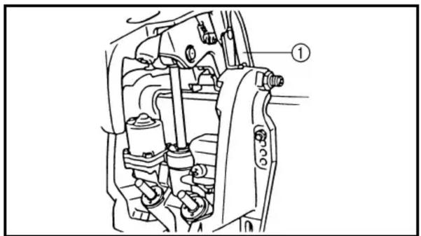
NOTE: ____
Tilt up the outboard and then turn the tilt stop levers ① to support it.
Remove:
- Power trim and tilt unit
NOTE: ____
Slightly lower the tilt ram assembly and then remove the power trim and tilt unit.

BLEEDING THE POWER TRIM AND TILT UNIT
NOTE: ____
Install the power trim and tilt unit onto the outboard before bleeding.
Bleed:
- Air bubbles
(from the power trim and tilt unit)
Bleeding steps
(1) Connect the battery leads to the battery.
(2) Loosen the manual valve ① by turning it counterclockwise until it stops.
BRKT

DEPOSE DE L'UNITE DU SYSTEME D'ASSIETTE ET D'INCLINAISON ASSISTEES
AVERTISSEMENT
natural_image
Technical line drawing of a mechanical assembly with no visible text or symbols
(3) Tilt up the outboard fully, then release it, and let it lower by its own weight.
(4) Tighten the manual valve by turning it clockwise.
(5) Let the power trim and tilt fluid settle for about 5 minutes.
(6) Push and hold the power trim and tilt switch in the up position until the outboard is fully tilted up.
(7) Turn the tilt stop levers to support the outboard. Then, let the power trim and tilt fluid settle for about 5 minutes.
(8) Remove the reservoir cap ② and check that fluid is up to the brim as shown. Add fluid if the level is below the brim.
(9) Install the power trim and tilt reservoir cap.
(10) Repeat the above steps two or three times until the power trim and tilt fluid is at the correct level.
BRKT

UNITE DU SYSTEME D'ASSIETTE ET D'INCLINAISON ASSISTEES
| Order | Job/Part Q'ty Remarks | ||
| Power trim and tilt unit Refer to “POWER | TRIM AND TILT UNIT”on page 7-29. | ||
| 1 Reservoir cap 1 | |||
| 2 Bolt 3 | |||
| 3 Reservoir 1 | |||
| 4 Bolt 4 | |||
| 5 Power trim and tilt motor 1 | |||
| 6 O-ring 1 | |||
| 7 Drive pin 1 | |||
| 8 Gear pump housing filter 1 | |||
| For installation, reverse the removal procedure. | |||
RESERVOIR ET MOTEUR DU SYSTEME D'ASSIETTE ET D'INCLINAISON
ASSISTEES
DEPOSE/INSTALLATION DU RESERVOIR ET DU MOTEUR DU SYSTEME D'ASSIETTE ET D'INCLINAISON ASSISTEES
- To prevent the hydraulic fluid from spurting out due to internal pressure, the outboard should be kept fully tilted up (the tilt rod at full length).
- After removing the power trim and tilt motor or reservoir, do not push the tilt ram down. This may cause hydraulic fluid to spurt out from the port.
CAUTION:
Do not wipe hydraulic system components with rags, paper, tissues, or the like, as fibers from such material will cause malfunctions if they enter the system.
CHECKING THE RESERVOIR
- Drain:
• Power trim and tilt fluid
- Check:
- Reservoir
Cracks/damage/leaks → Replace.
CHECKING THE GEAR PUMP HOUSING FILTER
Check:
- Gear pump housing filter Damage/tears → Replace. Foreign matter → Clean.
BRKT

AVERTISSEMENT
INSTALLING THE POWER TRIM AND TILT MOTOR
1. Install:
- Gear pump housing filter ①
- Drive pin ②
2. Fill:
- Gear pump housing

Recommended power trim and tilt fluid ATF Dexron II
NOTE:
Add power trim and tilt fluid until it reaches the top of the gear pump housing.
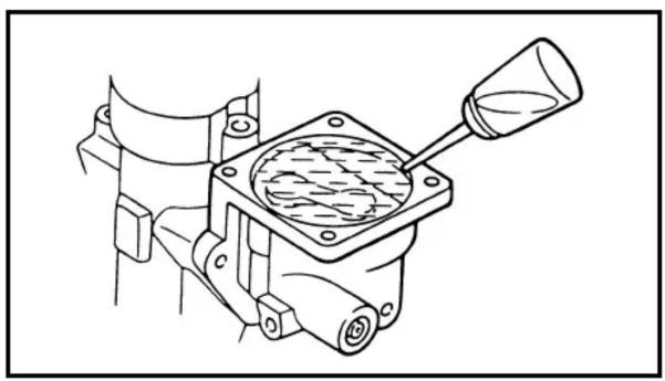
natural_image
Technical line drawing of a mechanical component with a lever and housing (no text or symbols)3. Bleed:
- Air bubbles
NOTE:
- Remove all of the air bubbles with a syringe or suitable tool as shown.
- Turn the gear pump gears with a screw-driver and then remove any air between the gear teeth.
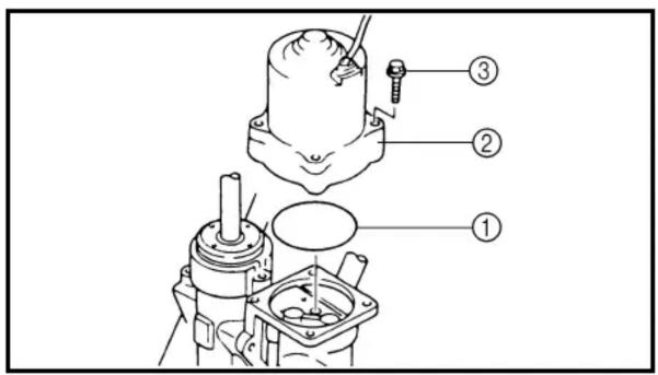
4. Install:
- O-ring ①
• Power trim and tilt motor ② - Bolt ③
NOTE:
Align the armature shaft with the recess in the drive pin.
BRKT

INSTALLATION DU MOTEUR DU SYSTEME D'ASSIETTE ET D'INCLINAISON ASSISTEES
To prevent the hydraulic fluid from spurting out due to internal pressure, the tilt ram should be kept at full length.
- Fill:
- Reservoir

natural_image
Line drawing of a mechanical component with a tool inserted, showing internal structure and mounting holes (no text or symbols)
Recommended power trim and tilt fluid ATF Dexron II
- Check:
- Power trim and tilt fluid level Level is low → Add power trim and tilt fluid to the proper level.
BLEEDING THE POWER TRIM AND TILT UNIT
NOTE: ____
This bleeding must be done before installing the power trim and tilt unit onto the outboard.
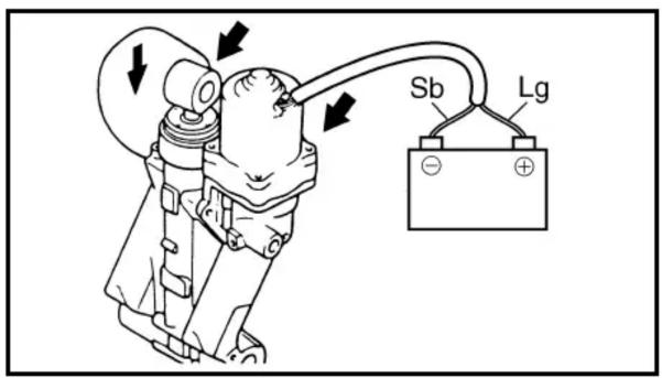
- Bleed:
• Air bubbles (from the power trim and tilt unit)
Bleeding steps
(1) Set the power trim and tilt unit upright.
(2) Connect the leads of the power trim and tilt on the battery terminals until the trim and tilt ram assemblies are fully compressed.
NOTE:
If the rams will not go down, refer to the following.
A. Connect the leads of the power trim and tilt on the battery terminals until the trim and tilt ram assemblies are fully extended. Then, reverse the leads on the battery terminals until the trim and tilt ram assemblies are fully compressed.

BRKT

REMLISSAGE DU RESERVOIR
AVERTISSEMENT
B. If step A was unsuccessful, connect the leads on the battery terminals and fully compress the tilt ram assembly by hand.
C. If step B was unsuccessful, loosen the manual valve, compress the trim and tilt ram assemblies fully by hand, and then tighten the manual valve. Then, compress and extend the trim and tilt ram assemblies by connecting the leads on the battery terminals in the up and down positions.
D. If step C was unsuccessful, disassemble, check, and correct any problems with the power trim and tilt unit.


natural_image
Line drawing of a mechanical component with a tool inserted, showing internal structure and mounting holes (no text or symbols)(3) Connect the leads on the battery terminals in the up position until the trim and tilt ram assemblies are fully extended.
(4) Remove the power trim and tilt reservoir cap and check that fluid is up to the brim as shown. Add power trim and tilt fluid if the level is below the brim.
(5) Repeat the above steps two or three times until the fluid is at the correct level.
2. Check:
- Power trim and tilt unit operation Unsmooth operation → Bleed the power trim and tilt unit again.
BRKT

- Hydraulic pressure
Out of specification → Repair.

Hydraulic pressure
(with the power trim and tilt ram assemblies fully extended)
9.8 - 11.8 MPa
(100 - 120 kg/cm²)
(with the power trim and tilt ram assemblies fully compressed)
5.9 - 8.8 MPa (60 - 90 kg/cm²)
NOTE:
Before measuring the hydraulic pressure, bleed the power trim and tilt unit.


Measuring steps
(1) Fully tilt up the power trim and tilt ram assemblies.
(2) Remove the circlip ①.
(3) Remove the manual valve ② and install the up-relief valve attachment and hydraulic pressure gauge and tighten them to the specified torque.

Up-relief valve attachment ..... ③ 90890-06773
Hydraulic pressure gauge ..... ④ 90890-06776

Hydraulic pressure gauge
9 Nm (0.9 m · kgf, 6.5 ft · lb)
Up-relief valve attachment
4 Nm (0.4 m · kgf, 2.9 ft · lb)
NOTE:
Remove the manual valve and then quickly attach the special tools before any fluid comes out.
BRKT

MESURE DE LA PRESSION HYDRAULIQUE
Vérifier:

natural_image
Line drawing of a mechanical clamp or bracket with a tool inserted, no text or symbols present(4) Connect the leads on the battery terminals in the down position until the power trim and tilt ram assemblies are fully compressed.
(5) Connect the leads on the battery terminals in the up position until the power trim and tilt ram assemblies are fully extended. Then, measure the hydraulic pressure.

Hydraulic pressure (with the power trim and tilt ram assemblies fully extended)
9.8 - 11.8 MPa (100 - 120 kg/cm ^4 )
(6) After measuring the hydraulic pressure, remove the special tools and quickly attach the down-relief valve attachment.

Hydraulic pressure gauge ..... ④ 90890-06776
Down-relief valve attachment. ⑤ 90890-06774

Hydraulic pressure gauge 9 Nm (0.9 m · kgf, 6.5 ft · lb)
Down-relief valve attachment 4 Nm (0.4 m · kgf, 2.9 ft · lb)
(7) Remove the reservoir cap and check that fluid is up to the brim as shown. Add fluid if the level is below the brim.
(8) Install the reservoir cap.
(9) Connect the leads on the battery terminals in the down position until the power trim and tilt ram assemblies are fully compressed. Then, measure the hydraulic pressure.

Hydraulic pressure (with the power trim and tilt ram assemblies fully compressed)
5.9 - 8.8 MPa (60 - 90 kg/cm²)
BRKT

natural_image
Technical line drawing of a mechanical assembly with no visible text or symbols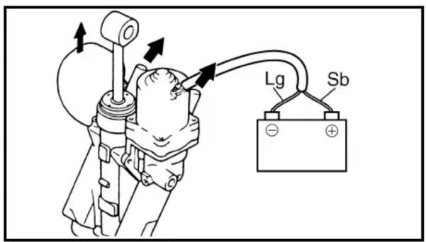
(10) After measuring the hydraulic pressure, connect the leads on the battery terminals in the up position until the power trim and tilt ram assemblies are fully extended.
(11) Remove the special tools.
(12) Install the manual valve and circlip.
NOTE:
After measuring the hydraulic pressure, bleed the power trim and tilt unit.
BRKT

| Order | Job/Part Q'ty Remarks | ||
| Reservoir and power trim and tilt motor1 Manual valve 12 Tilt ram end screw 13 Tilt ram assembly 14 O-ring 25 Bolt 36 Gear pump unit 1 | Refer to “RESERVOIR AND POWER TRIM AND TILT MOTOR” on page 7-33.Continued on next page. |
ENSEMBLE DE VERIN D'INCLINAISON ET UNITE DE POMPE A ENGRENAGES
DEPOSE/INSTALLATION DE L'ENSEMBLE DU VERIN D'INCLINAISON ET DE L'UNITE DE POMPE A ENGRENAGES
| Order | Job/Part Q'ty Remarks | ||
| 7 | Check valve assembly 1 | ||
| 8 | Gear pump 1 | ||
| 9 | Shuttle valve 2 | ||
| 10 | Check valve 2 | ||
| 11 | Up-relief valve assembly 1 | ||
| 12 | Down-relief valve assembly 1 | ||
| For installation, reverse the removal procedure. |
natural_image
Technical line drawing of a mechanical assembly with gears and shafts (no text or symbols)
REMOVING THE TILT RAM END SCREW
Loosen:
- Tilt ram end screw

End screw wrench YB-06548 / 90890-06548
NOTE:
Hold the power trim and tilt unit in a vise using aluminum plates on both sides.
REMOVING THE GEAR PUMP UNIT
Remove:
- Bolt ①
- Gear pump unit ②
- O-ring ③
- Check valve ④
NOTE:
Place a container under the power trim and tilt unit.
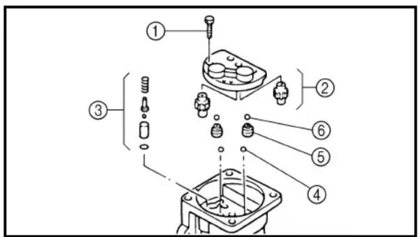
DISASSEMBLING THE GEAR PUMP UNIT
-
Remove:
-
Bolt ①
- Pump gear ②
- Up-relief valve assembly ③
- Ball (4.76 mm/0.187 in) ④
- Shuttle valve ⑤
- Ball (3.18 mm/0.125 in) ⑥
NOTE:
When removing the pump gears, note their original direction and position for proper assembly.
BRKT

DEPOSE DE LA VIS CAPUCHON DU VERIN D'INCLINAISON
Desserrer:
2. Remove:
- Check valves ① and ②
NOTE:
To remove the check valves, cover the gear pump housing with a clean cloth and then blow compressed air through holes ⓐ and ⓑ .
CHECKING THE TILT RAM
Check:
- Tilt ram
Excessive scratches → Replace.
Bends/excessive corrosion → Replace.
Rust → Polish.
(with 400 - 600 grit sandpaper)

CHECKING THE GEAR PUMP UNIT
Check:
- Shuttle valves ①
- Check valve assemblies ②
Clogs/damage/wear → Replace. - Pump gears ③
Damage/wear → Replace the gear pump unit. - Up-relief valve assembly ④
- Down-relief valve assembly ⑤
Damage/wear → Replace the gear pump unit. - Balls ⑥
Damage/wear → Replace.
BRKT

2. Déposer:
- Clapets antiretour ① et ②
N.B.:
Install all components in their original direction and position for proper assembly and operation.
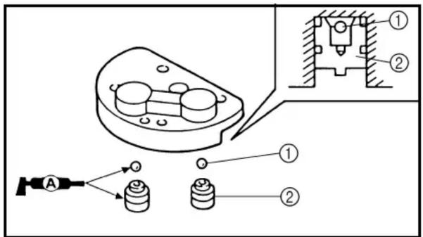


1. Install:
- Balls (3.18 mm/0.125 in) ①
- Shuttle valves ②
NOTE: \_\_\_\_
Apply grease to the balls to prevent them from falling out of the gear pump.
2. Install:
- O-ring ①
- Ball (3.18 mm/0.125 in) ②
- Up-relief valve pin ③
- Spring ④
- Up-relief valve ⑤
- Up-relief valve assembly ⑥
3. Install:
- O-rings ①
- Check valves ②
- Balls (4.76 mm/0.187 in) ③
- Pump gears ④
4. Install:
- Gear pump ①
- Bolt ②
- Filter ③
- O-ring ④
- Down-relief valve ⑤
- Filter ⑥
NOTE: \_\_\_\_
Tighten the bolts evenly and make sure the pump gears turn smoothly.
MONTAGE DE L'UNITE DE LA POMPE A ENGRENAGES
ATTENTION:
INSTALLING THE GEAR PUMP UNIT
-
Install:
-
O-rings ①
- Ball ②
- Pin ③
- Check valve ④
- Check valve assembly ⑤
NOTE:
When installing the check valve assembly, make sure the pin is on the tilt ram cylinder side as shown.
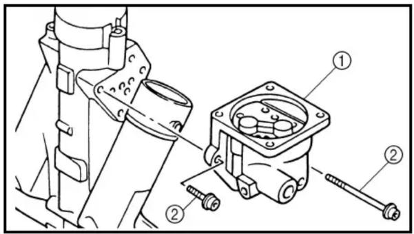
-
Install:
-
Gear pump unit ①
- Bolt ②
INSTALLING THE TILT RAM ASSEMBLY
WARNING
To prevent the hydraulic fluid from spurting out due to internal pressure, the tilt ram should be kept at full length.
- Fill:
- Tilt ram cylinder

natural_image
Technical line drawing of a mechanical device with gears and shafts (no text or symbols)
Recommended power trim and tilt fluid ATF Dexron II
NOTE:
Hold the power trim and tilt unit in a vise using aluminum plates on both sides.
BRKT

INSTALLATION DE L'UNITE DE LA POMPE A ENGRENAGES
1. Installer:
- Joints toriques ①
• Bille ②
• Goupille ③ - Clapet antiretour ④
- Ensemble de clapet antiretour ⑤
N.B.:
2. Fill:
- Gear pump housing

Recommended power trim and tilt fluid ATF Dexron II
NOTE:
Add power trim and tilt fluid through the hole ⓐ until the fluid level is to the top of the gear pump unit.

natural_image
Technical line drawing of a mechanical assembly with piston and housing components (no text or labels)3. Install:
- Tilt ram assembly
NOTE:
Place the tilt ram end screw at the bottom of the tilt ram and install the tilt ram assembly into the tilt ram cylinder.

natural_image
Technical line drawing of a mechanical assembly with gears and shafts (no text or symbols)4. Tighten:
- Tilt ram end screw

End screw wrench YB-06548 / 90890-06548

Tilt ram end screw 130 Nm (13 m • kgf, 94 ft • lb)
BRKT

2. Remplir:
| Order | Job/Part Q'ty Remarks | ||
| Tilt ram assembly and gear pump unit1 Trim ram end screw 22 Trim ram 23 O-ring 24 Seal ring 25 Free piston 16 O-ring 17 Piston ring 1 | Refer to “TILT RAM ASSEMBLY AND GEAR PUMP UNIT” on page 7-41.For installation, reverse the removal procedure. |
ENSEMBLES DU VERIN D'ASSIETTE ET PISTON LIBRE
DEPOSE/INSTALLATION DES ENSEMBLES DU VERIN D'ASSIETTE ET DU PISTON LIBRE
natural_image
Technical line drawing showing two mechanical assembly steps (A and B) with no visible text or symbols

REMOVING THE TRIM RAM END SCREWS
Loosen:
- Trim ram end screw

End screw wrench YB-06175-1A / 90890-06548
A For USA and Canada
B For worldwide
NOTE: ____
Hold the power trim and tilt unit in a vise using aluminum plates on both sides.
REMOVING THE FREE PISTON
- Drain:
• Power trim and tilt fluid
NOTE: ____
After removing the trim ram assemblies, drain the fluid from the power trim and tilt unit.
- Install:
- Trim ram assemblies ①
NOTE: ____
Finger-tighten the trim ram assemblies and then cover the tilt cylinder openings with a clean cloth.
- Remove:
- Free piston ②
WARNING
Never look into the tilt cylinder opening because the free piston and hydraulic fluid may be expelled out forcefully.
NOTE:
Remove the free piston by blowing compressed air through the hole ⓐ.
BRKT

ENSEMBLES DU VERIN D'ASSIETTE ET PISTON LIBRE
CHECKING THE TRIM RAMS
Check:
- Trim ram
Excessive scratches → Replace.
Bends/excessive corrosion → Replace.
Rust → Polish.
(with 400 - 600 grit sandpaper)
CHECKING THE FREE PISTON
Check:
- Free piston
Excessive scratches → Replace.
CHECKING THE TRIM RAM CYLINDERS
Check:
- Trim ram cylinder
Cracks/excessive scratches → Replace the power trim and tilt unit.
INSTALLING THE FREE PISTON
- Fill:
- Fluid passages

Recommended power trim and tilt fluid
ATF Dexron II
Quantity
30 cm ^3 (1.0 US oz, 1.1 Imp oz)
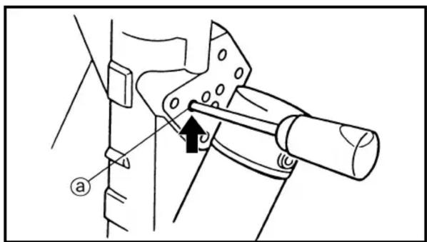
NOTE:
- Hold the power trim and tilt unit in a vise using aluminum plates on both sides.
- Add power trim and tilt fluid through the hole ⓐ.
VERIFICATION DES VERINS D'ASSIETTE
Vérifier:

natural_image
Line drawing of a mechanical device with two ports and a lever (no text or symbols)
2. Install:
- Piston ring ①
- O-ring ②
- Free piston ③
NOTE: ____
Push the free piston into the tilt ram cylinder until it bottoms out.
INSTALLING THE TRIM RAMS

WARNING
Do not push the trim rams down while installing them into the trim ram cylinders. Otherwise, the hydraulic fluid may spurt out from the unit.
1. Fill:
- Trim ram cylinders

Recommended power trim and tilt fluid ATF Dexron II
NOTE:
Hold the power trim and tilt unit in a vise using aluminum plates on both sides.
2. Fill:
- Fluid passages

Recommended power trim and tilt fluid ATF Dexron II
NOTE:
Add power trim and tilt fluid through holes ⓐ, Ⓐ and Ⓒ until all of the passages are filled.
BRKT

ENSEMBLES DU VERIN D'ASSIETTE ET PISTON LIBRE

natural_image
Technical line drawings of mechanical components, showing two views (A and B) with no visible text or symbols.3. Install:
- Trim ram assemblies ①
NOTE:
Place each trim ram end screw at the bottom of each trim ram and install them into the trim ram cylinders.
4. Tighten:
- Trim ram end screw
| End screw wrench YB-06175-1A / 90890-06548 | |
| Trim ram end screw 80 Nm (8.0 m • kgf, 58 ft • lb) |
A For USA and Canada
B For worldwide
BRKT

ENSEMBLES DU VERIN D'ASSIETTE ET PISTON LIBRE
(8,0 m • kgf, 58 ft • lb)
(8,0 m · kgf, 58 ft · lb)
(Starboard view) 8-2
(Front view) 8-3
(Aft view) 8-4
(Top view)....8-5
WIRE HARNESS 8-6
ELECTRICAL COMPONENTS ANALYSIS 8-8
DIGITAL CIRCUIT TESTER.... 8-8
MEASURING THE PEAK VOLTAGE.... 8-8
PEAK VOLTAGE ADAPTOR.... 8-8
MEASURING A LOW RESISTANCE.... 8-9
IGNITION SYSTEM....8-10
CHECKING THE BATTERY 8-11
CHECKING THE FUSES 8-11
MEASURING THE IGNITION COIL ASSEMBLY.... 8-11
CHECKING THE IGNITION SPARK GAP 8-12
MEASURING THE IGNITION SYSTEM PEAK VOLTAGE 8-13
CHECKING THE FUSES 8-16
MEASURING THE PULSER COIL OUTPUT PEAK VOLTAGE...... 8-16
MEASURING THE ENGINE COOLING WATER TEMPERATURE SENSOR RESISTANCE 8-16
CHECKING THE OIL PRESSURE SWITCH CONTINUITY.... 8-17
MEASURING THE THROTTLE POSITION SENSOR 8-18
FUEL CONTROL SYSTEM....8-19
CHECKING THE BATTERY.... 8-20
CHECKING THE FUSES 8-20
MEASURING THE ENGINE COOLING WATER TEMPERATURE SENSOR RESISTANCE 8-20
MEASURING THE THROTTLE POSITION SENSOR 8-20
CHECKING THE FUEL INJECTORS.... 8-21
CHAPITRE 8 EQUIPEMENT ELECTRIQUE
(Vue de face).... 8-3
CHECKING THE BATTERY 8-23
CHECKING THE FUSES 8-23
CHECKING THE WIRE HARNESS CONTINUITY.... 8-23
CHECKING THE WIRE CONNECTIONS 8-23
CHECKING THE STARTER RELAY 8-23
CHECKING THE SHIFT POSITION SWITCH CONTINUITY...... 8-24
STARTER MOTOR 8-25
DISASSEMBLING/ASSEMBLING THE STARTER MOTOR...... 8-25
REMOVING THE STARTER MOTOR PINION 8-28
CHECKING THE STARTER MOTOR PINION 8-28
CHECKING THE ARMATURE 8-28
MEASURING THE BRUSHES.... 8-29
CHECKING THE MAGNETIC SWITCH RELAY.... 8-30
CHARGING SYSTEM 8-31
CHECKING THE FUSES 8-32
CHECKING THE BATTERY 8-32
MEASURING THE LIGHTING COIL OUTPUT PEAK VOLTAGE ...... 8-32
MEASURING THE RECTIFIER/REGULATOR OUTPUT
PEAK VOLTAGE 8-32
POWER TRIM AND TILT SYSTEM 8-33
CHECKING THE BATTERY 8-34
CHECKING THE POWER TRIM AND TILT RELAY.... 8-34
CHECKING THE TRAILER SWITCH CONTINUITY 8-35
MEASURING THE TRIM SENSOR RESISTANCE.... 8-35
POWER TRIM AND TILT MOTOR 8-36
DISASSEMBLING/ASSEMBLING THE POWER TRIM AND
TILT MOTOR....8-36
REMOVING THE STATOR 8-38
REMOVING THE BRUSH 8-38
CHECKING THE BRUSH 8-38
CHECKING THE ARMATURE 8-39
INSTALLING THE BRUSH 8-40
INSTALLING THE ARMATURE 8-40
INSTALLING THE STATOR 8-40
SYSTEME DE DEMARRAGE......8-22
VERIFICATION DE LA
BATTERIE 8-23
VERIFICATION DES FUSIBLES..8-23
INSPECTION DE LA CONTINUITE
DU FAISCEAU DE FILS......8-23
VERIFICATION DES
CONNEXIONS DE FIL ......8-23
VERIFICATION DU RELAIS
DE DEMARREUR 8-23
VERIFICATION DE LA CONTINUITE
DU CONTACTEUR DE POSITION
DE SELECTION 8-24
DEMARREUR 8-25
DEMONTAGE/MONTAGE DU
DEMARREUR 8-25
DEPOSE DU PIGNON DU
DEMARREUR 8-28
VERIFICATION DU PIGNON
DU DEMARREUR......8-28
VERIFICATION DE L'INDUIT....8-28
MESURE DES BALAIS......8-29
VERIFICATION DU RELAIS
DE COMMUTATEUR
MAGNETIQUE....8-30
SYSTEME DE CHARGE....8-31
VERIFICATION DES FUSIBLES..8-32
VERIFICATION DE LA
BATTERIE 8-32
MESURE DE LA TENSION DE
CRETE DE SORTIE DE LA
BOBINE D'ALLUMAGE......8-32
MESURE DE LA TENSION DE
CRETE DU REDRESSEUR/
REGULATEUR....8-32
SYSTEME D'ASSIETTE ET
D'INCLINAISON ASSISTEES .....8-33
VERIFICATION DE LA
BATTERIE 8-34
VERIFICATION DU RELAIS DU
SYSTEME D'ASSIETTE ET
D'INCLINAISON ASSISTEES ....8-34
VERIFICATION DE LA
CONTINUITE DU CONTACTEUR
DE REMORQUE.... 8-35
MESURE DE LA RESISTANCE
DU CAPTEUR D'ASSIETTE......8-35
MOTEUR DU SYSTEME
D'ASSIETTE ET D'INCLINAISON
ASSISTEES 8-36
DEMONTAGE/MONTAGE DU
MOTEUR DU SYSTEME
D'ASSIETTE ET D'INCLINAISON
ASSISTEES.... 8-36
DEPOSE DU STATOR 8-38
DEPOSE DU BALAI.... 8-38
VERIFICATION DU BALAI......8-38
VERIFICATION DE L'INDUIT....8-39
INSTALLATION DU BALAI......8-40
INSTALLATION DE L'INDUIT...8-40
INSTALLATION DU STATOR ....8-40
STARTERSYSTEM 8-22
ÜBERPRÜFUNG DER
BATTERIE 8-23
ÜBERPRÜFUNG DER
DE LOS CABLES....8-23
ESTIBADO MOTORIZADO E
DEL SENSOR DE ESTIBADO.....8-35
MOTOR DE ESTIBADO MOTORIZA-
① Oil pressure switch
② Throttle position sensor
③ Idle speed control valve
④ Intake air pressure sensor
⑤ Fuel injector
⑥ High-pressure fuel pump
COMPOSANTS ELECTRIQUES
(Vue bâbord)
① Ignition coil
② Engine cooling water temperature sensor
③ Starter motor
④ Relay (magnetic switch)
⑤ Battery lead terminal
⑥ Junction box assembly
(Vue tribord)
① Fuse (30A)
② Main relay
③ ECM
④ Rectifier/regulator
⑤ Intake air temperature sensor
⑥ Power trim and tilt relay
⑦ Starter relay
⑧ Fuse (20A)
(Vue de face)
① Spark plug
② Spark plug lead
(Vue arrière)
① Fuel injector
② Intake air pressure sensor
③ Idle speed control valve
④ Throttle position sensor
⑤ Trailer switch
⑥ Relay (magnetic switch)
⑦ Starter
⑧ Lighting coil
(Vue de dessus)
① Ground
② ECM
③ Ignition coil
④ Ignition coil
⑤ Engine cooling water temperature sensor
⑥ Remote control
⑦ Warning lamp
⑧ PTT relay
⑨ Starter relay
⑩ Main relay
⑪ Trailer switch
⑫ Starter relay
⑬ Rectifier/regulator
⑭ Starter motor
⑮ Fuse 20A
⑯ Fuse 30A

flowchart
graph TD
    A["③"] --> B["②"]
    B --> C["④"]
    C --> D["⑤"]
    D --> E["⑥"]
    E --> F["⑧"]
    F --> G["⑨"]
    G --> H["⑩"]
    H --> I["⑪"]
    I --> J["⑨"]
    J --> K["⑩"]
    K --> L["③"]

    subgraph Component_1
        M["W/B"] --> N["B"]
        O["W/R"] --> P["B"]
        Q["B"] --> R["B"]
        S["B"] --> T["B"]
        U["B"] --> V["B"]
        W["B"] --> X["B"]
        Y["R/Y"] --> Z["R/Y"]
        AA["R/Y"] --> AB["R/Y"]
        AC["R/Y"] --> AD["R/Y"]
        AE["P/W"] --> AF["P/W"]
        AG["O"] --> AH["O"]
        AI["P/G"] --> AJ["P"]
        AK["L"] --> AL["Pu/R"]
        AM["Pu/G"] --> AN["Pu/B"]
        AO["Pu/Y"] --> AP["R/Y"]
        AQ["G/R"] --> AR["G/B"]
        AS["G/Y"] --> AT["G/Y"]
        AU["B/Y"] --> AV["L/Y"]
        AW["P/W"] --> AX["W/B"]
        AY["W/R"] --> AZ["B"]
        BA["B"] --> BB["B"]
    end

    subgraph Component_2
        AC["③"] --> AD["②"]
    end

    style Component_1 fill:#f9f,stroke:#333
    style Component_2 fill:#f9f,stroke:#333
Connect to:
① Pulser coil
② ECM
③ Ground lead
④ Intake air temperature sensor
⑤ Oil pressure switch
⑥ Idle speed control valve
⑦ Throttle position sensor
⑧ Intake air pressure sensor
⑨ Fuel injectors
⑩ Shift position switch
⑪ High-pressure fuel pump
natural_image
Two types of multimeters shown side by side: one with a dial and the other with a rotary knob (no text or symbols)ELECTRICAL COMPONENTS ANALYSIS
DIGITAL CIRCUIT TESTER

Digital tester
J-39299 / 90890-06752
NOTE:
"○indicates a continuity of electricity which means a closed circuit at the respective switch position.
MEASURING THE PEAK VOLTAGE
NOTE:
- When checking the condition of the ignition system it is useful to know the peak voltage.
- Cranking speed is dependant on many factors (e.g., fouled or weak spark plugs, a weak battery). If one of these is defective, the peak voltage will be lower than specification.
- If the peak voltage measurement is not within specification the engine will not operate properly.
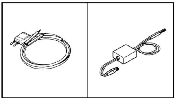
natural_image
Two technical line drawings of electrical components: a coiled cable and a rectangular device with wires (no text or symbols)PEAK VOLTAGE ADAPTOR
NOTE:
The peak voltage adaptor should be used with the digital circuit tester.

Peak voltage adaptor
YU-39991 / 90890-03169
ELEC
ANALYSE DES COMPOSANTS ELECTRIQUES TESTEUR NUMERIQUE


natural_image
Pure electrical circuit lines without any symbolsNOTE:
- When measuring the peak voltage, set the selector to the DC voltage mode.
- Make sure the peak voltage adaptor leads are properly installed in the digital tester.
- Make sure the positive pin (the “+” mark facing up as shown) on the peak voltage adaptor is installed into the positive terminal of the digital tester.
- The test harness is needed for the following tests.
Measuring steps
(1) Disconnect the coupler connections.
(2) Connect the test harness between the couplers.
(3) Connect the peak voltage adaptor probes to the connectors which are being checked.
(4) Start or crank the engine and observe the measurement.
MEASURING A LOW RESISTANCE
When measuring a resistance of 10 Ω or less with the digital tester, the correct measurement cannot be obtained because of the tester's internal resistance.
To obtain the correct value, subtract the internal resistance from the displayed measurement.

Correct value Displayed measurement – internal resistance
NOTE:
The internal resistance of the digital tester can be obtained by connecting both of its probes.
ELEC
N.B.:
① Spark plugs
② Ignition coils
③ Throttle position sensor (TPS)
④ Pulser coils
⑤ 10P coupler
⑥ ECM
⑦ Lighting coil
⑧ Rectifier/regulator
⑨ Battery
⑩ Fuse (30A)
B : Black
O : Orange
P : Pink
R : Red
W : White
B/R : Black/red
B/W : Black/white
R/Y : Red/yellow
W/B : White/black
W/R : White/red
SYSTEME D'ALLUMAGE
Refer to "CHECKING THE BATTERY" on page 3-21.
CHECKING THE FUSES
1. Check:
- Fuse holder continuity No continuity → Check the fuse holder leads.
2. Check:
- Fuse holder lead continuity No continuity Replace the fuse holder. Continuity Check the fuse.
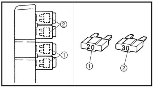

natural_image
Pure electrical circuit lines without any symbols3. Check:
- Fuse continuity No continuity → Replace.
- Fuse rating Out of specification → Replace.

Fuse rating
①: 12 V - 20 A
②: 12 V - 30 A
MEASURING THE IGNITION COIL ASSEMBLY
Measure:
- Ignition coil assembly resistance Out of specification → Replace.

Ignition coil assembly resistance
18.97 - 35.23 kΩ
(For cylinder No. 1, 4)
18.55 - 34.45 kΩ
(For cylinder No. 2, 3)
ELEC

VERIFICATION DE LA BATTERIE
Se reporter à “VERIFICATION DE LA BATTERIE” en page 3-21.
VERIFICATION DES FUSIBLES
1. Vérifier:
natural_image
Illustration of a hand operating a mechanical device with arrows indicating motion (no text or symbols)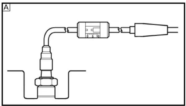

natural_image
Technical line drawing of a mechanical device with a close-up inset showing internal components (no text or symbols)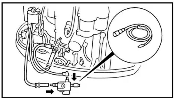
natural_image
Technical diagram of a mechanical assembly with hoses and tubing, showing a magnified inset of a cable connection (no text or labels)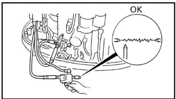
CHECKING THE IGNITION SPARK GAP
WARNING
- Do not touch any of the connections of the spark gap tester lead wires.
- Do not let sparks leak out of the removed spark plug cap.
- Keep flammable gas or liquids away, since this test can produce sparks.
Check:
- Ignition spark gap Above specification → Replace the spark plug. Below specification → Check the ECM output.
Ignition spark gap 1.0 - 1.1 mm (0.039 - 0.043 in)
A For USA and Canada
B For worldwide
Checking steps
(1) Remove the spark plugs from the engine.
(2) Connect a spark plug cap to the spark gap tester.
(3) Set the spark gap length on the adjusting knob.

Spark gap tester YM-34487 / 90890-06754
(4) Crank the engine and observe the spark through the discharge window of the spark gap tester.
ELEC
VERIFICATION DE LA LONGUEUR D'ETINCELLE
! AVERTISSEMENT
When checking the peak voltage do not touch any of the connections of the digital tester lead wires.
NOTE:
- If there is no spark or the spark is weak, continue with the ignition system test.
- If a good spark is obtained, the problem is not with the ignition system, but possibly with the spark plug(s) or another component.

1. Measure:
NOTE:
- The peak voltage adaptor should be used with the digital circuit tester.
- When measuring the peak voltage, set the selector to the DC voltage mode.

Peak voltage adaptor YU-39991 / 90890-03169
- ECM unit output peak voltage Below specification → Check the wire harness. Correct the wire harness → Replace the ECM unit.
| ECM unit output peak voltageBlack/red (B/R) – GroundBlack/white (B/W) – Ground | ||||
| r/min | Circuit Loaded | |||
| Cranking 1,500 | 0 3,500 | |||
| V 5.0 | 122 242 | 245 | ||
| Test harness (2-pin)90890-06792 |
MESURE DE LA TENSION DE CRETE DU SYSTEME D'ALLUMAGE
AVERTISSEMENT
- Pulser coil output peak voltage Below specification → Replace the pulser coil.
| Pulser coil output peak voltageWhite/black (W/B) – Black (B)White/red (W/R) – Black (B) | ||||
| r/min | Circuit Loaded | |||
| Cranking 1,500 | 0 3,500 | |||
| V 3.5 | 3.0 26 44 | |||
| Test harness (3-pin)90890-06791 |
2. Mesurer:
| 2017 | 2016 | |
| Cost of sales | 3.4 | 3.5 |
| Gross profit | (1.8) | (1.9) |
① ECM
② Engine cooling water temperature sensor
③ Oil pressure switch
④ Pulser coils
⑤ Throttle position sensor (TPS)
⑥ Main relay
⑦ Battery
⑧ Fuse (30A)
B : Black
O : Orange
P : Pink
R : Red
B/Y : Black/yellow
P/W : Pink/white
R/Y : Red/yellow
W/B : White/black
W/R : White/red
SYSTEME DE COM- MANDE D'ALLUMAGE
Refer to "CHECKING THE BATTERY" on page 3-21.
CHECKING THE FUSES
Refer to "CHECKING THE FUSES" on page 8-11.
MEASURING THE PULSER COIL OUTPUT PEAK VOLTAGE
Refer to "MEASURING THE IGNITION SYSTEM PEAK VOLTAGE" on page 8-13.
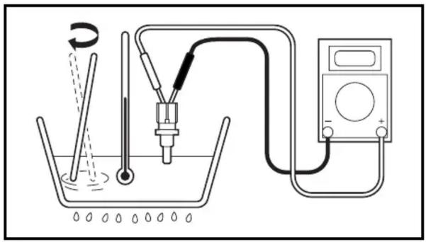
MEASURING THE ENGINE COOLING WATER TEMPERATURE SENSOR RESISTANCE
Measure:
- Engine cooling water temperature sensor resistance Out of specification → Replace.

Engine cooling water temperature sensor resistance Black/yellow (B/Y) – Black (B) 5 °C (41 °F): 4.62 kΩ 20 °C (68 °F): 2.44 kΩ 100 °C (212 °F): 0.19 kΩ
Measuring steps
(1) Place the engine cooling water temperature sensor in a container filled with water.
(2) Place a thermometer in the water.
(3) Slowly heat the water.
(4) Measure the resistance when the specified temperature is reached.
ELEC
VERIFICATION DE LA BATTERIE
Se reporter à “VERIFICATION DE LA BATTERIE” en page 3-21.
VERIFICATION DES FUSIBLES
CHECKING THE OIL PRESSURE SWITCH CONTINUITY
Measure:
- Oil pressure switch continuity Out of specification → Replace.

Mity vac YB-35956 / 90890-06756

Oil pressure switch continuity pressure 150 kPa (1.5 kg/cm ^2 , 21.33 psi) and below
ELEC
SYSTEME DE COMMANDE D'ALLUMAGE
ZÜNDSTEUERSYSTEM
SISTEMA DE CONTROL DEL ENCENDIDO
F
D
ES
VERIFICATION DE LA
CONTINUITE DU
MANOCONTACT D'HUILE
Mesurer:
When measuring the output voltage, set the selector to the DC voltage mode.
Measure:
- Throttle position sensor output voltage
Out of specification → Adjust the throttle position sensor.
Refer to "ADJUSTING THE THROTTLE POSITION SENSOR" on page 3-7.

Throttle position sensor output voltage
Pink (P) - Black (B)
0.732 ± 0.014 V
Measuring steps
(1) Connect the test harness (3-pin) as shown.

Test harness (3-pin) 90890-06793
(2) Connect the battery leads to a 12-V battery.
(3) Turn the engine switch to the on position.
(4) Measure the throttle position sensor output voltage.
(5) Start the engine and measure the output voltage again.
NOTE:
Make sure the throttle position sensor output voltage is within specification when the throttle is fully closed and fully opened.
ELEC

MESURE DU CAPTEUR DE POSITION D'ACCELERATEUR
N.B.:
① Fuel injectors
② Joint connector
③ Throttle position sensor
④ High-pressure fuel pump
⑤ Pulser coil
⑥ 10P connector
⑦ ECM
⑧ Main relay
⑨ Fuse (30A)
⑩ Fuse (20A)
⑪ Battery
⑫ Engine cooling water temperature sensor
⑬ Intake air pressure sensor
⑭ Intake air temperature sensor
⑮ Idle speed control valve
B : Black
G : Green
L : Blue
O : Orange
P : Pink
R : Red
Y: Yellow
B/Y : Black/yellow
G/R : Green/red
Refer to "CHECKING THE BATTERY" on page 3-21.
CHECKING THE FUSES
Refer to "CHECKING THE FUSES" on page 8-11.
MEASURING THE ENGINE COOLING WATER TEMPERATURE SENSOR RESISTANCE
Refer to "MEASURING THE ENGINE COOLING WATER TEMPERATURE SENSOR RESISTANCE" on page 8-16.
MEASURING THE THROTTLE POSITION SENSOR
Refer to "MEASURING THE THROT-TLE POSITION SENSOR" on page 8-18.
VERIFICATION DE LA BATTERIE
Se reporter à “VERIFICATION DE LA BATTERIE” en page 3-21.
VERIFICATION DES FUSIBLES

CHECKING THE FUEL INJECTORS
1. Check:
- Fuel injector operating sound No sound (no fuel is being sprayed) → Check the high-pressure fuel pump.
Checking steps
(1) Start the engine.
(2) Fully close the throttle valves.
(3) Attach the screwdriver ① onto the fuel injector body and check if all of the fuel injectors have a solenoid valve operating sound.
2. Check:
• High-pressure fuel pump operating sound
Correct → Replace the fuel injector (no sound).
No sound → Check the main relay.
NOTE: \_\_\_\_
- The high-pressure fuel pump should sound when the engine start switch is turned on.
- Disconnect the Brown (Br) starter relay lead ① to prevent the engine from starting.
3. Check:
- Main relay continuity Out of specification → Replace the main relay.
| Engine start switch | Lead color | ||
| Red (R) | Red/yellow (R/Y) | ||
| OFF | |||
| ON | ○ | ○ | |
Correct → Replace the high-pressure fuel pump.
VERIFICATION DES INJECTEURS DE CARBURANT
1. Vérifier:
① Fuse (30A)
② 10P connector
③ Starter relay
④ Battery
⑤ Relay (magnetic switch)
⑥ Starter motor
B : Black
Br : Brown
R : Red
Br/W : Brown/white
SYSTEME DE
DEMARRAGE
Refer to "CHECKING THE BATTERY" on page 3-21.
CHECKING THE FUSES
Refer to "CHECKING THE FUSES" on page 8-11.
CHECKING THE WIRE HARNESS CONTINUITY
Check:
- Wire harness continuity No continuity → Replace.
CHECKING THE WIRE CONNECTIONS
Check:
- Wire connections Poor connection → Properly connect.
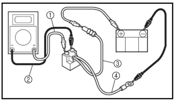
CHECKING THE STARTER RELAY
Check:
- Starter relay continuity No continuity → Replace.
Checking steps
(1) Connect the tester and battery between the starter relay terminals.
Positive digital tester probe ① → Starter relay terminal Negative digital tester probe ② – Starter relay terminal Positive battery terminal → Brown lead ③ Negative battery terminal → Black lead ④
(2) Check that there is continuity between the starter relay terminals.
ELEC
VERIFICATION DE LA BATTERIE
Se reporter à “VERIFICATION DE LA BATTERIE” en page 3-21.
VERIFICATION DES FUSIBLES
CHECKING THE SHIFT POSITION SWITCH CONTINUITY
Check:
- Continuity
No continuity → Replace.
| Switch position | Lead color | ||
| Blue/Yellow (L/Y) | Black (B) | ||
| a | Home position | ||
| b | Depressed | ○ | ○ |
VERIFICATION DE LA CONTINUITE DU CONTACTEUR DE POSITION DE SELECTION
Vérifier:
- Continuité
| Order | Job/Part Q'ty Remarks | ||
| Starter motor Refer to “IGNITION COILS AND STARTER MOTOR” on page 5-14. | |||
| 1 Nut 12 Bolt 23 Relay (magnetic switch) 14 Rubber dust 15 Spring 16 Starter motor pinion clip 17 Starter motor pinion stopper 18 Starter motor pinion 19 Spring 1Continued on next page. | |||
DEMARREUR
DEMONTAGE/MONTAGE DU DEMARREUR
| Order | Job/Part Q'ty Remarks | ||
| 10 | Bolt 2 | ||
| 11 | Screw 2 | ||
| 12 | Yoke assembly 1 | ||
| 13 | Rear cover 1 | ||
| 14 | Thrust washer 1 | ||
| 15 | Plate 1 | ||
| 16 | Brush holder assembly 1 | ||
| 17 | Brush assembly 1 | ||
| 18 | Armature 1 | ||
| 19 | Center bracket plate 1 | ||
| Continued on next page. |
| Order | Job/Part Q'ty Remarks | ||
| 20 | Shift lever 1 | ||
| 21 | Outer ring gear 1 | ||
| 22 | Planetary gear 3 | ||
| 23 | E-ring 1 | ||
| 24 | Pinion shaft 1 | ||
| 25 | Center bracket 1 | ||
| 26 | Thrust washer 1 | ||
| 27 | Clutch assembly 1 | ||
| 28 | Bearing 1 | ||
| 29 | Housing 1 | ||
| For assembly, reverse the disassembly procedure. |
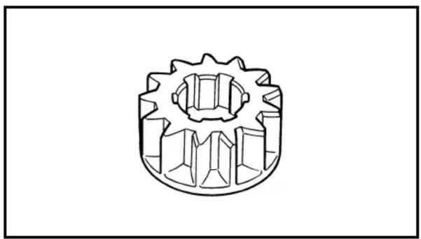
natural_image
Technical line drawing of a mechanical gear or sprocket component (no text or symbols)
natural_image
Technical line drawing of a mechanical component with no visible text or symbols
natural_image
Line drawing of hands operating a mechanical clamp or clamping device (no text or symbols present)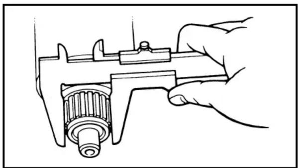
natural_image
Line drawing of a hand using a caliper to measure a mechanical component (no text or symbols present)REMOVING THE STARTER MOTOR PINION
Remove:
- Clips ①
NOTE:
Slide the pinion gear down as shown and then remove the clips ① with a thin screw driver.
CHECKING THE STARTER MOTOR PINION
- Check:
- Starter motor pinion teeth Damage/wear → Replace.
- Check:
- Starter motor pinion movement Incorrect → Replace.
NOTE: ____
Rotate the starter motor pinion counterclockwise and make sure it moves smoothly. Also, rotate the starter motor pinion clockwise and make sure it locks.
CHECKING THE ARMATURE
- Check:
- Commutator Foreign matter → Clean. (with 600 grit sandpaper)
- Measure:
- Commutator diameter Out of specification → Replace.

Commutator diameter limit 28.0 mm (1.10 in)
ELEC

DEPOSE DU PIGNON DU DEMARREUR
Déposer:
- Agrafes ①
N.B.:
natural_image
Line drawing of a hand using a tool to adjust a mechanical component (no text or symbols)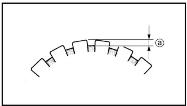

3. Check:
- Commutator undercut Dirt/foreign matter → Clean. (with compressed air)
4. Measure:
- Commutator undercut ⓐ Out of specification → Replace the armature.

Commutator undercut limit 0.2 mm (0.01 in)
5. Check:
- Armature continuity Out of specification → Replace.
| Armature continuity | ||
| Commutator segments a | Continuity | |
| Segment - Armature core b | No continuity | |
| Segment - Armature shaft c | No continuity | |

MEASURING THE BRUSHES
1. Measure:
- Brush length Out of specification → Replace the brush assembly.

Brush length limit ⓐ 9.5 mm (0.37 in)
ELEC

DEMARREUR
STARTERMOTOR
MOTOR DE ARRANQUE
3. Vérifier:

2. Check:
- Brush assembly continuity Out of specification → Replace the brush assembly.
 | Brush assembly continuity | |
| Brush 1 – Brush 2 | No continuity | |
CHECKING THE MAGNETIC SWITCH RELAY
Check:
- Magnetic switch relay continuity Out of specification → Replace.
Checking steps
(1) Remove the terminal ① from the magnetic switch relay.
NOTE: ____
Remove the terminal to prevent the pinion gear from turning.
(2) Connect the tester leads between the magnetic switch relay terminals as shown.
(3) Connect the Brown/white (Br/W) lead to the positive battery terminal.
(4) Connect the starter motor body to the negative battery terminal.
CAUTION:
Do not connect the battery for more than one second. Otherwise, the magnetic switch relay may be damaged.
(5) Check that there is continuity between the magnetic switch relay terminals.
(6) Check that there is no continuity after the Br/W lead is removed.
NOTE:
The starter motor pinion should be pushed out while the magnetic switch is on.
(7) Install the terminal to the magnetic switch relay.
2. Vérifier:
① Stator coil
② Rectifier/regulator
③ Fuse (30A)
④ Battery
B : Black
R : Red
W : White
SYSTEME DE CHARGE
Refer to "CHECKING THE FUSES" on page 8-11.
CHECKING THE BATTERY
Refer to "CHECKING THE BATTERY" on page 3-21.
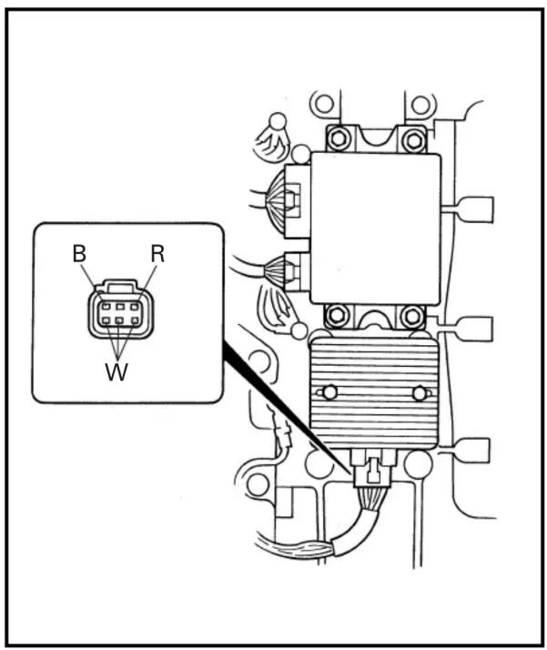

MEASURING THE LIGHTING COIL OUTPUT PEAK VOLTAGE
Measure:
- Lighting coil output peak voltage Measure with the rectifier/regulator output wire (red) disconnected. Below specification → Replace the lighting coil.
| Lighting coil output peak voltage White (W) – White (W) | ||||
| r/min | Circuit Loaded Circuit | |||
| Cranking 1,500 3,500 | ||||
| V 9.3 7.4 37 89 | ||||
| Test harness (6-pin)90890-06790 |
MEASURING THE RECTIFIER/ REGULATOR OUTPUT PEAK VOLTAGE
Measure:
- Rectifier/regulator output peak voltage Below specification → Replace the rectifier/regulator.
| Rectifier/regulator output peak voltageRed (R) – Black (B) | ||||
| r/min | Circuit Loaded | |||
| Cranking 1,500 | 3,500 | |||
| V — | — 12.5 13.0 | |||
| Test harness (6-pin)90890-06790 |
VERIFICATION DES FUSIBLES
Se reporter à "VERIFICATION
DES FUSIBLES" en page 8-11.
VERIFICATION DE LA BATTERIE
Se reporter à “VERIFICATION DE LA BATTERIE” en page 3-21.
MESURE DE LA TENSION DE CRETE DE SORTIE DE LA BOBINE D'ALLUMAGE
Mesurer:
① Power trim and tilt motor
② Trailer switch
③ 10P connector
④ Trim sensor
⑤ Battery
⑥ Power trim and tilt relay
A To remote control
B To trim meter
B : Black
Br : Brown
Gy : Gray
Lg : Light green
O : Orange
P : Pink
R : Red
Sb : Sky blue
R/W : Red/white
P/B : Pink/black
SYSTEME D'ASSIETTE ET D'INCLINAISON
ASSISTEES
Refer to "CHECKING THE BATTERY" on page 3-21.


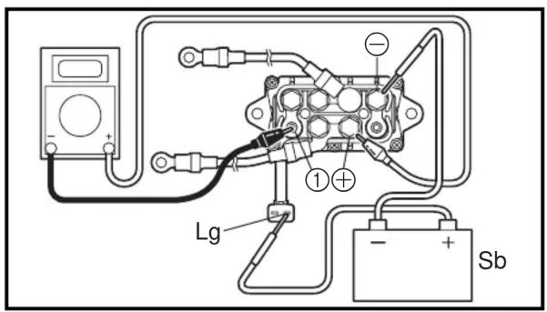

CHECKING THE POWER TRIM AND TILT RELAY
1. Check:
- Power trim and tilt relay continuity Out of specification → Replace.
| Power trim and tilt relay continuity | ||
| Sky blue (Sb) – Black (B)Light green (Lg) – Black (B) | Continuity | |
| Terminal 1 – Terminal ⊖Terminal 2 – Terminal ⊖ | Continuity | |
| Terminal 1 – Terminal ⊕Terminal 2 – Terminal ⊕ | No continuity | |
2. Check:
- Power trim and tilt relay operation No continuity → Replace.
Checking steps
(1) Connect the digital tester between power trim and tilt relay terminals ① and ⊕.
(2) Connect a 12-V battery as shown.
Light green (Lg) lead → Positive terminal Terminal ⊖ → Negative terminal
(3) Check that there is continuity between the power trim and tilt relay terminals.
(4) Connect the digital tester between power trim and tilt relay terminals and ② .
(5) Connect a 12-V battery as shown.
Sky blue (Sb) lead → Positive terminal Terminal ⊖ → Negative terminal
(6) Check that there is continuity between the power trim and tilt relay terminals.
ELEC

SYSTEME D'ASSIETTE ET D'INCLINAISON ASSISTEES
SERVO-TRIMM UND KIPPSYSTEM
ESTIBADO MOTORIZADO E
INCLINACIÓN
1. Compruebe:
- Trailer switch continuity
Out of specification → Replace.
 | Switch position | Lead color | ||
| Skyblue (Sb) | Red (R) | Light green (Lg) | ||
| Up | ||||
| Free | ||||
| Down | ||||

MEASURING THE TRIM SENSOR RESISTANCE
Measure:
- Trim sensor resistance
Out of specification → Replace.

Trim sensor resistance
Pink (P) – Black (B)
582 - 873 Ω at 20 °C (68 °F)
Orange (O) - Black (B)
800 - 1,200 Ω at 20 °C (68 °F)
NOTE:
Turn the lever ① and measure the resistance as it gradually changes.
VERIFICATION DE LA CONTINUITE DU CONTACTEUR DE REMORQUE
Vérifier:
| Order | Job/Part Q'ty Remarks | ||
| Power trim and tilt motor Refer to | "RESERVOIR AND POWER TRIMAND TILT MOTOR" on page 7-33. | ||
| 1 Screw 12 Lead holder 13 Screw 24 Stator 15 Armature 16 O-ring 17 Screw 2 | |||
| Continued on next page. | |||
MOTEUR DU SYSTEME D'ASSIETTE ET D'INCLINAISON ASSISTEES
DEMONTAGE/MONTAGE DU MOTEUR DU SYSTEME D'ASSIETTE ET D'INCLINAISON ASSISTEES
REMOVING THE STATOR
Remove:
- Stator ①
CAUTION:
- Keep the power trim and tilt motor leads inside the stator.
- Do not allow grease or oil to contact the commutator.
NOTE:
- Remove the lead holder ② and rubber spacer ③ from the stator and slide them towards the leads.
- Hold the end of the armature shaft with a clean cloth and pull off the stator.
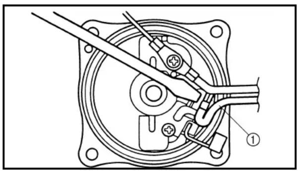
natural_image
Technical diagram of a mechanical assembly with labeled parts (no readable text or symbols)REMOVING THE BRUSH
- Remove:
- Sky blue power trim and tilt motor lead ①
NOTE:
Hold the brush with a screwdriver as shown. Then, disconnect the sky blue lead.

-
Remove:
-
Brush holders ①
- Brushes ②
CAUTION:
Do not touch the bimetal ⓐ; touching it may affect the operation of the breaker.

CHECKING THE BRUSH
- Measure:
- Brush length @ Out of specification → Replace.

Brush length 4.8 mm (0.19 in)
DEPOSE DU STATOR
Déposer:
- Stator ①
ATTENTION:
natural_image
Diagram of a mechanical or electrical component with two wires and a connector, no text or symbols present
natural_image
Technical line drawing of a mechanical gear assembly with shaft and housing (no text or symbols)

natural_image
Illustration of hands using a tool to adjust or install a mechanical component (no text or symbols visible)
natural_image
Illustration of hands using a screwdriver to adjust a mechanical component (no text or symbols present)2. Check:
- Brush continuity
No continuity → Replace.
CAUTION:
Do not touch the bimetal ⓐ; touching it may affect the operation of the breaker.
CHECKING THE ARMATURE
1. Measure:
- Commutator diameter ⓐ
Out of specification → Replace.

Commutator diameter limit 21.0 mm (0.83 in)
2. Measure:
- Commutator undercut ⓐ
Out of specification → Replace the armature.

Commutator undercut limit 0.85 mm (0.03 in)
3. Check:
- Armature continuity
Out of specification → Replace.
 | Armature continuity | |
| Commutator segments Continuity | ||
| Segment-laminations No continuity | ||
| Segment-shaft No continuity | ||
ELEC
MOTEUR DU SYSTEME D'ASSIETTE ET D'INCLINAISON ASSISTEES
SERVO-TRIMM UND KIPPMOTOR
INSTALLING THE BRUSH
Install:
- Brushes ①
- Brush holders ②
• Power trim and tilt motor leads ③ - Screw ④
CAUTION:
Do not touch the bimetal; touching it may affect the operation of the breaker.

INSTALLING THE ARMATURE
Install:
- Armature ①
NOTE:
Push the brushes into the holder and then install the armature.
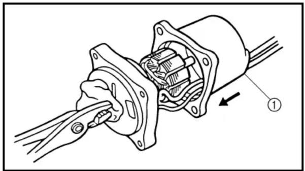
natural_image
Mechanical assembly diagram showing a motor and gear assembly with no visible text or symbolsINSTALLING THE STATOR
Install:
- Stator ①
NOTE:
Place a clean cloth over the end of the armature shaft and carefully push the armature into the stator with a pair of pliers as shown.
ELEC
MOTEUR DU SYSTEME D'ASSIETTE ET D'INCLINAISON ASSISTEES
SERVO-TRIMM UND KIPPMOTOR
DIAGNOSIS CODE INDICATION 9-5
DIAGNOSIS THE ELECTRONIC CONTROL SYSTEM 9-5
TROUBLE SHOOTING FOR ELECTRIC FUEL INJECTION.... 9-7
CHAPITRE 9 DEPANNAGE
DEPANNAGE....9-1
TABLEAU DE DEPANNAGE .....9-1
AUTODIAGNOSTIC....9-5
INDICATION DU CODE DE
DIAGNOSTIC....9-5
DIAGNOSTIC DU SYSTEME DE
COMMANDE ELECTRONIQUE ..9-5
DEPANNAGE POUR
L'INJECTION DE CARBURANT
ELECTRIQUE....9-7
AUTODIAGNÓSTICO....9-5
DE COMBUSTIBLE ......9-7
TROUBLE ANALYSIS
NOTE:
The following items should be checked before the “TROUBLE ANALYSIS CHART” is consulted.
- The battery is charged and its specified gravity is within specification.
- There are no incorrect wiring connections.
- Wiring connections are properly secured and are not rusty.
- The lanyard is installed onto the engine stop switch.
- The shift position is in neutral.
- Fuel is reaching the vapor separator.
- The rigging and engine setting are correct.
- The engine is free from any "Hull problem".
TROUBLE ANALYSIS CHART
| Trouble mode Check elements | ||||||||||||||||||
| ENGINE WILL NOT START | HARD STARTING | ROUGH IDLING | HIGH IDLING | ENGINE STALLS | POOR ACCELERATION | ENGINE WILL NOT STOP | POOR PERFORMANCE | LIMITED ENGINE SPEED | OVERHEATING | LOW OIL PRESSURE | LOOSE STEERING | LOOSE TILT HOLDING | TILT MOTOR WILL NOT RUN | HARD SHIFTING | IRREGULAR WARNING INDICATION | POOR BATTERY CHARGING | Relative part | Reference chapter |
| FUEL SYSTEM | ||||||||||||||||||
| Low-pressure fuel line | ||||||||||||||||||
| ○ | ○ | ○ | ○ | ○ | ○ | ○ | • Fuel line 3 | |||||||||||
| ○ | ○ | ○ | ○ | ○ | ○ | ○ | • Fuel filter 3 | |||||||||||
| ○ | ○ | ○ | ○ | ○ | ○ | ○ | • Fuel pump 4 | |||||||||||
| High-pressure fuel line | ||||||||||||||||||
| ○ | ○ | ○ | ○ | ○ | ○ | ○ | • Vapor separator 4 | |||||||||||
| ○ | ○ | ○ | ○ | ○ | • High-pressure fuel pump | 4 | ||||||||||||
| ○ | ○ | ○ | ○ | ○ | ○ | ○ | • High-pressure fuel line 3 | |||||||||||
| ○ | ○ | ○ | ○ | ○ | ○ | ○ | • Fuel injectors 4 | |||||||||||
| ○ | ○ | ○ | ○ | Link adjustment 3 | ||||||||||||||
| Trouble mode | Check elements | ||||||||||||||||
| ENGINE WILL NOT START | HARD STARTING | ROUGH IDLING | HIGH IDLING | ENGINE STALLS | POOR ACCELERATION | ENGINE WILL NOT STOP | POOR PERFORMANCE | LIMITED ENGINE SPEED | OVERHEATING | LOW OIL PRESSURE | LOOSE STEERING | LOOSE TILT HOLDING | TILT MOTOR WILL NOT RUN | HARD SHIFTING | IRREGULAR WARNING INDICATION | POWER UNIT | Reference chapter |
| POWER UNIT | |||||||||||||||||
| ○ | ○ | ○ | ○ | ○ | ○ | ○ | Compression 3 | ||||||||||
| ○ | ○ | ○ | ○ | ○ | ○ | Cylinder head gaskets 5 | |||||||||||
| ○ | ○ | ○ | ○ | ○ | ○ | ○ | Cylinder block 5 | ||||||||||
| ○ | ○ | ○ | ○ | ○ | ○ | ○ | Crankcase 5 | ||||||||||
| ○ | ○ | ○ | ○ | ○ | ○ | ○ | Piston rings 5 | ||||||||||
| ○ | ○ | ○ | ○ | ○ | ○ | ○ | Pistons 5 | ||||||||||
| ○ | ○ | ○ | ○ | ○ | ○ | ○ | Bearings 5 | ||||||||||
| ○ | Thermostat 5 | ||||||||||||||||
| ○ | Water passages 5 | ||||||||||||||||
| ○ | ○ | ○ | ○ | Valve(s) and valve seat(s) | 5 | ||||||||||||
| ○ | ○ | Valve clearance adjusting shim(s) | 5 | ||||||||||||||
| ○ | ○ | ○ | Camshaft(s) 5 | ||||||||||||||
| ○ | ○ | ○ | Timing belt 5 | ||||||||||||||
| ○ | ○ | Oil pump 6 | |||||||||||||||
| ○ | • Engine oil 3 | ||||||||||||||||
| ○ | Oil filter 3 | ||||||||||||||||
| ○ | Oil pressure switch 8 | ||||||||||||||||
| LOWER UNIT | |||||||||||||||||
| ○ | ○ | ○ | Neutral position | 6 | |||||||||||||
| ○ | ○ | Dog clutch | 6 | ||||||||||||||
| ○ | ○ | ○ | Gears | 6 | |||||||||||||
| ○ | Water inlets 6 | ||||||||||||||||
| ○ | Water pump | 6 | |||||||||||||||
| ○ | Propeller shaft(s) | 6 | |||||||||||||||
| ○ | Shift rod joint/pin | 6 | |||||||||||||||
| ○ | Shift cam | 6 | |||||||||||||||
| ○ | Shift shaft 6 | ||||||||||||||||
| ○ | ○ | Lower case | 6 | ||||||||||||||
| Trouble mode Check elements | ||||||||||||||||||
| ENGINE WILL NOT START | HARD STARTING | ROUGH IDLING | HIGH IDLING | ENGINE STALLS | POOR ACCELERATION | ENGINE WILL NOT STOP | POOR PERFORMANCE | LIMITED ENGINE SPEED | OVERHEATING | LOW OIL PRESSURE | LOOSE STEERING | LOOSE TILT HOLDING | TILT MOTOR WILL NOT RUN | HARD SHIFTING | IRREGULAR WARNING INDICATION | POOR BATTERY CHARGING | Relative part | Reference chapter |
| BRACKET UNIT | ||||||||||||||||||
| ○ | Bracket 7 | |||||||||||||||||
| ○ | Rubber mount 7 | |||||||||||||||||
| ○ | Shift rod 7 | |||||||||||||||||
| POWER TRIM AND TILT UNIT | ||||||||||||||||||
| ○ | Fluid level 3 | |||||||||||||||||
| ○ | Relief valve 7 | |||||||||||||||||
| ○ | Fluid passages — | |||||||||||||||||
| ○ | Power trim and tilt motor 7 | |||||||||||||||||
| ELECTRICAL | ||||||||||||||||||
| Ignition system | ||||||||||||||||||
| ○ | ○ | ○ | ○ | ○ | ○ | • Pulser coils 8 | ||||||||||||
| ○ | ○ | ○ | ○ | ○ | • ECM 8 | |||||||||||||
| ○ | ○ | ○ | ○ | • Ignition coils 8 | ||||||||||||||
| ○ | ○ | ○ | ○ | ○ | ○ | ○ | ○ | • Spark plugs 3 | ||||||||||
| Ignition/fuel control system | ||||||||||||||||||
| ○ | ○ | • Lanyard switch — | ||||||||||||||||
| ○ | • Main relay 8 | |||||||||||||||||
| ○ | ○ | ○ | ○ | ○ | ○ | • High-pressure fuel pump resistor | 8 | |||||||||||
| ○ | ○ | ○ | • Intake aie pressure sensor | 8 | ||||||||||||||
| ○ | ○ | ○ | • Intake air temperature sensor | 8 | ||||||||||||||
| ○ | ○ | ○ | ○ | • Engine cooling water temperature sensor | 8 | |||||||||||||
| ○ | ○ | ○ | ○ | • Throttle position sensor | 8 | |||||||||||||
| ○ | ○ | • Idle speed control assembly | 4 | |||||||||||||||
| Starting system | ||||||||||||||||||
| ○ | ○ | ○ | • Engine start switch — | |||||||||||||||
| ○ | • Shift position switch 8 | |||||||||||||||||
| ○ | • Starter relay 8 | |||||||||||||||||
| ○ | • Starter motor 8 | |||||||||||||||||
| Charging system | ||||||||||||||||||
| ○ | • Lighting coil 8 | |||||||||||||||||
| ○ | • Rectifier/regulator 8 | |||||||||||||||||
| ○ | • Fuses 8 | |||||||||||||||||
| ○ | ○ | ○ | ○ | • Battery leads — | ||||||||||||||
| ○ | ○ | ○ | • Battery — | |||||||||||||||
| Power trim and tilt system | ||||||||||||||||||
| ○ | • Trailer switch 8 | |||||||||||||||||
| ○ | • Power trim and tilt relay | 8 | ||||||||||||||||
| ○ | • Trim sensor 8 | |||||||||||||||||


SELF-DIAGNOSIS DIAGNOSIS CODE INDICATION
1. Normal condition
(no defective part or irregular processing is found)
Single flash is given every 4.95 seconds.
Ⓐ : Light on, 0.33 second
(b) : Light off, 4.95 seconds
2. Trouble code indication
Example: The illustration indicates code number 23.
When performing this diagnosis, all of the electrical wires must be properly connected.
2. Check:
- Diagnosis code
Code 1 is indicated → Normal.
Code 13 - 29 indicated → Check the applicable parts.
Code 33 - 44 indicated → Replace the CDI unit.

Checking steps
(1) Start the engine and let it idle.
(2) Check the diagnostic indicator's flash pattern to determine if there are any malfunctions.
NOTE:
When more than one problem is detected, the diagnostic tester's light flashes in the pattern of the lowest numbered problem. After that problem is corrected, the light flashes in the pattern of the next lowest numbered problem. This continues until all of the problems are detected and corrected.
Diagnosis code chart
| Code Symptoms | |
| 13 | Incorrect pick-up coil input signal |
| 15 | Incorrect engine cooling water temperature sensor input signal |
| 18 | Incorrect throttle position sensor input signal |
| 19 | Incorrect battery positive voltage |
| 23 | Incorrect intake air temperature sensor input signal |
| 28 Incorrect shift position switch | |
| 29 | Incorrect intake air pressure sensor input signal (out of normal operating range) |
| 33 - 44 | Microcomputer processing information |
| (33) | Ignition timing is being slightly corrected (when starting a cold engine) |
| (37) Intake passage air leakage | |
| (44) | Engine stop switch control operating |
TROUBLE SHOOTING FOR ELECTRIC FUEL INJECTION
| Items Symptoms | |
| 1. Poor starting/Engine will not start | 1. No firing. The starter motor cranks the engine, but no firing is generated in the cylinder.2. The firing is generated in the cylinder, but the engine soon stops.3. Start-up time is too long. The engine will not start-up easily. |
| 1. Check the high-pressure fuel lines.1) Check for fuel line leaks↓2) Check the fuel pressure↓3) Check the operation of the fuel injector↓4) Check the diagnosis cord→Fuel pressure is out of specification→① Check the 20-A fuse→② Check the main relay→③ Check the high-pressure fuel pump operation→④ Check the main relay drive's ECM output→⑤ Check the pressure regulator | |
| 2. Check the ignition system.1) Check the wire harness↓2) Check the ignition spark↓3) Check the ignition coil↓4) Check the ECM output peak voltage↓5) Check the pulser coil output peak voltage | |
| Items Symptoms | |
| 2. Erratic idling speed | 1. The engine speed is not constant when idling.2. The engine stalls when the throttle lever is pulled back.3. The engine stalls when the throttle lever is opened or during outboard operation. |
| 1. Check the high-pressure fuel lines.1) Check for fuel line leaks↓2) Check the fuel pressure↓3) Check the operation of the fuel injector↓4) Check the diagnosis cord → Fuel pressure is out of specification→① Check the 20-A fuse→② Check the main relay→③ Check the high-pressure fuel pump operation→④ Check the pressure regulator | |
| 2. Check the ignition system.1) Check the wire harness↓2) Check the ignition spark↓3) Check the ignition coil↓4) Check the ECM output peak voltage↓5) Check the pulser coil output peak voltage | |
| 3. Check the ignition timing.1) Check the diagnosis cords→① Check the pulser coil diagnosis cord→② Check the engine cooling water temperature sensor diagnosis cord→③ Check the intake air temperature sensor diagnosis cord | |
| 3. Erratic engine speed | 1. The engine is started, but will not run smoothly. The engine speed drops during acceleration. |
| 1. Check the high-pressure fuel lines.1) Check for fuel line leaks↓2) Check the fuel pressure↓3) Check the operation of the fuel injector↓4) Check the diagnosis cord → Fuel pressure is out of specification→① Check the 20-A fuse→② Check the main relay→③ Check the high-pressure fuel pump operation→④ Check the main relay drive's ECM output→⑤ Check the pressure regulator | |
| 2. Check the ignition system.1) Check the wire harness↓2) Check the ignition spark↓3) Check the ignition coil↓4) Check the ECM output peak voltage↓5) Check the pulser coil output peak voltage | |
| 3. Check the ignition timing.1) Check the diagnosis cords→① Check the pulser coil diagnosis cord→② Check the engine cooling water temperature sensor diagnosis cord→③ Check the intake air temperature sensor diagnosis cord | |
DEPANNAGE
N.B.:
6Y5-83517-00 (soupape)
N.B.:
flowchart
graph TD
    subgraph Top_Lane
        A1["Engine cooling temperature sensor"] --> B1["Engine cooling temperature sensor"]
        B1 --> C1["Engine cooling temperature sensor"]
        C1 --> D1["Engine cooling temperature sensor"]
        D1 --> E1["Engine cooling temperature sensor"]
        E1 --> F1["Engine cooling temperature sensor"]
        F1 --> G1["Engine cooling temperature sensor"]
        G1 --> H1["Engine cooling temperature sensor"]
        H1 --> I1["Engine cooling temperature sensor"]
        I1 --> J1["Engine cooling temperature sensor"]
        J1 --> K1["Engine cooling temperature sensor"]
        K1 --> L1["Engine cooling temperature sensor"]
        L1 --> M1["Engine cooling temperature sensor"]
        M1 --> N1["Engine cooling temperature sensor"]
        N1 --> O1["Engine cooling temperature sensor"]
        O1 --> P1["Engine cooling temperature sensor"]
        P1 --> Q1["Engine cooling temperature sensor"]
        Q1 --> R1["Engine cooling temperature sensor"]
        R1 --> S1["Engine cooling temperature sensor"]
        S1 --> T1["Engine cooling temperature sensor"]
        T1 --> U1["Engine cooling temperature sensor"]
        U1 --> V1["Engine cooling temperature sensor"]
        V1 --> W1["Engine cooling temperature sensor"]
        W1 --> X1["Engine cooling temperature sensor"]
        X1 --> Y1["Engine cooling temperature sensor"]
        Y1 --> Z1["Engine cooling temperature sensor"]
        Z1 --> AA1["Engine cooling temperature sensor"]
        AA1 --> AB1["Engine cooling temperature sensor"]
        AB1 --> AC1["Engine cooling temperature sensor"]
        AC1 --> AD1["Engine cooling temperature sensor"]
        AD1 --> AE1["Engine cooling temperature sensor"]
        AE1 --> AF1["Engine cooling temperature sensor"]
        AF1 --> AG1["Engine cooling temperature sensor"]
        AG1 --> AH1["Engine cooling temperature sensor"]
        AH1 --> AI1["Engine cooling temperature sensor"]
        AI1 --> AJ1["Engine cooling temperature sensor"]
        AJ1 --> AK1["Engine cooling temperature sensor"]
        AK1 --> AL1["Engine cooling temperature sensor"]
        AL1 --> AM1["Engine cooling temperature sensor"]
        AM1 --> AN["Engine cooling temperature sensor"]
        AN --> AO["Engine cooling temperature sensor"]
        AO --> AP["Engine cooling temperature sensor"]
        AP --> AQ["Engine cooling temperature sensor"]
        AQ --> AR["Engine cooling temperature sensor"]
        AR --> AS["Engine cooling temperature sensor"]
        AS --> AT["Engine cooling temperature sensor"]
        AT --> AU["Engine cooling temperature sensor"]
        AU --> AV["Engine cooling temperature sensor"]
        AV --> AW["Engine cooling temperature sensor"]
        AW --> AX["Engine cooling temperature sensor"]
        AX --> AY["Engine cooling temperature sensor"]
        AY --> AZ["Engine cooling temperature sensor"]
        AZ --> BA["Engine cooling temperature sensor"]
        BA --> BB["Engine cooling temperature sensor"]
        BB --> BC["Engine cooling temperature sensor"]
        BC --> BD["Engine cooling temperature sensor"]
        BD --> BE["Engine cooling temperature sensor"]
        BE --> BF["Engine cooling temperature sensor"]
        BF --> BG["Engine cooling temperature sensor"]
        BG --> BH["Engine cooling temperature sensor"]
        BH --> BI["Engine cooling temperature sensor"]
        BI --> BJ["Engine cooling temperature sensor"]
        BJ --> BK["Engine cooling temperature sensor"]
        BK --> BL["Engine cooling temperature sensor"]
        BL --> BM["Engine cooling temperature sensor"]
        BM --> BN["Engine cooling temperature sensor"]
        BN --> BO["Engine cooling temperature sensor"]
        BO --> BP["Engine cooling temperature sensor"]
        BP --> BQ["Engine cooling temperature sensor"]
        BQ --> BR["Engine cooling temperature sensor"]
        BR --> BS["Engine cooling temperature sensor"]
        BS --> BT["Engine cooling temperature sensor"]
        BT --> BU["Engine cooling temperature sensor"]
        BU --> BV["Engine cooling temperature sensor"]
        BV --> BW["Engine cooling temperature sensor"]
        BW --> BX["Engine cooling temperature sensor"]
        BX --> BY["Engine cooling temperature sensor"]
        BY --> BZ["Engine cooling temperature sensor"]
        BZ --> CA["Engine cooling temperature sensor"]
        CA --> CB["Engine cooling temperature sensor"]
        CB --> CC["Engine cooling temperature sensor"]
        CC --> CD["Engine cooling temperature sensor"]
        CD --> CE["Engine cooling temperature sensor"]
        CE --> CF["Engine cooling temperature sensor"]
        CF --> CG["Engine cooling temperature sensor"]
        CG --> CH["Engine cooling temperature sensor"]
        CH --> CI["Engine cooling temperature sensor"]
        CI --> CJ["Engine cooling temperature sensor"]
        CJ --> CK["Engine cooling temperature sensor"]
        CK --> CR["Engine cooling temperature sensor"]
        CR --> CS["Engine cooling temperature sensor"]
        CS --> CT["Engine cooling temperature sensor"]
        CT --> CU["Engine cooling temperature sensor"]
        CU --> CV["Engine cooling temperature sensor"]
        CV --> CW["Engine cooling temperature sensor"]
        CW --> CX["Engine cooling temperature sensor"]
        CX --> CY["Engine cooling temperature sensor"]
        CY --> CZ["Engine cooling temperature sensor"]
        CZ --> DA["Engine cooling temperature sensor"]
        DA --> DB["Engine cooling temperature sensor"]
        DB --> DC["Engine cooling temperature sensor"]
        DC --> DD["Engine cooling temperature sensor"]
        DD --> DE["Engine cooling temperature sensor"]
        DE --> DF["Engine cooling temperature sensor"]
        DF --> DG["Engine cooling temperature sensor"]
        DG --> DH["Engine cooling temperature sensor"]
        DH --> DI["Engine cooling temperature sensor"]
        DI --> DJ["Engine cooling temperature sensor"]
        DJ --> DK["Engine cooling temperature sensor"]
        DK --> DL["Engine cooling temperature sensor"]
        DL --> DV["Engine cooling temperature sensor"]
        DV --> DW["Engine cooling temperature sensor"]
        DW --> DXL["Engine cooling temperature sensor"]
        DXL --> DXL0[B/B/C Black/Purple/Black/Purple/green/Purple/red/Purple/black/Purple/red/Purple/red/Purple/red/Purple/red/Purple/red/Purple/red/Purple/red/Purple/red/Purple/red/Purple/red/Purple/red/Purple/red/Purple/red/Purple/red/Purple/red/Purple/red/Purple/red/Purple/red/Purple/red/Purple/red/Purple/red/Purple/red/Purple/red/Purple/red/Purple/red/Purple/red/Purple/red/Purple/red/Purple/red/Purple/red/Purple/red/Purple/red/Purple/red/Purple/red/purple/red/purple/red/purple/red/purple/red/purple/red/purple/red/purple/red/purple/red/purple/red/purple/red/purple/red/purple/red/purple/red/purple/red/purple/red/purple/red/purple/red/purple/red/purple/red/purple/red/purple/red/purple/red/purple/red/purple/red/purple/red/purple/red/purple/red/purple/red/purple/red/purple/red/purple/red/purple/red/purple/red/ppurple/red/purple/red/purple/red/purple/red/purple/red/purple/red/purple/red/purple/red/purple/red/purple/red/purple/red/purple/red/purple/red/purple/red/purple/red/purple/red/purple/red/purple/red/purple/red/purple/red/purple/red/purple/red/purple/red/purple/red/purple/red/purple/red/purple/red/purple/red/purple/red/purple/red/purple/red/purple/red/purple/red/purple red/yellow/yellow/yellow/yellow/yellow/yellow/yellow/yellow/yellow/yellow/yellow/yellow/yellow/yellow/yellow/yellow/yellow/yellow/yellow/yellow/yellow/yellow/yellow/yellow/yellow/yellow/yellow/yellow/yellow/yellow/yellow/yellow/yellow/yellow/yellow/yellow/yellow/yellow/yellow/yellow/yellow/yellow/yellow/yellow/yellow/yellow/yellow/yellow/yellow/yellow/yYellow/YYellow/YYellow/YYellow/YYellow/YYellow/YYellow/YYellow/YYellow/YYellow/YYellow/YYellow/YYellow/YYellow/YYellow/YYellow/YYellow/YYellow/YYellow/YYellow/YYellow/YYellow/YYellow/YYellow/YYellow/YYellow/YYellow/YYellow/YYellow/YYellow/YYellow/YYellow/YYellow/YYellow/YYellow/YYellow/YYellow/YYellow/YYellow/YYellow/YYellow/YYellow/YYellow/YYellow/YYellow/YYellow/YYellow/YYellow/YYellow/YYellow/YYellow/NY/LY/LY/LY/LY/LY/LY/LY/LY/LY/LY/LY/LY/LY/LY/LY/LY/LY/LY/LY/LY/LY/LY/LY/LY/LY/LY/LY/LY/LY/LY/LY/LY/LY/LY/LY/LY/LY/LY/LY/LY/LY/LY/LY/LY/LY/LY/LY/LY/LY/LY_LY_LY_LY_LY_LY_LY_LY_LY_LY_LY_LY_LY_LY_LY_LY_LY_LY_LY_LY_LY_LY_LY_LY_LY_LY_LY_LY_LY_LY_LY_LY_LY_LY_LY_LY_LY_LY_LY_LY_LY_LY_LY_LY_LY_LY_LY_LY_LY_LY_LY_FU_Pink/black/W_R: Pink/black/White/Black/Red/Blue/Blue/Blue/Blue/Blue/Blue/Blue/Blue/Blue/Blue/Blue/Blue/Blue/Blue/Blue/Blue/Blue/Blue/Blue/Blue/Blue/Blue/Blue/Blue/Blue/Blue/Blue/Blue/Blue/Blue/Blue/Blue/Blue/Blue/Blue/Blue/Blue/Blue/Blue/Blue/Blue/Blue/Blue/Blue/Blue/Blue/Blue/Blue/Blue/Blue/Red/Red/Black/Red/Blue/Blue/Blue/Blue/Blue/Blue/Blue/Blue/Blue/Blue/Blue/Blue/Blue/Blue/Blue/Blue/Blue/Blue/Blue/Blue/Blue/Blue/Blue/Blue/Blue/Blue/Blue/Blue/Blue/Blue/Blue/Blue/Blue/Blue/Blue/Blue/Blue/Blue/Blue/Blue/Blue/Blue/Blue/Blue/Red/G/B/G/B/G/B/G/B/G/B/G/B/G/B/G/B/G/B/G/B/G/B/G/B/G/B/G/B/G/B/G/B/G/B/G/B/G/B/G/B/G/B/G/B/G/B/G/B/G/B/G/B/G/B/G/B/G/B/G/B/G/B/G/B/G/B/G/B/G/B/G/B/G/B/G/B/G/B/G/B/G/B/G/B/G/B/G/B/G/B/G/B/G/B/G/B/G/B/G/B/GB/GB/GB/GB/GB/GB/GB/GB/GB/GB/GB/GB/GB/GB/GB/GB/GB/GB/GB/GB/GB/GB/GB/GB/GB/GB/GB/GB/GB/GB/GB/GB/GB/GB/GB/GB/GB/GB/GB/GB/GB/GB/GB/GB/GB/GB/GB/GB/GB/GB/GBBG/B/R: Pink/black/Pu/W: Pink/black/Pu/B: Purple/black/Pu/B: Purple/black/Pu/C: Purple/black/Pu/C: Purple/black/Pu/D: Purple/black/Pu/D: Purple/black/Pu/D: Purple/black/Pu/D: Purple/black/Pu/D: Purple/black/Pu/D: Purple/black/Pu/D: Purple/black/Pu/D: Purple/black/Pu/D: Purple/black/Pu/D: Purple/black/Pu/D: Purple/black/Pu/D: Purple/black/Pu/D: Purple/black/Pu/D: Purple/black/Pu/D: Purple/black/Pu/D: Purple/black/Pu/D: Purple/black /Pu/D: Purple/black /Pu/D: Purple/black /Pu/D: Purple/black /Pu/D: Purple/black /Pu/D: Purple/black /Pu/D: Purple/black /Pu/D: Purple/black /Pu/D: Purple/black /Pu/D: Purple/black /Pu/D: Purple/black /Pu/D: Purple/black /Pu/D: Purple/black /Pu/D: Purple/black /Pu/D: Purple/black /Pu/V: Blue /Pu/V: Blue /Pu/V: Blue /Pu/V: Blue /Pu/V: Blue /Pu/V: Blue /Pu/V: Blue /Pu/V: Blue /Pu/V: Blue /Pu/V: Blue /Pu/V: Blue /Pu/V: Blue /Pu/V: Blue /Pul/V: Green/blue /Green/blue /Green/blue /Green/blue /Green/blue /Green/blue /Green/blue /Green/blue /Green/blue /Green/blue /Green/blue /Green/blue /Green/blue /Green/blue /Green/blue /Green/blue /Green/blue /Green/blue /Green/blue /Green/blue /Green/blue /Green/blue /Green/blue /Green/blue /Green/blue /Green/blue /Green/blue /Green/blue /Green/blue /Green/blue /Green/blue /Green/blue /Green/blue /Green/blue /Green/bp/W: Pink/black/Pu/B: Pink/black/Pu/C: Pink/black/Pu/D: Pink/black/Pu/D: Pink/black/Pu/D: Pink/black/Pu/D: Pink/black/Pu/D: Pink/black/Pu/D: Pink/black/Pu/D: Pink/black/Pu/D: Pink/black/Pu/D: Pink/black/Pu/D: Pink/black/Pu/D: Pink/black/Pu/D: Pink/black/Pu/D: Pink/black/Pu/D: Pink/black/Pu/D: Pink/black/Pu/D: Pink/black/Pu/D: Pink/black(Pu) : Pink/black (Pw) : Pink/black (Pw) : Pink/black (Pw) : Pink/black (Pw) : Pink/black (Pw) : Pink/black (Pw) : Pink/black (Pw) : Pink/black (Pw) : Pink/black (Pw) : Pink/black (Pw) : Pink/black (Pw) : Pink/black (Pw) : Pink/black (Pw) : Pink/black (Pw) : Pink/black (Pw) . Color code B,C,D,E,F,G,H,I,L,K,L,M,N,N,N,N,N,N,N,N,N,N,N,N,N,N,N,N,N,N,N,N,N,N,N,N,N,N,N,N,N,N,N,N,N,N,N,N,N,N,N,N,N,N,N,N,N,N,N,N,N,N,N,N,N,N,N,N,N,N,N,N,N,N,N,N,N,N,N,N,N,N,N,N,N,N,N,N,N,N,N,N,N,N,N,N,N,N,N,N,N,N,N,N,N,N,N,N,N,N,N,N-N,K,L,M,N,N,N,N,N,N,N,N,N,N,N,N,N,N,N,N,N,N,N,N,N,N,N,N,N,N,N,N,N,N,N,N,N,N,N,N,N,N,N,N,N,N,N,N,N,N,N,N,N,N,N,N,N,N,N,N,N,N,N,N,N,N,N,N,N,N,N,N,N,N,N,N,N,N,N,N,N,N,N,N,N,N,N,N,N,N,N,N,N,N,N:N,K,L,M,nN,nN,nN,nN,nN,nN,nN,nN,nN,nN,nN,nN,nN,nN,nN,nN,nN,nN,nN,nN,nN,nN,nN,nN,nN,nN,nN,nN,nN,nN,nN,nN,nN,nN,nN,nN,nN,nN,nN,nN,nN,nN,nN,nN,nN,nN,nN,nN,nN,nN,nA,B,C,D,E,F,G,H,I,L,M,nN,nN,nN,nN,nN,nN,nN,nN,nN,nN,nN,nN,nN,nN,nN,nN,nN,nN,nN,nN,nN,nN,nN,nN,nN,nN,nN,nN,nN,nN,nN,nN,nN,nN,nN,nN,nN,nN,nN,nN,nN,nN,nN,nN,nN,nN,nN,nN,nA,B3,C,D,E,F,G,H,I,L,Mn,A,B,C,D,E,F,G,H,I,L,Mn,A,B,C,D,E,F,G,H,I,L,Mn,A,B,C,D,E,F,G,H,I,L,Mn,A,B,C,D,E,F,G,H,I,L,Mn,A,B,C,D,E,F,G,H,I,L,Mn,A,B,C,D,E,F,G,H,I,L,Mn,A,B,C,D,E,F,G,H,I,L,Mn,A,B,C,D,E,F,G,H,I,L,Mn,A,B,C,D,E,FE,G,H,I,L,Mn,A,B,C,D,E,F,G,H,I,L,Mn,A,B,C,D,E,FE,G,H,I,L,Mn,A,B,C,D,E,FE,G,H,I,L,Mn,A,B,C,D,E,FE,G,H,I,L,Mn,A,B,C,D,E,FE,G,H,I,L,Mn,A,B,C,D,E,FE,G,H,I,L,Mn,A,B,C,D,E,FE,G,H,I,L,Mn,A,B,C,D,E,FE,G,H,I,L,Mn,A,B,C,D,E,FE,G,H,I,L,Mn,A,B,c,D,E,FE,G,H,I,L,Mn,A,B,C,D,E,FE,G,H,I,L,Mn,A,B,C,D,E,FE,G,H,I,L,Mn,A,B,C,D,E,FE,G,H,I,L,Mn,A,B,C,D,E,FE,G,H,I,L,Mn,A,B,C,D,E,FE,G,H,I,L,Mn,A,B,C,D,E,FE,G,H,I,L,Mn,A,B,C,D,E,FE,G,H,I,L,mn,A,B,C,D,E,FE,G,H,I,L,mn,A,B,C,D,E,FE,G,H,I,L,mn,A,B,C,D,E,FE,G,H,I,L,mn,A,B,C,D,E,FE,G,H,I,L,mn,A,B,C,D,E,FE,G,H,I,L,mn,A,B,C,D,E,FE,G,H,I,L,mn,A,B,C,D,E,FE,G,H,I,L,mn,A,B,C,D,E,FE,FG,H,I,L,mn,A,B,C,D,E,FE,G,H,I,L,mn,A,B,C,D,E,FE,G,H,I,L,mn,A,B,C,D,E,FE,G,H,I,L,mn,A,B,C,D,E,FE,G,H,I,L,mn,A,B,C,D,E,FE,G,H,I,L,mn,A,B,C,D,E,FE,G,H,I,L,mn,A,B,C,D,E,FE,G,H,I,L,mn,A,B,C:D,E,FE,G,H,I,L,mn,A,B,C,D,E,FE,G,H,I,L,mn,A,B,C,D,E,FE,G,H,I,L,mn,A,B,C,D,E,FE,G,H,I,L,mn,A,B,C,D,E,FE,G,H,I,L,mn,A,B,C,D,E,FE,G,H,I,L,mn,A,B,C,D,E,FE,G,H,I,L,mn,A,B,C,D,E,FE,G,H,I,L,mm,A,B,C,D,E,FE,G,H,I,L,mm,A,B,C,D,E,FE,G,H,I,L,mm,A,B,C,D,E,FE,G,H,I,L,mm,A,B,C,D,E,FE,G,H,I,L,mm,A,B,C,D,E,FE,G,H,I,L,mm,A,B,C,D,E,FE,G,H,I,L,mm,A,B,C,D,E,FE,G,H,I,L,mm,A,B,C,D,E,FE,G.H,I,L,mm,A,B,C,D,E,FE,G,H,I,L,mm,A,B,C,D,E,FE,G,H,I,L,mm,A,B,C,D,E,FE,G,H,I,L,mm,A,B,C,D,E,FE,G,H,I,L,mm,A,B,C,D,E,FE,G,H,I,L,mm,A,B,C,D,E,FE,G,H,I,L,mm,A,B,C,D,E,FE,G,H,I,L,mm,A,B,C,D   E,FG,H,I,L,mm,A,B,C,D,E,FG,G,H,I,L,mm,A,B,C,D,E,FG,G,H,I,L,mm,A,B,C,D,E,FG,G,H,I,L,mm,A,B,C,D,E,FG,G,H,I,L,mm,A,B,C,D,E,FG,G,H,I,L,mm,A,B,C,D,E,FG,G,H,I,L,mm,A,B,C,D,E,FG,G,H,I,L,mm,A,B,C,D,E,FG,G,H,I,L,mm,A,B,C:D,E,FG,G,H,I,L,mm,A,B,C,D,E,FG,G,H,I,L,mm,A,B,C,D,E,FG,G,H,I,L,mm,A,B,C,D,E,FG,G,H,I,L,mm,A,B,C,D,E,FG,G,H,I,L,mm,A,B,C,D,E,FG,G,H,I,L,mm,A,B,C,D,E,FG,G,H,I,L,mm,A,B,C,D,E,FG,G,H,I,L,mn:A,B,C,D,E,FG,G,H,I,L,mn:A,B,C,D,E,FG,G,H,I,L,mn:A,B,C,D,E,FG,G,H,I,L,mn:A,B,C,D,E,FG,G,H,I,L,mn:A,B,C,D,E,FG,G,H,I,L,mn:A,B,C,D,E,FG,G,H,I,L,mn:A,B,C,D,E,FG,G,H,I,L,mn:A,B,C,D,E,FG,G,H-I,J,K,K,K,K,K,K,K,K,K,K,K,K,K,K,K,K,K,K,K,K,K,K,K,K,K,K,K,K,K,K,K,K,K,K,K,K,K,K,K,K,K,K,K,K,K,K,K,K,K,K,K,K,K,K,K,K,K,K,K,K,K,K,K,K,K,K,K,K,K,K,K,K,K,K,K,K,K,K,K,K,K,K,K,K,K,K,K,K,K,K,K,K,K,K,K,K,k,PvW : Black : B;V;R:B;W;Br:B;R;G;G;G;G;G;G;G;G;G;G;G;G;G;G;G;G;G;G;G;G;G;G;G;G;G;G;G;G;G;G;G;G;G;G;G;G;G;G;G;G;G;G;G;G;G;G;G;G;G;G;gW : Red : Rb/W : Red : Rb/W : Red : Rb/W : Red : Rb/W : Red : Rb/W : Red : Rb/W : Red : Rb/W : Red : Rb/W : Red : Rb/W : Red : Rb/W : Red : Rb/W : Red : Rb/W : Red : Rb/W : Red : Rb/W : Red : Rb/W : Red : Rb/W : Red : Rb/W : Red :Rb/W : Blue : Blue : Blue : Blue : Blue : Blue : Blue : Blue : Blue : Blue : Blue : Blue : Blue : Blue : Blue : Blue : Blue : Blue : Blue : Blue : Blue : Blue : Blue : Blue : Blue : Blue : Blue : Blue : Blue : Blue : Blue : Blue : Blue : Blue : Blue : Blue : Blue : Blue : Blue : Blue : Blue : Blue : Blue : Blue : Blue : Blue : Blue : Blue : Blue : Blue : Orange :
Color code B ,Color code C ,Color code D ,Color code E ,Color code F ,Color code G ,Color code H ,Color code I ,Color code J ,Color code K ,Color code L ,Color code M ,Color code N ,Color code O ,Color code P ,Color code Q ,Color code R ,Color code S ,Color code T ,Color code U ,Color code V ,Color code W ,Color code X ,Color code Y ,Color code Z ,
- Black
- Brown
- Green
- Green
- Grey
- Grey
- Grey
- Grey
- Grey
- Grey
- Grey
- Grey
- Grey
- Grey
- Grey
- Grey
- Grey
- Grey
- Grey
- Grey
- Grey
- Grey
- Grey
- Grey
- Grey
- Grey
- Grey
- Grey
- Grey
- Grey
- Grey
- Grey
- Grey
- Grey
- Grey
- Grey
- Grey
- Grey
F
PLAN DE CABLAGE
⑥ Interruptor principal
- PREFACE
- HOW TO USE THIS MANUAL
- MANUAL FORMAT
- MODEL INDICATION
- ILLUSTRATIONS
- CROSS REFERENCES
- STRUCTURE DU MANUEL
- FORMAT DU MANUEL
- CÓMO EMPLEAR ESTE MANUAL
- FORMATO DEL MANUAL
- WARNING
- CAUTION:
- NOTE:
- INFORMATIONS IMPORTANTES
- SYMBOLES
- CHAPTER 1 GENERAL INFORMATION
- IDENTIFICATION 1-1
- SAFETY WHILE WORKING 1-2
- SPECIAL TOOLS 1-5
- CHAPITRE 1 INFORMATIONS GENERALES
- IDENTIFICATION SERIAL NUMBER
- STARTING SERIAL NUMBERS
- IDENTIFICATION
- NUMERO DE SERIE
- SAFETY WHILE WORKING
- FIRE PREVENTION
- VENTILATION
- SELF-PROTECTION
- OILS, GREASES AND SEALING FLUIDS
- MESURES DE SECURITE EN TRAVAILLANT
- GOOD WORKING PRACTICES
- The right tools
- Tightening torque
- GEN INFO
- DISASSEMBLY AND ASSEMBLY
- MEASURING
- OUTILLAGE SPECIAL
- REMOVING AND INSTALLING
- DEPOSE ET INSTALLATION
- SPECIFICATIONS GENERALES
- COUPLES DE SERRAGE
- COUPLES SPECIFIES
- COUPLES DE SERRAGE GENERAUX
- CHAPTER 3 PERIODIC INSPECTIONS AND ADJUSTMENTS
- MAINTENANCE INTERVAL CHART 3-1
- TOP COWLING 3-2
- FUEL SYSTEM 3-2
- CONTROL SYSTEM.... 3-4
- COOLING SYSTEM 3-11
- POWER UNIT 3-11
- POWER TRIM AND TILT SYSTEM 3-16
- CHAPITRE 3 INSPECTION PERIODIQUE ET REGLAGE
- BLOC DE PROPULSION ......3-18
- GENERALITES 3-20
- TABLEAU DES INTERVALLES D'ENTRETIEN
- TOP COWLING
- CHECKING THE TOP COWLING FIT
- Check:
- Adjust:
- Adjustment steps
- FUEL SYSTEM
- CHECKING THE FUEL LINE
- CARENAGE SUPERIEUR
- CONTROLE DE LA FIXATION DU CARENAGE SUPERIEUR
- Check:
- Check:
- CHECKING THE FUEL FILTER
- Check:
- MEASURING THE FUEL PRESSURE (HIGH-PRESSURE FUEL LINE)
- Measure:
- Fuel pressure
- Measuring steps
- INSP ADJ
- Vérifier:
- CONTROL SYSTEM CHECKING AND ADJUSTING THE THROTTLE BODY PICKUP TIMING
- Checking steps
- NOTE: \_\_\_\_
- SYSTEME DE
- COMMANDE
- VERIFICATION ET REGLAGE DU POUVOIR D'ACCELERATION DU CORPS D'ACCELERATEUR
- Vérifier:
- ADJUSTING THE SHIFT CABLE
- ADJUSTING THE THROTTLE CABLE
- SYNCHRONIZING THE THROTTLE VALVES
- Régler:
- ADJUSTING THE THROTTLE POSITION SENSOR (WHEN DISASSEMBLING OR REPLACING THE THROTTLE BODY)
- Adjusting steps
- Test harness 90890-06793
- Digital tester J-39299 / 90890-06752
- COOLING SYSTEM CHECKING THE COOLING WATER DISCHARGE
- POWER UNIT CHECKING THE ENGINE OIL LEVEL
- REPLACING THE ENGINE OIL/OIL FILTER
- REFROIDISSEMENT
- VERIFICATION DE LA VIDANGE
- DE L'EAU DE
- Install:
- Add:
- Install:
- Check:
- CHECKING THE TIMING BELT
- ADJUSTING THE VALVE CLEARANCE
- Remove:
- Disconnect:
- Loosen:
- Remove:
- Install:
- Tighten:
- Measure:
- Valve clearance
- REGLAGE DU JEU DE SOUPAPE
- N.B.:
- Measurement steps
- Loosen:
- Remove:
- Adjust:
- Etapes de la mesure
- Proper valve pad thickness = Removed valve pad thickness + Measured valve clearance - Specified valve clearance
- Install:
- Tighten:
- Recheck:
- Etapes du réglage
- POWER TRIM AND TILT SYSTEM CHECKING THE POWER TRIM AND TILT FLUID LEVEL
- MOTEUR/SYSTEME D'ASSIETTE ET D'INCLINAISON ASSISTEES
- MOTORBLOCK/SERVO-TRIMM UND KIPPSYSTEM
- ADJUSTING THE TRIM SENSOR CAM
- Measure:
- SYSTEME D'ASSIETTE ET D'INCLINAISON ASSISTEES
- SERVO-TRIMM UND KIPPSYSTEM
- LOWER UNIT CHECKING THE GEAR OIL LEVEL
- CHANGING AND CHECKING THE GEAR OIL
- Filling steps
- Remplir:
- CHECKING THE LOWER UNIT (FOR AIR LEAKS)
- GENERAL
- CHECKING THE ANODES
- VERIFICATION DU BLOC DE PROPULSION
- (POUR LES FUITES D'AIR)
- VERIFICATION DE LA BATTERIE
- AVERTISSEMENT
- CHECKING THE SPARK PLUGS
- Clean:
- Measure:
- GENERALITES
- ALLGEMEINES
- Vérifier:
- Tighten:
- COMPRESSION PRESSURE MEASUREMENT
- Warm-up:
- Remove:
- Remove:
- Install:
- OIL PRESSURE MEASUREMENT
- Warm-up:
- Remove:
- Install:
- Mesurer:
- Oil pressure
- Remove:
- LUBRICATION POINTS
- Apply:
- Mesurer:
- Apply:
- CHAPITRE 4
- SYSTEME
- D'ALIMENTATION
- KAPITEL 4 KRAFTSTOFFANLAGE
- SILENCIEUX D'ADMISSION
- ENSEMBLE D'ADMISSION
- DEPOSE/INSTALLATION DE L'ENSEMBLE D'ADMISSION
- CORPS D'ACCELERATEUR
- UNITE DE COMMANDE
- FUEL
- CANALISATION DE CARBURANT HAUTE PRESSION
- Reducing steps
- CHECKING THE PRESSURE REGULATOR
- INJECTEURS DE CARBURANT
- FLEXIBLES DE CARBURANT
- SEPARATEUR DE VAPEUR
- DEPOSE/INSTALLATION DU SEPARATEUR DE VAPEUR
- POMPE DE CARBURANT HAUTE PRESSION
- REGULATEUR DE PRESSION
- DEPOSE/INSTALLATION DU REGULATEUR DE PRESSION
- ENSEMBLE DE COMMANDE DU REGIME DE RALENTI
- DEPOSE/INSTALLATION DE L'ENSEMBLE DE COMMANDE DU REGIME DE RALENTI
- RAIL DE CARBURANT
- CARRIL DE COMBUSTIBLE
- TUBULURE D'ADMISSION
- DEMONTAGE/MONTAGE DE LA TUBULURE D'ADMISSION
- CAPTEUR DE POSITION D'ACCELERATEUR
- DROSSELVENTIL-POSITIONSSENSOR
- INSTALLATION DU CAPTEUR DE POSITION D'ACCELERATEUR
- CANALISATION DE CARBURANT BASSE PRESSION
- FILTRE DE CARBURANT
- POMPE DE CARBURANT
- VERIFICATION DES POMPES DE CARBURANT
- STATOR COIL ASSEMBLY 5-9
- TIMING BELT 5-10
- IGNITION COILS AND STARTER MOTOR.... 5-14
- ECM AND JUNCTION BOX ASSEMBLY.... 5-15
- CYLINDER HEAD COVER.... 5-20
- CAMSHAFTS 5-21
- CHAPITRE 5 MOTEUR
- KAPITEL 5 MOTOR
- CAPITULO 5 MOTOR
- ENSEMBLE DE VOLANT
- SCHWUNGRADMAGNET-
- VALVES 5-26
- OIL FILTER AND EXHAUST COVER.... 5-32
- CRANKSHAFT AND PISTON/CONNECTING ROD ASSEMBLY 5-36
- ENSEMBLE DE VOLANT MAGNETIQUE
- REMOVING THE FLYWHEEL MAGNET ASSEMBLY
- POWR
- ATTENTION:
- INSTALLING THE FLYWHEEL MAGNET ASSEMBLY
- MOTEUR
- STATOR COIL ASSEMBLY
- REMOVING/INSTALLING THE STATOR COIL ASSEMBLY
- ENSEMBLE DE LA BOBINE DE STATOR
- REMOVING/INSTALLING THE TIMING BELT
- COURROIE DE SYNCHRONISATION
- REMOVING/INSTALLING THE DRIVE SPROCKET
- INSTALLING THE TIMING BELT
- Installation steps
- INSTALLATION DE LA ROUE DENTEE MENEE
- IGNITION COILS AND STARTER MOTOR REMOVING/INSTALLING THE IGNITION COILS AND STARTER MOTOR
- BOBINES D'ALLUMAGE ET MOTEUR DE DEMARREUR
- ECM AND JUNCTION BOX ASSEMBLY
- REMOVING/INSTALLING THE CDI UNIT AND JUNCTION BOX ASSEMBLY
- ECM ET ENSEMBLE DE BOITE D'ACCOUPLEMENT
- COUVERCLE DE CULASSE
- REMOVING/INSTALLING THE CAMSHAFTS
- ARBRES A CAMES
- CHECKING THE CAMSHAFT
- Measure:
- INSTALLING THE CAMSHAFT
- Install:
- VERIFICATION DES ARBRES A CAMES
- Mesurer:
- ENSEMBLE DE CULASSE
- CHECKING THE THERMOSTAT
- VERIFICATION DU THERMOSTAT
- REMOVING/INSTALLING THE VALVES
- SOUPAPES
- DEPOSE/INSTALLATION DES SOUPAPES
- VERIFICATION DE LA SOUPAPE
- CHECKING THE VALVE SPRING
- CHECKING THE CYLINDER HEAD
- CHECKING THE VALVE GUIDE
- Replacement steps
- VENTILE
- VÁLVULAS
- VERIFICATION DU RESSORT DE SOUPAPE
- CHECKING THE VALVE SEAT
- Reface:
- SOUPAPES VENTILE VÁLVULAS
- INSTALLING THE VALVE
- OIL FILTER AND EXHAUST COVER
- REMOVING/INSTALLING THE OIL FILTER AND EXHAUST COVER
- FILTRE A HUILE ET CACHE D'ECHAPPEMENT
- DEPOSE/INSTALLATION DU FILTRE A HUILE ET DU CACHE D'ECHAPPEMENT
- INSTALLING THE OIL FILTER
- ÖLFILTER UND AUSPUFFABDECKUNG
- FILTRO DEL ACEITE Y CUBIERTA DEL ESCAPE
- INSTALLATION DU FILTRE A HUILE
- CRANKSHAFT AND PISTON/CONNECTING ROD ASSEMBLY REMOVING/INSTALLING THE CRANKSHAFT AND PISTON/CONNECTING ROD ASSEMBLY
- VILEBREQUIN ET ENSEMBLE PISTON/BIELLE
- CHECKING THE CYLINDER BLOCK
- CHECKING THE PISTON
- VERIFICATION DU BLOC DE CYLINDRE
- CALCULATING THE PISTON-TO-CYLINDER CLEARANCE
- CHECKING THE PISTON RING
- VILEBREQUIN ET ENSEMBLE PISTON/BIELLE KURBELWELLE UND KOLBEN/PLEUELSTANGEN-BAUTEIL CONJUNTO DE CIGÜEÑAL Y PISTÓN/BIELA
- CALCUL DU JEU PISTON/ CYLINDRE
- Side clearance
- CHECKING THE CRANKSHAFT
- Crankshaft journal diameter limit
- CHECKING THE MAIN-BEARING OIL CLEARANCE
- Main-bearing oil clearance
- Mesurer:
- CHECKING THE CONNECTING ROD BIG-END OIL CLEARANCE
- Remove any oil or dust from the connecting-rod-bearing mounting surfaces.
- Bolt
- INSTALLING THE PISTON RING
- INSTALLATION DU PISTON
- WATER PUMP (REGULAR ROTATION MODELS)...... 6-4
- SHIFT ROD ASSEMBLY (REGULAR ROTATION MODELS) 6-7
- CHAPITRE 6 BLOC DE PROPULSION
- BLOC DE PROPULSION (MODELES
- POMPE A EAU (MODELES A
- ENSEMBLE DE TIGE DE
- SELECTION (MODELES A
- PROPELLER SHAFT HOUSING ASSEMBLY
- ENSEMBLES LOGEMENT ET AR-BRE PORTE-HELICE (MODELES
- ARBRE D'ENTRAINEMENT (MODELES A ROTATION
- PROPELLERWELLENGEHÄUSE-BAUTEIL (MODELLE MIT
- WATER PUMP (COUNTER ROTATION MODELS) 6-29
- SHIFT ROD ASSEMBLY (COUNTER ROTATION MODELS) 6-32
- ENSEMBLE DU BLOC DE PROPULSION (MODELES A
- ENSEMBLE DE TIGE DE SELECTION (MODELES A
- ANTRIEBSGEHÄUSE-BAUTEIL (MODELLE MIT
- ANTRIEBSEINHEIT
- LOWER CASE ASSEMBLY (COUNTER ROTATION MODELS) 6-50
- SHIMMING (REGULAR ROTATION MODELS)
- (FOR USA AND CANADA) 6-53
- SHIMMING (REGULAR ROTATION MODELS) (FOR WORLDWIDE) ...... 6-60
- REMOVING/INSTALLING THE LOWER UNIT
- BLOC DE PROPULSION (MODELES A ROTATION NORMALE)
- REMOVING THE PROPELLER
- CHECKING THE PROPELLER
- INSTALLING THE PROPELLER
- DEPOSE DE L'HELICE
- POMPE A EAU (MODELES A ROTATION NORMALE)
- CHECKING THE IMPELLER AND IMPELLER HOUSING CUP
- CHECKING THE WOODRUFF KEY
- INSTALLING THE IMPELLER AND IMPELLER HOUSING
- LOWR
- POMPE A EAU (MODELES A ROTATION NORMALE) WASSERPUMPE (MODELLE MIT NORMALDREHRICHTUNG) BOMBA DE AGUA (MODELOS DE ROTACIÓN REGULAR)
- VERIFICATION DU LOGEMENT DE ROUE HELICE
- VERIFICATION DE LA ROUE HELICE ET DE LA COUPELLE DU CARTER DE ROUE HELICE
- SHIFT ROD ASSEMBLY (REGULAR ROTATION MODELS) REMOVING/INSTALLING THE SHIFT ROD ASSEMBLY
- ENSEMBLE DE TIGE DE SELECTION (MODELES A ROTATION NORMALE)
- DEPOSE/INSTALLATION DE L'ENSEMBLE DE TIGE DE SELECTION
- REMOVING THE SHIFT ROD ASSEMBLY
- DEPOSE DE L'ENSEMBLE DE TIGE DE SELECTION
- ENSEMBLES LOGEMENT ET ARBRE PORTE-HELICE
- (MODELES A ROTATION NORMALE)
- REMOVING THE PROPELLER SHAFT HOUSING ASSEMBLY
- DISASSEMBLING THE PROPELLER SHAFT HOUSING
- DEPOSE DU ENSEMBLES LOGEMENT ET ARBRE PORTE- HELICE
- CHECKING THE REVERSE GEAR
- CHECKING THE BEARING
- CHECKING THE PROPELLER SHAFT HOUSING
- VERIFICATION DU LOGEMENT DE L'ARBRE PORTE-HELICE
- CHECKING THE DOG CLUTCH
- CHECKING THE PROPELLER SHAFT
- ASSEMBLING THE PROPELLER SHAFT HOUSING
- ASSEMBLING THE REVERSE GEAR
- VERIFICATION DE L'EMBRAYAGE A CRABOTS
- VERIFICATION DE ARBRE PORTE-HELICE
- MONTAGE DU LOGEMENT DE ARBRE PORTE-HELICE
- INSTALLING THE PROPELLER SHAFT HOUSING ASSEMBLY
- INSTALLATION DU ENSEMBLES LOGEMENT ET ARBRE PORTE- HELICE
- REMOVING/INSTALLING THE DRIVE SHAFT
- ARBRE D'ENTRAINEMENT (MODELES A ROTATION NORMALE)
- DEPOSE/INSTALLATION DE L'ARBRE D'ENTRAINEMENT
- REMOVING THE DRIVE SHAFT
- DISASSEMBLING THE DRIVE SHAFT HOUSING ASSEMBLY
- DISASSEMBLING THE FORWARD GEAR ASSEMBLY
- DEPOSE DE L'ARBRE D'ENTRAINEMENT
- CHECKING THE DRIVE SHAFT
- CHECKING THE DRIVE SHAFT HOUSING
- CHECKING THE BEARINGS
- ASSEMBLING THE FORWARD GEAR ASSEMBLY
- VERIFICATION DU PIGNON
- MONTAGE DE L'ENS. PIGNON DE MARCHE AVANT
- Install:
- ASSEMBLING THE DRIVE SHAFT HOUSING ASSEMBLY
- Install:
- INSTALLING THE DRIVE SHAFT
- INSTALLATION DE L'ARBRE D'ENTRAINEMENT
- ENSEMBLE DU BLOC DE PROPULSION (MODELES A ROTATION NORMALE)
- DEMONTAGE/MONTAGE DE L'ENSEMBLE DU BLOC DE PROPULSION
- DISASSEMBLING THE LOWER CASE ASSEMBLY
- CHECKING THE DRIVE SHAFT SLEEVE
- CHECKING THE NEEDLE BEARING
- ASSEMBLING THE LOWER CASE ASSEMBLY
- DEMONTAGE DE L'ENSEMBLE DU BLOC DE PROPULSION
- BLOC DE PROPULSION (MODELES A CONTRAROTATION)
- POMPE A EAU (MODELES A CONTRAROTATION)
- SHIFT ROD ASSEMBLY (COUNTER ROTATION MODELS) REMOVING/INSTALLING THE SHIFT ROD ASSEMBLY
- ENSEMBLE DE TIGE DE SELECTION (MODELES A CONTRAROTATION)
- (COUNTER ROTATION MODELS)
- REMOVING/INSTALLING THE PROPELLER SHAFT HOUSING ASSEMBLY
- (MODELES A CONTRAROTATION)
- REMOVING THE FORWARD GEAR ASSEMBLY
- DISASSEMBLING THE PROPELLER SHAFT HOUSING ASSEMBLY
- DEMONTAGE DU ENSEMBLES LOGEMENT ET ARBRE PORTE- HELICE
- CHECKING THE FORWARD GEAR
- CHECKING THE PROPELLER SHAFTS
- ASSEMBLING THE FORWARD GEAR
- ASSEMBLING THE PROPELLER SHAFT HOUSING ASSEMBLY
- MONTAGE DU PIGNON DE MARCHE AVANT
- INSTALLING THE FORWARD GEAR ASSEMBLY
- ARBRE D'ENTRAINEMENT (MODELES A CONTRAROTATION)
- DISASSEMBLING THE REVERSE GEAR
- CHECKING THE PINION
- ASSEMBLING THE REVERSE GEAR ASSEMBLY
- VERIFICATION DU LOGEMENT DE ROULEMENT D'ARBRE D'ENTRAINEMENT
- ENSEMBLE DU BLOC DE PROPULSION (MODELES A CONTRAROTATION)
- MONTAGE DE L'ENSEMBLE DU BLOC DE PROPULSION
- SELECTION DES CALES (MODELES A ROTATION NORMALE) (POUR LES E.-U. ET LE CANADA)
- SELECTION DES CALES DE PIGNON
- SELECTING THE FORWARD GEAR SHIMS
- SELECTION DES CALES DU PIGNON DE MARCHE AVANT
- SELECTION DES CALES DU PIGNON DE MARCHE ARRIERE
- SELECTION DES CALES (MODELES A ROTATION NORMALE) (POUR LE RESTE DU MONDE)
- Selecting steps
- SELECTING THE REVERSE GEAR SHIM
- MEASURING THE FORWARD GEAR BACKLASH
- JEU DE RETOUR (MODELES A ROTATION NORMALE)
- MEASURING THE REVERSE GEAR BACKLASH
- JEU DE RETOUR (MODELES A ROTATION NORMALE) RÜCKSCHLAG (MODELLE MIT NORMALDREHRICHTUNG) CONTRAGOLPE (MODELOS DE ROTACIÓN REGULAR)
- SHIMMING (COUNTER ROTATION MODELS) (FOR USA AND CANADA)
- SELECTION DES CALES (MODELES A CONTRA-ROTATION) (POUR LES E.-U. ET LE CANADA)
- SELECTING THE REVERSE GEAR SHIMS
- SELECTION DES CALES DE REGLAGE DU PIGNON DE MARCHE ARRIERE
- SELECTING THE PROPELLER SHAFT SHIMS
- Adjust:
- SHIMMING (COUNTER ROTATION MODELS) (FOR WORLDWIDE)
- SELECTION DES CALES (MODELES A CONTRA- ROTATION) (POUR LE RESTE DU MONDE)
- SELECTION DES CALES D'ARBRE PORTE-HELICE
- JEU DE RETOUR (MODELES A CONTRA- ROTATION)
- STEERING HANDLE (OPTION) 7-1
- SHIFT ROD ASSEMBLY 7-10
- BOTTOM COWLING 7-13
- UPPER CASE ASSEMBLY 7-16
- OIL PAN....7-21
- CLAMP BRACKETS 7-24
- STEERING ARM....7-26
- SWIVEL BRACKET ASSEMBLY 7-27
- POWER TRIM AND TILT UNIT 7-29
- CHAPITRE 7 UNITE DE SUPPORT
- POIGNEE DE DIRECTION
- ENSEMBLE DE LA TIGE DE
- ENSEMBLE DU CARTER
- ENSEMBLE DU SUPPORT
- UNITE DU SYSTEME D'ASSIETTE
- ESTIBADO MOTORIZADO Y
- TILT RAM ASSEMBLY AND GEAR PUMP UNIT 7-41
- TRIM RAM ASSEMBLIES AND FREE PISTON 7-48
- RESERVOIR ET MOTEUR DU SYSTÈME D'ASSIETTE ET
- ENSEMBLE DE VERIN
- D'INCLINAISON ET UNITE DE
- ENSEMBLES DU VERIN D'ASSIETTE ET PISTON LIBRE....7-48
- BEHÄLTER UND SERVO-TRIMM
- STEERING HANDLE (OPTION)
- REMOVING/INSTALLING THE STEERING FRICTION
- POIGNEE DE DIRECTION (OPTION)
- REMOVING/INSTALLING THE STEERING HANDLE
- Order Job/Part Q'ty Remarks
- REMOVING/INSTALLING THE SHIFT ROD ASSEMBLY
- ENSEMBLE DE LA TIGE DE SELECTION
- CARENAGE INFERIEUR
- DEPOSE/INSTALLATION DU CARENAGE INFERIEUR
- ENSEMBLE DU CARTER SUPERIEUR
- DEPOSE/INSTALLATION DE L'ENSEMBLE DU CARTER SUPERIEUR
- CARTER D'HUILE
- REMOVING/INSTALLING THE CLAMP BRACKETS
- SUPPORTS DE SERRAGE
- REMOVING/INSTALLING THE STEERING ARM
- BRAS DE DIRECTION
- ENSEMBLE DU SUPPORT PIVOTANT
- REMOVING/INSTALLING THE POWER TRIM AND TILT UNIT
- BRKT
- UNITE DU SYSTEME D'ASSIETTE ET D'INCLINAISON ASSISTEES
- REMOVING THE POWER TRIM AND TILT UNIT
- BLEEDING THE POWER TRIM AND TILT UNIT
- Bleeding steps
- RESERVOIR ET MOTEUR DU SYSTEME D'ASSIETTE ET D'INCLINAISON
- ASSISTEES
- CHECKING THE RESERVOIR
- CHECKING THE GEAR PUMP HOUSING FILTER
- INSTALLING THE POWER TRIM AND TILT MOTOR
- Fill:
- Bleed:
- INSTALLATION DU MOTEUR DU SYSTEME D'ASSIETTE ET D'INCLINAISON ASSISTEES
- REMLISSAGE DU RESERVOIR
- MESURE DE LA PRESSION HYDRAULIQUE
- ENSEMBLE DE VERIN D'INCLINAISON ET UNITE DE POMPE A ENGRENAGES
- REMOVING THE TILT RAM END SCREW
- REMOVING THE GEAR PUMP UNIT
- DISASSEMBLING THE GEAR PUMP UNIT
- DEPOSE DE LA VIS CAPUCHON DU VERIN D'INCLINAISON
- CHECKING THE TILT RAM
- CHECKING THE GEAR PUMP UNIT
- Déposer:
- MONTAGE DE L'UNITE DE LA POMPE A ENGRENAGES
- INSTALLING THE GEAR PUMP UNIT
- INSTALLING THE TILT RAM ASSEMBLY
- INSTALLATION DE L'UNITE DE LA POMPE A ENGRENAGES
- Installer:
- ENSEMBLES DU VERIN D'ASSIETTE ET PISTON LIBRE
- REMOVING THE TRIM RAM END SCREWS
- REMOVING THE FREE PISTON
- CHECKING THE TRIM RAMS
- CHECKING THE FREE PISTON
- CHECKING THE TRIM RAM CYLINDERS
- INSTALLING THE FREE PISTON
- VERIFICATION DES VERINS D'ASSIETTE
- INSTALLING THE TRIM RAMS
- Fill:
- WIRE HARNESS 8-6
- ELECTRICAL COMPONENTS ANALYSIS 8-8
- IGNITION SYSTEM....8-10
- FUEL CONTROL SYSTEM....8-19
- CHAPITRE 8 EQUIPEMENT ELECTRIQUE
- STARTER MOTOR 8-25
- CHARGING SYSTEM 8-31
- POWER TRIM AND TILT SYSTEM 8-33
- POWER TRIM AND TILT MOTOR 8-36
- SYSTEME DE DEMARRAGE......8-22
- DEMARREUR 8-25
- SYSTEME DE CHARGE....8-31
- SYSTEME D'ASSIETTE ET
- D'INCLINAISON ASSISTEES .....8-33
- MOTEUR DU SYSTEME
- D'ASSIETTE ET D'INCLINAISON
- ASSISTEES 8-36
- STARTERSYSTEM 8-22
- MOTOR DE ESTIBADO MOTORIZA-
- COMPOSANTS ELECTRIQUES
- (Vue bâbord)
- (Vue tribord)
- (Vue de face)
- (Vue arrière)
- (Vue de dessus)
- ELECTRICAL COMPONENTS ANALYSIS
- DIGITAL CIRCUIT TESTER
- MEASURING THE PEAK VOLTAGE
- PEAK VOLTAGE ADAPTOR
- ELEC
- ANALYSE DES COMPOSANTS ELECTRIQUES TESTEUR NUMERIQUE
- MEASURING A LOW RESISTANCE
- SYSTEME D'ALLUMAGE
- CHECKING THE FUSES
- Fuse rating
- MEASURING THE IGNITION COIL ASSEMBLY
- Ignition coil assembly resistance
- VERIFICATION DES FUSIBLES
- CHECKING THE IGNITION SPARK GAP
- VERIFICATION DE LA LONGUEUR D'ETINCELLE
- ! AVERTISSEMENT
- Peak voltage adaptor YU-39991 / 90890-03169
- SYSTEME DE COM- MANDE D'ALLUMAGE
- MEASURING THE PULSER COIL OUTPUT PEAK VOLTAGE
- MEASURING THE ENGINE COOLING WATER TEMPERATURE SENSOR RESISTANCE
- CHECKING THE OIL PRESSURE SWITCH CONTINUITY
- SYSTEME DE COMMANDE D'ALLUMAGE
- ZÜNDSTEUERSYSTEM
- SISTEMA DE CONTROL DEL ENCENDIDO
- VERIFICATION DE LA
- CONTINUITE DU
- MANOCONTACT D'HUILE
- MESURE DU CAPTEUR DE POSITION D'ACCELERATEUR
- MEASURING THE THROTTLE POSITION SENSOR
- CHECKING THE FUEL INJECTORS
- VERIFICATION DES INJECTEURS DE CARBURANT
- DEMARRAGE
- CHECKING THE WIRE HARNESS CONTINUITY
- CHECKING THE WIRE CONNECTIONS
- CHECKING THE STARTER RELAY
- CHECKING THE SHIFT POSITION SWITCH CONTINUITY
- VERIFICATION DE LA CONTINUITE DU CONTACTEUR DE POSITION DE SELECTION
- DEMARREUR
- DEMONTAGE/MONTAGE DU DEMARREUR
- REMOVING THE STARTER MOTOR PINION
- CHECKING THE STARTER MOTOR PINION
- CHECKING THE ARMATURE
- DEPOSE DU PIGNON DU DEMARREUR
- Measure:
- Check:
- MEASURING THE BRUSHES
- STARTERMOTOR
- MOTOR DE ARRANQUE
- Vérifier:
- CHECKING THE MAGNETIC SWITCH RELAY
- SYSTEME DE CHARGE
- CHECKING THE BATTERY
- MEASURING THE LIGHTING COIL OUTPUT PEAK VOLTAGE
- MEASURING THE RECTIFIER/ REGULATOR OUTPUT PEAK VOLTAGE
- MESURE DE LA TENSION DE CRETE DE SORTIE DE LA BOBINE D'ALLUMAGE
- SYSTEME D'ASSIETTE ET D'INCLINAISON
- CHECKING THE POWER TRIM AND TILT RELAY
- Light green (Lg) lead → Positive terminal Terminal ⊖ → Negative terminal
- Sky blue (Sb) lead → Positive terminal Terminal ⊖ → Negative terminal
- ESTIBADO MOTORIZADO E
- INCLINACIÓN
- Compruebe:
- MEASURING THE TRIM SENSOR RESISTANCE
- VERIFICATION DE LA CONTINUITE DU CONTACTEUR DE REMORQUE
- MOTEUR DU SYSTEME D'ASSIETTE ET D'INCLINAISON ASSISTEES
- DEMONTAGE/MONTAGE DU MOTEUR DU SYSTEME D'ASSIETTE ET D'INCLINAISON ASSISTEES
- REMOVING THE STATOR
- REMOVING THE BRUSH
- CHECKING THE BRUSH
- DEPOSE DU STATOR
- SERVO-TRIMM UND KIPPMOTOR
- INSTALLING THE BRUSH
- INSTALLING THE ARMATURE
- INSTALLING THE STATOR
- CHAPITRE 9 DEPANNAGE
- TROUBLE ANALYSIS
- SELF-DIAGNOSIS DIAGNOSIS CODE INDICATION
- Normal condition
- Trouble code indication
- DEPANNAGE
- PLAN DE CABLAGE
Brand : YAMAHA
Model : F115A
Category : Outboard motor