
P601IMCIXT - Cooker PROLINE - Free user manual and instructions
Find the device manual for free P601IMCIXT PROLINE in PDF.
| Product Type | Freestanding Electric Range |
| Brand | Proline |
| Model | P601IMCIXT |
| Dimensions (W x D x H) | 600 x 650 x 850 mm |
| Net Weight | 52.5 kg |
| Supply Voltage and Frequency | 220V-240V ~ 50/60 Hz |
| Total Power | Cooktop: 7000 W, Oven: 3000 W |
| Cooktop Type | Induction |
| Number of Cooking Zones | 4 zones (2 x 2000 W, 2 x 1500 W) |
| Oven Capacity | 70 L |
| Energy Class | A |
| Oven Functions | Traditional, Convection, Grill, Defrost, Light, ECO |
| Maximum Oven Temperature | Not specified (estimated 250°C) |
| Oven Cavity Material | Enamel |
| Cleaning | Manual (enamel) |
| Oven Light | G9 25W bulb, 230V, 300°C (class G) |
| Included Accessories | Rack, tray |
| Safety Devices | Automatic shut-off, small object detection, door lock (not specified), anti-tip chains |
| Induction Cookware Compatibility | Steel, cast iron, ferromagnetic stainless steel, magnetic bottom aluminum |
| Timer / Programming | Timer, cooking duration, delayed end of cooking |
| Required Installation | Anti-tip wall and floor mounting, connection by qualified electrician |
Frequently Asked Questions - P601IMCIXT PROLINE
User questions about P601IMCIXT PROLINE
0 question about this device. Answer the ones you know or ask your own.
Ask a new question about this device
Download the instructions for your Cooker in PDF format for free! Find your manual P601IMCIXT - PROLINE and take your electronic device back in hand. On this page are published all the documents necessary for the use of your device. P601IMCIXT by PROLINE.
USER MANUAL P601IMCIXT PROLINE
MISE AU REBUT....P. 27
AVERTISSEMENTS
MERCI DE BIEN VOULOIR LIRE LES CONSIGNES DE SÉCURITÉ ATTENTIVEMENT AVANT L'UTILISATION DE L'APPAREIL ET DE LES CONSERVER POUR CONSULTATION ULTERIEURE.
natural_image
Pure 3D wireframe diagram of a rectangular grid structure with no text or symbols1 grille :
natural_image
Technical line drawing of a rectangular tray or enclosure with internal hexagonal structure (no text or symbols)Plateau :
natural_image
Close-up of a mechanical component with a spring-like base and textured surface (no visible text or symbols)natural_image
Close-up of a hand using a power tool to apply paint on tiled floor (no visible text or symbols)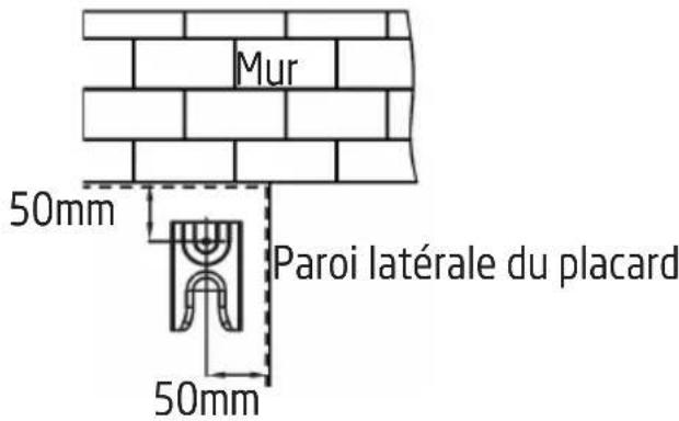
natural_image
Technical line drawing of a mechanical clamp or bracket assembly with two pins (no text or symbols)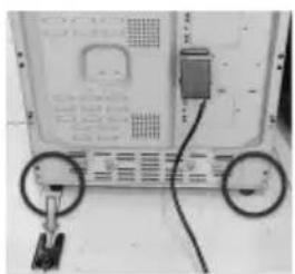
natural_image
Close-up of a computer monitor with two circular buttons and a cable, no visible text or symbols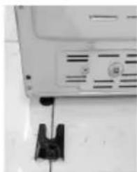
natural_image
Close-up of a white electronic device with ventilation slots and a black clip attached (no visible text or symbols)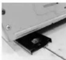
natural_image
Close-up of a computer drive with a black plastic component inserted into a slot (no visible text or symbols)natural_image
Close-up of a thin, curved wire with two arrows pointing to its ends (no text or symbols visible)natural_image
Three 3D-rendered kitchen utensils with crossed handles, shown in three circular frames (no text or symbols)DESCRIPTION DE LA SURFACE DE CUISSON
INSTRUCTIONS D'UTILISATION
natural_image
Simple circular diagram with a curved arrow indicating rotation or cycle (no text or symbols)
natural_image
Technical line drawing of a mechanical component or housing with internal structure and no visible text or symbolsRÉGLAGE DE L'HORLOGE
natural_image
Exterior view of a metal structural component with visible supports and a flat panel (no text or symbols)natural_image
Diagram of a vehicle being pulled by a pulley, showing motion direction (no text or symbols)Loquet
natural_image
Technical line drawing of a door frame and its internal component with a circular fan-like structure, both without any text or symbols.Hotline Darty France
natural_image
Abstract geometric shape with layered rectangular blocks (no text or symbols)
WAARSCHUWINGEN P. 30
BELANGRIJKE VEILIGHEIDSINSTRUCTIES....P. 33
BESCHRIJVING VAN DE ONDERDELEN ......P. 35
INSTALLATIE....P. 37
HET FORNUIS OP EEN JUISTE POSITIE PLAATSEN....P. 37
HET FORNUIS WATERPAS ZETTEN....P. 38
DE ANTI-KANTELKETTINGEN EN HAKEN INSTALLERENP.....P. 38
ELEKTRISCHE AANSLUITING....P. 40
BEDIENING P. 41
HET FORNUIS GEBRUIKEN....P. 41
DE OVEN GEBRUIKEN....P. 44
REINIGING EN ONDERHOUD....P. 50
natural_image
Pure geometric diagram of a rectangular grid with vertical lines, no text or symbols present1 rekken:
natural_image
Technical line drawing of a rectangular frame with internal hexagonal cutouts (no text or symbols)Ovenplaat:
natural_image
Close-up of a mechanical component with a spring attached to a textured surface (no visible text or symbols)natural_image
Pure technical line drawing of a mechanical assembly without any text, numbers, or symbolsMuur
natural_image
Interior view of a door with chain-link mechanism (no visible text or symbols)natural_image
Close-up of a hand using a power drill on tiled floor (no visible text or symbols)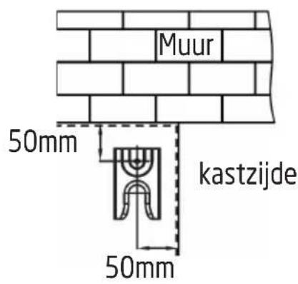
natural_image
Diagram of a mechanical clamp or bracket assembly with a screw and pin, no text or symbols present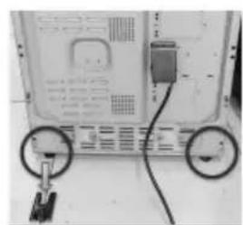
natural_image
Back view of a computer monitor with two circular buttons and cable (no visible text or symbols)
natural_image
Close-up of a laptop monitor with ventilation slots and a black clip attached (no visible text or symbols)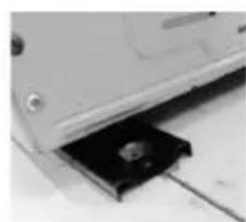
natural_image
Close-up of a computer drive with a black plastic component inserted into a slot (no visible text or symbols)WAARSCHUWING: DIT APPARAAT MOET GEAARD ZIJN.
natural_image
Close-up of a thin, curved wire with two black arrows pointing to its ends (no text or symbols present)natural_image
Three identical 3D-rendered kitchen utensils with a crossed handle, shown in three circular frames (no text or symbols)INDELING VAN HET KOOKOPPERVLAK
natural_image
Simple circular diagram with an arrow indicating clockwise rotation, enclosed in a frame (no text or symbols)
natural_image
Line drawing of a bed with a gable and patterned backrest, enclosed in a rounded rectangular frame (no text or symbols)DE KLOK INSTELLEN
natural_image
Close-up of a mechanical knob with a circular dial and an arrow pointing to the knob area (no text or symbols visible)UIT
DE OVENTIMER INSTELLEN
natural_image
Exterior view of a metallic structural component with visible grain and base plate (no text or symbols)natural_image
Technical line drawing of a door frame and a circular component with a rotating arrow (no text or symbols)⚠️ WARNINGS....P. 57
IMPORTANT SAFETY INSTRUCTIONS....P. 60
OVERVIEW....P. 62
INSTALLATION....P. 64
POSITIONING THE COOKER....P. 64
LEVELLING THE COOKER....P. 65
FITTING THE ANTI-TILT CHAINS AND HOOKS.....P. 65
ELECTRICAL CONNECTION....P. 67
OPERATION....P. 68
USING THE HOB....P. 68
USING THE OVEN....P. 71
CLEANING AND MAINTENANCE....P. 77
SPECIFICATIONS....P. 79
DISPOSAL....P. 82
WARNINGS
PLEASE READ THE FOLLOWING INSTRUCTIONS CAREFULLY BEFORE USING THE APPLIANCE AND KEEP FOR FUTURE REFERENCE.
- This appliance is intended for domestic household use only and should not be used for any other purpose or in any other application, such as for non-domestic use or in a commercial environment.
- This appliance can be used by children aged from 8 years and above and persons with reduced physical, sensory or mental capabilities or lack of experience and knowledge if they have been given supervision or instruction concerning use of the appliance in a safe way and understand the hazards involved. Children shall not play with the appliance. Cleaning and user maintenance shall not be made by children without supervision.
- If the supply cord is damaged, it must be replaced by the manufacturer, its service agent or similarly qualified persons in order to avoid a hazard.
- Place the tray and wire rack at the same level on both sides, make sure they are in a horizontal and stable position.
- The means for disconnection must be incorporated in the fixed wiring in accordance with the wiring rules.
- The appliance shall be installed in accordance with national wiring regulations NF C 15-100.
- Regarding the detailed instructions for the safe use of the appliance, the precautions during user maintenance and bulb replacement, refer to the sections "Operation" and "CLEANING and Maintenance".
- Regarding the method of fixing and cables connection, refer to the section "ELECTRICAL CONNECTION".
- WARNING: If the surface is cracked, switch off the appliance to avoid the possibility of electric shock.
- During use the appliance becomes hot. Care should be taken to avoid touching heating elements inside the oven.
- WARNING: The appliance and its accessible parts become hot
during use. Care should be taken to avoid touching heating elements. Children less than 8 years of age shall be kept away unless continuously supervised.
- Do not use harsh abrasive cleaners or sharp metal scrapers to clean the oven door glass since they can scratch the surface which may result in shattering of the glass.
- A steam cleaner is not to be used.
- Metallic objects such as knives, forks, spoons and lids should not be placed on the hob surface since they can get hot.
- Do not to stare at the hob elements.
- After use, switch off the hob element by its control and do not rely on the pan detector.
- WARNING: Ensure that the appliance is switched off before replacing the lamp to avoid the possibility of electric shock.
- The appliance is not intended to be operated by means of an external timer or separate remote-control system.
- WARNING: Unattended cooking on a hob with fat or oil can be dangerous and may result in fire. NEVER try to extinguish a fire with water, but switch off the appliance and then cover flame e.g. with a lid or a fire blanket.
- CAUTION: The cooking process has to be supervised. A short term cooking process has to be supervised continuously.
- WARNING: Danger of fire: do not store items on the cooking surface.
- The appliance must not be installed behind a decorative door in order to avoid overheating.
- WARNING: Accessible parts may become hot during use. Young children should be kept away.
- The temperature of accessible surfaces may be high when the appliance is operating.
- The door should preferably be closed in all cooking modes.
- Do not hang any cloth or garment to the handle of the oven.
- Do not line the oven's cavity with aluminum foil for easier cleaning: The oven may overheat and the enamel coating of the
cavity may be damaged.
- WARNING: In order to prevent tipping of the appliance, this stabilising means must be installed. Refer to the instructions for installation.
• Caution, possibility of tilting
• Anti-tip restraints
- The lamp inside the product is used for lighting of the product. This lamp is not suitable for household room illumination.
- Regarding the instructions for the method of the correct installation of the shelves, refer to the section "Using the oven".
- WARNING: Use only hob guards designed by the manufacturer of the cooking appliance or indicated by the manufacturer of the appliance in the instructions for use as suitable or hob guards incorporated in the appliance. The use of inappropriate guards can cause accidents.
- The centre of the internal bottom surface of a storage drawer can get hot.
• The appliance must not be placed on a base.
- Regarding the method of how to fix the appliance, refer to the section "FITTING THE ANTI-TILT CHAINS AND HOOKS".

IMPORTANT SAFETY INSTRUCTIONS
- The appliance should only be used for its intended purpose as described in the instruction manual. The manufacturer declines all responsibility for damage resulting from improper and irresponsible use.
- The appliance must be properly installed and grounded by a qualified technician. We will not be responsible for any damage that might be caused by failure to comply with these instructions.
- Do not wear loose or hanging garments when using the appliance. They could ignite if they touch a hot heating element and this may lead to the risk of burning yourself.
- Never touch the appliance when your hands or feet are wet.
- Do not operate the appliance barefooted.
- Do not store flammable materials on or near the appliance. This may cause a fire hazard.
- Maintenance and repair work must be made only by authorized service technicians.
- It is dangerous to alter or modify the specifications of the appliance in any way.
- Do not try to lift or move the appliance by pulling the door handle.
- While the oven door is open, do not let children climb on the door or sit on it.
- Always use oven gloves (not supplied) to remove and replace food in the appliance.
- Make sure the control knobs are always in off position when the appliance is not in use. Disconnect the appliance from the power supply before cleaning.
- Do not cover the openings and slots used for ventilation and heat dispersion.
- Stand back when opening the cooker door to allow any build up of steam or heat to disperse.
- Place pans centrally over the cooking zone making sure handles are kept away from the edge of the hob and cannot become heated by other pans.
• Take care to avoid heat/steam burns when operating the controls.
- Make sure the shelves are in the correct position before switching on the cooker.
- Keep the appliance clean as a build up of grease or fat from cooking can cause a fire.
- Do not leave the appliance unattended when in use.
- Never use the appliance as a room heater.

OVERVIEW
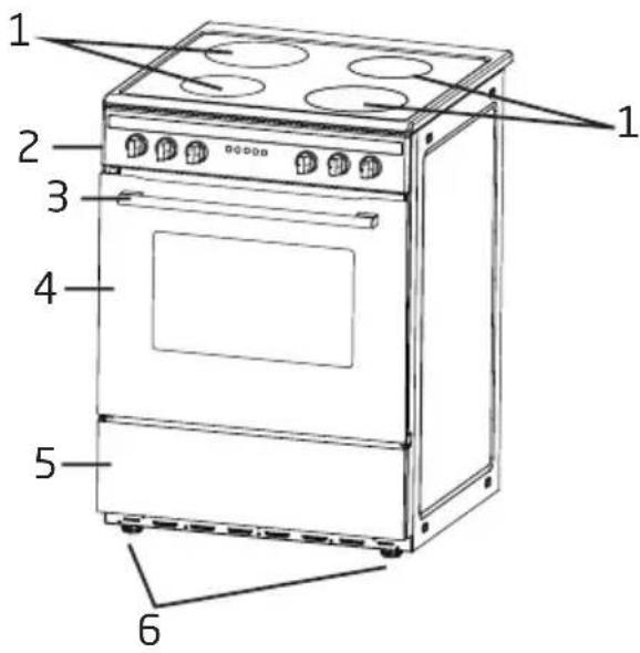
- Induction cooking zones
- Control panel
- Oven door handle
- Oven door
- Storage drawer
- Levelling feet
Oven accessories
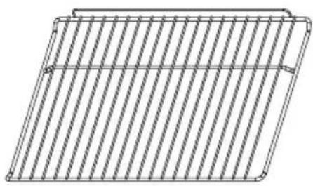
natural_image
Pure 3D wireframe diagram of a rectangular plate with diagonal striped pattern (no text or symbols)1 Rack :
for roasting and grilling food

natural_image
Technical line drawing of a rectangular tray or enclosure with internal grid lines (no text or symbols)Tray:
for cooking large quantities of food such as moist cakes, pastries, frozen food etc. or for collecting fat/spillage and meat juices
Control panel
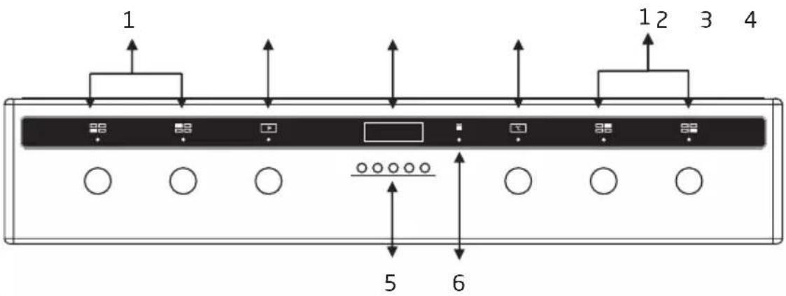
- Control knobs for induction cooking zones
- Function selector
- Display
- Temperature control knob
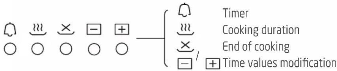
- Buttons
- Oven operating light

INSTALLATION
The following instructions should be read by a qualified technician to ensure that the appliance is installed, regulated and technically serviced correctly in compliance with current regulations.
Important: Disconnect the cooker from the electricity when making any adjustment, maintenance operation, etc.
The appliance can be installed next to furniture units which are no taller than the top of the cooker hob. For proper installation of the cooker, the following precautions must be taken:
- Hoods must be installed according to the requirements in the installation manual for the hoods themselves and in any case at a minimum distance of 650mm from the hob.
- Place the wall cabinets adjacent to the hood at a minimum height of 420mm from the hob.
- Should the cooker be installed beneath a wall cabinet, the latter should be situated at least 700mm away from the hob.
- Do not install the cooker near flammable materials (e.g. curtains).
- The cabinetry surrounding the cooker must be made of heat-resistant material and must be able to withstand temperatures of 50°C above room
temperature.
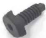
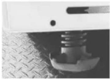
Your cooker is supplied with 4 feet for levelling the appliance. If necessary, these feet can be screwed into the housings in the corners of the cooker base.
natural_image
Close-up of a mechanical component with a threaded spring attached to a textured surface (no visible text or symbols)FITTING THE ANTI-TILT CHAINS AND HOOKS
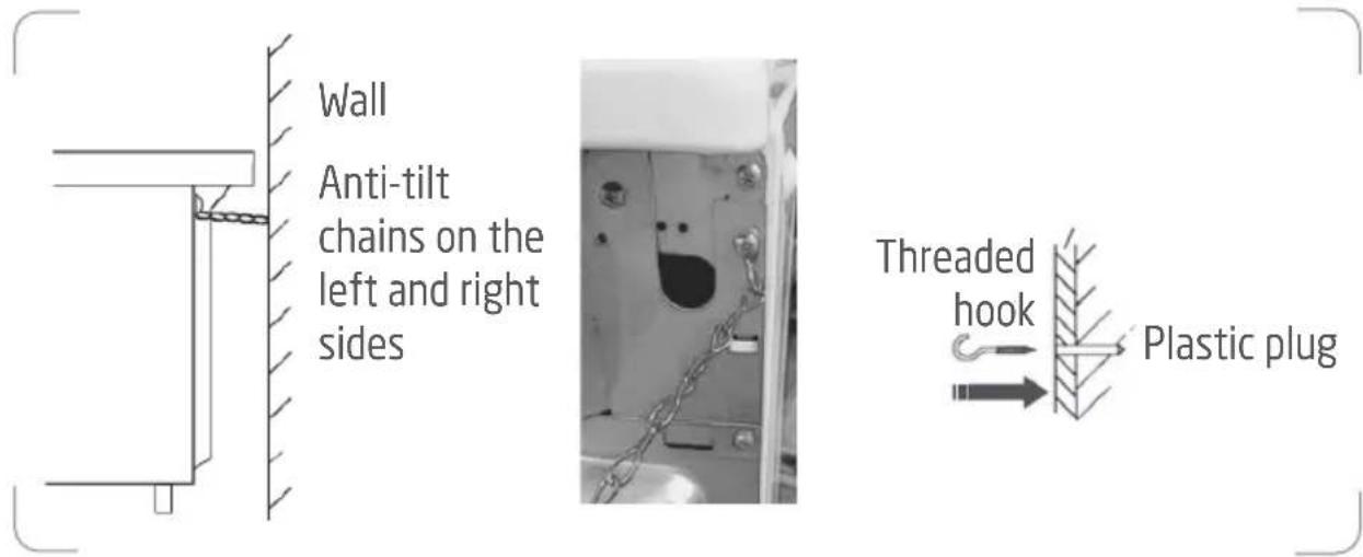
To prevent the cooker from tipping forwards in the event of children standing on the oven door or users putting extreme weight on the door when in open position, two supplied chains MUST BE fixed to the back of the cooker which should at all times be secured to the threaded hooks which are securely fixed to the wall.
-
After you have located where the cooker is to be positioned, mark on the wall the place where the two threaded hooks have to be fitted.
-
Drill two 8mm diameter holes in the wall and insert the supplied plastic plugs into the wall.
IMPORTANT! Before drilling the holes, check that you will not damage any pipes or electrical wires. - Secure the threaded hooks into the plastic plugs.
- Move the cooker to the wall and secure the chains to the back of the cooker.
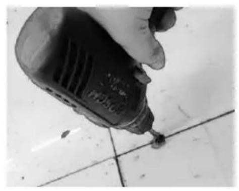
Fitting the Anti-tilt bracket on the Ground
- Drill a hole into the cabinet bottom.
- The distance between the hole and wall or cabinet side must be no less than 50mm.
natural_image
Close-up of a hand using a power drill on tiled floor (no visible text or symbols)
-
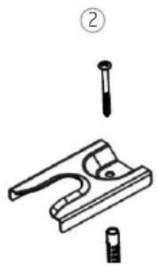
Hammer the expansion plug into the hole, then fix the anti-tilt bracket to the cabinet bottom by tightening the screw.
-
- Slide the cooker into place, ensuring that the left or right foot is securely slid into the anti-tilt bracket.
natural_image
Technical line drawing of a mechanical clamp or bracket assembly with two pins and a base (no text or symbols)
natural_image
Close-up of a computer monitor with two circular buttons and cable, no visible text or symbols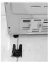
natural_image
Close-up of a white electronic device with a black clip attached to the side (no visible text or symbols)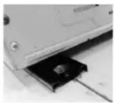
natural_image
Close-up of a computer drive with a black drive slot inserted into a slot (no visible text or symbols)ELECTRICAL CONNECTION
IMPORTANT! Electrical connections must only be performed by a qualified and authorised electrician.
WARNING: THIS APPLIANCE MUST BE EARTHED.
The brown wire must be connected to the terminal marked L.
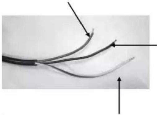
natural_image
Close-up of a black cable with two curved wires and directional arrows indicating fiber ends (no text or symbols)The blue wire must be connected to the terminal marked N.
The green and yellow wire must be connected to the terminal marked E or the earth symbol ⏻

OPERATION
When you operate the cooker for the first time, an odour may be emitted, this will cease after a period of use. This odour is due to temporary finish on oven liners and elements and also any moisture absorbed by the insulation.
Ensure that the room is well ventilated (e.g. open a window or use an extractor fan) and that persons who may be sensitive to the odour avoid any fumes.
USING THE HOB
PAN REQUIREMENT
Compatible materials: steel, enamelled steel, cast iron, ferromagnetic stainless-steel, aluminium with ferromagnetic bottom.
Non compatible materials: aluminium and stainless-steel without ferromagnetic bottom, copper, brass, glass, ceramic, porcelain.
Pan manufacturers specify if their products are compatible with induction appliances.
To check if pans are compatible:
- Put a little water in a pan placed on an induction cooking zone set at the maximum power level. This water must heat in a few seconds.
- A magnet sticks on the bottom of the pan.
Certain pans can make noise when they are placed on an induction cooking zone. This noise does not mean any failure on the appliance and does not influence the cooking operation.
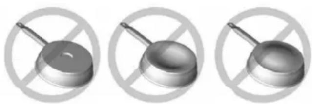
natural_image
Three identical metallic kitchen utensils with a crossed handle, shown against a white background with a crossed-out circle (no text or symbols)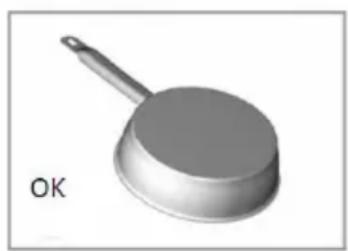
natural_image
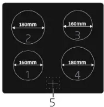
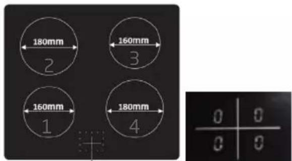
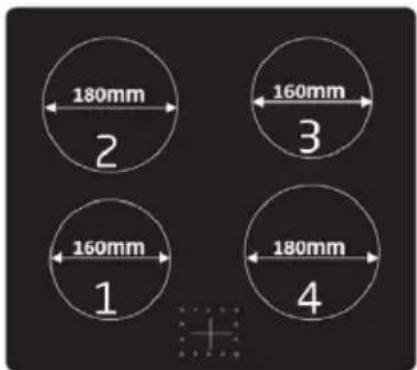
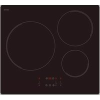
3D rendered image of a kitchen pan with a handle and lid, labeled 'OK' (no other text or symbols)COOKING SURFACE LAYOUT
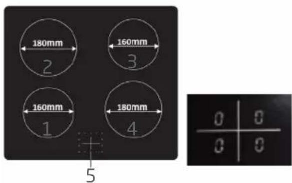
- Induction cooking zone 1500 W
- Induction cooking zone 2000 W
- Induction cooking zone 1500 W
- Induction cooking zone 2000 W
- Power level display from 0 to 9
The cooking zone, up to a limit, automatically adapts to the diameter of the pan. To obtain the best efficiency of your hob, please place the pan in the centre of the cooking zone.
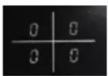
CONTROL KNOBS
Each knob controls a specific induction cooking zone. When you are not using the appliance, always ensure that all controls are in the OFF position and the display will show the number 0.
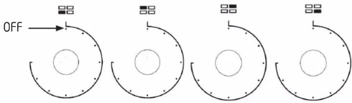
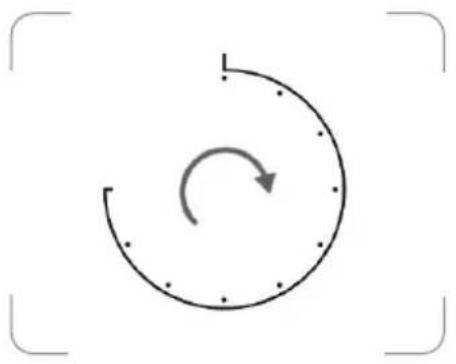
OPERATING INSTRUCTIONS
-
Turn the control knob to the desired power level for the selected hotplate.
-
The display will show the number from 1-9 to indicate the corresponding power level.
-
You can turn the control to 9 for fast cooking. To cook more slowly or simmer, turn the control to a lower setting according to the pan and the amount of liquid.
-
When you finish cooking, turn the control knob back to the OFF position. The display will show the number 0.
natural_image
Simple circular diagram with an arrow indicating clockwise rotation, enclosed in a frame (no text or symbols)
The cooking zone(s) will remain hot for some time. DO NOT touch until they have completely cooled down.
DETECTION OF SMALL NON-MAGNETIC ITEMS
When a unsuitable size or non-magnetic pan (e.g. aluminium), or some other small item (e.g. knife, fork, key) has been left on the cooking zone, the symbol will flash and the cooking zone will automatically enter the standby state after about 1 minute.
AUTO SHUT DOWN
The feature occurs whenever you forget to switch off a cooking zone. The default shutdown times are shown in the table below:
| Power level The cooking zones will shut down automatically after | |
| 1~3 | 8 hours |
| 4~6 | 4 hours |
| 7~9 | 2 hours |
ERROR CODES
These error codes are for guidance only and all faults should be diagnosed and repaired by a qualified technician.
| Display Possible causes Possible solution | ||
| F3 - F8 | Temperature sensor failure | Contact the store where you have purchased the appliance. |
| F9 - FE | Temperature sensor of the IGBT failure | Contact the store where you have purchased the appliance. |
| €1 / €2 | Abnormal supply voltage | Inspect whether power supply is normal and then turn the hob on. |
| €3 / €4 | Abnormal temperature Inspect the cookware. | |
| €5 / €6 | Bad induction hob heat radiation. | Restart after the induction hob cools down. |
USING THE OVEN
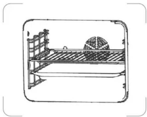
Before operating the oven, use a slightly damp cloth to carefully wipe the inner cavity wall. Clean the racks and tray and in warm soapy water before using. Rinse thoroughly.
Slide the rack/tray between the guide bars of the shelf support rails in the oven, and push it to the end.
In case the rack and tray are inserted together, lay the rack over the tray.
natural_image
Line drawing of a bed with a gumball and wall-mounted frame (no text or symbols)SETTING THE CLOCK
To enable use of the oven you must first set the clock in 24 hour format. If the clock is not set, the oven will not operate.
-
After plugging in the appliance, 000 and the letter 'A' will flash on the display.
-
Press and at the same time.
- The dot • between the hour and minute digits will flash.
- Repeatedly press ☐to set the correct time.
- You can also press and hold / for fast setting.
- Press and at the same time to confirm.
- The display will show the manual operation symbol .
• After about 3 seconds the dot will stop flashing, it indicates the time setting is confirmed.
COOKING
- Turn the function selector to select the desired function.
| Oven function Application | ||
 | Oven lamp To illuminate the oven interior | |
 | Defrost To thaw frozen food | |
 | Dual grill with fan | This function is suitable for cooking large quantities of food. |
 | Dual grill | |
 | This function ensures energy savings during cooking. | |
 | Radiant grill | This function is suitable for cooking small quantities of food. |
 | Convention with fan | This function is suitable for cooking large pieces of meat. |
 | Conventional | This function is suitable for single traditional cooking. |
 | Bottom heat | This function is suitable for casseroles, curries and any slow cooking. |
-
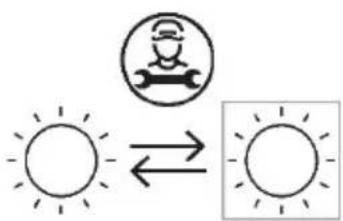
Turn the temperature control knob to select the desired temperature.
-
The oven operating light will illuminate.
-
Before placing food in the oven you may need to preheat the oven for 10 minutes.
-
When the selected temperature is reached, the operating light will go out.
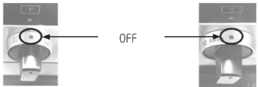
- To switch off the oven, turn the function selector and temperature control knob to the OFF position.
SETTING THE OVEN PROGRAMMER/TIMER
Setting the Cooking Duration
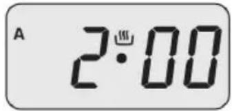
Select the cooking duration to switch the oven on for a specific period of time. At the end of this time the oven will automatically switch off. The maximum programmable cooking duration is 9 hours.
For example, if a dish needs 2 hours to cook, you can set the oven to turn off 2 hours later. This allows you to be sure that your food will be cooked for a set length of time.
- Turn the function selector to select the required cooking function.
- Turn the temperature control knob to set the required temperature.
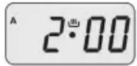
- Press .
• The display will show .000 - Repeatedly press or press & hold √-4. until the display shows 2•00.
• The display will show the letter 'A'.
- After about 3 seconds the display will return to the clock time, indicating the setting is confirmed.
• After the setting is confirmed, you can press to check the remaining
cooking time
- When the set time has elapsed, the buzzer will sound and the oven will automatically switch off.
• The letter 'A' will flash.
- The buzzer can be silenced by pressing , or .
To cancel the setting, press and at the same time. The letter 'A' will disappear from the display.
Setting the Start and End of Cooking Time
This function incorporates both cooking duration and end time selection; it is meant to be used when you wish to delay the start time of your cooking. The timer will calculate the appropriate start time based on the selected cooking duration and end time.
- Turn the function selector to select the required cooking mode.
- Turn the temperature control knob to set the required temperature.
- Press .The display will show .000
-
Repeatedly press or press & hold ☐ to set the required length of cooking time.
• The display will show the letter 'A'. -
Press . ✗ • The display will show the sum of the current time plus the set cooking time.
-
Repeatedly press or press & hold ☐ to set the end of cooking time.
-
After about 3 seconds the display will return to the clock time, indicating the setting is confirmed.
- After the setting is confirmed, you can press 📄 to check the remaining cooking time and press ✗ to check the cooking end time.
- The oven will switch on automatically at the end of cooking time minus the cooking duration.
End of Cooking time Cooking Duration
18:34
Start of Cooking Time
- When the set end of cooking time is reached, the oven will switch off and the buzzer will sound.
• The letter 'A' will flash.
• The buzzer can be silenced by pressing, for ∞
To cancel the setting, press and at the same time. The letter 'A' will disappear from the display.
Setting the Timer
The countdown timer can be set up to 23 hours and 59 minutes.
- Press
• The display will show and the symbol will flash.
- Repeatedly press or press & hold √ until the desired time is displayed.
- After about 3 seconds the display will return to the clock time, indicating the setting is confirmed.
• The symbol will stop flashing.
• After the setting is confirmed, you can press 📄 to check the remaining time.
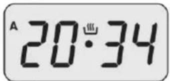
20:34
- When the set time is reached, the buzzer will sound and the symbol will flash.
• The buzzer can be silenced by pressing, or ✗
To cancel the setting, press 📄 and then repeatedly press 📄 until the display shows 📄 when the display return to the clock time, press or ✗ and the symbol will disappear from the display.
Setting the Buzzer
The buzzer can be set to 3 different levels. When the buzzer is sounding, repeatedly press to change the setting.
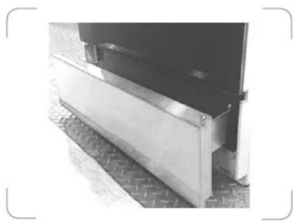
Storage drawer below the oven
Below the oven a storage drawer can be used to obtain cooking pans and cooker accessories.
natural_image
Exterior view of a metal structural component with visible supports and a flat panel (no text or symbols)Caution: Do not store inflammable materials inside this drawer.

CLEANING AND MAINTENANCE
Switch off and disconnect the appliance from the power supply and allow it to cool completely before cleaning.
Clean the outside of the appliance with a slightly damp cloth. Dry it thoroughly. Never use abrasive or chemical cleaning agents.
Remove rack and tray. Wash them in warm soapy water. Rinse and dry them thoroughly before use.
After each use, wipe the inside of the oven using a household detergent. Wipe clean with a slightly damp cloth and dry thoroughly.
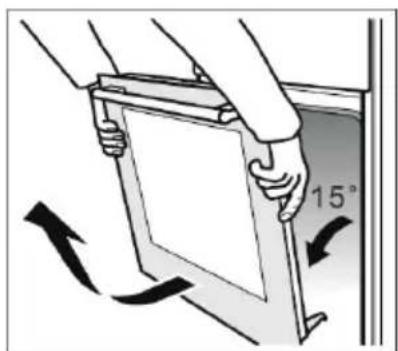
Removing the oven door for easy cleaning
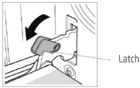
- Open the door completely.
- There are swivel latches on the left and right door hinges. Lift the latches as shown.
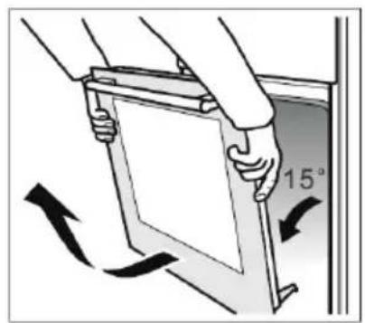
- Close the door gently until it meets the open latches.
- Support the door by holding both sides. Continue to close the door further then lift to disengage the hinge from the bottom.
- Pull the door outwards you to remove the hinges from their slots.
- To replace the door, repeat the above steps in reverse order, making sure the hinge slots engages over the edge of the door frame.
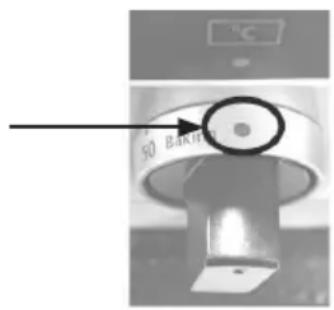
Replacing the oven light bulb
WARNING: Ensure that the appliance is switched off before replacing the lamp to avoid the possibility of electric shock.
The bulb is located inside the oven on the back wall.
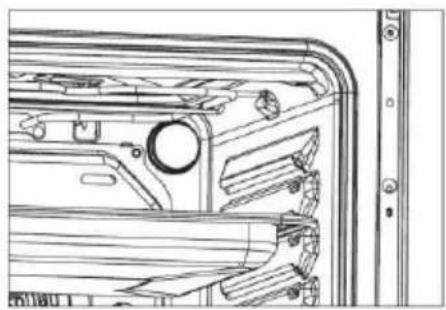
natural_image
Technical line drawing of a mechanical component with no visible text or symbols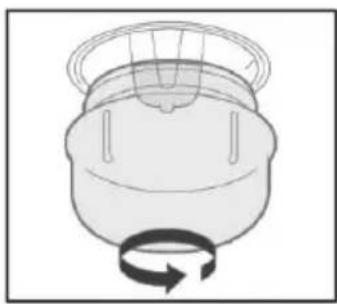
natural_image
Simple line drawing of a mechanical component with a rotating arrow (no text or symbols)- Rotate the lamp cover to remove.
- Unscrew and replace the bulb with a new one suitable for high temperatures (300°C) with the following specifications: 230V, G9 25W.
- Twist the lamp cover back on.
Replaceable light source by a professional
This product contains a light source of energy efficiency class G.
Below is the sheet of domestic hob according to EU regulation No. 66/2014.
| Informationfordomesticelectrichobs | |||
| Symbol | Value | Unit | |
| Modelidentification | P601IMCIXT,P601IMCWHT,P601IMCIBK | ||
| Typeofhob | Electrichob | ||
| Numberofcookingzonesand/orareas | 4 | ||
| Heatingtechnology(inductioncooking zonesandcookingareas, radiantcooking zones,solidplates) | Inductioncookingzonesandcookingareas | ||
| Forcircularcookingzonesorarea:diameterofusefulsurfaceareaper electricheatedcookingzone,roundedto thenearest5mm | ∅ | Zone1:16,0Zone2:18,0Zone3:16,0Zone4:18,0 | cm |
| Energyconsumptionpercookingzoneor areacalculatedperkg | EC_electriccooking | Zone1:198,4Zone2:191,6Zone3:178,3Zone4:168,0 | Wh/kg |
| Energyconsumptionforthehob calculatedperkg | EC_electrichob | 184,1Wh/kg | |
Energy efficiency performance limits for domestic hobs
| Timetable (entry into force 20 Feb., 2014) | Electric hob (EC electric hob in Wh/kg) | 184.1Wh/kg, it is valid until 19 Feb., 2019 |
| From 1 year after the entry into force (from 20 Feb., 2015) | EC electric hob<210 | |
| From 3 years after the entry into force (from 20 Feb., 2017) | EC electric hob <200 | |
| From 5 years after the entry into force (from 20 Feb., 2019) | EC electric hob <195 |
Below is the sheet of domestic oven according to EU regulation No. 66/2014.
| Informationfordomesticovens | |||
| Symbol | Value | Unit | |
| Modelidentification | P601IMCIXT,P601IMCWHT,P601IMCIBK | ||
| Typeofoven | Electricoven | ||
| Massoftheappliance | M | 52,5 | kg |
| Numberofcavities | 1 | ||
| Heatsourcepercavity(electricityorgas) | Electricity | ||
| Volumepercavity | V | 70 | I |
| Energyconsumption(electricity)requiredtoheatastandardisedloadinacavityofanelectricheatedovenduringacycleinconventionalmodepercavity(electricfinalenergy) | EC_electriccavity | 0,72kWh/cycle | |
| Energyconsumptionrequiredtoheatastandardisedloadinacavityofanelectricheatedovenduringacycleinfan-forcedmodepercavity(electricfinalenergy) | EC_electriccavity | 0,78kWh/cycle | |
| EnergyEfficiencyIndexpercavity | EEI_cavity | 85,7 | |
| Ecodesign requirements according to EU regulation No. 66/2014 | ||||
| Item | Measured Value | Stage 1 Stage 2 Stage 3 | ||
| EEIcavity 85.7 | ☒ 1 year after enter into force <146 | ☒ 2 years after entry into force <121 | ☒ 5 years after entry into force <96 | |
Freestanding cooker specifications
| Rating / Supply Voltage and frequency | 220V-240V~ 50Hz |
| Oven power | 3000 W |
| Hob power | 7000 W:Left rear and right front: 2000WLeft front and right rear: 1500W |
| Oven lamp power | 25 W |
| Top heating element (W) | 950W |
| Grill heating element (W) | 2000 W |
| Bottom heating element (W) | 1100 W |
| Rotary motor (W) | 33 W |
| Cleaning (Enamel/catalytic/Pyrolytic) | Enamel |
| Net Weight kg | 52.5kg |
| Outside dimensions (W*D*H) | 600* 650* 850mm |
| Energy Class (letter for the sticker) * | A |
| Usable volume (litres) | 70 L |
| Size : (Small/Medium/Large) | Large |
| Made in | RPC |
* Energy class: A+++.....D (A+++=economical D=less economical)

DISPOSAL
As a responsible retailer we care about the environment. As such we urge you to follow the correct disposal procedure for the appliance and packaging materials. This will help conserve natural resources and ensure that it is recycled in a manner that protects health and the environment.
You must dispose of this appliance and its packaging according to local laws and regulations.
Because this appliance contains electronic components, the appliance and its accessories must be disposed of separately from household waste when the appliance reaches its end of life.
Contact your local authority to learn about disposal and recycling.
The appliance should be taken to your local collection point for recycling. Some collection points accept appliance free of charge.
We apologise for any inconvenience caused by minor inconsistencies in these instructions, which may occur as a result of product improvement and development.
EU Declaration of Conformity
Product Description:
natural_image
Front view of a stainless steel oven with control knobs and ventilation grilles (no visible text or symbols)The object of the declaration described above is in conformity with the relevant Union
harmonisation legislation:
Low Voltage Directive (LVD)
Eco design requirements for energy-related products (ErP)
RoHS
EMC:
EN 55014-1:2017 + A11:2020
EN 55014-2:2015
EN IEC 61000-3-2:2019
EN 61000-3-3:2013 + A1:2019
LVD :
EN 60335-1:2012 + A11:2014 + A13:2017 + A1:2019 + A14:2019 + A2:2019
EN 60335-2-6:2015 + A1:2020 + A11:2020
EN 62233:2008
ErP :
(EU) 65/2014
(EU) 66/2014
(EC) No 1275/2008
(EU) No 801/2013
(EU) 2017/254
(EU) No 2016/2282
EN 60350-1:2016
EN 50564:2011
This declaration of conformity is drawn up under the sole responsibility of the manufacturer.
The person responsible for this declaration is:
Place, Date / Lieu :
Ivry-sur-Seine, mars 16, 2022


PROLINE

- AVERTISSEMENTS
- MERCI DE BIEN VOULOIR LIRE LES CONSIGNES DE SÉCURITÉ ATTENTIVEMENT AVANT L'UTILISATION DE L'APPAREIL ET DE LES CONSERVER POUR CONSULTATION ULTERIEURE.
- DESCRIPTION DE LA SURFACE DE CUISSON
- INSTRUCTIONS D'UTILISATION
- RÉGLAGE DE L'HORLOGE
- Hotline Darty France
- INDELING VAN HET KOOKOPPERVLAK
- DE KLOK INSTELLEN
- DE OVENTIMER INSTELLEN
- WARNINGS
- PLEASE READ THE FOLLOWING INSTRUCTIONS CAREFULLY BEFORE USING THE APPLIANCE AND KEEP FOR FUTURE REFERENCE.
- IMPORTANT SAFETY INSTRUCTIONS
- OVERVIEW
- INSTALLATION
- FITTING THE ANTI-TILT CHAINS AND HOOKS
- Fitting the Anti-tilt bracket on the Ground
- ELECTRICAL CONNECTION
- OPERATION
- USING THE HOB
- PAN REQUIREMENT
- CONTROL KNOBS
- OPERATING INSTRUCTIONS
- DETECTION OF SMALL NON-MAGNETIC ITEMS
- AUTO SHUT DOWN
- ERROR CODES
- USING THE OVEN
- SETTING THE CLOCK
- COOKING
- SETTING THE OVEN PROGRAMMER/TIMER
- Setting the Cooking Duration
- Setting the Start and End of Cooking Time
- Setting the Timer
- Setting the Buzzer
- Storage drawer below the oven
- CLEANING AND MAINTENANCE
- Removing the oven door for easy cleaning
- Replacing the oven light bulb
- DISPOSAL
- EMC:
- LVD :
- ErP :
- PROLINE
Brand : PROLINE
Model : P601IMCIXT
Category : Cooker